JP2012126546A - Medium transport apparatus - Google Patents
Medium transport apparatusDownload PDFInfo
- Publication number
- JP2012126546A JP2012126546AJP2010281427AJP2010281427AJP2012126546AJP 2012126546 AJP2012126546 AJP 2012126546AJP 2010281427 AJP2010281427 AJP 2010281427AJP 2010281427 AJP2010281427 AJP 2010281427AJP 2012126546 AJP2012126546 AJP 2012126546A
- Authority
- JP
- Japan
- Prior art keywords
- layer control
- cpu
- lower layer
- medium
- paper
- Prior art date
- Legal status (The legal status is an assumption and is not a legal conclusion. Google has not performed a legal analysis and makes no representation as to the accuracy of the status listed.)
- Pending
Links
Images


Landscapes
- Controlling Sheets Or Webs (AREA)
- Control Of Position Or Direction (AREA)
Abstract
Translated fromJapaneseDescription
Translated fromJapanese本発明は、分散協調システムにおける制御ネットワーク構成を備えた媒体搬送装置に関する。 The present invention relates to a medium transport apparatus having a control network configuration in a distributed cooperative system.
電子写真方式を採用する画像形成装置のプリンタデバイス制御では、一つのCPUによる集中制御が行われている。しかし、集中制御によるCPU負荷の増大によって、より高性能なCPUが必要となる。さらに、プリンタデバイスの制御負荷の増大に伴い制御通信束線を制御CPU基板から離れた制御負荷ドライバユニットまで引き回す必要があり、長大な制御通信束線が多数必要となっていた。このような問題を解決するために、電子写真システムを構成する各制御モジュールを個々のサブCPUに分割する制御形態が注目されている。 In printer device control of an image forming apparatus that employs an electrophotographic system, centralized control is performed by a single CPU. However, an increase in CPU load due to centralized control requires a higher performance CPU. Further, as the control load of the printer device increases, it is necessary to route the control communication bundle to the control load driver unit that is away from the control CPU board, and many long control communication bundles are required. In order to solve such a problem, a control form in which each control module constituting the electrophotographic system is divided into individual sub CPUs has attracted attention.
このように複数のCPUにより個々の部分モジュール制御機能を分割し制御システム構築する例については、複写機以外のいくつかの制御機器製品分野で提案されている。例えば、特許文献1は、ロボットアームにおける適応事例であり、複数のアーム関節アクチュエータを制御する複数のサブ制御CPUと、それらの協調制御を統括するためのメイン制御CPUとで、制御システムを構築する方法に関する。この方法では、メイン制御CPUと各サブ制御CPUは、制御データを通信するネットワークと、メイン制御CPUと各サブ制御CPUとで共通するクロック供給部とを有する。
そして、メイン制御CPUはサブ制御CPUに予めネットワークを通じて協調制御のための制御データを与え、クロック供給部からの共通のクロック信号に同期して各サブ制御CPUは先にネットワークを通じて得た制御データに基づいてアクチュエータを駆動する。Examples of constructing a control system by dividing individual partial module control functions by a plurality of CPUs have been proposed in several control device product fields other than copying machines. For example,
Then, the main control CPU gives control data for cooperative control to the sub-control CPU in advance through the network, and each sub-control CPU uses the control data previously obtained through the network in synchronization with the common clock signal from the clock supply unit. Based on this, the actuator is driven.
しかしながら、上記従来技術には以下に記載する問題がある。例えば、ロボットアームなどにおいては、高速な応答性が必要となる協調制御を実現することを前提に、各モジュールが高速ネットワークで接続されている。協調制御とは、例えば、アームで掴む対象物との距離を検知する距測検知制御モジュールとアクチュエータ制御モジュールとを連動させて実現するフィードバック制御などである。
協調制御において、まず、次の3ステップにおいてネットワークを使用する。
(1)距測検知制御モジュールからメイン制御CPUに検知量を通知するステップ。
(2)メイン制御CPUから各アクチュエータ制御モジュールのサブ制御CPUに制御データを与えるステップ。
(3)同期クロックを通知するステップ。
フィードバック制御の高速な応答性を得るためにネットワークのオーバーヘッドが無視できないため、高速なネットワークが必要となる。However, the above prior art has the following problems. For example, in a robot arm or the like, modules are connected via a high-speed network on the assumption that cooperative control that requires high-speed response is realized. The cooperative control is, for example, feedback control realized by linking a distance detection control module that detects a distance from an object held by an arm and an actuator control module.
In the cooperative control, first, the network is used in the following three steps.
(1) A step of notifying the main control CPU of the detection amount from the distance detection control module.
(2) A step of giving control data from the main control CPU to the sub-control CPU of each actuator control module.
(3) A step of notifying the synchronous clock.
Since the overhead of the network cannot be ignored in order to obtain high-speed response of feedback control, a high-speed network is required.
このようなシステム構成をそのまま画像形成装置の分散制御に適用した場合、各モジュールを高速なネットワークで接続することになるが、高速なネットワーク通信部はそれ自体が高価であることからコストが増大してしまう。
画像形成装置での媒体搬送の分散制御では、複数のサブCPU間で媒体の受渡しを行うため、タイミング同期がとれないと引っ張り合いやループによりジャムになってしまう。
ただし、媒体受渡しを行う隣接したサブCPU間でのみタイミング同期が取れれば良く、またタイミング信号さえ授受できれば良いことから、多量の制御データの授受は必要とされない。
しかしながらタイミング同期のためだけに高速なネットワーク通信を導入することは明らかにコスト高につながり、分割制御を適用することが困難であった。When such a system configuration is applied as it is to distributed control of an image forming apparatus, each module is connected via a high-speed network. However, the high-speed network communication unit itself is expensive, which increases the cost. End up.
In the distribution control of the medium conveyance in the image forming apparatus, since the medium is transferred between the plurality of sub CPUs, jamming may occur due to pulling or looping if timing synchronization is not achieved.
However, since it is only necessary to synchronize timing between adjacent sub-CPUs that perform medium delivery, and only timing signals can be exchanged, it is not necessary to exchange a large amount of control data.
However, introducing high-speed network communication only for timing synchronization clearly leads to high costs, and it is difficult to apply division control.
本発明は、上述の問題に鑑みて成されたものであり、コストの増大を招くことなく、複数の制御部による分割制御を実現する画像形成装置を提供することを目的とする。 SUMMARY An advantage of some aspects of the invention is that it provides an image forming apparatus that realizes division control by a plurality of control units without causing an increase in cost.
本発明は、例えば、複数のスレーブCPUを用いて分散制御を行う媒体搬送装置として実現できる。媒体搬送装置は、複数の搬送パスをそれぞれ管轄して、協働して媒体搬送を行う複数のスレーブCPUと、前記複数のスレーブCPUを統括的に制御するサブマスタCPUと、前記複数のスレーブCPUに接続された媒体検知手段とを有し、前記複数のスレーブCPUは、前記媒体検知手段からの信号に基づいて同期駆動を行う。 The present invention can be realized, for example, as a medium transport device that performs distributed control using a plurality of slave CPUs. The medium transport apparatus has a plurality of slave CPUs that control each of the plurality of transport paths and cooperate to transport the medium, a sub-master CPU that centrally controls the plurality of slave CPUs, and the plurality of slave CPUs. The plurality of slave CPUs perform synchronous driving based on signals from the medium detection means.
本発明によれば、例えば、コストの増大を招くことなく、複数の制御部による分割制御を実現する媒体搬送装置を提供できる。 According to the present invention, for example, it is possible to provide a medium transport apparatus that realizes division control by a plurality of control units without causing an increase in cost.
<画像形成装置の構成>
図1を用いて、画像形成部1の詳細について説明する。図1は、本実施形態に係る画像形成部1の構成例を示す断面図である。なお、本実施形態の画像形成部1は電子写真方式を採用している。<Configuration of image forming apparatus>
Details of the
フルカラー静電画像を形成するための像担持体としての感光体ドラム(以下、単に「感光体」と称する。)225の周囲には、一次帯電装置221、露光装置218、現像装置223、転写装置220、除電器222、クリーナ装置271が配置されている。なお、図1において、符号に付されたY,M,C,Kはイエロー、マゼンタ、シアン、ブラックを表している。
転写ベルト226は、ローラ227、228、229に張架されている。ローラ229は、2次転写装置231としての転写ローラのバックアップローラとして機能する。Around a photosensitive drum (hereinafter simply referred to as “photosensitive member”) 225 as an image carrier for forming a full-color electrostatic image, there are a primary charging device 221, an exposure device 218, a developing device 223, and a transfer device. 220, a static eliminator 222, and a cleaner device 271 are arranged. In FIG. 1, Y, M, C, and K added to the reference numerals represent yellow, magenta, cyan, and black.
The
カセット240、241及び手差し給紙部253は、レジストローラ255、給紙ローラ対235及び縦パスローラ対236、237、記録材の有無を検知するためのシートなし検知センサ243、244、245を備える。また、カセット240、241及び手差し給紙部253は、それぞれ記録材のピックアップ不良を検知するための給紙センサ247、248、249を備える。 The
ここで、画像形成部1による画像形成動作について説明する。画像形成が開始されると、カセット240、241及び手差し給紙部253に格納された記録材は、ピックアップローラ238、239、254により1枚毎に給紙パス266上に搬送される。給紙パス266に給送された記録材は、給紙ローラ対235、236、237によりレジストローラ255へと搬送されると、その直前のレジストセンサ256により記録材の通過が検知される。 Here, an image forming operation by the
レジストセンサ256により記録材の通過が検知された時点で、本実施形態では所定の時間が経過した後に一端搬送動作を中断する。その結果、記録材は停止しているレジストローラ255に突き当たり搬送が停止される。その際、記録材の進行方向端部が搬送経路に対して垂直になるように搬送位置が固定され、記録材の搬送方向が搬送経路に対してずれた状態の斜行が補正される。以下では、この処理を位置補正と称する。位置補正は、以降の記録材に対する画像形成方向の傾きを最小化するために必要となる。位置補正後、レジストローラ255を起動させることにより、記録材は、2次転写装置231へ供給される。なお、レジストローラ255は、駆動源に結合され、回転駆動を行う。 In this embodiment, when the
トナー像は、2次転写装置231で、給紙部より搬送された記録材に転写された後、レジスト後搬送パス268を通過し、定着搬送ベルト230を介して、定着装置234へと搬送される。
その後、記録材は、排紙フラッパ257により排紙パス258側に搬送パスが切り替えられることにより、排紙ローラ270によってそのまま排紙トレー242に排紙される。The toner image is transferred to the recording material conveyed from the paper feeding unit by the
Thereafter, the recording material is discharged to the
画像形成部1は、図1に示す各制御負荷を、搬送モジュールA280、搬送モジュールB281、作像モジュール282、定着モジュール283という4つの制御ブロックに分けている。搬送モジュールA280(サブマスタCPU601)、搬送モジュールB281(サブマスタCPU901)、作像モジュール282(サブマスタCPU701)、定着モジュール283(サブマスタCPU801)のそれぞれは、自律的に制御を行っている。媒体搬送装置1000において、複数の駆動ユニット(スレーブCPU)と統括手段(サブマスタCPU)とは、協働して媒体搬送を行う。さらに、画像形成部1は、これらの4つの制御ブロックを統括して画像形成装置として機能させるためのマスタモジュール284(マスタCPU1001)を有する。 The
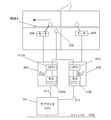
次に、図2を用いて、本実施形態における媒体搬送装置1000の具体的なマスタCPU、サブマスタCPU、スレーブCPUの基板構成上の配置について説明する。図2は、本実施形態に係る画像形成部1の制御基板の一例を示す図である。 Next, a specific arrangement of the master CPU, sub-master CPU, and slave CPU of the
本実施形態によれば、図2に示すように、様々な制御基板の構成を採用することができる。例えば、サブマスタCPU(上層制御手段)601とスレーブCPU(下層制御手段)602、603、604、605とは、同一の基板上に実装されている。また、サブマスタCPU701及びスレーブCPU702、703、704、または、サブマスタCPU801及びスレーブCPU802、803のように、サブマスタCPUと個々のスレーブCPUを独立の基板として実装してもよい。また、スレーブCPU705、706のように、一部のスレーブCPUを同一の基板上に実装してもよい。また、サブマスタCPU901及びスレーブCPU902のように、サブマスタCPUとスレーブCPUの一部だけを同一基板上に配置してもよい。このように、サブマスタCPU若しくはスレーブCPUを同一基板上に実装することにより、複数基板間の結線を削減することができる。 According to the present embodiment, various control board configurations can be employed as shown in FIG. For example, the sub master CPU (upper layer control means) 601 and the slave CPUs (lower layer control means) 602, 603, 604, 605 are mounted on the same substrate. Further, the sub master CPU and individual slave CPUs may be mounted as independent boards, such as the
<制御フロー>
次に、図3を用いて、本実施形態に係る画像形成部1の制御フローについて説明する。図3は、本実施形態に係る画像形成部1の制御フローを示すシーケンス図である。なお、図3に示すシーケンス図は、1枚の記録材に対して画像形成を行う場合の処理に関する。<Control flow>
Next, a control flow of the
まずステップS1201において、マスタCPU1001は、画像形成を開始する前に各サブマスタCPU601、701、801、901に対して画像形成前処理の開始を指示する。その後、ステップS1202、S1203、S1204、S1205において、各サブマスタCPU601、701、801、901は、画像形成を行うための前処理を実行する。具体的には、サブマスタCPU601は、給紙前処理を実行する(S1202)。サブマスタCPU701は、作像前処理を実行する(S1203)。サブマスタCPU801は、定着前処理を実行する(S1204)。サブマスタCPU901は、搬送前処理を実行する(S1205)。 First, in step S1201, the
次に、ステップS1206aにおいて、マスタCPU1001は、操作部や、外部I/Fからの操作者の指示に応じて1枚目の記録材の給紙開始をサブマスタCPU601に指示する。 Next, in step S1206a, the
給紙開始の指示を受けると、ステップS1207aにおいて、サブマスタCPU601は、給紙処理を開始する。給紙処理においては、カセット240、241、手差し給紙部253のいずれかに載置された記録材をレジストローラ255の位置まで搬送し一時停止させる。その後、ステップS1208aにおいて、サブマスタCPU601は、一定時間経過後、レジストローラ255を再起動させて記録材を2次転写装置231の位置まで搬送するとともに、サブマスタCPU701に対して作像開始を指示する。 When receiving a paper feed start instruction, in step S1207a, the
作像開始の指示を受けると、ステップS1209aにおいて、サブマスタCPU701は、記録材への作像処理及び転写処理を実行する。その後、ステップS1210aにおいて、一定時間が経過し、画像形成された記録材が定着装置234に向かうことが確定すると、サブマスタCPU701はサブマスタCPU801に定着開始を指示する。 Upon receiving an instruction to start image formation, in step S1209a, the
定着開始の指示を受けると、ステップS1211aにおいて、サブマスタCPU801は、記録材の熱定着処理を実行する。その後、ステップS1212aにおいて、一定時間が経過し、定着された記録材が排紙ローラ270に向かうことが確定すると、サブマスタCPU801はサブマスタCPU901に排紙開始を指示する。 Upon receiving an instruction to start fixing, in step S1211a, the
排紙開始の指示を受けると、ステップS1213aにおいて、サブマスタCPU901は、記録材の排紙処理を実行する。その後、ステップS1214aにおいて、サブマスタCPU901は、排紙を完了すると、マスタCPU1001にその旨を通知する。 When receiving a discharge start instruction, in step S1213a, the
排紙完了の通知を受けると、ステップS1215において、マスタCPU1001は、各サブマスタCPU601、701、801、901に対して画像形成後処理の開始を指示する。その後、ステップS1216、S1217、S1218、S1219において、各サブマスタCPU601、701、801、901は、画像形成を終了するための後処理を実行する。具体的には、サブマスタCPU601は、給紙後処理を実行する(S1216)。サブマスタCPU701は、作像後処理を実行する(S1217)。サブマスタCPU801は、定着後処理を実行する(S1218)。サブマスタCPU901は、搬送後処理を実行する(S1219)。 When the notification of the completion of paper discharge is received, in step S1215, the
上述したシーケンスにおいては、1枚の記録材に対する給紙から排紙までの一連の画像形成処理について説明した。一方、複数枚の記録材に対して、連続して画像形成を実行する場合には、例えば、図3のステップS1206b〜1214bに示すように、1枚目の記録材の画像形成開始から所定時間が経過した後に連続して画像形成を実行することができる。この場合、記録材の枚数に応じて、ステップS1206b〜1214bの処理が繰り返し実行されることとなる。 In the above-described sequence, a series of image forming processes from sheet feeding to sheet ejection for one recording material has been described. On the other hand, when image formation is continuously performed on a plurality of recording materials, for example, as shown in steps S1206b to 1214b in FIG. 3, a predetermined time from the start of image formation on the first recording material. After the elapse of time, image formation can be executed continuously. In this case, the processes in steps S1206b to 1214b are repeatedly executed according to the number of recording materials.
<搬送モジュールA280の構成>
以下本実施例における搬送モジュールA280(サブマスタCPU601及びスレーブCPU602〜スレーブCPU605)について説明する。
搬送モジュールA280は、カセット240、241及び手差し給紙部253に格納された記録材を2次転写装置231と転写ベルト226との当接部に給送するまでの給紙制御を司っている。搬送モジュールA280は、給紙制御を統括的に制御する統括手段であるサブマスタCPU(上層制御手段)601と、各制御負荷の駆動を行う駆動ユニットであるスレーブCPU(下層制御手段)602、603、604、605とを含む。サブマスタCPU601は、スレーブCPU602、603、604、605の同期駆動を指示する統括同期駆動指示手段の機能も有している。また、各スレーブCPUには、直接制御される制御負荷群が接続されている。<Configuration of transport module A280>
Hereinafter, the transport module A 280 (
The transport module A 280 controls sheet feeding until the recording materials stored in the
図4は、スレーブCPU602及び605の内部構造と、デバイス接続を示した図である。図4は、サブマスタCPU601とスレーブCPU602及び605の構成モデルを示している。なおスレーブCPU605の構成要素において、スレーブCPU602と同一の構成要素には符号に“b”を付与し、同一の構成要素については説明を省略する。 FIG. 4 is a diagram showing the internal structure of the
サブマスタCPU(上層制御手段)601は、スレーブCPU602(第1下層制御手段)及びスレーブCPU(第2下層制御手段)605を統括的に制御して、記録材(媒体)をカセット240からレジストローラ255へ搬送する。
スレーブCPU(第1下層制御手段)602は、カセット240のピックアップローラ238を駆動させるための駆動源モータ606、シートなし検知センサ243、及び給紙センサ247を制御負荷とする。スレーブCPU602は、カセット240から記録材を送り出してから給紙パス266へ記録材を引き渡すまでの制御を行う。スレーブCPU602は、第1搬送手段(ピックアップローラ238を駆動させるための駆動源モータ606)を制御する。The sub-master CPU (upper layer control means) 601 controls the slave CPU 602 (first lower layer control means) and the slave CPU (second lower layer control means) 605 so as to transfer the recording material (medium) from the
The slave CPU (first lower layer control means) 602 uses the drive source motor 606 for driving the
スレーブCPU(第2下層制御手段)605は、給紙ローラ対235、236、237を駆動させるためのステッピングモータ609、610、611、媒体検知手段であるレジストセンサ256を制御負荷とする。また、スレーブCPU605は、これらの制御負荷を制御して、カセット240、241、手差し給紙部253から引き渡された記録材をレジストローラ255まで搬送し、一時停止させるまでの制御を行う。第2搬送手段(給紙ローラ対235、236、237を駆動させるためのステッピングモータ609、610、611)は、ピックアップローラ238により搬送された記録材を受け取り、受け取った記録材をレジストローラ255へ搬送する。スレーブCPU605は、第2搬送手段を制御する。 The slave CPU (second lower layer control means) 605 uses the stepping motors 609, 610, and 611 for driving the paper
<スレーブCPU602の内部構成>
スレーブCPU602はCPUコア1401を備え、CPUコア1401はプログラムにしたがって周辺回路を使用しながら種々のデバイスを制御する。フラッシュメモリ1402はCPUコア1401の実行するプログラムや、データを保持する。<Internal configuration of
The
SRAM(Static Randam Access Memory)1403はCPUコア1401のワーク用のメモリである。ウォッチドックタイマ1404はCPUコア1401の動作状態を監視する。 An SRAM (Static Random Access Memory) 1403 is a work memory for the
割り込みコントローラ1405は、シリアル通信などの内部の状態変化や、外部I/Oからの信号の変化を受けてCPUコア1401の処理中断を促し、処理を切り替える為の割り込み要因を受け付けることにより、状態変化に即応した処理を行う。 The interrupt
汎用タイマ1406は、1ms周期割り込みとして使用される。シリアルI/F1407はサブマスタCPU601との間でローカル通信であるシリアル通信を行う。GPIO(General Purpose I/O)1412は複数の汎用入出力ポートを有しており、センサ243、247、256に接続されている。スレーブCPU605のレジストセンサ(媒体検知手段)256は、信号線1440を介してスレーブCPU602のGPIO1412にも入力信号線として接続されている。 The general-purpose timer 1406 is used as a 1 ms periodic interrupt. The serial I /
PWM生成器1410、1411、1415は汎用タイマを使用してPWM(パルス幅変調)信号を生成する。モータドライバ1429、1430、1431は、PWM生成器からのPWM信号に基づき、複数の相励磁パターン信号入力に応じてモータの励磁パターンを更新する。ステッピングモータ606、609、610、611はモータドライバ1429、1429b、1430、1431によって駆動される。 The
センサ243、247、256は、LED(発光ダイオード)とフォトトランジスタで構成されたフォトインタラプタである。フォトインタラプタは、フォトトランジスタへの入射光に応じて出力を変化させる。
<サブマスタCPUとスレーブCPUの構成モデル>
図5は、サブマスタCPU601とスレーブCPU602、605の構成モデルを説明するための図である。
図5において、画像形成部1の搬送パスを用紙Aが図5中の右から左に搬送される。ここで用紙Aの搬送はモータ609、606によって行われ、レジストセンサ256が搬送を検知する。すなわち、モータ609は、スレーブCPU605により駆動制御される。モータ606は、スレーブCPU602により駆動制御される。<Configuration model of sub-master CPU and slave CPU>
FIG. 5 is a diagram for explaining a configuration model of the
In FIG. 5, the paper A is conveyed from right to left in FIG. Here, the conveyance of the paper A is performed by the motors 609 and 606, and the
レジストセンサ256の信号は、スレーブCPU605、602のGPIO1412、1412bに入力される。このように、レジストセンサ256の信号を同期信号として隣接するスレーブCPU間で共有することで、高速なネットワークを用いることなく、タイミング同期をとることができる。すなわち、スレーブCPU602及びスレーブCPU605は、レジストセンサ256を同期のための共通の信号供給源として共有している。スレーブCPU(第1下層制御手段)602及びスレーブCPU(第2下層制御手段)605は、レジストセンサ(媒体検知手段)256からの信号に基づいて同期してモータ606(第1搬送手段)及びモータ609(第2搬送手段)を制御する同期駆動を行う。 The signal of the
更に、GPIO1412、1412bの入力信号は、割込みコントローラ1405、14015bに送られ、割込み同期制御のために用いられる。スレーブCPU605、602は、ローカル通信であるシリアル通信(通信手段)612、615を通じてサブマスタCPU601に接続されている。 Further, the input signals of the
サブマスタCPU601はメインバス1002を通じてマスタCPU1001(図4)と接続されている。そして、サブマスタCPU601とスレーブCPU602、605の間においてローカル通信を用いて起動要求をした後、モータ609、610、611、606を起動させる。
サブマスタCPU(上層制御手段)601は、スレーブCPU(第1下層制御手段)602及びスレーブCPU(第2下層制御手段)605に対してシリアル通信(通信手段)612、615を介して同期駆動を指示する統括同期駆動指示手段を有する。
次に、CPUコア1401の処理内容に関して説明をする。The
The sub master CPU (upper layer control means) 601 instructs the slave CPU (first lower layer control means) 602 and the slave CPU (second lower layer control means) 605 to perform synchronous drive via serial communication (communication means) 612 and 615. And an integrated synchronous drive instruction means.
Next, processing contents of the
<ステッピングモータ制御>
スレーブCPU602は、モータドライバ1429への駆動信号をPWM生成器1410の周期で更新する。CPU及びPWM生成器によるステッピングモータ駆動の方法は公知の手段を用いて良い為、説明を省略する。
<用紙搬送タイミング>
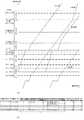
図6(a)は本実施例による画像形成装置による用紙搬送タイミングの例を示すダイヤグラムである。図6(a)は、用紙Aと用紙Bの計2枚の搬送を例として、用紙Aの先端位置(A先端)と後端位置(B後端)、及び用紙Bの先端位置(B先端)と後端位置(B後端)の経過時間による変化を図示している。
先述の制御フローで説明した図3のシーケンス図のステップS1206aによりマスタCPU1001からサブマスタCPU601に給紙開始指示がなされると、ピックアップローラ238により用紙Aの給紙搬送が行われる。本実施例において、給紙搬送速度は、1000mm/sである。<Stepping motor control>
The
<Paper transport timing>
FIG. 6A is a diagram illustrating an example of sheet conveyance timing by the image forming apparatus according to the present embodiment. FIG. 6A shows an example of transporting a total of two sheets of paper A and paper B. The front end position (A front end) and the rear end position (B rear end) of the paper A, and the front end position of the paper B (B front end). ) And the change in the rear end position (B rear end) due to the elapsed time.
When the
用紙Aの先端位置が停止状態のレジストローラ255に到達すると、レジストローラ255の上流側の給紙ローラ対235等は、ループが5mm程度生成されるように搬送を継続し、位置補正が行われる。
用紙Aに印字する画像の形成タイミングに同期してレジストローラ255及びその上流側の給紙ローラ対235等による搬送を再開させる(レジストローラ・オン)。レジストローラ・オン時の速度は1000mm/sである。
2次転写装置231の手前10mmで用紙Aの搬送速度を500mm/sに減速させて画像を用紙Aに転写する。同速度のまま定着を行い、用紙Aの後端が定着ローラ233を抜けた5mm後に1000mm/sに再度加速して排出を行う。When the leading end position of the paper A reaches the stopped
In synchronization with the formation timing of the image to be printed on the paper A, the conveyance by the
The image is transferred to the paper A by reducing the conveyance speed of the paper A to 500 mm / s at 10 mm before the
用紙Bは、レジストローラ255の位置で、先行の用紙Aの後端とぶつからない程度の紙間に調整された状態でピックアップローラ238により給紙搬送を行なう。その後の搬送タイミングは用紙Aと同様であるが、レジストローラ・オンのタイミングで本画像形成装置の生産性を調整する。 The paper B is fed and conveyed by the
図6(b)は搬送パスに関するデータ構造を示している。これらのデータは各サブマスタCPUのフラッシュメモリ(FlashROM)1402に記憶される。用紙搬送に関連するサブマスタCPU601、701、801、902は、各サブマスタCPUが管轄するスレーブCPUにIDを割り当てている。 FIG. 6B shows a data structure related to the transport path. These data are stored in the flash memory (FlashROM) 1402 of each sub-master CPU. The
また、各スレーブCPUによって管轄される搬送パスのパス長とセンサ、ローラ(及びそれを駆動するモータ)、センサ及びローラの搬送パスの入口からの距離が記憶される(図6(b)中の矢印(A)で示す部分)。スレーブCPU602、605、706、802、902のそれぞれによって管轄される搬送パスを、図6(a)に、スレーブCPU毎に示す。各サブマスタCPUは、各スレーブCPUによって管轄される搬送パスの前後関係を結びつける役目も担う。 Further, the path length of the transport path managed by each slave CPU, the sensor, the roller (and the motor that drives it), and the distance from the entrance of the transport path of the sensor and the roller are stored (in FIG. 6B). Part indicated by arrow (A)). The transport paths managed by each of the
<タイミングチャート>
図7は、位置補正(レジストローラ停止)とレジストローラ・オンのタイミングチャートである。なお、用紙はラージサイズ紙でレジ停止及びレジストローラ・オンは同期駆動を行う例が示されている。<Timing chart>
FIG. 7 is a timing chart of position correction (registration roller stop) and registration roller ON. In this example, the paper is a large size paper and the registration stop and the registration roller ON are synchronously driven.
サブマスタCPU601とスレーブCPU602、605の間のローカル通信を用いて停止要求が送受信された後、用紙先端がレジストセンサ256に到達し、信号線1440を介して接続された入力ポートがON(アクティブLow)となる。スレーブCPU602、605は、信号線1440を介して接続された入力ポートを割込みで監視しており、センサONを検知すると、停止要求で受けた要求に基づいてモータ609、610、611、606を停止させる。
所定タイミング後に起動要求に従い、スレーブCPU602、605は、モータ609、610、611,606を起動する。After a stop request is transmitted / received using local communication between the
The
<サブマスタCPUの制御フロー>
次に、サブマスタCPUのCPUコアの処理に関して説明をする。なお、以下の説明において、用紙搬送に関連するサブマスタCPU601、701、801、901及びそれらが管轄するスレーブCPUに共通する処理については符号を省略する。<Control flow of sub-master CPU>
Next, the processing of the CPU core of the sub master CPU will be described. In the following description, reference numerals are omitted for processes common to the
図8(a)は、サブマスタCPUのメインループ処理である。
ステップS1mにおいて、メインバスにコマンドが送信されているか否かを確認し、送信されていればイベント処理A(S2m)を実行する。同様に、ステップS3mでローカル通信にコマンドが送信されているか否かを確認し、送信されていればイベント処理B(S4m)を実行する。FIG. 8A shows the main loop process of the sub-master CPU.
In step S1m, it is confirmed whether or not a command is transmitted to the main bus. If it is transmitted, event processing A (S2m) is executed. Similarly, in step S3m, it is confirmed whether or not a command is transmitted to the local communication. If it is transmitted, event processing B (S4m) is executed.
<メインバスイベント処理>
図8(b)は、メインバスにおけるイベント処理のフローチャートである。マスタCPU1001及び各サブマスタCPU601、701、801、901の間において、予め決めたコマンドフォーマットにしたがってメインバスを経由して送受信されるコマンドを解釈する(S21m)。そして、解釈されたコマンドに従い、各個別の処理(給紙要求:S22m、レジストローラ・オン要求:S23m、紙先端受渡し要求:S24m、紙後端受渡し要求:S25m)を実行する。<Main bus event processing>
FIG. 8B is a flowchart of event processing in the main bus. A command transmitted / received via the main bus is interpreted according to a predetermined command format between the
コマンドが給紙要求の場合(S22m)、スレーブCPU602は紙ID(ここではP)の紙データをSRAM1403上に記録する(S2M06)。ここで、紙データの一例を図10に示す。紙データは紙IDごとに生成され、紙の先端位置及び後端位置、紙サイズ(搬送長さ、幅)、坪量、表面性、先端モータの各情報を含み、制御状態に応じて適宜更新される。尚、図10は、説明のために実際の負荷名を記載しているが、図6(b)で記した負荷ID等を記憶しても良い。 When the command is a paper feed request (S22m), the
コマンドが給紙要求の時点(S26mでYES)において、後に説明する紙Readyフラグをオフにセットしておき、給紙処理を開始する(S27m)。
コマンドがレジストローラ・オン要求の場合(S23mでYES)、レジストローラ・オン処理(S28m)を行う。レジストローラ・オン処理(S28m)の詳細は、イベント処理B(S3M)の後に説明する。When the command is a paper feed request (YES in S26m), a paper ready flag, which will be described later, is set to OFF and paper feed processing is started (S27m).
If the command is a registration roller ON request (YES in S23m), registration roller ON processing (S28m) is performed. Details of the registration roller ON process (S28m) will be described after the event process B (S3M).
コマンドが紙先端受渡し要求の場合(S24mでYES)、紙先端受渡し処理(S29m)を行う。紙先端受渡し処理とは、例えば紙先端が、図6(b)で示したスレーブCPU602の管轄する搬送パスからスレーブCPU605の管轄する搬送パスに突入したことを認識し、スレーブCPU605の搬送負荷を起動する処理である。
コマンドが紙後端受渡し要求の場合(S25mでYES)、紙後端受渡し処理(S30m)を行う。紙後端受渡し処理とは、例えば紙後端が、図6(b)で示したスレーブCPU602の管轄する搬送パスからスレーブCPU605の管轄する搬送パスに突入したことを認識し、スレーブCPU602の搬送負荷を停止する処理である。
先述したとおり、サブマスタCPU601は、図10の紙データにより紙の先端位置及び後端位置を随時算出しており、紙先端受渡し要求(S24m)及び紙後端受渡し要求(S25m)は、後述の紙先端位置処理において内部イベントとして発行される。If the command is a paper tip delivery request (YES in S24m), a paper tip delivery process (S29m) is performed. In the paper leading edge delivery process, for example, it is recognized that the paper leading edge has entered the transport path managed by the
When the command is a paper rear end delivery request (YES in S25m), a paper rear end delivery process (S30m) is performed. For example, the paper trailing edge delivery process recognizes that the paper trailing edge has entered the conveyance path managed by the
As described above, the
<ローカル通信イベント処理>
図8(c)は、図8(a)におけるイベント処理B(S4m)の詳細を表すフローチャートである。本フローチャートでは、スレーブCPUからのタイミングイベントを受けて搬送処理が実行される。<Local communication event processing>
FIG. 8C is a flowchart showing details of the event process B (S4m) in FIG. In this flowchart, the conveyance process is executed in response to a timing event from the slave CPU.
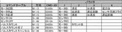
まず、サブマスタ-スレーブCPU間のコマンドフォーマットにしたがって、シリアル通信を通じて受信したコマンドの内容を解析する。図9に、サブマスタCPUとスレーブCPUの間で予め決められたコマンドフォーマットを示す。これらはシリアル通信を通じてやりとりされる。各コマンドにはコマンドID(CMD−ID)が割り振られており、コマンド送信方向が決められている。例えば、モータ起動は、サブマスタCPU(M)からスレーブCPU(S)へのコマンドである。IDは、0100hである。各コマンドは、4個までのパラメタを持ち、モータID、モータ駆動速度(pps単位)、加速度(pps2単位)、電流値(%単位)を各2バイトデータとしてやり取りする。 First, according to the command format between the submaster and slave CPU, the contents of the command received through serial communication are analyzed. FIG. 9 shows a command format predetermined between the sub-master CPU and the slave CPU. These are exchanged through serial communication. A command ID (CMD-ID) is assigned to each command, and the command transmission direction is determined. For example, the motor activation is a command from the sub master CPU (M) to the slave CPU (S). The ID is 0100h. Each command has up to four parameters, and exchanges motor ID, motor driving speed (pps unit), acceleration (pps 2 unit), and current value (% unit) as 2-byte data.
受信したコマンドの内容に従い、紙先端位置更新処理(S41m)、紙先端搬送位置処理(S42m)、紙後端位置更新処理(S43m)を行う。すなわち、紙先端位置更新処理及び紙後端位置更新処理の各々において、センサの検知コマンド(0900h、0910h)、信号及びモータの駆動パルスカウントコマンド(0A00h,0B00h)を用いて、先端位置および後端位置を更新する。 In accordance with the contents of the received command, a paper leading edge position updating process (S41m), a paper leading edge transport position process (S42m), and a paper trailing edge position updating process (S43m) are performed. That is, in each of the paper leading edge position updating process and the paper trailing edge position updating process, the leading edge position and trailing edge are detected by using sensor detection commands (0900h, 0910h), signals and motor drive pulse count commands (0A00h, 0B00h). Update position.
<位置補正(レジ停止)処理>
紙先端搬送位置処理は、搬送パスにおけるあらゆるイベントに関する処理であるが、サブマスタCPUごとに異なる内容となる。図8(d)に示されたフローチャートは、サブマスタCPU601によって実行される。なお、用紙の先端位置は先に説明した紙先端位置更新処理(S41m)で認識可能である。<Position correction (registration stop) processing>
The paper leading edge transport position process is a process related to every event in the transport path, but has different contents for each sub-master CPU. The flowchart shown in FIG. 8D is executed by the
用紙の先端がピックアップローラ238から240mmの位置(即ち、レジストセンサ256の位置)に到達した場合(S421mでYES)、位置補正のためにレジ停止要求を行う(S422m)。
用紙先端がピックアップローラ238から260mmの位置(即ちレジ停止位置)に到達した場合(S423mでYES)、紙ReadyフラグをONにセットする(S424m)。ここで紙Readyフラグは、用紙が位置補正のためにレジ停止位置に到達したことを示すフラグであり、印字画像に同期してレジストローラをオンにして良いことを示す。When the leading edge of the paper reaches a position of 240 mm from the pickup roller 238 (that is, the position of the registration sensor 256) (YES in S421m), a registration stop request is made for position correction (S422m).
When the leading edge of the paper reaches a
<レジ停止要求処理>
図8(e)は、レジ停止要求処理を表すフローチャートである。これまでのフローチャートで随時更新してきた図10における紙データを参照し、用紙の先端管轄スレーブID(N1)と後端管轄スレーブID(N2)の間の全てのスレーブCPUに対して、停止要求を送信する(S4221m)。スレーブCPU(ID=N1〜N2)に停止要求(モータ停止:0200h)を送信する。<Registration stop request processing>
FIG. 8E is a flowchart showing the registration stop request process. With reference to the paper data in FIG. 10 updated as needed in the flowcharts so far, a stop request is issued to all slave CPUs between the leading edge slave ID (N1) and trailing edge slave ID (N2) of the sheet. Transmit (S4221m). A stop request (motor stop: 0200h) is transmitted to the slave CPU (ID = N1 to N2).
<レジストローラ・オン処理>
図8(f)は、図8(b)におけるレジストローラ・オン処理(S28m)のフローチャートである。図10における紙データを参照し、用紙の先端管轄スレーブID(N1)と後端管轄スレーブID(N2)の間の全てのスレーブCPUに対して、起動要求を送信する(S281m)。すなわち、スレーブCPU(ID=N1〜N2)に起動要求(モータ起動:0100h)を送信する。<Registration roller ON processing>
FIG. 8F is a flowchart of the registration roller ON process (S28m) in FIG. Referring to the paper data in FIG. 10, the activation request is transmitted to all the slave CPUs between the leading edge slave ID (N1) and the trailing edge slave ID (N2) of the paper (S281m). That is, an activation request (motor activation: 0100h) is transmitted to the slave CPU (ID = N1 to N2).
以上のように、位置補正(レジ停止)及びレジストローラ・オンに関して、複数のスレーブCPUで同期したモータ制御を行う例を説明した。しかし、2次転写前の減速や定着後の増速などにおいても、ほぼ同様のフローにて同期・非同期によるモータ駆動を行うことができる。 As described above, the example of performing the motor control synchronized with the plurality of slave CPUs with respect to the position correction (registration stop) and the registration roller ON has been described. However, even in deceleration before secondary transfer and acceleration after fixing, the motor can be driven synchronously and asynchronously with substantially the same flow.
<スレーブCPUの制御フロー>
図11(a)は、スレーブCPUのメインループ処理のフローチャートである。スレーブCPUは、ローカル通信であるシリアル通信I/F1407を監視し、サブマスタCPUからのコマンドを待機する(S1n)。ステップS1nにおいてコマンドイベントが発生した場合、イベント処理C(S2n)を行う。<Slave CPU control flow>
FIG. 11A is a flowchart of the main loop process of the slave CPU. The slave CPU monitors the serial communication I /
イベント処理Cにおいては、図11(b)に示されたように、シリアル通信I/F1407の得たコマンドを解析する(S21n)。モータ起動要求(S22n)、モータ停止要求(S23n)、モータ変速要求(S24n)、モータパルスカウント要求(S25n)、モータパルスカウントキャンセル要求(S26n)のそれぞれの処理へ分岐する。そしてそれぞれのコマンドに対する処理(S27n、S28n、S29n、S30n、S31n)を行う。センサ割込み処理の詳細は後述する。 In the event process C, as shown in FIG. 11B, the command obtained by the serial communication I /
<ステッピングモータ制御状態の遷移>
図12は、前述のイベント処理S2nを受けた場合の、ステッピングモータ制御状態の遷移を示した状態遷移チャートである。
図12において、状態(ST_SLxx)は円形ブロックで表記され、コマンド及びコマンドを受けた際のアクション(ACT_SLxx)は矢印及び文字列にて表記されている。実線の上側の文字列はコマンド、実線の下側の文字列はアクションをそれぞれ示している。<Transition of stepping motor control state>
FIG. 12 is a state transition chart showing the transition of the stepping motor control state when the event process S2n is received.
In FIG. 12, a state (ST_SLxx) is represented by a circular block, and a command and an action (ACT_SLxx) upon receiving the command are represented by an arrow and a character string. The character string above the solid line indicates a command, and the character string below the solid line indicates an action.
まずスレーブCPUのパワーオンリセット状態で停止状態ST_SL01から、処理が開始する。この時点ではステッピングモータのパルス及び励磁はOFFである。停止状態ST_SL01でモータ起動(0100h)を受信すると(ACT_SL01)、ステッピングモータの励磁をONし、制御状態は例えば50msのホールド状態ST_SL02に遷移する。
ホールド状態が解除され、若しくは再びモータ起動(0100h)を受信すると(ACT_SL03)、PWM生成器1410の出力イネーブルをオンにしてモータを起動し、制御状態は加速状態ST_SL03に遷移する。First, the process starts from the stop state ST_SL01 in the power-on reset state of the slave CPU. At this time, the pulse and excitation of the stepping motor are OFF. When the motor activation (0100h) is received in the stop state ST_SL01 (ACT_SL01), the excitation of the stepping motor is turned on, and the control state transitions to the hold state ST_SL02 of 50 ms, for example.
When the hold state is released or the motor activation (0100h) is received again (ACT_SL03), the output enable of the
PWM生成器1410の出力周期が目標速度に相当する周期に到達すると(ACT_SL04)、制御状態は定速搬送状態ST_SL04に遷移する。
定速搬送状態ST_SL04で変速要求(0300h)を受信すると、制御状態は加速状態若しくは減速状態に遷移する。すなわち、現在の速度より加速する場合は(ACT_SL06)、制御状態は加速状態ST_SL03に遷移し、PWM生成器1410の周期を変更する。現在の速度より減速する場合は(ACT_SL09)、制御状態は減速状態ST_SL05に遷移する。
定速搬送状態ST_SL04で停止要求(0200h、センサ同期フラグOFF)を受信すると(ACT_SL10)、制御状態は減速状態ST_SL05に遷移する。PWM生成器1410による出力が停止したら(ACT_SL07)、制御状態はホールド状態ST_SL02に遷移する。When the output cycle of the
When a shift request (0300h) is received in the constant speed conveyance state ST_SL04, the control state transitions to an acceleration state or a deceleration state. That is, when accelerating from the current speed (ACT_SL06), the control state transitions to the acceleration state ST_SL03, and the period of the
When a stop request (0200h, sensor synchronization flag OFF) is received in the constant speed conveyance state ST_SL04 (ACT_SL10), the control state transitions to the deceleration state ST_SL05. When the output from the
ホールド状態ST_SL02において、例えば、50ms待った後に励磁をOFFし(ACT_SL02)、制御状態は、停止状態ST_SL01に遷移する。
定速搬送状態ST_SL04において、センサ同期フラグONの停止要求(0200h)を受信すると(ACT_SL08)、同期停止指定フラグをON及びセンサ割込みマスクを解除して、定速搬送状態ST_SL04のまま、センサ入力を待機する。In the hold state ST_SL02, for example, after waiting for 50 ms, the excitation is turned off (ACT_SL02), and the control state transitions to the stop state ST_SL01.
When the sensor synchronization flag ON stop request (0200h) is received in the constant speed conveyance state ST_SL04 (ACT_SL08), the synchronization stop designation flag is turned ON and the sensor interrupt mask is canceled, and the sensor input is kept in the constant speed conveyance state ST_SL04. stand by.
図12の状態遷移チャートにおいて、パルスカウント要求及びパルスカウントキャンセル要求の記載は省略されているが、基本的な処理は上述の処理に準ずる。例えば、加速状態ST_SL03、定速搬送状態ST_SL04、減速状態ST_SL05にてパルスカウント要求(0A00h)を受信して、PWM生成器1410の出力するパルス数をカウントする。カウント終了で発生する割り込みでパルスカウント終了(0B00h)を通知する。 In the state transition chart of FIG. 12, the description of the pulse count request and the pulse count cancel request is omitted, but the basic processing is in accordance with the above processing. For example, the pulse count request (0A00h) is received in the acceleration state ST_SL03, the constant speed conveyance state ST_SL04, and the deceleration state ST_SL05, and the number of pulses output from the
<センサ割込み処理>
続いて、センサ割込み処理を図11(c)のフローチャートを参照しながら説明する。
図12のACT_SL08でセットされる同期停止フラグがONならば(S3nでYES)、同期停止指定フラグをOFFにセットして、指定パルス数でのモータ停止を行う(S4n)。そして、センサ割込みをマスクする(S5n)。<Sensor interrupt processing>
Next, sensor interrupt processing will be described with reference to the flowchart of FIG.
If the synchronous stop flag set in ACT_SL08 in FIG. 12 is ON (YES in S3n), the synchronous stop designation flag is set to OFF and the motor is stopped at the designated number of pulses (S4n). Then, the sensor interrupt is masked (S5n).
<サブマスタCPU−スレーブCPU間のイベントシーケンス>
図13は、給紙開始から、位置補正(レジ停止)、レジストローラ・オンに至るまでの一連の動作における、サブマスタCPU601、スレーブCPU602、605の間の通信イベントシーケンスである。各イベントにおいて先に述べたフローチャート内の処理に対応する通信イベントの一部が示されている。なお、用紙は、ラージサイズ紙であり、レジ停止及びレジストローラ・オンは、同期駆動を行う例である。ここで、ラージサイズ紙とは、例えば、スレーブCPU605が管轄する搬送パスの長さである220mmより搬送長が長い紙で、例えば、A3サイズ紙である。<Event sequence between sub-master CPU and slave CPU>
FIG. 13 shows a communication event sequence between the
マスタCPU1001よりサブマスタCPU601に対して給紙要求が出されると(S27m)、サブマスタCPU601は、スレーブCPU602にモータ606を起動させ、ピックアップローラ238を駆動することで給紙動作を行なう。略同時に、サブマスタCPU601は、センサ247の遅延ジャム検知を開始する。
紙先端がセンサ247に到達し、センサオンのコマンドがスレーブCPU602からサブマスタCPU601に送信されると、紙先端位置更新処理(S41m)でモータ606のパルスカウントをキャンセルして、遅延ジャム検知を停止させる。When the
When the leading edge of the paper reaches the
引き続きモータ606のパルスカウントを行い、用紙先端がスレーブCPU602の管轄する搬送パスの出口に到達するタイミングを得る。
モータ606のパルスカウント終了により、サブマスタCPU601は、紙先端位置更新処理(S41m)を行い、それを受けて紙先端出口処理S29mを行う。用紙先端は、スレーブCPU605の管轄する搬送パスに突入するため、スレーブCPU605の持つモータ609、610、611に起動要求(モータ起動:0100h)をかける。Subsequently, the pulse count of the motor 606 is performed to obtain the timing at which the leading edge of the sheet reaches the exit of the conveyance path managed by the
Upon completion of the pulse count of the motor 606, the
その後も紙先端位置更新処理(S41m)を繰り返して、紙先端がレジストセンサ256の手前20mmに到達すると紙先端位置処理(S42m)及びレジ停止要求処理(S422m)が実行される。サブマスタCPU601から停止要求(モータ停止:0200h)がスレーブCPU602、605に送信される。
レジストセンサ256に紙先端が到達すると信号線1440を通じてスレーブCPU602、605に同期割込みが発生し、スレーブCPU605は予め停止要求で受信していた停止パルス数でモータ609、610、611、606を停止させる。
その後、マスタCPU1001よりレジストローラ・オン要求が到来するとレジストローラ・オン処理S28mを行い、スレーブCPU602、605に対して起動要求(モータ起動:0100h)を送信し、レジストローラが駆動される。Thereafter, the paper leading edge position update process (S41m) is repeated, and when the paper leading edge reaches 20 mm before the
When the leading edge of the paper reaches the
Thereafter, when a registration roller ON request is received from the
以上説明したように、本実施例は、媒体搬送を複数の制御部による通信ネットワークにて同期して行う媒体搬送装置において有効である。 As described above, the present embodiment is effective in a medium transport apparatus that performs medium transport in synchronization with a communication network formed by a plurality of control units.
235、236、237:給紙ローラ対(第2搬送手段)
238:ピックアップローラ(第1搬送手段)
256:レジストセンサ(媒体検知手段)
601:サブマスタCPU(上層制御手段、統括同期駆動指示手段)
602:スレーブCPU(第1下層制御手段)
605:スレーブCPU(第2下層制御手段)
606:駆動源モータ(第1搬送手段)
609、610、611:ステッピングモータ(第2搬送手段)
612、615:シリアル通信(通信手段)
1000:媒体搬送装置235, 236, 237: paper feed roller pair (second conveying means)
238: Pickup roller (first conveying means)
256: Registration sensor (medium detection means)
601: Submaster CPU (upper layer control means, overall synchronous drive instruction means)
602: Slave CPU (first lower layer control means)
605: Slave CPU (second lower layer control means)
606: Drive source motor (first transport means)
609, 610, 611: Stepping motor (second conveying means)
612, 615: Serial communication (communication means)
1000: Medium transport device
Claims (4)
Translated fromJapanese媒体を搬送する第1搬送手段と、
前記第1搬送手段を制御する第1下層制御手段と、
前記第1搬送手段により搬送された媒体を受け取り、受け取った媒体を搬送する第2搬送手段と、
前記第2搬送手段を制御する第2下層制御手段と、
前記第1下層制御手段および前記第2下層制御手段を統括的に制御する上層制御手段と、
前記第1下層制御手段および前記第2下層制御手段に接続された媒体検知手段と
を有し、
前記第1下層制御手段および前記第2下層制御手段は、前記媒体検知手段からの信号に基づいて同期して前記第1搬送手段および前記第2搬送手段を制御する同期駆動を行うことを特徴とした媒体搬送装置。A medium carrying device for carrying a medium,
First conveying means for conveying a medium;
First lower layer control means for controlling the first transport means;
A second conveying means for receiving the medium conveyed by the first conveying means and conveying the received medium;
Second lower layer control means for controlling the second transport means;
Upper layer control means for comprehensively controlling the first lower layer control means and the second lower layer control means;
Medium detection means connected to the first lower layer control means and the second lower layer control means,
The first lower layer control means and the second lower layer control means perform synchronous driving for controlling the first conveyance means and the second conveyance means in synchronization based on a signal from the medium detection means. Media transport device.
Priority Applications (1)
| Application Number | Priority Date | Filing Date | Title |
|---|---|---|---|
| JP2010281427AJP2012126546A (en) | 2010-12-17 | 2010-12-17 | Medium transport apparatus |
Applications Claiming Priority (1)
| Application Number | Priority Date | Filing Date | Title |
|---|---|---|---|
| JP2010281427AJP2012126546A (en) | 2010-12-17 | 2010-12-17 | Medium transport apparatus |
Publications (1)
| Publication Number | Publication Date |
|---|---|
| JP2012126546Atrue JP2012126546A (en) | 2012-07-05 |
Family
ID=46644034
Family Applications (1)
| Application Number | Title | Priority Date | Filing Date |
|---|---|---|---|
| JP2010281427APendingJP2012126546A (en) | 2010-12-17 | 2010-12-17 | Medium transport apparatus |
Country Status (1)
| Country | Link |
|---|---|
| JP (1) | JP2012126546A (en) |
Cited By (3)
| Publication number | Priority date | Publication date | Assignee | Title |
|---|---|---|---|---|
| CN103777613A (en)* | 2014-01-26 | 2014-05-07 | 广州广电运通金融电子股份有限公司 | Master-slave information real-time interaction method and system |
| CN109671210A (en)* | 2017-10-13 | 2019-04-23 | 创新技术有限公司 | Modular bill equipment |
| JP2022114431A (en)* | 2021-01-26 | 2022-08-05 | キヤノン株式会社 | image forming device |
Citations (3)
| Publication number | Priority date | Publication date | Assignee | Title |
|---|---|---|---|---|
| JPH05306038A (en)* | 1992-04-30 | 1993-11-19 | Shinko Electric Co Ltd | Transport roll driving device for transporting sheet, etc. |
| JPH08336189A (en)* | 1995-06-09 | 1996-12-17 | Ricoh Co Ltd | Image forming device |
| JP2003063698A (en)* | 2001-08-24 | 2003-03-05 | Fuji Xerox Co Ltd | Carrying device |
- 2010
- 2010-12-17JPJP2010281427Apatent/JP2012126546A/enactivePending
Patent Citations (3)
| Publication number | Priority date | Publication date | Assignee | Title |
|---|---|---|---|---|
| JPH05306038A (en)* | 1992-04-30 | 1993-11-19 | Shinko Electric Co Ltd | Transport roll driving device for transporting sheet, etc. |
| JPH08336189A (en)* | 1995-06-09 | 1996-12-17 | Ricoh Co Ltd | Image forming device |
| JP2003063698A (en)* | 2001-08-24 | 2003-03-05 | Fuji Xerox Co Ltd | Carrying device |
Cited By (5)
| Publication number | Priority date | Publication date | Assignee | Title |
|---|---|---|---|---|
| CN103777613A (en)* | 2014-01-26 | 2014-05-07 | 广州广电运通金融电子股份有限公司 | Master-slave information real-time interaction method and system |
| CN103777613B (en)* | 2014-01-26 | 2016-08-24 | 广州广电运通金融电子股份有限公司 | Principal and subordinate's information realtime interactive method and system |
| US9823650B2 (en) | 2014-01-26 | 2017-11-21 | Grg Banking Equipment Co., Ltd. | Method and system for interacting master and slave information in real time |
| CN109671210A (en)* | 2017-10-13 | 2019-04-23 | 创新技术有限公司 | Modular bill equipment |
| JP2022114431A (en)* | 2021-01-26 | 2022-08-05 | キヤノン株式会社 | image forming device |
Similar Documents
| Publication | Publication Date | Title |
|---|---|---|
| JP5646866B2 (en) | Medium transport device | |
| US7486902B2 (en) | Image fixing apparatus and image forming apparatus | |
| JP5460084B2 (en) | Image forming apparatus | |
| JP2825846B2 (en) | Sheet transport device in double-sided image recording device | |
| US8744335B2 (en) | Image forming apparatus improved in operability for print job involving single-sided printing and double-sided printing | |
| JP2015049444A (en) | Image forming system and control method thereof | |
| US6322069B1 (en) | Interpaper spacing control in a media handling system | |
| JP6587665B2 (en) | Image forming apparatus | |
| JP5610799B2 (en) | Image forming apparatus | |
| JP2012126546A (en) | Medium transport apparatus | |
| JP4138135B2 (en) | Copy sheet movement control method | |
| JP2002173252A (en) | Image forming device and control method thereof | |
| JP2013249177A (en) | Image forming apparatus and sheet feeding apparatus | |
| JP4407149B2 (en) | Sheet conveying apparatus and image forming apparatus | |
| JP2014046466A (en) | Image forming apparatus and control method thereof, and program | |
| JPH05538A (en) | Image forming system | |
| JP2010256566A (en) | Image forming apparatus | |
| JP2002104697A (en) | Image forming device | |
| JP7612321B2 (en) | Sheet processing apparatus and image forming system | |
| JPH0412946A (en) | Image forming device | |
| JP2004001972A (en) | Double-side printer | |
| JP2000318245A (en) | Method and apparatus for controlling sheet cut length for web type electronic printing machine | |
| JP2593270Y2 (en) | Image forming device | |
| JP2010215387A (en) | Paper feeding mechanism and paper feeding method in printer | |
| JPH0844250A (en) | Image forming apparatus and control method thereof |
Legal Events
| Date | Code | Title | Description |
|---|---|---|---|
| RD05 | Notification of revocation of power of attorney | Free format text:JAPANESE INTERMEDIATE CODE: A7425 Effective date:20120730 | |
| RD05 | Notification of revocation of power of attorney | Free format text:JAPANESE INTERMEDIATE CODE: A7425 Effective date:20120731 | |
| RD03 | Notification of appointment of power of attorney | Free format text:JAPANESE INTERMEDIATE CODE: A7423 Effective date:20120831 | |
| RD05 | Notification of revocation of power of attorney | Free format text:JAPANESE INTERMEDIATE CODE: A7425 Effective date:20130701 | |
| A621 | Written request for application examination | Free format text:JAPANESE INTERMEDIATE CODE: A621 Effective date:20131213 | |
| A977 | Report on retrieval | Free format text:JAPANESE INTERMEDIATE CODE: A971007 Effective date:20140804 | |
| A131 | Notification of reasons for refusal | Free format text:JAPANESE INTERMEDIATE CODE: A131 Effective date:20140807 | |
| A521 | Written amendment | Free format text:JAPANESE INTERMEDIATE CODE: A523 Effective date:20141006 | |
| A02 | Decision of refusal | Free format text:JAPANESE INTERMEDIATE CODE: A02 Effective date:20150113 |