JP2012122477A - Drag type windmill and wind power generation apparatus - Google Patents
Drag type windmill and wind power generation apparatusDownload PDFInfo
- Publication number
- JP2012122477A JP2012122477AJP2011242109AJP2011242109AJP2012122477AJP 2012122477 AJP2012122477 AJP 2012122477AJP 2011242109 AJP2011242109 AJP 2011242109AJP 2011242109 AJP2011242109 AJP 2011242109AJP 2012122477 AJP2012122477 AJP 2012122477A
- Authority
- JP
- Japan
- Prior art keywords
- paddle
- wind
- windmill
- wind turbine
- drag type
- Prior art date
- Legal status (The legal status is an assumption and is not a legal conclusion. Google has not performed a legal analysis and makes no representation as to the accuracy of the status listed.)
- Pending
Links
- 238000010248power generationMethods0.000titledescription7
- 230000002093peripheral effectEffects0.000claimsabstractdescription18
- 238000002474experimental methodMethods0.000description4
- 238000005192partitionMethods0.000description3
- 238000007664blowingMethods0.000description2
- 238000001816coolingMethods0.000description2
- 230000005611electricityEffects0.000description2
- 230000001141propulsive effectEffects0.000description2
- 230000003014reinforcing effectEffects0.000description2
- 230000000694effectsEffects0.000description1
- 238000012423maintenanceMethods0.000description1
Images


Classifications
- Y—GENERAL TAGGING OF NEW TECHNOLOGICAL DEVELOPMENTS; GENERAL TAGGING OF CROSS-SECTIONAL TECHNOLOGIES SPANNING OVER SEVERAL SECTIONS OF THE IPC; TECHNICAL SUBJECTS COVERED BY FORMER USPC CROSS-REFERENCE ART COLLECTIONS [XRACs] AND DIGESTS
- Y02—TECHNOLOGIES OR APPLICATIONS FOR MITIGATION OR ADAPTATION AGAINST CLIMATE CHANGE
- Y02E—REDUCTION OF GREENHOUSE GAS [GHG] EMISSIONS, RELATED TO ENERGY GENERATION, TRANSMISSION OR DISTRIBUTION
- Y02E10/00—Energy generation through renewable energy sources
- Y02E10/70—Wind energy
- Y02E10/74—Wind turbines with rotation axis perpendicular to the wind direction
Landscapes
- Wind Motors (AREA)
Abstract
Translated fromJapaneseDescription
Translated fromJapaneseこの発明は、複数の風受け用のパドルを設け、パドルと一体的に回転する縦に配置されたロータ軸を設けた抗力型の風車であって、パドルの公転内側に風圧ガイドを設け、パドルが効率よく回転する抗力型風車と、それを利用した風力発電装置に関する。The present invention provides a drag-type windmill provided with a plurality of wind-receiving paddles and provided with a vertically disposed rotor shaft that rotates integrally with the paddles. TECHNICAL FIELD The present invention relates to a drag type wind turbine that efficiently rotates and a wind power generator using the drag type wind turbine.
従来、垂直軸回転型の抗力型風車は、水平軸回転型風車の一つであるプロペラ型の風車と違って、風が吹く方角に応じて風車の方向(風受け体勢)を変える必要がなく、その構造が簡単である。また、設置や運転方法も容易であることから、小型動力源、例えば小型発電装置等に利用されてきた。その構造については、回転の中心となるロータ軸の周囲に複数のパドル(又はブレード)と称される風受けを配設し、このパドルで受けた風の力をロータ軸の回転力として利用するものであった。Unlike conventional propeller type wind turbines, which are one of the horizontal axis rotary type wind turbines, there is no need to change the direction of the wind turbine (wind receiving posture) according to the direction of the wind. The structure is simple. In addition, since it is easy to install and operate, it has been used for small power sources such as small power generators. As for the structure, a plurality of paddles (or blades) called paddles (or blades) are arranged around the rotor shaft that is the center of rotation, and the wind force received by these paddles is used as the rotational force of the rotor shaft. It was a thing.
抗力型風車の複数のパドルは、一般的にロータ軸を中心に等間隔に配列されている。各パドルは風が当たる方角(部位)の違いでパドル前後の風力抵抗が異なる。例えば、風上側(逆風側)に位置するパドルの凸部形状である前面の抵抗が小さくなるようにパドル形状が取られている。つまり、各パドルについてみると、その凸状前面と風を受け入れる凹状後面とでは、風に対する抗力(係数)が異なる。回転する前面側である前凸部では風の抵抗は小であり、後面側の風受部では風力抵抗が大になるような形状となっている。従来の抗力型風車では、パドル前後面の抗力差を得る手段として、パドル前面を円弧形ないし、やや湾曲形に形成していた。The plurality of paddles of the drag type wind turbine are generally arranged at equal intervals around the rotor shaft. Each paddle has different wind resistance before and after the paddle depending on the direction (part) where the wind hits. For example, the paddle shape is taken so that the resistance of the front surface which is the convex shape of the paddle located on the windward side (back wind side) is reduced. That is, regarding each paddle, the resistance (coefficient) against the wind differs between the convex front surface and the concave rear surface that receives the wind. Wind resistance is small at the front convex part which is the front side rotating, and the wind resistance is large at the wind receiving part on the rear side. In the conventional drag type windmill, as a means for obtaining a drag difference between the front and rear surfaces of the paddle, the front surface of the paddle is formed in an arc shape or a slightly curved shape.
従来例である特許文献1では、風杯(パドル)に当たる風の力を効率的に得るために、風杯の公転外周側に放射状に風を導く案内羽根を設けたものである。この従来例では、風車全体の外形寸法は大きく、構造が複雑となり、装置のコストや風杯の保守等に課題があった。また他の従来例である特許文献2では、パドルの形状や隣接するパドルの配置や方向関係等を工夫して、パドルが風下側に位置するときにパドル受風部に、より風が当たるよう隣接するパドルをより接近する工夫がなされている。この例でも、パドルの構造や形状は複雑となる。また風上に位置する戻り側の反対の位置では、パドル前面の隣接している重なり部分が大きくなり、風の抗力が増大する課題があった。In
従来の抗力型風車の例として、図11に概略的な構造を示す。風車の中心に設けられたロータ軸52を中心に放射状に伸びている支持腕54を介して等間隔に配置されているパドル51(a)〜51(d)で風を受け、ロータ軸52にその回転力が付与される。各パドル51は水平断面が円弧形又は湾曲形の断面形状であって、風に対して風を受け入れる側(駆動側)に位置する後方の風受部パドル51(a)で風を大きく受ける。これに対して、風上側にパドルの凸部前面を向けているパドル51(c)では、風の抵抗が後方の風受部51(a)より小さい。このパドル前後の風受部の抗力差によりロータ軸52に回転力が付与され、ロータ軸52を介して風車全体が回転する。FIG. 11 shows a schematic structure as an example of a conventional drag type wind turbine. The
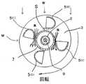
上記のような従来の抗力型風車は、風の方角に拘わらず抗力差が得られるが、本出願人は図1、図2に示すように、風圧ガイド7をパドル5の公転内側に設け、風下に位置する駆動側のパドルへの風の流れを風圧ガイドにより効力的に集めると共に、風上に位置する戻り側のパドルは、パドルと風圧ガイドの隙間Sを設けることで風の抵抗を少なくできるのではないかと考えた。すなわち、風を後方から 受けて進むパドル5(a)はより風を受け、風上に向かうパドル5(c)の方は、その内周外縁と風圧ガイドの隙間Sに風が通過する際に急速に絞られ流速を増してその位置で負圧が生じ、風の抵抗がより小さくなり、パドル間の効力差が各段に大きくなり回転力を高めることができると考えた。In the conventional drag type windmill as described above, a drag difference can be obtained regardless of the direction of the wind. However, as shown in FIGS. 1 and 2, the present applicant provides a
また、パドル5の外周外縁端の延長上に、翼19を突設することにより、風Wを確実に捉えて風力を有効に利用し回転力を大きく得ることができるとともに、風受部側5(a)で発生する風の渦(出入りする風の衝突等による)による乱流の影響を少なくすることで、より安定して回転力を維持することができるとも着想し、数値解析と風洞実験を行った。Further, by providing the
つまり、この発明は、パドル5の前後の風の空気抵抗の差(抗力差)をより大きくすることにより、さらに効率的に風車を回転することができる抗力型風車を提供することを課題とした。That is, an object of the present invention is to provide a drag-type windmill that can rotate the windmill more efficiently by increasing the difference in air resistance between the winds before and after the paddle 5 (drag difference). .
また、パドル5の外周外縁端に翼19を設け、風の力を回転力として得ることができるとともに、この翼に太陽電池Pを設けることにより、風の弱い日でも太陽光により発電できる風力発電装置を提供できると考えた。Wind power generation that can generate wind power by using sunlight even on a weak day can be obtained by providing a
上記の課題を解決するために、この発明は、抗力型風車Mの中心Oに回転可能に設けられたロータ軸9と同芯の風圧ガイド7と、水平断面の形状が楕円や楕円形に類似の近似楕円の約半分である仮想半楕円形状からなる複数のパドル5を風圧ガイドの外周に公転可能に設け、風圧ガイドにより、風の流れは駆動側のパドルにより多く集められ、一方、風圧ガイドの外周と各パドルの内周側縁との間に空気の流れ(絞り)が生じて空気の負圧が発生する隙間を設けた。In order to solve the above-described problems, the present invention is similar to a
この構成によれば、水平断面が仮想半楕円形状の凸部で風を受けることで風の抵抗が小さくなる。また風から受ける力は、後方の風受け側でより風圧ガイドにより効率的に集められる。この抗力差によって抗力型風車は効率よく回転する。さらに、パドルの公転の内側(風車中心O側)である内周側と風圧ガイド外周とで形成される隙間に入り込む風が絞られて負圧が生じ、パドル側面側の空気抵抗が小さくなり、パドル前後の抗力差がさらに大きくなることが数値解析と実験で確認された。According to this configuration, the wind resistance is reduced by receiving the wind at the convex part having a virtual semi-elliptical horizontal cross section. Further, the force received from the wind is more efficiently collected by the wind pressure guide on the rear wind receiving side. Due to this drag difference, the drag type wind turbine rotates efficiently. Furthermore, the wind that enters the gap formed between the inner periphery side of the paddle revolution (the windmill center O side) and the outer periphery of the wind pressure guide is squeezed, negative pressure is generated, and the air resistance on the side surface of the paddle is reduced. It was confirmed by numerical analysis and experiment that the drag difference before and after the paddle was further increased.
また第2の解決手段は、風車の中心Oを芯として回転可能な天板と底板とを設け、両板とパドルを固定したものである。この構成によれば、風車の中心に回転する天板と底板との間に各パドルを一体的に固定したことで、より剛性のあるパドルの構造を得ることができる。In the second solution, a top plate and a bottom plate that are rotatable about the center O of the windmill are provided, and both the plates and the paddle are fixed. According to this configuration, since each paddle is integrally fixed between the top plate and the bottom plate rotating at the center of the windmill, a more rigid paddle structure can be obtained.
また第3の解決手段は、各パドルと天板・底板との取付位置及び、または取付角度を調整自在にしたものである。この構造によれば、風車を設置する環境に応じて最適なパドルと風圧ガイドとの隙間やパドルの姿勢を個々に調整することができる。The third solving means is such that the mounting position and / or mounting angle of each paddle and the top / bottom plate can be adjusted. According to this structure, the optimal gap between the paddle and the wind pressure guide and the posture of the paddle can be individually adjusted according to the environment in which the windmill is installed.
また第4の解決手段は、各パドルの水平断面の仮想半楕円形状の短軸に対する長軸の比率が、2.5〜3.5にしたものである。この形状によって、パドル前凸部の空気抵抗が小さくなり、パドル前後の抗力差が大となり、効率的な回転力を得ることができることが実験から得られた。In the fourth solution, the ratio of the major axis to the minor axis of the virtual semi-elliptical shape in the horizontal section of each paddle is 2.5 to 3.5. It has been experimentally obtained that, due to this shape, the air resistance of the front projection of the paddle is reduced, the drag difference between the front and rear of the paddle is increased, and an efficient rotational force can be obtained.
また第5の解決手段は、天板と底板とに対して各パドルが風車の中心方向に傾斜する取付角度であり、風圧ガイドの外周は各パドルの傾斜角度とやや平行な円錐形状で、かつ風圧ガイドの外周と各パドル内周側縁との間に隙間を設けたものである。この構成により、風車の高さを低く抑えることができる。The fifth solving means is an attachment angle in which each paddle is inclined in the center direction of the windmill with respect to the top plate and the bottom plate, and the outer periphery of the wind pressure guide has a conical shape slightly parallel to the inclination angle of each paddle, and A gap is provided between the outer periphery of the wind pressure guide and the inner peripheral edge of each paddle. With this configuration, the height of the windmill can be kept low.
また第6の解決手段は、各パドル後方の風受部を閉じた形状にしたものである。パドルの後方の風受部を閉じた形状にすることにより、パドル後方に開口した風受部の場合に比べて風から受ける抗力は大きくなると共に、後方が開いているパドルでは出入する風が衝突し、その際に発生する風の渦を少なくすることで風の乱流の発生を防止し、より安定した回転力を維持することができることが実験で確認された。In the sixth solution, the wind receiving portion behind each paddle is closed. By making the wind receiver at the back of the paddle closed, the drag received from the wind is greater than in the case of the wind receiver opening at the rear of the paddle, and the wind entering and exiting the paddle with the rear open In experiments, it was confirmed that by reducing the vortex of the wind generated at that time, the generation of the turbulence of the wind can be prevented and a more stable rotational force can be maintained.
また第7の解決手段は、各パドルの外周外縁端に翼を風車中心側にやや傾斜した状態で突設したものである。これによれば、風が翼の横方向から受けた場合は、中心側に傾斜した翼の形状により回転方向に推進力が得られる。また翼により風を逃がさないで確実に捉えることができ、風の力を有効に得ることができる。In the seventh solution, a blade is protruded from the outer peripheral edge of each paddle in a slightly inclined state toward the windmill center. According to this, when the wind is received from the lateral direction of the wing, a propulsive force is obtained in the rotational direction due to the shape of the wing inclined toward the center. In addition, the wings can reliably catch the wind without escaping, and the wind force can be obtained effectively.
また第8の解決手段は、各パドルや翼の表面に太陽電池を設けたものである。この構成によれば、パドルや翼に太陽電池を設けることで、風のない日でも太陽光により発電することができる。また、太陽電池を回転するパドルに設けることで、風の冷却効果で太陽電池が高熱になることを防止し、電池の発電効率の低下を防ぐことができる。In the eighth solution, a solar cell is provided on the surface of each paddle or wing. According to this configuration, by providing solar cells on the paddles and wings, power can be generated by sunlight even on days without wind. Moreover, by providing the solar cell on the rotating paddle, it is possible to prevent the solar cell from becoming hot due to the cooling effect of the wind, and to prevent the power generation efficiency of the battery from being lowered.
また第9の解決手段は、各パドル及び、又は翼の内周部に天板・底板とに平行に設けられた風圧セパレータを設けたものである。パドルや翼の内周部に風圧セパレータを設けることで、パドルや翼に受けた風を上下左右に逃げることなく確実に捉えることができる。またパドルや翼の剛性を高めることができる。In the ninth solution, a wind pressure separator provided in parallel with the top plate and the bottom plate is provided on the inner periphery of each paddle and / or wing. By providing a wind pressure separator on the inner periphery of the paddle or wing, the wind received by the paddle or wing can be reliably captured without escaping up and down and left and right. In addition, the rigidity of the paddle and wing can be increased.
また第10の解決手段は、上下複数段からなる抗力型風車において、最上段の風車の各パドルは風車中心に傾斜する取付角度で、かつ風圧ガイドが円錐形である抗力型風車であり、下段の風車は天板と底板とに対して各パドルが垂直方向に設けられ、かつ風圧ガイドが円筒形である上下複数段の抗力型風車とで構成されたものである。この構成によれば、風車全体の高さを抑えることができる。また、最上段の風車に設けられたパドルや翼の太陽電池の照射角度をより太陽光に垂直に近い角度で配置することが可能となり、太陽光発電の効率を高めることができる。The tenth solving means is a drag type windmill having a plurality of upper and lower stages, wherein each paddle of the uppermost windmill has a mounting angle inclined to the center of the windmill, and the wind pressure guide is conical. The wind turbine is composed of a drag type wind turbine having a plurality of upper and lower stages in which each paddle is provided vertically with respect to the top plate and the bottom plate, and the wind pressure guide is cylindrical. According to this structure, the height of the whole windmill can be suppressed. Moreover, it becomes possible to arrange | position the irradiation angle of the solar cell of the paddle provided in the uppermost windmill or the wing | blade at an angle close | similar to perpendicular | vertical to sunlight, and can improve the efficiency of photovoltaic power generation.
また第11の解決手段は、抗力型風車の下方に基台を設け、パドルによるロータ軸の回転力を利用して発電する風力発電装置である。The eleventh solving means is a wind power generator that provides a base below the drag type wind turbine and generates electric power using the rotational force of the rotor shaft by the paddle.
本発明の抗力型風車は、風圧ガイド7により風を有効に集めると共に、風圧ガイド7とパドル5との間に風の流れを急速に絞る隙間Sを設けることでパドル内側に負圧が生じ、風力抵抗を極力小さくして、パドルの前後の風受部の抗力差を格段に大きくして効率的な回転力を得ることができる。The drag type wind turbine according to the present invention collects wind effectively by the
また各パドル5の外周側縁に設けられた翼19により風の力を受けて回転力を高めることができる。またパドルや翼に太陽電池Pを設けることにより風の弱い環境下においても太陽光による発電が可能となる。Further, the rotational force can be increased by receiving wind force by the
この発明は、基本的にはパドル5と風圧ガイド7との配置構成に特異性を持たせて所期の目的を達成したものである。またパドルの形状、構造、パドル外周側縁端に設けた翼19にも特異性を持たせ、また、太陽電池Pおよび風圧セパレータ11を設けることにより、さらに目的の達成に有効となる。以下、本発明の実施の形態を図面を参照して詳細に説明する。The present invention basically achieves the intended object by giving specificity to the arrangement of the
図1は、本発明の実施例1を示したもので、その抗力型風車Mは、それぞれ回転可能に設けられた天板1と底板3との間に、中心Oに対して等間隔に配置されたパドル5を複数個配置している。天板1と底板3とは、パドル5の上端と下端とを固定ねじ32等で固定することで一体化されている。また、各パドル5の内周側で風車の中心Oを芯として円筒形状の風圧ガイド7が、パドル5の内周縁と隙間Sを開けて設けられている。この風圧ガイド7は、風車Mを支持固定する支柱2(図2)を介して固定されている。また、風車Mの中心Oを中心にしたロータ軸9は中空状の支柱2の内側に設けられ、天板および底板と結合され、パドル5が回転することで回転駆動されるように設けられている。 FIG. 1 shows a first embodiment of the present invention, and the drag type wind turbine M is arranged at equal intervals with respect to the center O between a
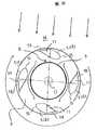
図2は図1の水平断面A-Aを示す概略図である。抗力型風車Mは、円形の天板1(図示せず)と底板3との間に、中心Oから十文字の位置毎に(90度毎の位相において)パドル5を4個配置し、天板1と底板3とは各パドル5を介して一体化されている。また、各パドル5の囲みの中の風車中心部には、円筒形の風圧ガイド7が支柱2に固定された状態で設けられている。さらに、中空状の支柱2の内部には回転可能な状態でロータ軸9が図示しない軸受で保持されている。このロータ軸9と天板1および底板3とは結合され、パドル5の回転がロータ軸9に回転伝達される。FIG. 2 is a schematic view showing a horizontal section AA of FIG. The drag type windmill M has four
図2の上方から吹いてくる風Wは、駆動側のパドル(後方から風を受けるパドル)へは風Wを集めて大きくパドルを駆動する。一方、風Wはパドル5の内周側と風圧ガイド7の隙間Sに入り込み、風の絞りで負圧となっていることが数値解析から分かった。この場合の隙間Sについては、風圧ガイド平均径が風車平均径の約0.4の場合に風車の回転効率が高くなった。その場合の隙間の大きさは、例えば風圧ガイド平均径64mm、風車平均径110mm、パドル短軸径を50mmとすると、片側28mmの隙間である。 The wind W blowing from the upper side of FIG. 2 collects the wind W to the paddle on the driving side (the paddle that receives the wind from the rear) and drives the paddle largely. On the other hand, it was found from the numerical analysis that the wind W entered the gap S between the inner peripheral side of the
本発明のパドル5は、水平断面の形状が楕円または近似楕円の約1/2である仮想半楕円形の形状をしている。風に対する抗力の風洞実験をした結果、仮想半楕円形の長軸と短軸との比が約3:1であるとパドルの抵抗、特に戻り側パドルの前凸部15の値が最も小さくなることが分かった(図3)。The
実施例1と同じ部分は同一番号で示し詳細な説明は省略する。パドル5の実施例2として後側開口部を閉じる形状17にすることで、後部の風受部に当たる風の抵抗力(駆動力)が増すことが確かめられた(図3および図4)。この後端を閉じた形状のパドル5では、その抗力型風車のいずれの方向から風が吹き込んできた場合でも、風に対して閉端面17を向ける位置のパドルで風を大きく受ける。風上に前凸部15を向ける位置のパドルでは、仮想半楕円形状の流線型で風を受ける。風を受ける抵抗は、前凸部と比べて閉端面の方が非常に大きいために、この抗力差によって一方のパドルが効率的に回進し、他方側のパドルは戻りとなってこの抗力型風車が回転する。 The same parts as those in the first embodiment are denoted by the same reference numerals, and detailed description thereof is omitted. As Example 2 of the
各パドル5は、天板1と底板3と固定ボルト33により固定されている。またパドル5の上下端の風圧セパレータ11(仕切り板)には、長孔32が2本設けられ、パドル5の位置と角度の調整が可能となっており、隙間Sの大きさやパドル5の角度(風を迎える角度)の調整を行うことができる。Each
このパドルでは、風を仮想半楕円形状の前凸部15の流線型で受けることで抵抗が極く少ないことに加え、後ろ側の閉端面17では回転に乱れを生じさせる風の渦流の発生が少ない。従来例の凹部形状(図11)では、凹部に一旦入った空気が流出する空気と衝突して乱流となるが、閉端面17では進行を妨げる渦流56の発生がほとんどない。このことからパドル5(a)の回転駆動に干渉することが少ないことから、安定した回転力を得ることができる。また風圧ガイド7とパドル内周縁との隙間Sへの風の流入によりパドル内側部に負圧が生じて風の抗力が減じ、さらに回転力が増大する。 In this paddle, the wind is received by the streamlined shape of the imaginary semi-elliptical front
実施例1と同じ部分は同一番号で示し詳細な説明は省略する。パドル5のさらに他の実施例3(図5)として、パドル外周縁端から翼19をやや風車中心部に傾けた状態で固定する。翼19とパドル5の閉端面17とは、補強リブの働きも行う風圧セパレータ11で上下および中間部が結合されている。風Wがパドル5の横方向から吹いて翼19に当たる場合(図5のW1)には、風W1の分力はパドル5の回転方向に推進力を付加する。またパドル5の後方から吹く場合(図5のW2)は、風W2は翼19と風圧セパレータ11で確実に捉えられて風を有効に利用することができる。さらに風W2は、翼19と風圧セパレータ11で捕捉されてパドル前方側へ抜ける際に発生する乱流が抑えられ、安定した回転を得ることができる。 The same parts as those in the first embodiment are denoted by the same reference numerals, and detailed description thereof is omitted. As still another
図6は、上記実施例3のパドル5と翼19、仕切り板としての風圧セパレータ11を上下端と中間部に固定したものを示す斜視図である。風圧セパレータ11は、風Wが上下左右に分散して風の力が弱くなることがないよう封じるように各パドルと翼に固定され、風の力を効率的に利用できる。また、補強リブとして機能してパドル5と翼19の剛性を高めることができる。図7はこの実施例3の平面模式図である。各パドルは風圧ガイド7の周囲を時計方向に公転する。風圧ガイド7で集められた風Wは駆動側パドル5(a)に大きく当たると共に、風圧ガイドとパドル間の隙間Sの箇所で発生する負圧により抗力が減らされて効率よく回転する。またパドルの前凸部の仮想半楕円形状で風の抗力を低減できる。また、パドルの後方を閉端面17で閉じることでさらに安定した回転力が得られる。さらにパドルに翼19、風圧セパレータ11を設けることで風の推力を有効に利用し、風車の回転力が安定して得られる。 FIG. 6 is a perspective view showing the
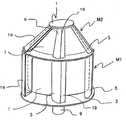
図8は、さらに他の実施例4を示したもので、実施例1と同じ部分は同一番号で示し詳細な説明は省略する。この抗力型風車Mは、小さい円形の天板1とそれより大きな底板3との間に、中心Oから十文字の位置毎に(90度毎の位相において)4個の各パドル5を配置し、天板1と底板3とが各パドル5を介して一体化されている。また、パドル5の囲みの中の中央部には、円錐形の風圧ガイド7が支柱2を介して風車Mに固定して設けられている。さらに、底板3の中心で支柱2の内部にはロータ軸9が天板1と底板3と結合され図示しない軸受により回転可能に垂設されている。各パドル5の外周端縁には翼19が設けられている。この実施例4では、翼19、パドル5、天板1の表面には太陽電池Pが貼付けられている。この太陽電池Pを設ける場合には、風車の傾斜の角度は、太陽光の入射角をより垂直方向から受けることで、太陽光発電の効率が良くなる。また太陽電池の発電効率は、表面が高温になることで発電効率が低下するが、風車の翼に張り付けることで回転冷却されて発電効率が低下することを防ぐことができる。 FIG. 8 shows still another embodiment 4. The same parts as those in the
実施例1と同じ部分は同一番号で示し詳細な説明は省略する。図9は実施例5を示す。下方に設けられた円筒形の風車M1と、上方の円錐形の風車M2を、上下2段で構成したものである。円筒形風車M1と円錐形風車M2の各ロータ軸9は結合され回転力を合成して高め、風の力を有効に利用できる。風車Mの他の特徴は上述の説明の通りであり、いずれも風圧ガイド7、仮想半楕円形状のパドル5、翼19がそれぞれの風車M1,M2に設けられている。図示はしないが、太陽電池Pは翼19やパドル5、天板1の表面に貼付され、風の無い晴れた日でも太陽光により発電が行われる。 The same parts as those in the first embodiment are denoted by the same reference numerals, and detailed description thereof is omitted. FIG. 9 shows a fifth embodiment. A cylindrical windmill M1 provided below and an upper conical windmill M2 are configured in two upper and lower stages. The
図10は、本発明の抗力型風車Mを基台23の上に搭載し、風車Mと太陽電池Pとの自然エネルギーを結合した発電装置Eを構成したものである。風車Mを地面等に固定する基台23の内部には、風力発電機25が設けられている。この発電機25は、風車Mで発生した回転を伝達するロータ軸9の回転を高める増速機27と連結されている。直交変換器29は、太陽電池Pにより発生した電気を図示しない配線を介して集められた直流電気を交流に変換する。バッテリー31は両方の電気を合わせて蓄電し、適宜、家庭や車、また電力会杜等に分配するための電気機器等が基台23の内部に設けられているFIG. 10 shows a configuration of a power generator E in which the drag type windmill M of the present invention is mounted on the
M 抗力型風車
E 発電装置
P 太陽電池
W 風
S 隙間
O 中心
1 天板
2 支柱
3 底板
5 パドル
7 風圧ガイド
9 ロータ軸
11 風圧セパレータ
13 仮想半楕円
15 前凸部
17 閉端面
19 翼
23 基台
25 風力発電機
32 長孔
33 固定ボルト
M Drag type windmill
E Power generator
P solar cell
W wind
S clearance
O center
1 Top plate
2 Prop
3 Bottom plate
5 paddle
7 Wind pressure guide
9 Rotor shaft
11 Wind pressure separator
13 Virtual half ellipse
15 Front projection
17 Closed end face
19 Wings
23 base
25 Wind generator
32 oblong holes
33 Fixing bolt
Claims (11)
Translated fromJapanesePriority Applications (1)
| Application Number | Priority Date | Filing Date | Title |
|---|---|---|---|
| JP2011242109AJP2012122477A (en) | 2010-11-15 | 2011-11-04 | Drag type windmill and wind power generation apparatus |
Applications Claiming Priority (3)
| Application Number | Priority Date | Filing Date | Title |
|---|---|---|---|
| JP2010254620 | 2010-11-15 | ||
| JP2010254620 | 2010-11-15 | ||
| JP2011242109AJP2012122477A (en) | 2010-11-15 | 2011-11-04 | Drag type windmill and wind power generation apparatus |
Publications (1)
| Publication Number | Publication Date |
|---|---|
| JP2012122477Atrue JP2012122477A (en) | 2012-06-28 |
Family
ID=46504147
Family Applications (1)
| Application Number | Title | Priority Date | Filing Date |
|---|---|---|---|
| JP2011242109APendingJP2012122477A (en) | 2010-11-15 | 2011-11-04 | Drag type windmill and wind power generation apparatus |
Country Status (1)
| Country | Link |
|---|---|
| JP (1) | JP2012122477A (en) |
Cited By (3)
| Publication number | Priority date | Publication date | Assignee | Title |
|---|---|---|---|---|
| DE102014001891A1 (en)* | 2014-02-14 | 2015-08-20 | Christian Esterhammer | Wind or hydro power plant as well as rotor |
| CN111692043A (en)* | 2020-07-22 | 2020-09-22 | 河南理工大学 | Efficient wind scoop device of resistance type vertical axis wind turbine |
| CN116181569A (en)* | 2023-03-10 | 2023-05-30 | 广西贺姚电子有限公司 | Wind-solar complementary generator |
- 2011
- 2011-11-04JPJP2011242109Apatent/JP2012122477A/enactivePending
Cited By (3)
| Publication number | Priority date | Publication date | Assignee | Title |
|---|---|---|---|---|
| DE102014001891A1 (en)* | 2014-02-14 | 2015-08-20 | Christian Esterhammer | Wind or hydro power plant as well as rotor |
| CN111692043A (en)* | 2020-07-22 | 2020-09-22 | 河南理工大学 | Efficient wind scoop device of resistance type vertical axis wind turbine |
| CN116181569A (en)* | 2023-03-10 | 2023-05-30 | 广西贺姚电子有限公司 | Wind-solar complementary generator |
Similar Documents
| Publication | Publication Date | Title |
|---|---|---|
| US10612515B2 (en) | Vertical axis wind turbine | |
| US8232664B2 (en) | Vertical axis wind turbine | |
| US7976267B2 (en) | Helix turbine system and energy production means | |
| US8257020B2 (en) | Wind turbine system for buildings | |
| US11236724B2 (en) | Vertical axis wind turbine | |
| US9041239B2 (en) | Vertical axis wind turbine with cambered airfoil blades | |
| US20110042962A1 (en) | Vertical shaft type darius windmill | |
| CN104169574B (en) | Turbine | |
| KR101236347B1 (en) | Turbine for generation of electricity by wind using construction for concentrating wind | |
| US20170335821A1 (en) | Fluid Power Generation Method and Fluid Power Generation Device | |
| KR20220084514A (en) | Vertical axis wind turbine | |
| KR20120139154A (en) | Vertical axis type wind power generator fused lift and drag | |
| US20120049536A1 (en) | Wind Turbine | |
| JP2005090332A (en) | Darrieus wind turbine | |
| KR101207023B1 (en) | A wind-power generator | |
| JP2004176551A (en) | Darrieus windmill | |
| JP4184847B2 (en) | Windmill device and wind power generator using the same | |
| JP2012122477A (en) | Drag type windmill and wind power generation apparatus | |
| KR101503358B1 (en) | Horizontal wind power generator | |
| KR20120133331A (en) | Noise reduction blade for wind power generator | |
| KR101049452B1 (en) | Wind power generation system | |
| KR20090051669A (en) | Wind-generated windmills | |
| KR20130114792A (en) | Vertical-axis wind power generator having mechanism for angle variation of wings | |
| JP2006300030A (en) | Wind turbine device and wind power generator using the same | |
| KR101363889B1 (en) | Vertical axis wind power generator |