JP2012119098A - Optical device, laser device, and extreme ultraviolet light generation apparatus - Google Patents
Optical device, laser device, and extreme ultraviolet light generation apparatusDownload PDFInfo
- Publication number
- JP2012119098A JP2012119098AJP2010265786AJP2010265786AJP2012119098AJP 2012119098 AJP2012119098 AJP 2012119098AJP 2010265786 AJP2010265786 AJP 2010265786AJP 2010265786 AJP2010265786 AJP 2010265786AJP 2012119098 AJP2012119098 AJP 2012119098A
- Authority
- JP
- Japan
- Prior art keywords
- optical device
- optical
- laser beam
- light
- laser
- Prior art date
- Legal status (The legal status is an assumption and is not a legal conclusion. Google has not performed a legal analysis and makes no representation as to the accuracy of the status listed.)
- Pending
Links
- 230000003287optical effectEffects0.000titleclaimsabstractdescription88
- 238000007493shaping processMethods0.000claimsabstractdescription50
- 239000013077target materialSubstances0.000claimsdescription23
- 239000000758substrateSubstances0.000claimsdescription13
- 239000011248coating agentSubstances0.000claimsdescription6
- 238000000576coating methodMethods0.000claimsdescription6
- 230000001678irradiating effectEffects0.000claimsdescription4
- 230000036278prepulseEffects0.000description66
- 238000012986modificationMethods0.000description16
- 230000004048modificationEffects0.000description16
- 230000003321amplificationEffects0.000description8
- 238000003199nucleic acid amplification methodMethods0.000description8
- 229910003460diamondInorganic materials0.000description4
- 239000010432diamondSubstances0.000description4
- 230000000694effectsEffects0.000description4
- 239000004065semiconductorSubstances0.000description4
- 239000007888film coatingSubstances0.000description3
- 238000009501film coatingMethods0.000description3
- 238000011084recoveryMethods0.000description3
- 238000002834transmittanceMethods0.000description3
- 238000006243chemical reactionMethods0.000description2
- 238000006073displacement reactionMethods0.000description2
- 238000000034methodMethods0.000description2
- 238000005192partitionMethods0.000description2
- 238000002310reflectometryMethods0.000description2
- 239000007787solidSubstances0.000description2
- 238000005352clarificationMethods0.000description1
- 239000000835fiberSubstances0.000description1
- 239000010419fine particleSubstances0.000description1
- 230000012447hatchingEffects0.000description1
- 239000000463materialSubstances0.000description1
- 230000000116mitigating effectEffects0.000description1
- 230000002093peripheral effectEffects0.000description1
- 238000000206photolithographyMethods0.000description1
- 230000005855radiationEffects0.000description1
- 239000013076target substanceSubstances0.000description1
- 238000011144upstream manufacturingMethods0.000description1
Images


Classifications
- F—MECHANICAL ENGINEERING; LIGHTING; HEATING; WEAPONS; BLASTING
- F21—LIGHTING
- F21V—FUNCTIONAL FEATURES OR DETAILS OF LIGHTING DEVICES OR SYSTEMS THEREOF; STRUCTURAL COMBINATIONS OF LIGHTING DEVICES WITH OTHER ARTICLES, NOT OTHERWISE PROVIDED FOR
- F21V5/00—Refractors for light sources
- F21V5/04—Refractors for light sources of lens shape
- F—MECHANICAL ENGINEERING; LIGHTING; HEATING; WEAPONS; BLASTING
- F21—LIGHTING
- F21V—FUNCTIONAL FEATURES OR DETAILS OF LIGHTING DEVICES OR SYSTEMS THEREOF; STRUCTURAL COMBINATIONS OF LIGHTING DEVICES WITH OTHER ARTICLES, NOT OTHERWISE PROVIDED FOR
- F21V11/00—Screens not covered by groups F21V1/00, F21V3/00, F21V7/00 or F21V9/00
- F21V11/02—Screens not covered by groups F21V1/00, F21V3/00, F21V7/00 or F21V9/00 using parallel laminae or strips, e.g. of Venetian-blind type
- F—MECHANICAL ENGINEERING; LIGHTING; HEATING; WEAPONS; BLASTING
- F21—LIGHTING
- F21V—FUNCTIONAL FEATURES OR DETAILS OF LIGHTING DEVICES OR SYSTEMS THEREOF; STRUCTURAL COMBINATIONS OF LIGHTING DEVICES WITH OTHER ARTICLES, NOT OTHERWISE PROVIDED FOR
- F21V7/00—Reflectors for light sources
- F—MECHANICAL ENGINEERING; LIGHTING; HEATING; WEAPONS; BLASTING
- F21—LIGHTING
- F21V—FUNCTIONAL FEATURES OR DETAILS OF LIGHTING DEVICES OR SYSTEMS THEREOF; STRUCTURAL COMBINATIONS OF LIGHTING DEVICES WITH OTHER ARTICLES, NOT OTHERWISE PROVIDED FOR
- F21V7/00—Reflectors for light sources
- F21V7/04—Optical design
- F21V7/06—Optical design with parabolic curvature
- G—PHYSICS
- G01—MEASURING; TESTING
- G01N—INVESTIGATING OR ANALYSING MATERIALS BY DETERMINING THEIR CHEMICAL OR PHYSICAL PROPERTIES
- G01N21/00—Investigating or analysing materials by the use of optical means, i.e. using sub-millimetre waves, infrared, visible or ultraviolet light
- G01N21/17—Systems in which incident light is modified in accordance with the properties of the material investigated
- G01N21/55—Specular reflectivity
- G—PHYSICS
- G02—OPTICS
- G02B—OPTICAL ELEMENTS, SYSTEMS OR APPARATUS
- G02B19/00—Condensers, e.g. light collectors or similar non-imaging optics
- G02B19/0004—Condensers, e.g. light collectors or similar non-imaging optics characterised by the optical means employed
- G02B19/0028—Condensers, e.g. light collectors or similar non-imaging optics characterised by the optical means employed refractive and reflective surfaces, e.g. non-imaging catadioptric systems
- G—PHYSICS
- G02—OPTICS
- G02B—OPTICAL ELEMENTS, SYSTEMS OR APPARATUS
- G02B19/00—Condensers, e.g. light collectors or similar non-imaging optics
- G02B19/0033—Condensers, e.g. light collectors or similar non-imaging optics characterised by the use
- G02B19/0047—Condensers, e.g. light collectors or similar non-imaging optics characterised by the use for use with a light source
- G02B19/0052—Condensers, e.g. light collectors or similar non-imaging optics characterised by the use for use with a light source the light source comprising a laser diode
- G—PHYSICS
- G02—OPTICS
- G02B—OPTICAL ELEMENTS, SYSTEMS OR APPARATUS
- G02B19/00—Condensers, e.g. light collectors or similar non-imaging optics
- G02B19/0033—Condensers, e.g. light collectors or similar non-imaging optics characterised by the use
- G02B19/0095—Condensers, e.g. light collectors or similar non-imaging optics characterised by the use for use with ultraviolet radiation
- G—PHYSICS
- G02—OPTICS
- G02B—OPTICAL ELEMENTS, SYSTEMS OR APPARATUS
- G02B27/00—Optical systems or apparatus not provided for by any of the groups G02B1/00 - G02B26/00, G02B30/00
- G02B27/09—Beam shaping, e.g. changing the cross-sectional area, not otherwise provided for
- G02B27/0927—Systems for changing the beam intensity distribution, e.g. Gaussian to top-hat
- G—PHYSICS
- G02—OPTICS
- G02B—OPTICAL ELEMENTS, SYSTEMS OR APPARATUS
- G02B27/00—Optical systems or apparatus not provided for by any of the groups G02B1/00 - G02B26/00, G02B30/00
- G02B27/09—Beam shaping, e.g. changing the cross-sectional area, not otherwise provided for
- G02B27/0938—Using specific optical elements
- G02B27/095—Refractive optical elements
- G02B27/0955—Lenses
- G—PHYSICS
- G02—OPTICS
- G02B—OPTICAL ELEMENTS, SYSTEMS OR APPARATUS
- G02B5/00—Optical elements other than lenses
- G02B5/001—Axicons, waxicons, reflaxicons
- H—ELECTRICITY
- H05—ELECTRIC TECHNIQUES NOT OTHERWISE PROVIDED FOR
- H05G—X-RAY TECHNIQUE
- H05G2/00—Apparatus or processes specially adapted for producing X-rays, not involving X-ray tubes, e.g. involving generation of a plasma
- H05G2/001—Production of X-ray radiation generated from plasma
- H05G2/008—Production of X-ray radiation generated from plasma involving an energy-carrying beam in the process of plasma generation
- H05G2/0082—Production of X-ray radiation generated from plasma involving an energy-carrying beam in the process of plasma generation the energy-carrying beam being a laser beam
- H05G2/0086—Optical arrangements for conveying the laser beam to the plasma generation location
- H—ELECTRICITY
- H01—ELECTRIC ELEMENTS
- H01S—DEVICES USING THE PROCESS OF LIGHT AMPLIFICATION BY STIMULATED EMISSION OF RADIATION [LASER] TO AMPLIFY OR GENERATE LIGHT; DEVICES USING STIMULATED EMISSION OF ELECTROMAGNETIC RADIATION IN WAVE RANGES OTHER THAN OPTICAL
- H01S3/00—Lasers, i.e. devices using stimulated emission of electromagnetic radiation in the infrared, visible or ultraviolet wave range
- H01S3/005—Optical devices external to the laser cavity, specially adapted for lasers, e.g. for homogenisation of the beam or for manipulating laser pulses, e.g. pulse shaping
- H01S3/0071—Beam steering, e.g. whereby a mirror outside the cavity is present to change the beam direction
- H—ELECTRICITY
- H01—ELECTRIC ELEMENTS
- H01S—DEVICES USING THE PROCESS OF LIGHT AMPLIFICATION BY STIMULATED EMISSION OF RADIATION [LASER] TO AMPLIFY OR GENERATE LIGHT; DEVICES USING STIMULATED EMISSION OF ELECTROMAGNETIC RADIATION IN WAVE RANGES OTHER THAN OPTICAL
- H01S3/00—Lasers, i.e. devices using stimulated emission of electromagnetic radiation in the infrared, visible or ultraviolet wave range
- H01S3/14—Lasers, i.e. devices using stimulated emission of electromagnetic radiation in the infrared, visible or ultraviolet wave range characterised by the material used as the active medium
- H01S3/22—Gases
- H01S3/223—Gases the active gas being polyatomic, i.e. containing two or more atoms
- H01S3/2232—Carbon dioxide (CO2) or monoxide [CO]
- H—ELECTRICITY
- H01—ELECTRIC ELEMENTS
- H01S—DEVICES USING THE PROCESS OF LIGHT AMPLIFICATION BY STIMULATED EMISSION OF RADIATION [LASER] TO AMPLIFY OR GENERATE LIGHT; DEVICES USING STIMULATED EMISSION OF ELECTROMAGNETIC RADIATION IN WAVE RANGES OTHER THAN OPTICAL
- H01S3/00—Lasers, i.e. devices using stimulated emission of electromagnetic radiation in the infrared, visible or ultraviolet wave range
- H01S3/23—Arrangements of two or more lasers not provided for in groups H01S3/02 - H01S3/22, e.g. tandem arrangements of separate active media
- H01S3/2308—Amplifier arrangements, e.g. MOPA
- H01S3/2316—Cascaded amplifiers
Landscapes
- Physics & Mathematics (AREA)
- Optics & Photonics (AREA)
- General Physics & Mathematics (AREA)
- Engineering & Computer Science (AREA)
- General Engineering & Computer Science (AREA)
- Plasma & Fusion (AREA)
- Analytical Chemistry (AREA)
- Chemical & Material Sciences (AREA)
- Life Sciences & Earth Sciences (AREA)
- Biochemistry (AREA)
- General Health & Medical Sciences (AREA)
- Immunology (AREA)
- Pathology (AREA)
- Health & Medical Sciences (AREA)
- Exposure And Positioning Against Photoresist Photosensitive Materials (AREA)
- X-Ray Techniques (AREA)
- Exposure Of Semiconductors, Excluding Electron Or Ion Beam Exposure (AREA)
- Lenses (AREA)
- Lasers (AREA)
Abstract
Translated fromJapaneseDescription
Translated fromJapanese本開示は、光学装置、レーザ装置および極端紫外光生成装置に関する。 The present disclosure relates to an optical device, a laser device, and an extreme ultraviolet light generation device.
たとえば半導体プロセスのフォトリソグラフィに使用する光源装置としては、エキシマレーザが存在する。また、近年では、半導体プロセスのさらなる微細化を目的として、極端紫外(Extreme Ultraviolet:EUV)光生成装置の研究が進められている。これらの光生成装置は、レーザ加工装置にも使用される場合がある。 For example, an excimer laser exists as a light source device used for photolithography in a semiconductor process. In recent years, extreme ultraviolet (EUV) light generation apparatuses have been studied for the purpose of further miniaturization of semiconductor processes. These light generation apparatuses may also be used for laser processing apparatuses.
EUV光生成装置には、LPP(Laser−Produced Plasma)方式装置やDPP(Discharge Produced Plasma)方式装置やSR(Synchrotron Radiation)方式装置などが存在する。LPP方式のEUV光生成装置には、ターゲット物質に対してメインパルスレーザ光を照射する前にプレパルスレーザ光を照射する、いわゆる多段レーザ光照射タイプが存在する。 EUV light generation apparatuses include LPP (Laser-Producted Plasma) system apparatuses, DPP (Discharge Produced Plasma) system apparatuses, SR (Synchrontron Radiation) system apparatuses, and the like. There is a so-called multi-stage laser light irradiation type in which pre-pulse laser light is irradiated before irradiating a target material with main pulse laser light in an LPP type EUV light generation apparatus.
本開示の一態様による光学装置は、入射する第1のレーザ光をビーム断面が円環状の第2のレーザ光に変換する第1のビーム整形部と、前記第2のレーザ光を第1の所定の位置に集光して、ベッセルビームを形成させる第1の集光光学素子と、を備えてもよい。 An optical device according to an aspect of the present disclosure includes a first beam shaping unit that converts incident first laser light into second laser light having an annular beam cross section, and the second laser light as a first laser light. A first condensing optical element that condenses light at a predetermined position to form a Bessel beam.
また、本開示の他の形態によるレーザ装置は、上述の光学装置と、少なくとも1つのレーザ生成システムと、を備えてもよい。 A laser device according to another embodiment of the present disclosure may include the above-described optical device and at least one laser generation system.
また、本開示の他の態様による極端紫外光生成装置は、上述の光学装置と、少なくとも1つのレーザ生成システムを含むレーザ装置と、前記レーザ装置から出力されるレーザ光が入射するための少なくとも1つの入射口が設けられたチャンバと、前記チャンバ内で、前記レーザ光が照射されるターゲット物質を前記チャンバ内に供給するターゲット供給部と、前記レーザ光が前記ターゲット物質に照射されることによって生成される光のうち、所定の波長の光を選択的に反射する、集光ミラーと、を備えてもよい。 Further, an extreme ultraviolet light generation device according to another aspect of the present disclosure includes at least one of the above-described optical device, a laser device including at least one laser generation system, and laser light output from the laser device. Generated by irradiating the target material with the laser beam, a target supply unit for supplying the target material to be irradiated with the laser light into the chamber, A light collecting mirror that selectively reflects light having a predetermined wavelength among the light to be emitted.
以下、本開示を実施するための形態を図面を参照に詳細に説明する。なお、以下の説明において、各図は本開示の内容を理解でき得る程度に形状、大きさ、および位置関係を概略的に示してあるに過ぎず、従って、本開示は各図で例示された形状、大きさ、および位置関係のみに限定されるものではない。また、各図では、構成の明瞭化のため、断面におけるハッチングの一部が省略されている。さらに、後述において例示する数値は、本開示の好適な例に過ぎず、従って、本開示は例示された数値に限定されるものではない。 Hereinafter, embodiments for carrying out the present disclosure will be described in detail with reference to the drawings. In the following description, each drawing merely schematically shows the shape, size, and positional relationship to the extent that the contents of the present disclosure can be understood. Therefore, the present disclosure is illustrated in each drawing. It is not limited to only the shape, size, and positional relationship. Moreover, in each figure, a part of hatching in a cross section is abbreviate | omitted for clarification of a structure. Furthermore, the numerical values exemplified below are only suitable examples of the present disclosure, and therefore the present disclosure is not limited to the illustrated numerical values.
なお、本明細書においては、光軸は光学系において系全体を通過する光束の代表となる仮想的な光線と定義する。具体的には集光レンズ、集光ミラー、アキシコンレンズ及びアキシコンミラー等の光軸は回転対称軸と一致する。 In this specification, the optical axis is defined as a virtual light beam that is representative of a light beam that passes through the entire system in the optical system. Specifically, the optical axes of the condenser lens, condenser mirror, axicon lens, axicon mirror, and the like coincide with the rotational symmetry axis.
(実施の形態1)
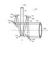
以下、本開示の実施の形態1について、図面を参照して詳細に説明する。図1は、実施の形態1によるEUV光生成装置の概略構成を示す。EUV光生成装置100は、ドライバレーザ101と、プリパルスレーザ102と、チャンバ40とを備えることができる。(Embodiment 1)
Hereinafter,
/ドライバレーザ
ドライバレーザ101は、マスタオシレータMOと、リレー光学系R1〜R3と、プリアンプPAと、メインアンプMAと、高反射ミラーM3とを備えてもよい。/ Driver Laser The
マスタオシレータMOは、パルス状のレーザ光をシード光L1として出力する。このマスタオシレータMOには、たとえば量子カスケードレーザや分布帰還型半導体レーザなどの半導体レーザを用いてもよい。ただし、これらに限定されず、固体レーザ、ガスレーザなどの種々のレーザを用いてもよい。 The master oscillator MO outputs pulsed laser light as seed light L1. For the master oscillator MO, for example, a semiconductor laser such as a quantum cascade laser or a distributed feedback semiconductor laser may be used. However, the present invention is not limited to these, and various lasers such as a solid laser and a gas laser may be used.
マスタオシレータMOから出力されたシード光L1は、リレー光学系R1によってそのビーム径が拡大された後、プリアンプPAに入射する。プリアンプPAは、たとえばCO2ガスを主たる増幅媒体としたガス増幅器でよい。リレー光学系R1は、シード光L1がプリアンプPAの増幅領域で効率的に増幅されるように、シード光L1のビーム径を拡大する。プリアンプPAは、入射したシード光L1のうち、増幅媒体に特有の少なくとも1つの増幅波長帯域に含まれる波長のレーザ光を増幅して、メインパルスレーザ光L2として出力する。The seed light L1 output from the master oscillator MO is incident on the preamplifier PA after its beam diameter is expanded by the relay optical system R1. The preamplifier PA may be a gas amplifier using, for example, CO2 gas as a main amplification medium. The relay optical system R1 expands the beam diameter of the seed light L1 so that the seed light L1 is efficiently amplified in the amplification region of the preamplifier PA. The preamplifier PA amplifies laser light having a wavelength included in at least one amplification wavelength band specific to the amplification medium in the incident seed light L1, and outputs the amplified laser light as main pulse laser light L2.
プリアンプPAから出力されたレーザ光L2は、リレー光学系R2でそのビーム径が拡大されつつ平行光化された後、メインアンプMAに入射する。メインアンプMAは、プリアンプPAと同様、たとえばCO2ガスを主たる増幅媒体としたガス増幅器でよい。リレー光学系R2は、メインパルスレーザ光L2がメインアンプMAの増幅領域で効率的に増幅されるように、メインパルスレーザ光L2のビーム径を拡大する。メインアンプMAは、プリアンプPAと同様、入射したレーザ光L2のうち、増幅媒体に特有の少なくとも1つの増幅波長帯域に含まれる波長のレーザ光を増幅する。The laser beam L2 output from the preamplifier PA is collimated while its beam diameter is enlarged by the relay optical system R2, and then enters the main amplifier MA. As with the preamplifier PA, the main amplifier MA may be a gas amplifier using, for example, CO2 gas as a main amplification medium. The relay optical system R2 expands the beam diameter of the main pulse laser beam L2 so that the main pulse laser beam L2 is efficiently amplified in the amplification region of the main amplifier MA. As with the preamplifier PA, the main amplifier MA amplifies laser light having a wavelength included in at least one amplification wavelength band unique to the amplification medium in the incident laser light L2.
メインアンプMAから出力されたメインパルスレーザ光L2は、リレー光学系R3で平行光化された後、高反射ミラーM3で反射されて、ドライバレーザ101から出力される。なお、リレー光学系R3および高反射ミラーM3は、ドライバレーザ101に含まれなくてもよい。 The main pulse laser beam L2 output from the main amplifier MA is collimated by the relay optical system R3, reflected by the high reflection mirror M3, and output from the
/プリパルスレーザ
一方、プリパルスレーザ102は、プリパルスレーザ光源PLと、リレー光学系R4とを備えてもよい。プリパルスレーザ光源PLは、チャンバ40内に供給されるターゲット物質(ドロップレットD)に照射されるパルス状のレーザ光をプリパルスレーザ光L3として出力する。このプリパルスレーザ光源PLには固体レーザ、ガスレーザまたはファイバレーザなど、種々のレーザを用いてよい。プリパルスレーザ光源PLから出力されたプリパルスレーザ光L3は、リレー光学系R4にてそのビーム径が拡大された後、プリパルスレーザ102から出力される。/ Prepulse Laser On the other hand, the
/チャンバ
ドライバレーザ101から出力されたメインパルスレーザ光L2は、ウィンドウW1を介してチャンバ40内に入射する。プリパルスレーザ102から出力されたプリパルスレーザ光L3は、ウィンドウW2を介してチャンバ40内に入射する。チャンバ40には、レーザ光の集光光学系として、ビーム整形部20と、凹面アキシコンミラー30と、集光レンズ31と、が配置されてもよい。また、チャンバ40には、ドロップレットジェネレータ41と、ドロップレット回収部43と、電磁石コイル44と、EUV集光ミラー45と、が配置されてもよい。/ The main pulse laser beam L2 outputted from the
//ウィンドウ
ウィンドウW1およびW2は、たとえばダイヤモンド基板など、メインパルスレーザ光L2またはプリパルスレーザ光L3に対する透過率が高く、且つ熱安定性に優れた透明基板であるのが好ましい。また、ウィンドウW1およびW2は、表面で反射される光がたとえばリレー光学系R3およびR4などの上流の光学系における光学素子表面でホットスポットを形成しないように、レーザ光の中心軸に対して3〜5°程度傾いて配置されることが好ましい。// Window It is preferable that the windows W1 and W2 are transparent substrates having high transmittance with respect to the main pulse laser beam L2 or the prepulse laser beam L3 and excellent in thermal stability, such as a diamond substrate. Further, the windows W1 and W2 are 3 with respect to the central axis of the laser beam so that the light reflected on the surface does not form a hot spot on the surface of the optical element in the upstream optical system such as the relay optical systems R3 and R4. It is preferable to be disposed at an angle of about ~ 5 °.
//ビーム整形部
ウィンドウW1からチャンバ40内に入射したメインパルスレーザ光L2は、ビーム整形部20によってビーム断面が円環状の円筒メインパルスレーザ光L2aに変換される。ここで、図2および図3に、本実施の形態1によるビーム整形部の一例を示す。なお、図3は、図2に示すビーム整形部の、レーザ光の中心軸AX2を含む面における断面を示す。図2に示すように、ビーム整形部20は、2つの円錐状のアキシコンレンズ21および22を備えてもよい。図3に示すように、2つのアキシコンレンズ21および22は、互いにその頂点が向かい合うように配置されるのが好ましい。アキシコンレンズ21および22は、それぞれの光軸(回転軸)が実質的に同一直線上に位置するように配置されるのが好ましい。このように構成されるビーム整形部20に対し、一方のアキシコンレンズ21の底面にたとえばビーム断面が円形のメインパルスレーザ光L2が入射すると、他方のアキシコンレンズ22の底面からは、ビーム断面が円環状の円筒メインパルスレーザ光L2aが出射する。この構成において、2つのアキシコンレンズ21および22の頂点間の距離を調節することで、円筒メインパルスレーザ光L2aのビーム断面の径を調節することができる。なお、メインパルスレーザ光L2は、アキシコンレンズ21および22の底面それぞれに対して実質的に垂直に入射するのが好ましい。そして、この両アキシコンレンズの表面に反射防止膜をコートすることが好ましい。// Beam shaping unit The main pulse laser beam L2 incident in the
//凹面アキシコンミラー
円筒メインパルスレーザ光L2aは、たとえば高反射ミラーM22で反射された後、集光光学系における凹面アキシコンミラー30に入射する。図4に、凹面アキシコンミラーの一例を示す。図5に、図4の凹面アキシコンミラーで反射されたレーザ光を示す。図4に示すように、凹面アキシコンミラー30は、内部に円錐台状の空洞を備えた円筒状の部材でよい。凹面アキシコンミラー30の内周は、下底30aの径が、上底30bの径よりも大きい。ビーム整形部20で整形された円筒メインパルスレーザ光L2aは、下底30a側から入射する。この円筒メインパルスレーザ光L2aが凹面アキシコンミラー30の内側面で反射されると、円筒メインパルスレーザ光L2aは平行光のまま絞り込まれるように集束する。円筒メインパルスレーザ光L2aを集束させることにより、図5に示すように円筒メインパルスレーザ光L2aが集束する部分に、所謂ベッセルビームVL2が形成される。この際、入射する円筒メインパルスレーザ光L2aの中心軸は、凹面アキシコンミラー30の光軸AXmと実質的に一致しているのが好ましい。それにより、ベッセルビームVL2は、円筒メインパルスレーザ光L2aの中心軸上に形成され得る。ベッセルビームVL2を形成することで、メインパルスレーザ光L2の実質的な焦点深度を深くすることが可能となり、レーザ光の中心軸方向におけるターゲット物質の変位による照射精度への影響を低減することが可能となる。本実施の形態1では、円筒メインパルスレーザ光L2aが集束する領域を、プラズマ生成サイトP1またはその付近に設定する。これにより、より確実にメインパルスレーザ光L2をターゲット物質(たとえばドロップレットD、または、ドロップレットDが変容した膨張ターゲットDD)に照射することが可能となると推測される。// Concave Axicon Mirror The cylindrical main pulse laser light L2a is reflected by, for example, the high reflection mirror M22 and then enters the
一方、プリパルスレーザ102から出力されたプリパルスレーザ光L3(図1参照)は、たとえば高反射ミラーM4で反射された後、ウィンドウW2を介してチャンバ40内に入射する。チャンバ40内に入射したプリパルスレーザ光L3は、たとえば高反射ミラーM21で反射される。高反射ミラーM21は、たとえば円筒メインパルスレーザ光L2aの光路上で円筒メインパルスレーザ光L2aの中空部分に配置されてもよい。具体的には、高反射ミラー21は、たとえばビーム整形部20と高反射ミラー22の間に、円筒メインパルスレーザ光L2aを遮らないように配置され得る。プリパルスレーザ光L3は、高反射ミラーM21で反射された後、円筒メインパルスレーザ光L2aと同様に、高反射ミラーM22で反射される。高反射ミラーM22で反射されたプリパルスレーザ光L3は、集光レンズ31(図1参照)に入射する。 On the other hand, the prepulse laser beam L3 (see FIG. 1) output from the
//集光レンズ
集光レンズ31は、たとえば円筒メインパルスレーザ光L2aの光路上で円筒メインパルスレーザ光L2aの中空部分に配置される。集光レンズ31の径は、凹面アキシコンミラー30の内径よりも小さいのが好ましい。集光レンズ31は、その光軸が凹面アキシコンミラー30の光軸AXmと実質的に一致するように配置されるのが好ましい。集光レンズ31は、入射したプリパルスレーザ光L3をプラズマ生成サイトP1またはその付近に集光する。プリパルスレーザ光L3は、凹面アキシコンミラー30の空洞を通過してプラズマ生成サイトP1またはその付近に集光される。すなわち、プリパルスレーザ光L3は、メインパルスレーザ光L2と同一方向(EUV集光ミラー45側)からプラズマ生成サイトP1付近に集光される。なお、メインパルスレーザ光L2の集光点とプリパルスレーザ光L3の集光点とは、一致していても、一致していなくてもよい。// Condensing lens The condensing
//ドロップレットジェネレータ
再び図1を参照に、プラズマ生成サイトP1またはその付近には、プラズマの生成材料となるターゲット物質(たとえばSn)がドロップレットジェネレータ41から供給される。ドロップレットジェネレータ41は、たとえばダーゲット物質をドロップレットDの形態で供給する。具体的には、ドロップレットジェネレータ41は、ターゲット物質であるSnを融解した状態で貯留し、これをノズル41aを介してドロップレットDの状態でプラズマ生成サイトP1へ向けて出力する。// Droplet generator Referring to FIG. 1 again, a target substance (for example, Sn) serving as a plasma generation material is supplied from the
“膨張ターゲット(プリプラズマと飛散ターゲット)”
プラズマ生成サイトP1に到着したドロップレットDには、プリパルスレーザ光L3が照射される。このプリパルスレーザ光L3の照射によって、ドロップレットDが膨張ターゲットDDに変容する。なお、本説明において、膨張ターゲットDDとは、プリプラズマと飛散ターゲットの少なくとも一方を含む状態のターゲットとする。プリプラズマとは、たとえばプラズマ状態またはプラズマと気体状態の原子との混合状態である。また、飛散ターゲットとは、レーザ光の照射によりターゲット物質が分裂して変容したクラスタ、マイクロドロップレット等の微粒子、または、それらが混在する微粒子群であり得る。“Expansion target (pre-plasma and scattering target)”
The droplet D arriving at the plasma generation site P1 is irradiated with the pre-pulse laser beam L3. By the irradiation with the pre-pulse laser beam L3, the droplet D is transformed into the expansion target DD. In the present description, the expansion target DD is a target including at least one of pre-plasma and a scattering target. Pre-plasma is, for example, a plasma state or a mixed state of plasma and gaseous atoms. Further, the scattering target may be a cluster such as a cluster, microdroplet, or the like in which a target material is split and transformed by laser light irradiation, or a group of fine particles in which they are mixed.
また、膨張ターゲットDDには、メインパルスレーザ光L2(ベッセルビームVL2)が照射される。これにより、膨張ターゲットDDからプラズマが生成される。このプラズマからは、所定の波長(たとえば13.5nm)のEUV光L4を含む光が放出される。この放出された光の一部は、EUV集光ミラー45に入射する。 The expansion target DD is irradiated with the main pulse laser beam L2 (Bessel beam VL2). Thereby, plasma is generated from the expansion target DD. From this plasma, light including EUV light L4 having a predetermined wavelength (for example, 13.5 nm) is emitted. A part of the emitted light is incident on the
//EUV集光ミラー
EUV集光ミラー45は、入射した光のうち、所定の波長のEUV光L4を選択的に反射する。また、EUV集光ミラー45は、選択的に反射したEUV光L4を所定の位置(たとえば中間集光点IF)に集光させる。 なお、EUV集光ミラー45には、反射面中央部に軸方向に設けられた貫通孔45aが形成されていてもよい。プリパルスレーザ光L3およびメインパルスレーザ光L2は、たとえば貫通孔45aを介してプラズマ生成サイトP1またはその付近に集光される。これにより、プリパルスレーザ光L3およびメインパルスレーザ光L2を、EUV集光ミラー45の背面側からプラズマ生成サイトP1またはその付近に集光させることが可能となる。// EUV collector mirror The
//露光装置接続部と露光装置
中間集光点IFは、たとえばチャンバ40と露光装置60とを接続する露光装置接続部50内に設定されてもよい。また、露光装置接続部50には、ピンホールをもつ隔壁51が設けられてもよい。中間集光点IFに集光されたEUV光L4は、隔壁51のピンホールを通過した後、不図示の光学系を介して露光装置60へ導入される。// Exposure apparatus connection unit and exposure apparatus The intermediate focusing point IF may be set in an exposure
//ドロップレット回収部
また、プラズマ生成サイトP1付近に到着したドロップレットDのうち、プリパルスレーザ光L3やメインパルスレーザ光L2が照射されなかったドロップレットDや、プラズマの生成に寄与しなかった残りのターゲット物質は、たとえばドロップレット回収部43に回収されるとよい。// Droplet recovery unit Of the droplets D arriving near the plasma generation site P1, the droplets D that were not irradiated with the pre-pulse laser beam L3 and the main pulse laser beam L2 did not contribute to the generation of plasma. The remaining target material may be recovered by the
//磁場ミチゲーション(電磁石コイル)
また、プラズマ生成サイトP1付近には、プラズマ生成の際に発生したデブリをトラップするための局所磁場が生成されてもよい。この局所磁場は、たとえば電磁石コイル44を用いて生成することができる。なお、局所磁場の方向は、ドロップレットDの進行方向と異なる方向であってもよい。また、局所磁場方向におけるプラズマ生成サイトP1を挟む2つの位置には、それぞれデブリ回収部(不図示)を設けることができる。局所磁場にトラップされたデブリは、磁力線にラーマー(サイクロトロン)運動しつつ局所磁場方向に移動することで、デブリ回収部に回収される。// Magnetic field mitigation (electromagnetic coil)
Further, a local magnetic field for trapping debris generated during plasma generation may be generated near the plasma generation site P1. This local magnetic field can be generated using, for example, the
本実施の形態1によれば、プラズマ生成サイトP1またはその付近にメインパルスレーザ光L2のベッセルビームVL2を形成するため、メインパルスレーザ光L2の焦点深度を深くすることが可能となる。それにより、レーザ光の中心軸方向におけるターゲット物質の変位による照射精度への影響を低減し、より確実にメインパルスレーザ光L2をターゲット物質(たとえばドロップレットD、もしくは、ドロップレットDが変容した膨張ターゲットDD)に照射することが可能となると推測される。さらに、焦点深度を深くすることで、集光光学系を移動させてメインパルスレーザ光L2の焦点を調整する必要性が低減され得る。 According to the first embodiment, since the Bessel beam VL2 of the main pulse laser beam L2 is formed at or near the plasma generation site P1, the depth of focus of the main pulse laser beam L2 can be increased. Thereby, the influence on the irradiation accuracy due to the displacement of the target material in the central axis direction of the laser beam is reduced, and the expansion of the main pulse laser beam L2 is more reliably transformed into the target material (for example, the droplet D or the droplet D). It is assumed that the target DD) can be irradiated. Furthermore, by increasing the depth of focus, the necessity to adjust the focus of the main pulse laser beam L2 by moving the condensing optical system can be reduced.
また、本実施の形態1のように、メインパルスレーザ光L2をビーム断面が円環状の円筒メインパルスレーザ光L2aに変換することで、ダイクロイックミラーなどの合波光学素子を用いずに、プリパルスレーザ光L3とメインパルスレーザ光L2とを実質的に同一方向からターゲット物質に照射することが可能となる。これにより、合波光学素子などによるエネルギーロスを低減できる。プリパルスレーザ光L3とメインパルスレーザ光L2とを実質的に同一方向からターゲット物質に照射することで、ターゲット物質を効率的にプラズマ化することが可能となる。この結果、EUV光L4へのエネルギー変換効率(Conversion Efficiency:CE)が改善し、高出力のEUV光L4を得ることができる場合がある。 Further, as in the first embodiment, the main pulse laser beam L2 is converted into a cylindrical main pulse laser beam L2a having an annular beam cross section, so that a prepulse laser can be used without using a multiplexing optical element such as a dichroic mirror. The target material can be irradiated with the light L3 and the main pulse laser beam L2 from substantially the same direction. Thereby, the energy loss by a multiplexing optical element etc. can be reduced. By irradiating the target material with the pre-pulse laser beam L3 and the main pulse laser beam L2 from substantially the same direction, the target material can be efficiently converted into plasma. As a result, energy conversion efficiency (Conversion Efficiency: CE) to EUV light L4 may be improved, and high-power EUV light L4 may be obtained.
(実施の形態2)
つぎに、本開示の実施の形態2について、図面を参照して詳細に説明する。以下の説明において、実施の形態1と同様の構成については、同一の符号を付し、その重複する説明を省略する。(Embodiment 2)
Next, a second embodiment of the present disclosure will be described in detail with reference to the drawings. In the following description, the same components as those in the first embodiment are denoted by the same reference numerals, and redundant description thereof is omitted.
図6は、実施の形態2によるEUV光生成装置の概略構成を示す。図1と図6とを比較すると明らかなように、EUV光生成装置200(図6)は、EUV光生成装置100(図1)と同様の構成を備える。ただし、EUV光生成装置200は、プラズマ生成サイトP1付近でプリパルスレーザ光L3のベッセルビームVL3を形成する。そこで、EUV光生成装置200は、プリパルスレーザ光L3を円筒状の円筒プリパルスレーザ光L3aに変換するビーム整形部220を備えるとともに、EUV光生成装置100における集光レンズ31が円筒プリパルスレーザ光L3aをプラズマ生成サイトP1付近に平行光のまま集束させるアキシコンレンズ231に置き換えられる。 FIG. 6 shows a schematic configuration of the EUV light generation apparatus according to the second embodiment. As is clear from comparison between FIG. 1 and FIG. 6, the EUV light generation apparatus 200 (FIG. 6) has the same configuration as the EUV light generation apparatus 100 (FIG. 1). However, the EUV
//プリパルスレーザ光用ビーム整形部
ビーム整形部220は、たとえば図2および図3に示すビーム整形部20と同様である。このビーム整形部220によって変換された円筒プリパルスレーザ光L3aは、高反射ミラーM21およびM22で反射された後、アキシコンレンズ231に入射する。// Beam shaping unit for prepulse laser light The
//アキシコンレンズ
図7に、アキシコンレンズの一例を示す。円筒プリパルスレーザ光L3aは、アキシコンレンズ231の底面に入射する。円筒プリパルスレーザ光L3aは、円筒プリパルスレーザ光L3aの中心軸とアキシコンレンズ231の回転軸とが実質的に一致するようにアキシコンレンズ231に入射するのが好ましい。この円筒プリパルスレーザ光L3aがアキシコンレンズ231の斜面から出射すると、円筒プリパルスレーザ光L3aは平行光のまま絞り込まれるように集束する。円筒プリパルスレーザ光L3aを集束させることにより、図8に示すように、円筒プリパルスレーザ光L3aが集束する部分に所謂ベッセルビームVL3が形成される。ベッセルビームVL3は、円筒プリパルスレーザ光L3aの中心軸に形成される。このようにベッセルビームVL3を形成することで、プリパルスレーザ光L3の実質的な焦点深度を深くすることが可能となる。本実施の形態2では、円筒プリパルスレーザ光L3aが集束する領域を、プラズマ生成サイトP1付近に設定する。これにより、より確実にプリパルスレーザ光L3をターゲット物質(たとえばドロップレットD)に照射することが可能となる。なお、ベッセルビームVL3が形成される領域とベッセルビームVL2が形成される領域とが少なくとも部分的に重なるよう、集光光学系などを配置してもよい。// Axicon Lens FIG. 7 shows an example of an axicon lens. The cylindrical prepulse laser beam L3a is incident on the bottom surface of the
この他の構成、動作および効果は、実施の形態1と同様であるため、ここでは詳細な説明を省略する。 Since other configurations, operations, and effects are the same as those in the first embodiment, detailed description thereof is omitted here.
(実施の形態3)
つぎに、本開示の実施の形態3について、図面を参照して詳細に説明する。以下の説明において、実施の形態1または2と同様の構成については、同一の符号を付し、その重複する説明を省略する。(Embodiment 3)
Next, a third embodiment of the present disclosure will be described in detail with reference to the drawings. In the following description, the same reference numerals are given to the same configurations as those in the first or second embodiment, and the overlapping description is omitted.
図9は、実施の形態3によるEUV光生成装置の概略構成を示す。図6と図9とを比較すると明らかなように、EUV光生成装置300(図9)は、EUV光生成装置200(図6)と同様の構成を備える。ただし、EUV光生成装置300では、EUV光生成装置200におけるアキシコンミラー231が、同心円状の複数のトレンチまたはリッジが形成された回折格子331に置き換えられる。 FIG. 9 shows a schematic configuration of an EUV light generation apparatus according to the third embodiment. As is clear from comparison between FIG. 6 and FIG. 9, the EUV light generation apparatus 300 (FIG. 9) has the same configuration as the EUV light generation apparatus 200 (FIG. 6). However, in the EUV
//回折格子
図10に、回折格子の一例を示す。図10に示すように、回折格子331は、円盤状の透明基板331aの一方の主平面に、同心円状に形成された複数のトレンチまたはリッジが形成された回折部331bを含む。透明基板331aは、たとえばダイヤモンド基板などでよい。回折部331bの径は、円筒プリパルスレーザ光L3aの径と一致するのが好ましい。回折格子331は、その光軸が凹面アキシコンミラー30の光軸AXmと実質的に一致するように配置されるのが好ましい。// Diffraction grating FIG. 10 shows an example of a diffraction grating. As shown in FIG. 10, the
円筒プリパルスレーザ光L3aは、透明基板331aの他方の主平面に略垂直に入射する。この円筒プリパルスレーザ光L3aが回折格子331の回折部331bから出射されると、図11に示すように、円筒プリパルスレーザ光L3aの回折光L3cがプラズマ生成サイトP1付近に集光される。この結果、プラズマ生成サイトP1またはその付近に、円筒プリパルスレーザ光L3aの中心軸上に所謂ベッセルビームVL3が形成される。このようにベッセルビームVL3を形成することで、実施の形態2と同様、プリパルスレーザ光L3の実質的な焦点深度を深くすることが可能である。この結果、より確実にプリパルスレーザ光L3をターゲット物質(たとえばドロップレットD)に照射することが可能となる。 The cylindrical prepulse laser beam L3a is incident on the other main plane of the
この他の構成、動作および効果は、実施の形態1または2と同様であるため、ここでは詳細な説明を省略する。 Since other configurations, operations, and effects are the same as those in the first or second embodiment, detailed description thereof is omitted here.
(実施の形態4)
また、上述の実施の形態では、2段階のレーザ照射を経てターゲット物質をプラズマ化する場合を例に挙げた。ただし、これに限らず、1段階のレーザ照射でターゲット物質をプラズマ化してもよい。図12は、実施の形態4によるEUV光生成装置の概略構成を示す。以下の説明において、実施の形態1〜3のいずれかと同様の構成については、同一の符号を付し、その重複する説明を省略する。なお、以下では、簡略化のため、実施の形態1を引用して説明する。ただし、これに限らず、実施の形態2または3に対しても本実施の形態4を適用可能である。(Embodiment 4)
In the above-described embodiment, the case where the target material is converted into plasma through two-stage laser irradiation has been described as an example. However, the present invention is not limited thereto, and the target material may be turned into plasma by one-stage laser irradiation. FIG. 12 shows a schematic configuration of an EUV light generation apparatus according to the fourth embodiment. In the following description, the same components as those in any of
図1と図12とを比較すると明らかなように、EUV光生成装置400(図12)は、EUV光生成装置100(図1)におけるプリパルスレーザ102と、プリパルスレーザ光L3をプラズマ生成サイトP1またはその付近に集光する集光光学系(高反射ミラーM21および集光レンズ31)が省略されている。このように、メインパルスレーザ光L2のみによってターゲット物質(ドロップレットD)をプラズマ化する場合でも、プラズマ生成サイトP1またはその付近にメインパルスレーザ光L2のベッセルビームVL2を形成することで、より確実にメインパルスレーザ光L2をターゲット物質(たとえばドロップレットD)に照射することが可能となる。 As is clear from comparison between FIG. 1 and FIG. 12, the EUV light generation apparatus 400 (FIG. 12) uses the
この他の構成、動作および効果は、実施の形態1〜3のいずれかと同様であるため、ここでは詳細な説明を省略する。 Other configurations, operations, and effects are the same as in any of the first to third embodiments, and thus detailed description thereof is omitted here.
(実施の形態5)
つぎに、本開示の実施の形態5について、図面を参照して詳細に説明する。以下の説明において、実施の形態1〜4のいずれかと同様の構成については、同一の符号を付し、その重複する説明を省略する。なお、以下では、簡略化のため、実施の形態1を引用して説明する。しかし、これに限らず、実施の形態2〜4のいずれに対しても本実施の形態5を適用可能である。(Embodiment 5)
Next, a fifth embodiment of the present disclosure will be described in detail with reference to the drawings. In the following description, the same components as those in any of
図13は、実施の形態5によるEUV光生成装置の概略構成を示す。図13に示すように、EUV光生成装置500では、メインパルスレーザ光L2およびプリパルスレーザ光L3をプラズマ生成サイトP1付近に集光する光学系(ビーム整形部20、高反射ミラーM21およびM22、凹面アキシコンミラー30ならびに集光レンズ31)が、チャンバ40外に配置されている。また、EUV光生成装置500では、EUV光生成装置100におけるウィンドウW1が省略されるとともに、ウィンドウW2がウィンドウW40に置き換えられている。 FIG. 13 shows a schematic configuration of an EUV light generation apparatus according to the fifth embodiment. As shown in FIG. 13, in the EUV
//ウィンドウ
図14に、ウィンドウの概略構成を示す。図15に、ウィンドウとメインパルスレーザ光およびプリパルスレーザ光との位置関係の一例を示す。ウィンドウW40は、たとえばダイヤモンド基板などのウィンドウ基板440を含む。ウィンドウ基板440の2つの主平面における中央付近には、プリパルスレーザ光L3の透過率を向上させる反射防止コーティングC43が形成されてもよい。また、反射防止コーティングC43の外周部には、メインパルスレーザ光L2の透過率を向上させる反射防止コーティングC42が形成されてもよい。// Window FIG. 14 shows a schematic configuration of a window. FIG. 15 shows an example of the positional relationship between the window, the main pulse laser beam, and the prepulse laser beam. Window W40 includes a
このように、メインパルスレーザ光L2およびプリパルスレーザ光L3をプラズマ生成サイトP1付近に集光する光学系をチャンバ40外に配置することで、これらがデブリにより汚染されることを防止できる。ただし、ビーム整形部20、高反射ミラーM21およびM22、凹面アキシコンミラー30ならびに集光レンズ31のすべてをチャンバ40外に配置しなくてもよい。すなわち、これらのうちの少なくとも1つをチャンバ40外に配置する構成でもよい。 As described above, by arranging the optical system for condensing the main pulse laser beam L2 and the prepulse laser beam L3 in the vicinity of the plasma generation site P1, it is possible to prevent them from being contaminated by debris. However, all of the
この他の構成、動作および効果は、実施の形態1〜4のいずれかと同様であるため、ここでは詳細な説明を省略する。 Since other configurations, operations, and effects are the same as those in any of
(ビーム整形部の変形例1)
ここで、上述のビーム整形部の変形例1を示す。図16は、変形例1によるビーム整形部を示す。図17は、図16に示すビーム整形部の断面を示す。図16および図17に示すように、ビーム整形部520は、アキシコンミラー521と、穴あき平面ミラー522とを含む。また、アキシコンミラー521と穴あき平面ミラー522とのそれぞれの反射面には、メインパルスレーザ光L2に対して高い反射率を有する反射膜コーティング521aおよび522aが形成されていてもよい。このように、ビーム整形部520を反射型の光学素子を用いて構成することで、メインパルスレーザ光L2が入射する光学素子の熱負荷を軽減することができ、波面の歪みを抑制することができる。(
Here,
(ビーム整形部の変形例2)
また、上述のビーム整形部は、図18および図19に示すようにも変形することができる。図18および図19に示すように、変形例2によるビーム整形部620は、4つのアキシコンミラー621〜624を含む。それぞれの反射面には、メインパルスレーザ光L2に対して高い反射率を有する反射膜コーティング621a〜624aが形成されていてもよい。この構成において、アキシコンミラー621および622によって、メインパルスレーザ光L2が、ビーム断面が円環状の円筒メインパルスレーザ光L2aに変換される。その後、アキシコンミラー623および624によって、円筒メインパルスレーザ光L2aの径が調節される。すなわち、アキシコンミラー623に対するアキシコンミラー624の位置を、図19に示す矢印Eの方向に移動させることで、ビーム整形部620から出力される円筒メインパルスレーザ光L2aのビーム断面の径を調節することができる。なお、変形例2でも、変形例1と同様、ビーム整形部620を反射型の光学素子を用いて構成しているため、各光学素子でのエネルギーロスを抑えられる。(Modification 2 of the beam shaping unit)
Further, the beam shaping unit described above can be modified as shown in FIGS. As shown in FIGS. 18 and 19, the
(ビーム整形部の変形例3)
また、上述のビーム整形部は、図20および図21に示すようにも変形することができる。図20および図21に示すように、変形例3によるビーム整形部720は、2つのアキシコンミラー721および722と、穴あき平面ミラー723とを含む。それぞれの反射面には、メインパルスレーザ光L2に対して高い反射率を有する反射膜コーティング721a〜723aが形成されていてもよい。この構成において、アキシコンミラー721によって、メインパルスレーザ光L2が円錐中空メインパルスレーザ光L2cに変換される。その後、穴あき平面ミラー723によって、円錐中空メインパルスレーザ光L2cが円筒メインパルスレーザ光L2aに変換される。この変形例3でも、変形例1および2と同様、ビーム整形部720を反射型の光学素子を用いて構成しているため、メインパルスレーザ光L2が入射する光学素子の熱負荷を軽減することができ、波面の歪みを抑制することができる。(Modification 3 of the beam shaping unit)
Further, the beam shaping unit described above can be modified as shown in FIGS. As shown in FIGS. 20 and 21, the
上述のビーム整形部の変形例のそれぞれは、メインパルスレーザ光L2用およびプリパルスレーザ光L3用のいずれにも適用することができる。 Each of the modifications of the beam shaping unit described above can be applied to both the main pulse laser beam L2 and the prepulse laser beam L3.
なお、円環状のビームを曲率を有する集光光学系によって、集光する場合は焦点深度の調節は困難である。これに対して、円環状のビームからアキシコンミラーまたはアキシコンレンズによってベッセルビームを形成する場合は円環状のビームの内径と外径との差を調節することによって、焦点深度の調節が可能である。 It is difficult to adjust the depth of focus when concentrating an annular beam by a condensing optical system having a curvature. On the other hand, when forming a Bessel beam from an annular beam with an axicon mirror or an axicon lens, the depth of focus can be adjusted by adjusting the difference between the inner and outer diameters of the annular beam. is there.
また、上記実施の形態およびその変形例は本開示を実施するための例にすぎず、本開示はこれらに限定されるものではなく、仕様等に応じて種々変形することは本開示の範囲内であり、更に本開示の範囲内において、他の様々な実施の形態が可能であることは上記記載から自明である。例えば各実施の形態に対して適宜例示した変形例は、他の実施の形態に対して適用することも可能であることは言うまでもない。 Further, the above-described embodiment and its modifications are merely examples for carrying out the present disclosure, and the present disclosure is not limited to these, and various modifications according to specifications and the like are within the scope of the present disclosure. Further, it is apparent from the above description that various other embodiments are possible within the scope of the present disclosure. For example, it is needless to say that the modification examples illustrated as appropriate for each embodiment can be applied to other embodiments.
100、200、300、400、500 EUV光生成装置
20、220、520、620、720 ビーム整形部
21、22、231 アキシコンレンズ
30 凹面アキシコンミラー
30a 下底
30b 上底
31 集光レンズ
40 チャンバ
41 ドロップレットジェネレータ
41a ノズル
43 ドロップレット回収部
44 電磁石コイル
45 EUV集光ミラー
45a 貫通孔
50 露光装置接続部
51 隔壁
60 露光装置
101 ドライバレーザ
102 プリパルスレーザ
331 回折格子
331a 透明基板
331b 回折部
440 ダイヤモンド基板
521、621〜624、721、722 アキシコンミラー
521a、522a、621a〜624a、721a〜723a 反射膜コーティング
522、723 穴あき平面ミラー
AX2、AX3 中心軸
AXm 光軸
C42、C43 反射防止コーティング
D ドロップレット
DD 膨張ターゲット
IF 中間集光点
L1 シード光
L2 メインパルスレーザ光
L2a 円筒メインパルスレーザ光
L2c 円錐中空メインパルスレーザ光
L3 プリパルスレーザ光
L3a 円筒プリパルスレーザ光
L3c 回折光
M3、M4、M21、M22 高反射ミラー
MA メインアンプ
MO マスタオシレータ
P1 プラズマ生成サイト
PA プリアンプ
PL プリパルスレーザ光源
R1〜R4 リレー光学系
VL2、VL3 ベッセルビーム
W1、W2、W40 ウィンドウ100, 200, 300, 400, 500 EUV
Claims (22)
Translated fromJapanese前記第2のレーザ光を第1の所定の位置に集光して、ベッセルビームを形成させる第1の集光光学素子と、
を備える、光学装置。A first beam shaping section that converts the incident first laser light into a second laser light having an annular beam cross section;
A first condensing optical element for condensing the second laser light at a first predetermined position to form a Bessel beam;
An optical device comprising:
請求項1記載の光学装置。The first beam shaping unit is configured by a transmissive optical element.
The optical device according to claim 1.
請求項2記載の光学装置。The transmissive optical element is a convex axicon lens.
The optical device according to claim 2.
請求項1記載の光学装置。The first beam shaping unit is composed of a reflective optical element.
The optical device according to claim 1.
請求項4記載の光学装置。The reflective optical element includes at least one of a concave axicon mirror and a convex axicon mirror.
The optical device according to claim 4.
請求項1記載の光学装置。The first condensing optical element is a concave axicon mirror in which an opening is formed in the optical axis direction.
The optical device according to claim 1.
前記第4のレーザ光を第2の所定の位置に集光して、ベッセルビームを形成させる第2の集光光学素子と、
をさらに備える、請求項1記載の光学装置。A second beam shaping unit that converts the incident third laser light into fourth laser light having an annular beam cross section;
A second condensing optical element for condensing the fourth laser light at a second predetermined position to form a Bessel beam;
The optical device according to claim 1, further comprising:
請求項7記載の光学装置。The second beam shaping unit is composed of a transmissive optical element.
The optical device according to claim 7.
請求項8記載の光学装置。The transmissive optical element is a convex axicon lens.
The optical device according to claim 8.
請求項7記載の光学装置。The second beam shaping unit is composed of a reflective optical element.
The optical device according to claim 7.
請求項10記載の光学装置。The reflective optical element includes at least one of a concave axicon mirror and a convex axicon mirror.
The optical device according to claim 10.
請求項7記載の光学装置。The second condensing optical element is a convex axicon lens;
The optical device according to claim 7.
請求項7記載の光学装置。The first condensing optical element is a diffraction grating;
The optical device according to claim 7.
請求項7記載の光学装置。The first predetermined position and the second predetermined position are substantially the same position.
The optical device according to claim 7.
請求項7記載の光学装置。The first predetermined position and the second predetermined position are different positions.
The optical device according to claim 7.
請求項7記載の光学装置。Optics disposed on the optical paths of the second and fourth laser beams so that the central axes of the second and fourth laser beams output from the first and second beam shaping units coincide with each other. Further equipped with a system,
The optical device according to claim 7.
請求項16記載の光学装置。The first and second condensing optical elements have their optical axes arranged substantially coaxially,
The optical device according to claim 16.
少なくとも1つのレーザ生成システムと、
を備える、レーザ装置。An optical device according to any one of claims 1 to 17,
At least one laser generation system;
A laser apparatus comprising:
少なくとも1つのレーザ生成システムを含むレーザ装置と、
前記レーザ装置から出力されるレーザ光が入射するための少なくとも1つの入射口が設けられたチャンバと、
前記チャンバ内で、前記レーザ光が照射されるターゲット物質を前記チャンバ内に供給するターゲット供給部と、
前記レーザ光が前記ターゲット物質に照射されることによって生成される光のうち、所定の波長の光を選択的に反射する、集光ミラーと、
を備える、極端紫外光生成装置。An optical device according to any one of claims 1 to 17,
A laser apparatus comprising at least one laser generation system;
A chamber provided with at least one entrance for receiving laser light output from the laser device;
A target supply unit for supplying a target material irradiated with the laser light into the chamber in the chamber;
A condensing mirror that selectively reflects light of a predetermined wavelength among light generated by irradiating the target material with the laser light;
An extreme ultraviolet light generator.
請求項19記載の極端紫外光生成装置。The optical device is disposed in the chamber;
The extreme ultraviolet light generation device according to claim 19.
請求項19記載の極端紫外光生成装置。The optical device is disposed outside the chamber;
The extreme ultraviolet light generation device according to claim 19.
前記ウィンドウは、前記第2および第4レーザ光が透過可能な透明基板を含み、
前記透明基板のそれぞれの主面に、前記第2および第4のレーザ光の少なくともいずれか一方の反射を防止する反射防止コーティングが形成される、
請求項21記載の極端紫外光生成装置。A window is provided at the at least one entrance;
The window includes a transparent substrate capable of transmitting the second and fourth laser beams,
An antireflection coating for preventing reflection of at least one of the second and fourth laser beams is formed on each main surface of the transparent substrate.
The extreme ultraviolet light generation device according to claim 21.
Priority Applications (3)
| Application Number | Priority Date | Filing Date | Title |
|---|---|---|---|
| JP2010265786AJP2012119098A (en) | 2010-11-29 | 2010-11-29 | Optical device, laser device, and extreme ultraviolet light generation apparatus |
| PCT/IB2011/002794WO2012073086A1 (en) | 2010-11-29 | 2011-11-23 | Optical device, laser apparatus, and extreme ultraviolet light generation |
| US13/809,576US20130126751A1 (en) | 2010-11-29 | 2011-11-23 | Optical device, laser apparatus, and extreme ultraviolet light generation system |
Applications Claiming Priority (1)
| Application Number | Priority Date | Filing Date | Title |
|---|---|---|---|
| JP2010265786AJP2012119098A (en) | 2010-11-29 | 2010-11-29 | Optical device, laser device, and extreme ultraviolet light generation apparatus |
Publications (1)
| Publication Number | Publication Date |
|---|---|
| JP2012119098Atrue JP2012119098A (en) | 2012-06-21 |
Family
ID=45509543
Family Applications (1)
| Application Number | Title | Priority Date | Filing Date |
|---|---|---|---|
| JP2010265786APendingJP2012119098A (en) | 2010-11-29 | 2010-11-29 | Optical device, laser device, and extreme ultraviolet light generation apparatus |
Country Status (3)
| Country | Link |
|---|---|
| US (1) | US20130126751A1 (en) |
| JP (1) | JP2012119098A (en) |
| WO (1) | WO2012073086A1 (en) |
Cited By (4)
| Publication number | Priority date | Publication date | Assignee | Title |
|---|---|---|---|---|
| JP2015029942A (en)* | 2013-07-31 | 2015-02-16 | Hoya Candeo Optronics株式会社 | Light irradiation device |
| JP2018049714A (en)* | 2016-09-21 | 2018-03-29 | ウシオ電機株式会社 | Laser drive light source device |
| CN109254336A (en)* | 2018-11-01 | 2019-01-22 | 南开大学 | Non-completety symmetry micro medium axial cone mirror phase place |
| JP2023063958A (en)* | 2021-10-25 | 2023-05-10 | ギガフォトン株式会社 | Extreme ultraviolet light generating method, extreme ultraviolet light generating apparatus, and method for manufacturing electronic device |
Families Citing this family (16)
| Publication number | Priority date | Publication date | Assignee | Title |
|---|---|---|---|---|
| EP2754524B1 (en) | 2013-01-15 | 2015-11-25 | Corning Laser Technologies GmbH | Method of and apparatus for laser based processing of flat substrates being wafer or glass element using a laser beam line |
| EP2781296B1 (en) | 2013-03-21 | 2020-10-21 | Corning Laser Technologies GmbH | Device and method for cutting out contours from flat substrates using a laser |
| EP3045021B1 (en) | 2013-09-12 | 2017-11-08 | TRUMPF Lasersystems for Semiconductor Manufacturing GmbH | Beam guiding apparatus and euv beam generating device comprising a superposition apparatus |
| US10293436B2 (en) | 2013-12-17 | 2019-05-21 | Corning Incorporated | Method for rapid laser drilling of holes in glass and products made therefrom |
| US11556039B2 (en) | 2013-12-17 | 2023-01-17 | Corning Incorporated | Electrochromic coated glass articles and methods for laser processing the same |
| US9723703B2 (en)* | 2014-04-01 | 2017-08-01 | Kla-Tencor Corporation | System and method for transverse pumping of laser-sustained plasma |
| CN106687419A (en) | 2014-07-08 | 2017-05-17 | 康宁股份有限公司 | Methods and apparatuses for laser processing materials |
| KR20170028943A (en)* | 2014-07-14 | 2017-03-14 | 코닝 인코포레이티드 | System for and method of processing transparent materials using laser beam focal lines adjustable in length and diameter |
| HUE055461T2 (en) | 2015-03-24 | 2021-11-29 | Corning Inc | Laser cutting and processing of display glass compositions |
| AT516729B1 (en)* | 2015-03-25 | 2016-08-15 | Zizala Lichtsysteme Gmbh | Headlights for vehicles |
| CN106019609A (en)* | 2016-08-02 | 2016-10-12 | 苏州艾思兰光电有限公司 | Laser beam shaper for laser cleaning machine and shaping method thereof |
| US10730783B2 (en) | 2016-09-30 | 2020-08-04 | Corning Incorporated | Apparatuses and methods for laser processing transparent workpieces using non-axisymmetric beam spots |
| EP3529214B1 (en) | 2016-10-24 | 2020-12-23 | Corning Incorporated | Substrate processing station for laser-based machining of sheet-like glass substrates |
| KR102615739B1 (en)* | 2018-12-05 | 2023-12-19 | 삼성디스플레이 주식회사 | Laser processing apparatus |
| CN111856890A (en)* | 2020-07-20 | 2020-10-30 | 中国科学院长春光学精密机械与物理研究所 | A focusing optical system and extreme ultraviolet light generating system |
| CN114552347B (en)* | 2021-12-30 | 2024-04-02 | 云南大学 | Thermally tuned hollow laser and zooming system |
Citations (8)
| Publication number | Priority date | Publication date | Assignee | Title |
|---|---|---|---|---|
| JPH01265951A (en)* | 1987-06-02 | 1989-10-24 | Univ Miami | Ophthalmic laser surgery device |
| JPH05164988A (en)* | 1991-12-19 | 1993-06-29 | Nec Corp | Bessel beam generating optical device |
| JP2005331993A (en)* | 1995-01-31 | 2005-12-02 | Oki Electric Ind Co Ltd | Wavelength converting device and non-diffracting beam generator |
| JP2006244837A (en)* | 2005-03-02 | 2006-09-14 | National Institute Of Advanced Industrial & Technology | Method for generating radiation light from laser plasma, and laser plasma radiation light generating apparatus using the method |
| JP2008025027A (en)* | 2006-06-22 | 2008-02-07 | Fujikura Ltd | Laser heating apparatus for vacuum chamber and apparatus for vacuum process |
| JP2010135769A (en)* | 2008-11-06 | 2010-06-17 | Komatsu Ltd | Extreme ultraviolet light source device and control method for extreme ultraviolet light source device |
| JP2010161318A (en)* | 2009-01-09 | 2010-07-22 | Komatsu Ltd | Extreme ultraviolet light source apparatus |
| JP2010266589A (en)* | 2009-05-13 | 2010-11-25 | Kawasaki Heavy Ind Ltd | Ring beam converter |
Family Cites Families (11)
| Publication number | Priority date | Publication date | Assignee | Title |
|---|---|---|---|---|
| NL8801348A (en)* | 1988-05-26 | 1989-12-18 | Philips Nv | EXPOSURE SYSTEM. |
| EP0627643B1 (en)* | 1993-06-03 | 1999-05-06 | Hamamatsu Photonics K.K. | Laser scanning optical system using axicon |
| AU2003287536A1 (en)* | 2002-11-05 | 2004-06-07 | Triton Systems, Inc. | Acoustically-controlled dynamic optical lenses and gratings and methods related thereto |
| GB0403865D0 (en)* | 2004-02-20 | 2004-03-24 | Powerlase Ltd | Laser multiplexing |
| US7574076B2 (en)* | 2005-04-08 | 2009-08-11 | Arryx, Inc. | Apparatus for optically-based sorting within liquid core waveguides |
| US20080035848A1 (en)* | 2005-12-23 | 2008-02-14 | Wong Jacob Y | Ultra-high sensitivity NDIR gas sensors |
| JP5156192B2 (en)* | 2006-01-24 | 2013-03-06 | ギガフォトン株式会社 | Extreme ultraviolet light source device |
| JP5162113B2 (en)* | 2006-08-07 | 2013-03-13 | ギガフォトン株式会社 | Extreme ultraviolet light source device |
| JP4884152B2 (en)* | 2006-09-27 | 2012-02-29 | 株式会社小松製作所 | Extreme ultraviolet light source device |
| JP5358060B2 (en)* | 2007-02-20 | 2013-12-04 | ギガフォトン株式会社 | Extreme ultraviolet light source device |
| EP2194404A1 (en)* | 2008-12-03 | 2010-06-09 | Ecole Polytechnique | Optical device comprising an axicon lens |
- 2010
- 2010-11-29JPJP2010265786Apatent/JP2012119098A/enactivePending
- 2011
- 2011-11-23WOPCT/IB2011/002794patent/WO2012073086A1/enactiveApplication Filing
- 2011-11-23USUS13/809,576patent/US20130126751A1/ennot_activeAbandoned
Patent Citations (8)
| Publication number | Priority date | Publication date | Assignee | Title |
|---|---|---|---|---|
| JPH01265951A (en)* | 1987-06-02 | 1989-10-24 | Univ Miami | Ophthalmic laser surgery device |
| JPH05164988A (en)* | 1991-12-19 | 1993-06-29 | Nec Corp | Bessel beam generating optical device |
| JP2005331993A (en)* | 1995-01-31 | 2005-12-02 | Oki Electric Ind Co Ltd | Wavelength converting device and non-diffracting beam generator |
| JP2006244837A (en)* | 2005-03-02 | 2006-09-14 | National Institute Of Advanced Industrial & Technology | Method for generating radiation light from laser plasma, and laser plasma radiation light generating apparatus using the method |
| JP2008025027A (en)* | 2006-06-22 | 2008-02-07 | Fujikura Ltd | Laser heating apparatus for vacuum chamber and apparatus for vacuum process |
| JP2010135769A (en)* | 2008-11-06 | 2010-06-17 | Komatsu Ltd | Extreme ultraviolet light source device and control method for extreme ultraviolet light source device |
| JP2010161318A (en)* | 2009-01-09 | 2010-07-22 | Komatsu Ltd | Extreme ultraviolet light source apparatus |
| JP2010266589A (en)* | 2009-05-13 | 2010-11-25 | Kawasaki Heavy Ind Ltd | Ring beam converter |
Cited By (6)
| Publication number | Priority date | Publication date | Assignee | Title |
|---|---|---|---|---|
| JP2015029942A (en)* | 2013-07-31 | 2015-02-16 | Hoya Candeo Optronics株式会社 | Light irradiation device |
| JP2018049714A (en)* | 2016-09-21 | 2018-03-29 | ウシオ電機株式会社 | Laser drive light source device |
| CN109254336A (en)* | 2018-11-01 | 2019-01-22 | 南开大学 | Non-completety symmetry micro medium axial cone mirror phase place |
| CN109254336B (en)* | 2018-11-01 | 2021-06-04 | 南开大学 | Non-complete symmetrical micro-medium axicon phase device |
| JP2023063958A (en)* | 2021-10-25 | 2023-05-10 | ギガフォトン株式会社 | Extreme ultraviolet light generating method, extreme ultraviolet light generating apparatus, and method for manufacturing electronic device |
| JP7730722B2 (en) | 2021-10-25 | 2025-08-28 | ギガフォトン株式会社 | Extreme ultraviolet light generation method, extreme ultraviolet light generation device, and method for manufacturing electronic device |
Also Published As
| Publication number | Publication date |
|---|---|
| WO2012073086A8 (en) | 2013-03-14 |
| US20130126751A1 (en) | 2013-05-23 |
| WO2012073086A1 (en) | 2012-06-07 |
Similar Documents
| Publication | Publication Date | Title |
|---|---|---|
| JP2012119098A (en) | Optical device, laser device, and extreme ultraviolet light generation apparatus | |
| JP5658012B2 (en) | Extreme ultraviolet light generator | |
| JP5368261B2 (en) | Extreme ultraviolet light source device, control method of extreme ultraviolet light source device | |
| US9128391B2 (en) | Optical device including wavefront correction parts and beam direction parts, laser apparatus including the optical device, and extreme ultraviolet light generation system including the laser apparatus | |
| JP5890543B2 (en) | Beam transport system for extreme ultraviolet light source | |
| JP5694784B2 (en) | Light source condensing module with GIC mirror and LPP / EUV light source | |
| JP5816440B2 (en) | Optical device, laser device, and extreme ultraviolet light generator | |
| US8847181B2 (en) | System and method for generating extreme ultraviolet light | |
| WO2007005415A3 (en) | Lpp euv light source drive laser system | |
| JP5836395B2 (en) | Multipass optical device | |
| US10027084B2 (en) | Alignment system and extreme ultraviolet light generation system | |
| US20130037693A1 (en) | Optical system and extreme ultraviolet (euv) light generation system including the optical system | |
| JP2012212641A (en) | Apparatus and method for generating extreme ultraviolet light | |
| JP2007527117A (en) | Laser multiplexing | |
| JP5711326B2 (en) | Extreme ultraviolet light generator | |
| US8698113B2 (en) | Chamber apparatus and extreme ultraviolet (EUV) light generation apparatus including the chamber apparatus | |
| WO2016098240A1 (en) | Extreme ultraviolet light generation device | |
| WO2019008719A1 (en) | Laser system, extreme ultraviolet light generation device, and extreme ultraviolet light generation method | |
| JPWO2015045102A1 (en) | Laser apparatus and extreme ultraviolet light generation system | |
| JP6232462B2 (en) | Alignment system | |
| CN118383086A (en) | Optical system and method for radiation source |
Legal Events
| Date | Code | Title | Description |
|---|---|---|---|
| A621 | Written request for application examination | Free format text:JAPANESE INTERMEDIATE CODE: A621 Effective date:20131004 | |
| A977 | Report on retrieval | Free format text:JAPANESE INTERMEDIATE CODE: A971007 Effective date:20140723 | |
| A131 | Notification of reasons for refusal | Free format text:JAPANESE INTERMEDIATE CODE: A131 Effective date:20140902 | |
| A02 | Decision of refusal | Free format text:JAPANESE INTERMEDIATE CODE: A02 Effective date:20150203 |