JP2012113312A - Illumination apparatus - Google Patents
Illumination apparatusDownload PDFInfo
- Publication number
- JP2012113312A JP2012113312AJP2012003839AJP2012003839AJP2012113312AJP 2012113312 AJP2012113312 AJP 2012113312AJP 2012003839 AJP2012003839 AJP 2012003839AJP 2012003839 AJP2012003839 AJP 2012003839AJP 2012113312 AJP2012113312 AJP 2012113312A
- Authority
- JP
- Japan
- Prior art keywords
- light
- light diffusing
- light source
- diffusing device
- wing
- Prior art date
- Legal status (The legal status is an assumption and is not a legal conclusion. Google has not performed a legal analysis and makes no representation as to the accuracy of the status listed.)
- Granted
Links
Images


Classifications
- G—PHYSICS
- G02—OPTICS
- G02F—OPTICAL DEVICES OR ARRANGEMENTS FOR THE CONTROL OF LIGHT BY MODIFICATION OF THE OPTICAL PROPERTIES OF THE MEDIA OF THE ELEMENTS INVOLVED THEREIN; NON-LINEAR OPTICS; FREQUENCY-CHANGING OF LIGHT; OPTICAL LOGIC ELEMENTS; OPTICAL ANALOGUE/DIGITAL CONVERTERS
- G02F1/00—Devices or arrangements for the control of the intensity, colour, phase, polarisation or direction of light arriving from an independent light source, e.g. switching, gating or modulating; Non-linear optics
- G02F1/01—Devices or arrangements for the control of the intensity, colour, phase, polarisation or direction of light arriving from an independent light source, e.g. switching, gating or modulating; Non-linear optics for the control of the intensity, phase, polarisation or colour
- G02F1/13—Devices or arrangements for the control of the intensity, colour, phase, polarisation or direction of light arriving from an independent light source, e.g. switching, gating or modulating; Non-linear optics for the control of the intensity, phase, polarisation or colour based on liquid crystals, e.g. single liquid crystal display cells
- G02F1/133—Constructional arrangements; Operation of liquid crystal cells; Circuit arrangements
- G02F1/1333—Constructional arrangements; Manufacturing methods
- G02F1/1335—Structural association of cells with optical devices, e.g. polarisers or reflectors
- G—PHYSICS
- G02—OPTICS
- G02B—OPTICAL ELEMENTS, SYSTEMS OR APPARATUS
- G02B19/00—Condensers, e.g. light collectors or similar non-imaging optics
- G02B19/0033—Condensers, e.g. light collectors or similar non-imaging optics characterised by the use
- G02B19/0047—Condensers, e.g. light collectors or similar non-imaging optics characterised by the use for use with a light source
- G02B19/0071—Condensers, e.g. light collectors or similar non-imaging optics characterised by the use for use with a light source adapted to illuminate a complete hemisphere or a plane extending 360 degrees around the source
- F—MECHANICAL ENGINEERING; LIGHTING; HEATING; WEAPONS; BLASTING
- F21—LIGHTING
- F21V—FUNCTIONAL FEATURES OR DETAILS OF LIGHTING DEVICES OR SYSTEMS THEREOF; STRUCTURAL COMBINATIONS OF LIGHTING DEVICES WITH OTHER ARTICLES, NOT OTHERWISE PROVIDED FOR
- F21V7/00—Reflectors for light sources
- F21V7/0091—Reflectors for light sources using total internal reflection
- G—PHYSICS
- G02—OPTICS
- G02B—OPTICAL ELEMENTS, SYSTEMS OR APPARATUS
- G02B19/00—Condensers, e.g. light collectors or similar non-imaging optics
- G02B19/0004—Condensers, e.g. light collectors or similar non-imaging optics characterised by the optical means employed
- G02B19/0028—Condensers, e.g. light collectors or similar non-imaging optics characterised by the optical means employed refractive and reflective surfaces, e.g. non-imaging catadioptric systems
- G—PHYSICS
- G02—OPTICS
- G02B—OPTICAL ELEMENTS, SYSTEMS OR APPARATUS
- G02B19/00—Condensers, e.g. light collectors or similar non-imaging optics
- G02B19/0033—Condensers, e.g. light collectors or similar non-imaging optics characterised by the use
- G02B19/0047—Condensers, e.g. light collectors or similar non-imaging optics characterised by the use for use with a light source
- G02B19/0061—Condensers, e.g. light collectors or similar non-imaging optics characterised by the use for use with a light source the light source comprising a LED
- G—PHYSICS
- G02—OPTICS
- G02B—OPTICAL ELEMENTS, SYSTEMS OR APPARATUS
- G02B6/00—Light guides; Structural details of arrangements comprising light guides and other optical elements, e.g. couplings
- G02B6/0001—Light guides; Structural details of arrangements comprising light guides and other optical elements, e.g. couplings specially adapted for lighting devices or systems
- G02B6/0011—Light guides; Structural details of arrangements comprising light guides and other optical elements, e.g. couplings specially adapted for lighting devices or systems the light guides being planar or of plate-like form
- G02B6/0013—Means for improving the coupling-in of light from the light source into the light guide
- G02B6/0015—Means for improving the coupling-in of light from the light source into the light guide provided on the surface of the light guide or in the bulk of it
- G02B6/0018—Redirecting means on the surface of the light guide
- G—PHYSICS
- G02—OPTICS
- G02B—OPTICAL ELEMENTS, SYSTEMS OR APPARATUS
- G02B6/00—Light guides; Structural details of arrangements comprising light guides and other optical elements, e.g. couplings
- G02B6/0001—Light guides; Structural details of arrangements comprising light guides and other optical elements, e.g. couplings specially adapted for lighting devices or systems
- G02B6/0011—Light guides; Structural details of arrangements comprising light guides and other optical elements, e.g. couplings specially adapted for lighting devices or systems the light guides being planar or of plate-like form
- G02B6/0013—Means for improving the coupling-in of light from the light source into the light guide
- G02B6/0015—Means for improving the coupling-in of light from the light source into the light guide provided on the surface of the light guide or in the bulk of it
- G02B6/002—Means for improving the coupling-in of light from the light source into the light guide provided on the surface of the light guide or in the bulk of it by shaping at least a portion of the light guide, e.g. with collimating, focussing or diverging surfaces
- G02B6/0021—Means for improving the coupling-in of light from the light source into the light guide provided on the surface of the light guide or in the bulk of it by shaping at least a portion of the light guide, e.g. with collimating, focussing or diverging surfaces for housing at least a part of the light source, e.g. by forming holes or recesses
- G—PHYSICS
- G02—OPTICS
- G02B—OPTICAL ELEMENTS, SYSTEMS OR APPARATUS
- G02B6/00—Light guides; Structural details of arrangements comprising light guides and other optical elements, e.g. couplings
- G02B6/0001—Light guides; Structural details of arrangements comprising light guides and other optical elements, e.g. couplings specially adapted for lighting devices or systems
- G02B6/0011—Light guides; Structural details of arrangements comprising light guides and other optical elements, e.g. couplings specially adapted for lighting devices or systems the light guides being planar or of plate-like form
- G02B6/0033—Means for improving the coupling-out of light from the light guide
- F—MECHANICAL ENGINEERING; LIGHTING; HEATING; WEAPONS; BLASTING
- F21—LIGHTING
- F21Y—INDEXING SCHEME ASSOCIATED WITH SUBCLASSES F21K, F21L, F21S and F21V, RELATING TO THE FORM OR THE KIND OF THE LIGHT SOURCES OR OF THE COLOUR OF THE LIGHT EMITTED
- F21Y2115/00—Light-generating elements of semiconductor light sources
- F21Y2115/10—Light-emitting diodes [LED]
- H—ELECTRICITY
- H01—ELECTRIC ELEMENTS
- H01L—SEMICONDUCTOR DEVICES NOT COVERED BY CLASS H10
- H01L2924/00—Indexing scheme for arrangements or methods for connecting or disconnecting semiconductor or solid-state bodies as covered by H01L24/00
- H01L2924/013—Alloys
- H01L2924/0132—Binary Alloys
- H01L2924/01322—Eutectic Alloys, i.e. obtained by a liquid transforming into two solid phases
- Y—GENERAL TAGGING OF NEW TECHNOLOGICAL DEVELOPMENTS; GENERAL TAGGING OF CROSS-SECTIONAL TECHNOLOGIES SPANNING OVER SEVERAL SECTIONS OF THE IPC; TECHNICAL SUBJECTS COVERED BY FORMER USPC CROSS-REFERENCE ART COLLECTIONS [XRACs] AND DIGESTS
- Y10—TECHNICAL SUBJECTS COVERED BY FORMER USPC
- Y10T—TECHNICAL SUBJECTS COVERED BY FORMER US CLASSIFICATION
- Y10T428/00—Stock material or miscellaneous articles
- Y10T428/31504—Composite [nonstructural laminate]
- Y10T428/31551—Of polyamidoester [polyurethane, polyisocyanate, polycarbamate, etc.]
Landscapes
- Physics & Mathematics (AREA)
- General Physics & Mathematics (AREA)
- Optics & Photonics (AREA)
- Engineering & Computer Science (AREA)
- General Engineering & Computer Science (AREA)
- Nonlinear Science (AREA)
- Chemical & Material Sciences (AREA)
- Crystallography & Structural Chemistry (AREA)
- Mathematical Physics (AREA)
- Planar Illumination Modules (AREA)
- Non-Portable Lighting Devices Or Systems Thereof (AREA)
- Led Device Packages (AREA)
- Optical Elements Other Than Lenses (AREA)
- Lenses (AREA)
- Liquid Crystal (AREA)
Abstract
Translated fromJapaneseDescription
Translated fromJapanese本発明は、照明装置に関し、具体的に、光拡散デバイスを有する平面照明装置に関する。 The present invention relates to a lighting device, and more particularly, to a flat lighting device having a light diffusing device.
液晶ディスプレイ(Liquid Crystal Display:LCD)は、自発光ディスプレイではない。即ち、LCDは、光源としての自発光デバイスを使用する必要がある。この光源は、バックライトモジュールと呼ばれる。バックライトモジュールは、一般的に、直下型バックライトとエッジ型バックライトの2種類がある。直下型バックライトは、従来、光源としての冷陰極管、光拡散手段およびプリズムシートなどを含む。光源からの光束を均一に分散させ、LCDに所望の照明領域を提供するために、光源間の間隔と傾斜角度と、光源と拡散板との間の距離と、光源とプリズムシートとの間の距離とを制御する必要がある。しかし、バックライトモジュールの光学的な複雑性により、通常、LCDにおける均一の照明を生成することが難しい。また、直下型バックライトモジュールに用いる前述の構成要素の他に、エッジ型バックライトモジュールは、光源からの光束を導向・拡散するための光導向板を更に含む。しかし、光導向板を有しても、エッジ型バックライトモジュールにおいて、均一な照明を生成することが依然難しい。また、前述の2種類のバックライトモジュールの構成要素が複雑であり、生産コストが高い。 Liquid crystal displays (LCDs) are not self-luminous displays. That is, the LCD needs to use a self-luminous device as a light source. This light source is called a backlight module. There are generally two types of backlight modules, a direct type backlight and an edge type backlight. The direct type backlight conventionally includes a cold cathode tube as a light source, a light diffusing unit, a prism sheet, and the like. In order to evenly distribute the luminous flux from the light source and provide the desired illumination area for the LCD, the distance between the light sources and the tilt angle, the distance between the light source and the diffuser, and the distance between the light source and the prism sheet It is necessary to control the distance. However, due to the optical complexity of the backlight module, it is usually difficult to produce uniform illumination on the LCD. In addition to the above-described components used for the direct type backlight module, the edge type backlight module further includes a light guide plate for directing and diffusing a light beam from the light source. However, even with the light guide plate, it is still difficult to generate uniform illumination in the edge type backlight module. In addition, the components of the above-described two types of backlight modules are complicated and the production cost is high.
前述の問題を克服するために、米国特許第6,598,998号は、サイド型発光ダイオード(Light Emitting Diode:LED)を開示している。このサイド型LEDは、LEDと、LEDからの光束をレンズのサイドに、即ち、LEDからの光束の方向と実質的に垂直する方向に導向するレンズとを含む。また、このレンズは、光束を再導向するための鋸歯状部分と漏斗状部分を含む。しかし、それらの二つの部分は大きいので、レンズ全体は厚くなる。更に、このレンズは、各々のLEDに実装される必要がある。これにより、加工の複雑性とLEDの製造コストが高くなり、また、このようなサイド型LEDの光取り出し効率は一般的に10%以上低下する。 In order to overcome the aforementioned problems, US Pat. No. 6,598,998 discloses a light emitting diode (LED). This side-type LED includes an LED and a lens that directs the light flux from the LED to the side of the lens, that is, in a direction substantially perpendicular to the direction of the light flux from the LED. The lens also includes a sawtooth portion and a funnel portion for redirecting the light beam. However, because these two parts are large, the entire lens becomes thick. Furthermore, this lens needs to be mounted on each LED. This increases processing complexity and LED manufacturing costs, and the light extraction efficiency of such side-type LEDs generally decreases by more than 10%.
米国特許第6,582,103号は、反射面と出光領域とを有するキャビティを含む光源装置を開示している。この光源装置において、少なくとも一つの光源はキャビティに設けられ、点光源と光ダイバータを含む。光ダイバータは、点光源からの光束を、横方向或いは下方向に沿って反射面を有するキャビティへ再導向するために使用されるので、光束の輝度と光束の混合効果を向上する。光拡散手段は、出光領域内或いは出光領域を覆うように配置される。この光源装置は、バックライトモジュールに生じる照明の不均一性を避けることができるものの、光ダイバータは、各々の光源装置に実装される必要があるので、全体のパッケージングプロセスは複雑で、高価である。更に、一つの点光源は対応する独立な光ダイバータと共に動作するので、ライトスポットは生じやすい。よって、厚くしたバックライトモジュールが光束の混合効果を向上できるものの、光源間の距離が増えるため、輝度は低下する。これにより、バックライトの均一な照明を維持するために、光源の空間的な配置を工夫する必要がある。 US Pat. No. 6,582,103 discloses a light source device that includes a cavity having a reflective surface and a light exit area. In this light source device, at least one light source is provided in the cavity, and includes a point light source and an optical diverter. Since the optical diverter is used to redirect the light beam from the point light source to the cavity having the reflecting surface in the lateral direction or the downward direction, the luminance effect of the light beam and the mixing effect of the light beam are improved. The light diffusing means is arranged so as to cover the light output area or the light output area. Although this light source device can avoid the illumination non-uniformity that occurs in the backlight module, since the optical diverter needs to be mounted on each light source device, the whole packaging process is complicated and expensive. is there. Furthermore, since a single point light source operates with a corresponding independent light diverter, light spots are likely to occur. Therefore, although the thick backlight module can improve the mixing effect of the light beams, the distance between the light sources is increased, so that the luminance is lowered. Thus, in order to maintain uniform illumination of the backlight, it is necessary to devise a spatial arrangement of the light sources.
前述の従来技術において共通する特徴は、点光源にレンズ或いは光導向デバイスを設けることにある。しかし、これにより、以下の五つの問題点がある。(1)加工が複雑である。(2)パッケージコストが高い。(3)バックライトモジュールが厚くなる。(4)バックライトモジュール全体の照明の均一性を制御しにくい。(5)光取り出し効率が悪い。 A feature common to the above-described prior art is that a point light source is provided with a lens or a light directing device. However, this has the following five problems. (1) Processing is complicated. (2) The package cost is high. (3) The backlight module becomes thick. (4) It is difficult to control the illumination uniformity of the entire backlight module. (5) The light extraction efficiency is poor.
本発明の目的は、光拡散デバイスを有する照明装置を提供することにある。 The objective of this invention is providing the illuminating device which has a light-diffusion device.
上記目的を達成するために、本発明の照明装置は、光拡散面と出光領域を有するキャビティと、光源と、キャビティに設けられる光拡散デバイスと、光路に位置する第一の光学調節面とを含む。光拡散デバイスは、翼状突起部と、光入射面と、凹部とを有し、凹部は、光入射面から離れて配置され、光束を翼状突起部へ実質的に導向するために使用される。第一の光学調節面は、第一の波状配列を有する。光拡散面は、実質的に均等拡散面である。光源は、点光源或いは半導体発光装置である。また、光源は、一つ以上の発光装置を有しても良い。この場合、少なくとも二つの発光装置は、異なる色の光を発する。白光は、一つのシングルな光源或いは幾つの発光装置の組み合わせにより生成される。凹部は、実質的にV状またはU状である。 In order to achieve the above object, an illuminating device of the present invention includes a cavity having a light diffusion surface and a light output region, a light source, a light diffusion device provided in the cavity, and a first optical adjustment surface located in the optical path. Including. The light diffusing device has a wing-like projection, a light incident surface, and a recess, and the recess is disposed away from the light incident surface and is used to substantially direct the light beam to the wing-like projection. The first optical adjustment surface has a first wavy array. The light diffusing surface is a substantially uniform diffusing surface. The light source is a point light source or a semiconductor light emitting device. The light source may include one or more light emitting devices. In this case, at least two light emitting devices emit different colors of light. White light is generated by a single light source or a combination of light emitting devices. The recess is substantially V-shaped or U-shaped.
本発明の照明装置は、反対する第一の表面と第二の表面を含む光学フィルムを更に有する。第一の光学調節面は、第一の表面に形成される。状況に応じて、光学フィルムは、第二の表面に形成される第二の光学調節面を有する。第二の光調整面には、第一の波状配列の方向と異なる方向に沿って形成される第二の波状配列を有する。光学フィルムは、出光領域を覆うように設置される。第一の光学調節面は、光入射面、光拡散デバイスの表面、または光拡散デバイス内に形成される。 The illumination device of the present invention further includes an optical film that includes opposite first and second surfaces. The first optical adjustment surface is formed on the first surface. Depending on the situation, the optical film has a second optical adjustment surface formed on the second surface. The second light adjustment surface has a second wavy array formed along a direction different from the direction of the first wavy array. The optical film is installed so as to cover the light output area. The first optical adjusting surface is formed in the light incident surface, the surface of the light diffusing device, or the light diffusing device.
本発明の照明装置は、光源と光拡散デバイスとの間に配置され、光源からの光束を収集する集光手段を更に有する。第一の光学調節面は、集光手段に形成され、光源または光拡散デバイスに対向することができる。状況に応じて、集光手段は、光源にあわせる溝を含む。更に、本発明の照明装置は、光束を光拡散デバイスに伝送する光伝送手段を含む。この光伝送手段は、光学ファイバー、光パイプ、または、それらと相似するデバイスであることが好ましい。 The illuminating device of the present invention further includes condensing means that is disposed between the light source and the light diffusing device and collects the light flux from the light source. The first optical adjustment surface is formed on the light collecting means and can face the light source or the light diffusing device. Depending on the situation, the light condensing means includes a groove adapted to the light source. Furthermore, the illuminating device of the present invention includes light transmission means for transmitting the light beam to the light diffusion device. The light transmission means is preferably an optical fiber, a light pipe, or a similar device.
本発明の実施例によれば、光拡散デバイスを有する照明装置を提供することができる。 According to the embodiment of the present invention, it is possible to provide an illumination apparatus having a light diffusing device.
次に、添付した図面を参照しながら、本発明の好適な実施形態を詳細に説明する。 Next, preferred embodiments of the present invention will be described in detail with reference to the accompanying drawings.
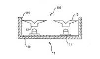
図1aと図1bは、本発明の第一の実施例に係る図である。図1aは、第一の実施例における照明装置を示す図である。照明装置1は、キャビティ10、光源11、光拡散デバイス12及び第一の光学調節面13と含む。キャビティ10は、光拡散面101と出光領域102を含む。光拡散面101は、キャビティ10の内壁に設置される。光源11は、照明装置1に光束を提供する。光拡散デバイス12は、均一な照明を生成できるように、光源11からの光束を分散する。 1a and 1b are diagrams according to a first embodiment of the present invention. FIG. 1a is a diagram showing an illumination device in the first embodiment. The illumination device 1 includes a
光源11からの光束(図示せず)が光拡散面101に入射する場合、光束は光拡散面101により拡散され、できる限りに均一に分散される。光拡散面101は、均等拡散面と実質的に相似することが好ましい。任意の角度から観察しても、均等拡散面により拡散される光束は、同じ強度を有するので、拡散される光束と光源11からの元の光束とを区別することが難しい。即ち、光束は、均一的に分散される。また、光拡散面101は、反射面により代用されることができる。キャビティ10は、照明装置1を形成するハウジングにより、或いは、他の構造、例えば照明装置1を収納するためのバックライトモジュールのベゼル或いはフレームにより閉じ込まれる区間である。 When a light beam (not shown) from the
光源11は、一つ以上の発光装置を含む。発光装置は、一つ以上の色の光束を発する。異なる色の光束の混合は、それぞれの光束の混合割合に基づき、元の色と異なる色の多様な光束を生成することができる。光源11は、赤、青及び緑の三原色の光束を発することが好ましい。割合を調整して三原色を混合することは、白光のみならず多様な色の光束を発することができる。光源11は、点光源、線光源、或いは平面光源である。平面光源は、例えばLED、レーザダイオード(LD)、冷陰極蛍光ランプ(Cold Cathode Fluorescent Lamp:CCFL)、ハロゲンバルブ、或いは有機LED(OLED)などである。従って、ライトスポットの無い均一光束は、光拡散デバイス12の下にある光源11を適度に配置し、光源11と光拡散デバイス12との間の距離を調整することにより、生成されることができる。 The
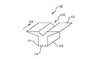
図1bは、第一の実施例における照明装置の光拡散デバイス12を示す拡大図である。光拡散デバイス12は、翼状突起部121、凹部122及び光入射面123を含む。光拡散デバイス12は、縦方向124に沿って延伸することが好ましい。凹部122は、光入射面123から離れて位置する。凹部122は、光入射面123の反対側に位置することが好ましい。第一の光学調節面13は、第一の波状配列131を含む。第一の波状配列131は、光束をより均一的に分散し、顕著なライトスポットまたは混合されていない他の色の光束が見えることを避ける。光入射面123を通過し、光拡散デバイス12に入射した光束は、凹部122と周囲の光学媒体との間の表面において全反射により反射され、凹部122の両側に、即ち、翼状突起部121に入射する。しかし、光束の一部は、凹部122から直接射出する。光拡散デバイス12と周囲の光学媒体との間の屈折率の差により、光拡散デバイス12の外表面から射出する光束は、スネルの法則に基づき屈折される。凹部122に反射される光束の一部は、翼状突起部121に入射するので、凹部122から直接射出する光束が少なくなる。これにより、光源11からの光束の大部分は凹部122から射出し、ライトスポットを生成することを避ける。凹部122の形は、図1bに示すように、V状或いはU状と相似することが好ましい。凹部122はV状である場合、凹部122の頂点は、光入射面123に向うことが好ましい。凹部122に翼状突起部121へ反射される光束、及び/又は、凹部122に反射されなく、翼状突起部121に入射する光束は、直接通過、屈折及び反射を含む方法で光拡散デバイス12から射出する。なお、それらの三つの方法に限ることは無い。例えば、特定な角度で光拡散デバイス12に入射する光束は、翼状突起部内に何回全反射され、徐々に混合され、そして、よく混合される色の光束として、光拡散デバイス12から射出する。更に、光入射面123は、平面、凹面、或いは光を受け入れる他の曲面を含むものの、それらに限ることは無い。 FIG. 1b is an enlarged view showing the
本発明において、第一の光学調節面13は、状況に応じて、光束を拡散するために使用される。図1bに示すように、第一の光学調節面13は、第一の波状配列131を含む。本実施例において、第一の光学調節面13と第一の波状配列131は、光拡散デバイス12の光入射面123に形成される。第一の波状配列131は、第一の光学調節面13に形成される波状の表面であり、この波状の表面は、所定の波の進行方向に、即ち、第一の波状配列131の配列方向に沿って形成される。第一の波状配列131は、複数のマイクロレンズを含むことができる。光束は、第一の光学調節面13を通過する際に、第一の波状配列131のマイクロレンズにより再導向され拡散される。マイクロレンズの直径は、約50μm〜60μmの間の値である。第一の波状配列131の波は連続的に形成される場合、二つの連続的な波の峰或いは谷の間の距離は、約100μm〜120μmの間の値である。 In the present invention, the first
更に、第一の光学調節面13は、異なる屈折率を持つ二つの材料の結合界面に波状配列を形成することにより、光拡散デバイス12内に形成されることができる。第一の波状配列131は、光入射面123に形成されるのみにならず、翼状突起部121又は/及び凹部122に形成されることができる。即ち、第一の波状配列131は、光束の通過可能な任意経路に形成されても良い。 Furthermore, the first
光拡散デバイス12の材料は、アクリル樹脂、COC、PMMA、PC、PC/PMMA、ポリエーテルイミド、フッ素樹脂、シリコン、或いは、それらの組み合わせを含んでも、それらに限ることが無い。又は、光拡散デバイス12の材料は、他の任意の透明材料であっても良い。 The material of the
図2aと図2bは、本発明の第二の実施例における照明装置を示す図である。 2a and 2b are views showing an illumination device in a second embodiment of the present invention.
照明装置1は、状況に応じて、反対する第一の表面151と第二の表面152とを含む光学フィルム15を有する。本実施例の光学調節面13は、第一の表面151に形成される。光学フィルム15は、照明装置1の出光領域102に、或いは、光拡散デバイス12と光源11の間に設置される。第一の実施例に示すように、光学フィルム15は、光束を拡散することができる。状況に応じて、第二の光学調節面14は、光学フィルムの第二の表面に形成されることができる。この場合、第二の波状配列141は、第二の光調整面14に形成される。第一の波状配列の配列方向は、第二の波状配列方向と異なる。図2bに示すように、干渉模様は、第一の波状配列131と第二の波状配列141とを異なる配列方向で積み重ねることにより、生成される。第一の波状配列131と第二の波状配列142を適度に調整することにより、干渉模様を通過する光束は、再分散されることができる。光学フィルム15は、S-Light Opt Electronics Inc., Taiwanにより生産される。また、光束の拡散効果を更に向上するために、一つ以上の拡散板を光学フィルム15上に配置しても良い。 The illuminating device 1 has the
第一の光学調節面13は、光拡散デバイス12と光学フィルムとの何れかに、或いは、それらの両方に形成されることができる。第一の波状配列131と第二の波状配列141は、光源の種類と照明装置1の照明要求により、同じ或いは異なる波のサイズ(マイクロレンズのサイズ)、波の形状及び波の周期を有しても良い。 The first optical adjusting
図3aと図3bは、本発明の第三の実施例における照明装置を示す図である。 3a and 3b are views showing an illumination device in the third embodiment of the present invention.
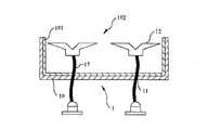
光源11からの光束は、一般的に、多種多様な方向に沿って周囲に入射する。よって、光束の一部は、光拡散デバイス12を通過せず、キャビティ10に直接入射することがある。光拡散デバイス12に入射しない光束を収集するために、本発明の照明装置1は、自光源11からの光束を収集する集光手段16を有する。集光手段16は、光源11と光拡散デバイス12との間に配置される。また、第一の光学調節面13は、集光手段16に形成されてもよい。第一の光学調節面13は、光源11に対向する集光手段16の片側に形成される場合、集光手段16の他の側は、光拡散デバイス12に直接付着されることができる。よって、集光手段16と光拡散デバイス12とは、一体として形成されることができる。また、第一の光学調節面13は、光拡散デバイス12に対向する集光手段16の片側に形成されても良い。集光手段16は、光源11にあわせる溝を有しても良いので、光源11からの光束の大部分は、集光手段16に入射することができる。 The light beam from the
照明装置1の光源11は、キャビティ10内に設置されるのみにならず、キャビティ10の外部に設置されても良い。光源11はキャビティ10の外部に設置される場合、光伝送手段17は、光源11からの光束を光拡散デバイス12に伝送することができる。光伝送手段17は、光学ファイバー或いはライトパイプ等であっても良い。光伝送手段17の一つの端部は、集光手段16と接続されることができる。光伝送手段17と光源11は共にキャビティ10内に設置されることができる。また、光伝送手段17は柔軟材からなる場合、光源11は、光伝送手段17が届ける他の領域に配置されても良い。 The
光源の配置方向は第一の波状配列131の配列方向(即ち、波状配列の波面方向)と平行する場合、第一の波状配列131の波面方向と実質的平行するライトパターン18は、光束が第一の波状配列131を通過した後に、生成される。従って、図4aから4cに示すように、光源11の配置方向と第一の波状配列131の波面方向とが線パターンで配置される場合、光束が線パターンとして分散され、また、光源11の配置方向と第一の波状配列131の波面方向とが曲線パターンまたは放射線パターンで配置される場合、光束が曲線パターンまたは放射線パターンとして分散される。理論的に、光源11の配置方向は第一の波状配列131の波面方向と実質的に平行する場合、光源11からの光束は、波面方向に延伸するライトパターン18に分散される。なお、図4aから4cにおいて、光源11と第一の波状配列131との寸法関係は、実際のものではない。 When the arrangement direction of the light source is parallel to the arrangement direction of the first wave array 131 (that is, the wave front direction of the wave array), the
図2bに示すように、第二の波状配列141は、第一の波状配列131の上に形成されることができる。第二の波状配列141の波面方向は第一の波状配列131の波面方向と異なる場合、光束は、異なる方向に分散されることができる。例えば、第一の波状配列131の波面方向は、第二の波状配列141の波面方向と垂直し、光源11は、線的に配置される場合、光束は、第一の波状配列131を通過した後に線パターンとして分散され、それから、第二の波状配列141を通過した後に平面パターンとして分散される。 As shown in FIG. 2 b, the second
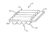
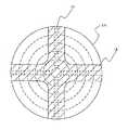
図5に示すように、光源11と第一の波状配列131を使用することにより、点光源は、線光源、例えば、CCFL或いは蛍光灯と相似する機能を実現することができる。一例としては、光源11として使用される複数の点光源が凹状キャビティ19に配置され、第一の波状配列13が光源11の上に設けられる。光源11の配置方向と第一の波状配列13の波面方向とは、互いに平行して、線パターンで配置される場合、光源11からの光束は、線パターンとして分散される。必要な電気回路と機械的な要素を設計することにより、CCFL或いは蛍光灯と相似する照明装置が形成されることができる。また、反射面191は、光源11からの光束を反射するために凹状キャビティ19内に形成されても良い。 As shown in FIG. 5, by using the
第一の波状配列131は、凹状キャビティ19に充填される材料、例えば、樹脂からなる。また、第一の波状配列131は、光源11を覆う光学フィルムに形成されても良い。光源11により生成される熱による熱応力を抑えるために、充填材料192は、光学フィルム13と光源11との間に充填されることができる。充填材料192の熱膨張係数は、光学フィルム13の熱膨張係数と異なる。 The first
ゆえに、前述の照明装置1は、LCD等におけるバックライトモジュールに使用されることができる。バックライトモジュールは、直下型である場合、少なくとも光源11と第一の波状配列131とを含む。光源11の配置方向は、第一の波状配列131の波面方向と実質的に平行することが好ましい。状況に応じて、光拡散デバイス12は、光束を分散するために、光源11とLCDの液晶層との間に設けられても良い。バックライトモジュールは、エッジ型である場合、光導向板は、光束をLCDの表示表面に導向するために、使用される必要がある。この場合、光源11は、この光導向板の側面に設けられる。CCFLにより生成される線ライトパターンのようなライトパターンを生成するために、第一の波状配列131の波面方向は、光源11の配置方向と平行するように配置される。第一の波状配列131は、図5に示すように、光源11と一緒にモジュールとして形成されても良い。第一の波状配列131は、光導向板に、例えば光導向板の入光領域(図示せず)に直接形成されることができる。光源11からの光束は、光拡散デバイス12により光導向板へ再導向されても良い。この場合、光拡散デバイス12の翼状突起部121は、この光導向板に対向する。 Therefore, the above-described lighting device 1 can be used for a backlight module in an LCD or the like. When the backlight module is a direct type, it includes at least the
以上、本発明の好ましい実施形態を説明したが、本発明はこの実施形態に限定されず、本発明の趣旨を離脱しない限り、本発明に対するあらゆる変更は本発明の範囲に属する。 The preferred embodiment of the present invention has been described above, but the present invention is not limited to this embodiment, and all modifications to the present invention are within the scope of the present invention unless departing from the spirit of the present invention.
1 照明装置
10 キャビティ
11 光源
12 光拡散デバイス
13 第一の光学調節面
101 光拡散面
102 出光領域
121 翼状突起部
122 凹部
123 光入射面
124 縦方向
14 第二の光学調節面
15 光学フィルム
131 第一の波状配列
141 第二の波状配列
151 第一の表面
152 第二の表面
1803 光束の入射面
16 集光手段
161 溝
17 光伝送手段
18 ライトパターン
19 凹状キャビティ
191 反射面
192 充填材料DESCRIPTION OF SYMBOLS 1
Claims (20)
Translated fromJapanese翼状突起部と、
光入射面と、
前記光入射面から離れて配置される凹部と、
波面方向に形成される波状配列を含む光学調節面と、
を有し、
前記凹部の両側は、前記光入射面を通過して前記光拡散デバイスに入射した光束の一部を反射する、光拡散デバイス。A light diffusing device,
A wing-shaped projection,
A light incident surface;
A recess disposed away from the light incident surface;
An optical adjustment surface including a waved array formed in a wavefront direction;
Have
Both sides of the recess are light diffusing devices that reflect part of the light beam that has passed through the light incident surface and entered the light diffusing device.
請求項1に記載の光拡散デバイス。The optical adjustment surface is formed on the light incident surface.
The light diffusing device according to claim 1.
請求項1に記載の光拡散デバイス。The optical adjustment surface is formed in the recess.
The light diffusing device according to claim 1.
請求項1に記載の光拡散デバイス。The optical adjustment surface is formed on the wing-shaped protrusion.
The light diffusing device according to claim 1.
請求項1に記載の光拡散デバイス。The wing-like protrusion includes a reflective surface,
The light diffusing device according to claim 1.
請求項1に記載の光拡散デバイス。The wing-like protrusion includes a refractive surface,
The light diffusing device according to claim 1.
請求項1に記載の光拡散デバイス。The recess includes a vertex facing the light incident surface,
The light diffusing device according to claim 1.
請求項1に記載の光拡散デバイス。The wing-like protrusion extends in the longitudinal direction;
The light diffusing device according to claim 1.
請求項1に記載の光拡散デバイス。The wavefront direction is substantially parallel to the longitudinal direction;
The light diffusing device according to claim 1.
請求項1に記載の光拡散デバイス。The optical adjusting surface is disposed between two types of materials having different refractive indices;
The light diffusing device according to claim 1.
前記キャビティに設けられる複数の光源と、
前記光源の上方に設置される光拡散デバイスと、
前記光源の上方に設けられ、波状配列を有し、前記底部と実質的に平行する光学調節面と、
を有し、
前記光拡散デバイスは、翼状突起部と、光入射面と、当該光入射面と反対する凹部とを有し、
前記凹部の両側は、前記光入射面を通過して前記光拡散デバイスに入射した光束の一部を反射する、照明装置。A cavity including a bottom and sidewalls;
A plurality of light sources provided in the cavity;
A light diffusing device installed above the light source;
An optical adjustment surface provided above the light source, having a wavy array and substantially parallel to the bottom;
Have
The light diffusing device has a wing-like projection, a light incident surface, and a recess opposite to the light incident surface,
Both sides of the concave portion reflect the part of the light beam that has passed through the light incident surface and entered the light diffusion device.
請求項11に記載の照明装置。A reflective surface formed on at least one of the bottom and the side wall;
The lighting device according to claim 11.
請求項11に記載の照明装置。Including light diffusing means substantially parallel to the bottom,
The lighting device according to claim 11.
請求項11に記載の照明装置。The wing-like protrusion extends in the longitudinal direction;
The lighting device according to claim 11.
請求項11に記載の照明装置。The wavy array includes lenses having a diameter of substantially 50 μm to 60 μm,
The lighting device according to claim 11.
請求項11に記載の照明装置。The light source includes any one of a red light emitting diode, a blue light emitting diode, and a green light emitting diode.
The lighting device according to claim 11.
請求項11に記載の照明装置。The light sources are arranged periodically,
The lighting device according to claim 11.
請求項11に記載の照明装置。The light sources are arranged in an array.
The lighting device according to claim 11.
請求項11に記載の照明装置。The light source is arranged in a curved shape,
The lighting device according to claim 11.
請求項11に記載の照明装置。The light sources are arranged in a cluster,
The lighting device according to claim 11.
Applications Claiming Priority (4)
| Application Number | Priority Date | Filing Date | Title |
|---|---|---|---|
| TW93129157 | 2004-09-24 | ||
| TW093129157 | 2004-09-24 | ||
| TW94114630ATWI249257B (en) | 2004-09-24 | 2005-05-06 | Illumination apparatus |
| TW094114630 | 2005-05-06 |
Related Parent Applications (1)
| Application Number | Title | Priority Date | Filing Date |
|---|---|---|---|
| JP2005276391ADivisionJP2006093148A (en) | 2004-09-24 | 2005-09-22 | Lighting apparatus |
Publications (2)
| Publication Number | Publication Date |
|---|---|
| JP2012113312Atrue JP2012113312A (en) | 2012-06-14 |
| JP5367850B2 JP5367850B2 (en) | 2013-12-11 |
Family
ID=36099195
Family Applications (3)
| Application Number | Title | Priority Date | Filing Date |
|---|---|---|---|
| JP2005276391APendingJP2006093148A (en) | 2004-09-24 | 2005-09-22 | Lighting apparatus |
| JP2005278908AActiveJP5150047B2 (en) | 2004-09-24 | 2005-09-26 | Lighting package |
| JP2012003839AExpired - LifetimeJP5367850B2 (en) | 2004-09-24 | 2012-01-12 | Lighting device |
Family Applications Before (2)
| Application Number | Title | Priority Date | Filing Date |
|---|---|---|---|
| JP2005276391APendingJP2006093148A (en) | 2004-09-24 | 2005-09-22 | Lighting apparatus |
| JP2005278908AActiveJP5150047B2 (en) | 2004-09-24 | 2005-09-26 | Lighting package |
Country Status (5)
| Country | Link |
|---|---|
| US (4) | US7341358B2 (en) |
| JP (3) | JP2006093148A (en) |
| KR (1) | KR100990813B1 (en) |
| DE (2) | DE102005045588B4 (en) |
| TW (1) | TWI249257B (en) |
Cited By (3)
| Publication number | Priority date | Publication date | Assignee | Title |
|---|---|---|---|---|
| WO2014014186A1 (en)* | 2012-07-18 | 2014-01-23 | Lg Innotek Co., Ltd. | Display device and light emitting device |
| KR101997406B1 (en)* | 2018-10-12 | 2019-10-17 | 이현규 | LED sign board |
| KR102057882B1 (en) | 2019-03-06 | 2019-12-20 | 최종영 | channel sign board |
Families Citing this family (203)
| Publication number | Priority date | Publication date | Assignee | Title |
|---|---|---|---|---|
| JP4339143B2 (en)* | 2004-02-10 | 2009-10-07 | 株式会社小糸製作所 | Vehicle lamp unit |
| KR20060012959A (en)* | 2004-08-05 | 2006-02-09 | 삼성전자주식회사 | Backlight for display device |
| TWI249257B (en)* | 2004-09-24 | 2006-02-11 | Epistar Corp | Illumination apparatus |
| DE102005045589A1 (en) | 2004-09-24 | 2006-04-06 | Epistar Corp. | liquid crystal display |
| KR100688767B1 (en)* | 2004-10-15 | 2007-02-28 | 삼성전기주식회사 | Lens for LED Light Source |
| KR100754169B1 (en)* | 2004-11-24 | 2007-09-03 | 삼성전자주식회사 | Side light emitting device, backlight unit using same as light source, and liquid crystal display device employing same |
| TWI313775B (en)* | 2005-01-06 | 2009-08-21 | Au Optronics Corp | Backlight module and illumination device thereof |
| KR100644684B1 (en)* | 2005-02-26 | 2006-11-14 | 삼성전자주식회사 | Straight Side Light Emitter, Backlight System and Liquid Crystal Display Apparatus |
| EP2757401A1 (en)* | 2005-04-26 | 2014-07-23 | LG Innotek Co., Ltd. | Optical lens, light emitting device package using the optical lens, and backlight unit |
| US20060285311A1 (en)* | 2005-06-19 | 2006-12-21 | Chih-Li Chang | Light-emitting device, backlight module, and liquid crystal display using the same |
| US7755811B2 (en)* | 2005-06-30 | 2010-07-13 | Xerox Corporation | Document illuminator |
| KR20070013469A (en)* | 2005-07-26 | 2007-01-31 | 삼성전자주식회사 | Optical lens and optical package, backlight assembly and display device having same |
| TWI260380B (en)* | 2005-08-05 | 2006-08-21 | Chi Lin Technology Co Ltd | Lens for LED |
| US7588359B2 (en)* | 2005-09-26 | 2009-09-15 | Osram Sylvania Inc. | LED lamp with direct optical coupling in axial arrangement |
| KR100788426B1 (en)* | 2005-11-19 | 2007-12-24 | 삼성전자주식회사 | Backlight unit and liquid crystal display including the same |
| JP4600257B2 (en)* | 2005-11-25 | 2010-12-15 | ソニー株式会社 | Light guide plate, backlight device, manufacturing method thereof, and liquid crystal display device |
| TWM291088U (en)* | 2005-12-08 | 2006-05-21 | Upec Electronics Corp | Illuminating device |
| TWI281556B (en)* | 2006-03-15 | 2007-05-21 | Bright Led Electronics Corp | Lens, light-emitting apparatus with lens and its manufacturing method |
| CN100456505C (en)* | 2006-04-10 | 2009-01-28 | 中强光电股份有限公司 | Light emitting module |
| US7390117B2 (en)* | 2006-05-02 | 2008-06-24 | 3M Innovative Properties Company | LED package with compound converging optical element |
| US20070257271A1 (en)* | 2006-05-02 | 2007-11-08 | 3M Innovative Properties Company | Led package with encapsulated converging optical element |
| US20070258241A1 (en)* | 2006-05-02 | 2007-11-08 | 3M Innovative Properties Company | Led package with non-bonded converging optical element |
| US20070257270A1 (en)* | 2006-05-02 | 2007-11-08 | 3M Innovative Properties Company | Led package with wedge-shaped optical element |
| US7525126B2 (en)* | 2006-05-02 | 2009-04-28 | 3M Innovative Properties Company | LED package with converging optical element |
| US7805048B2 (en)* | 2006-05-10 | 2010-09-28 | Cree, Inc. | Methods and apparatus for directing light emitting diode output light |
| WO2007139781A2 (en) | 2006-05-23 | 2007-12-06 | Cree Led Lighting Solutions, Inc. | Lighting device |
| US7952110B2 (en)* | 2006-06-12 | 2011-05-31 | 3M Innovative Properties Company | LED device with re-emitting semiconductor construction and converging optical element |
| KR100820975B1 (en)* | 2006-06-13 | 2008-04-10 | 엘지전자 주식회사 | Surface light source device, backlight unit and liquid crystal display device having same |
| TWI298095B (en)* | 2006-07-04 | 2008-06-21 | Coretronic Corp | Light emitting device |
| US7254309B1 (en)* | 2006-07-14 | 2007-08-07 | Coretronic Corporation | Side emitting LED and lens |
| WO2008011377A2 (en)* | 2006-07-17 | 2008-01-24 | 3M Innovative Properties Company | Led package with converging extractor |
| DE102006034070A1 (en)* | 2006-07-20 | 2008-01-31 | Schefenacker Vision Systems Germany Gmbh | Light unit with a light-emitting diode with integrated Lichtumlenkkörper |
| WO2008035485A1 (en)* | 2006-09-21 | 2008-03-27 | Sharp Kabushiki Kaisha | Backlight unit and liquid crystal display device |
| CN101150158A (en)* | 2006-09-21 | 2008-03-26 | 鸿富锦精密工业(深圳)有限公司 | Light-emitting diode and its preparation method |
| TW200823558A (en)* | 2006-11-23 | 2008-06-01 | Lite On Technology Corp | Light source unit and backlight module with the light source unit |
| JP4853252B2 (en)* | 2006-11-27 | 2012-01-11 | 日亜化学工業株式会社 | Lighting device |
| CN101206271B (en)* | 2006-12-19 | 2012-04-11 | 香港应用科技研究院有限公司 | Total reflection side emission coupling device |
| RU2009128624A (en)* | 2006-12-29 | 2011-02-10 | Ой Модинес Лтд (Fi) | INPUT LIGHT STRUCTURE FOR LIGHT CONDUCTOR DEVICES |
| US20090067175A1 (en)* | 2007-01-04 | 2009-03-12 | Bright Led Electronics Corp. | Lens for use with a light-emitting element and light source device including the lens |
| DE102007002403B4 (en)* | 2007-01-17 | 2016-03-03 | Osram Gmbh | Lighting arrangement, multiple light module, luminaire and their use |
| KR100851146B1 (en)* | 2007-02-05 | 2008-08-08 | 엘지이노텍 주식회사 | Surface light source device and display device using same |
| TWI410711B (en)* | 2007-03-27 | 2013-10-01 | Cpt Technology Group Co Ltd | Back light module and liquid crystal display having the same |
| RU2456503C2 (en)* | 2007-04-05 | 2012-07-20 | Конинклейке Филипс Электроникс Н.В. | Light beam former |
| KR100870065B1 (en)* | 2007-04-11 | 2008-11-24 | 알티전자 주식회사 | Method of manufacturing lens for LED package |
| US7554742B2 (en)* | 2007-04-17 | 2009-06-30 | Visteon Global Technologies, Inc. | Lens assembly |
| US7967477B2 (en)* | 2007-09-06 | 2011-06-28 | Philips Lumileds Lighting Company Llc | Compact optical system and lenses for producing uniform collimated light |
| CN101459211B (en) | 2007-12-11 | 2011-03-02 | 富士迈半导体精密工业(上海)有限公司 | Solid illuminating device |
| EP2081172A1 (en)* | 2008-01-18 | 2009-07-22 | G-LEC Europe GmbH | Display panel and display system |
| JP2009195273A (en)* | 2008-02-19 | 2009-09-03 | Sanyo Electric Co Ltd | Showcase |
| CN101246945B (en)* | 2008-02-29 | 2010-06-16 | 北京大学 | An edge-emitting LED packaging structure |
| JP4470071B2 (en)* | 2008-03-03 | 2010-06-02 | フェリカネットワークス株式会社 | Card issuing system, card issuing server, card issuing method and program |
| JP5150335B2 (en)* | 2008-03-28 | 2013-02-20 | スタンレー電気株式会社 | Light guiding lens |
| US8388193B2 (en)* | 2008-05-23 | 2013-03-05 | Ruud Lighting, Inc. | Lens with TIR for off-axial light distribution |
| US8348475B2 (en) | 2008-05-23 | 2013-01-08 | Ruud Lighting, Inc. | Lens with controlled backlight management |
| EP2993387A1 (en)* | 2008-05-23 | 2016-03-09 | Cree, Inc. | Recessed led lighting fixture |
| TWI381134B (en)* | 2008-06-02 | 2013-01-01 | 榮創能源科技股份有限公司 | Led lighting module |
| US7766509B1 (en) | 2008-06-13 | 2010-08-03 | Lumec Inc. | Orientable lens for an LED fixture |
| US8002435B2 (en)* | 2008-06-13 | 2011-08-23 | Philips Electronics Ltd Philips Electronique Ltee | Orientable lens for an LED fixture |
| DE202008008977U1 (en)* | 2008-07-04 | 2009-11-19 | Pasedag, Roland | Lighting fixture, in particular in the form of a rescue sign luminaire |
| US8016446B2 (en)* | 2008-07-04 | 2011-09-13 | Hon Hai Precision Industry Co., Ltd. | Optical plate and backlight module using the same |
| US20100002432A1 (en)* | 2008-07-07 | 2010-01-07 | Hubbell Incorporated | Indirect luminaire utilizing led light sources |
| US20100073927A1 (en)* | 2008-09-21 | 2010-03-25 | Ian Lewin | Lens for Solid-State Light-Emitting Device |
| US8662716B2 (en)* | 2008-11-18 | 2014-03-04 | Orafol Americas Inc. | Side-emitting optical elements and methods thereof |
| EP2377112B1 (en)* | 2008-12-09 | 2013-02-20 | Koninklijke Philips Electronics N.V. | Lighting system with fiber diffusing element |
| JP4655155B2 (en)* | 2009-01-26 | 2011-03-23 | ソニー株式会社 | Light emitting device and image display device |
| US8246212B2 (en)* | 2009-01-30 | 2012-08-21 | Koninklijke Philips Electronics N.V. | LED optical assembly |
| TW201030281A (en)* | 2009-02-13 | 2010-08-16 | Ama Precision Inc | Light-emitting apparatus and light-guiding member thereof |
| US8576406B1 (en) | 2009-02-25 | 2013-11-05 | Physical Optics Corporation | Luminaire illumination system and method |
| TW201031950A (en)* | 2009-02-26 | 2010-09-01 | xue-zhong Gao | Reflection component of light-emitting element |
| US9255686B2 (en) | 2009-05-29 | 2016-02-09 | Cree, Inc. | Multi-lens LED-array optic system |
| WO2011029127A1 (en)* | 2009-09-10 | 2011-03-17 | Jeffrey Kenneth Procter | A lighting assembly |
| USD619756S1 (en)* | 2009-09-17 | 2010-07-13 | Foxsemicon Integrated Technology, Inc. | Optical lens for LED |
| USD619755S1 (en)* | 2009-09-17 | 2010-07-13 | Foxsemicon Integrated Technology, Inc. | Optical lens for LED |
| USD662530S1 (en)* | 2009-09-17 | 2012-06-26 | Foxsemicon Integrated Technology, Inc. | Optical lens |
| US8721101B2 (en)* | 2009-09-21 | 2014-05-13 | Koninklijke Philips N.V. | Light emitting device comprising a light guide plate with reflective shielding with glare reduction |
| TWI396310B (en)* | 2009-10-02 | 2013-05-11 | Everlight Electronics Co Ltd | Light-emitting diode structure |
| JP5023134B2 (en)* | 2009-10-27 | 2012-09-12 | 株式会社遠藤照明 | LED light distribution lens, LED illumination module including the LED light distribution lens, and lighting fixture including the LED illumination module |
| WO2011055467A1 (en)* | 2009-11-04 | 2011-05-12 | ナルックス株式会社 | Lighting device |
| JP5295382B2 (en)* | 2009-11-09 | 2013-09-18 | 三菱電機株式会社 | Planar light source device and display device using the same |
| USD617937S1 (en)* | 2009-12-22 | 2010-06-15 | U.S. Led, Ltd. | M-shaped lens for an LED lighting fixture |
| CZ309346B6 (en)* | 2010-11-01 | 2022-09-14 | Varroc Lighting Systems, s.r.o. | Light guiding module with adjustable illumination of the contour surface |
| TWI418854B (en)* | 2010-03-16 | 2013-12-11 | Cal Comp Electronics & Comm Co | Lens structure |
| EP2375130B1 (en)* | 2010-04-09 | 2014-07-02 | Thorn Europhane S.A. | Lighting module for tunnel, road or street light |
| WO2012011304A1 (en)* | 2010-07-23 | 2012-01-26 | シャープ株式会社 | Light guiding body, light source unit, illumination device, and display device |
| JP5512447B2 (en) | 2010-07-27 | 2014-06-04 | シャープ株式会社 | lighting equipment |
| US10451251B2 (en)* | 2010-08-02 | 2019-10-22 | Ideal Industries Lighting, LLC | Solid state lamp with light directing optics and diffuser |
| KR20120014325A (en)* | 2010-08-09 | 2012-02-17 | 삼성엘이디 주식회사 | Optical lenses and lighting devices |
| CN102374418B (en) | 2010-08-20 | 2014-08-20 | 光宝电子(广州)有限公司 | Luminous diode light fixture |
| CN102374419A (en)* | 2010-08-20 | 2012-03-14 | 光宝科技股份有限公司 | Led lamp |
| US8975806B2 (en)* | 2010-08-31 | 2015-03-10 | Toshiba Lighting & Technology Corporation | Bulb-type lamp |
| US10883702B2 (en) | 2010-08-31 | 2021-01-05 | Ideal Industries Lighting Llc | Troffer-style fixture |
| US9075172B2 (en)* | 2010-09-20 | 2015-07-07 | Luxingtek, Ltd. | Light converting optical structure and lighting device utilizing the same |
| US8814391B2 (en)* | 2010-09-20 | 2014-08-26 | Luxingtek, Ltd. | Light guiding structure |
| CN101936476B (en)* | 2010-09-24 | 2013-06-05 | 鸿富锦精密工业(深圳)有限公司 | Three-color optical mixing LED point light source device |
| WO2012042436A1 (en)* | 2010-09-29 | 2012-04-05 | Koninklijke Philips Electronics N.V. | Tir optics with optimized incoupling structure |
| WO2012042460A1 (en)* | 2010-09-29 | 2012-04-05 | Koninklijke Philips Electronics N.V. | Tube luminescent retrofit using high power light emitting diodes |
| US20120092887A1 (en)* | 2010-10-15 | 2012-04-19 | Shenzhen China Star Optoelectronics Technology Co., Ltd. | Backlight module and display apparatus |
| WO2012073156A1 (en)* | 2010-11-30 | 2012-06-07 | Koninklijke Philips Electronics N.V. | Light redirecting and diffusing module for light emitting diodes |
| US8297799B2 (en)* | 2010-12-02 | 2012-10-30 | Aether Systems Inc. | Omnidirectional LED lamp and complex, unitary lens |
| TWI407052B (en)* | 2010-12-21 | 2013-09-01 | Aether Systems Inc | Omnidirectional led lamp |
| US9581312B2 (en)* | 2010-12-06 | 2017-02-28 | Cree, Inc. | LED light fixtures having elongated prismatic lenses |
| US9494293B2 (en) | 2010-12-06 | 2016-11-15 | Cree, Inc. | Troffer-style optical assembly |
| JP5643670B2 (en)* | 2011-02-03 | 2014-12-17 | 株式会社エンプラス | Luminous flux control member and lighting device |
| DE102011000652A1 (en) | 2011-02-11 | 2012-08-16 | Vossloh-Schwabe Optoelectronic Gmbh & Co. Kg | Reflector for lighting |
| CN102691890A (en)* | 2011-03-21 | 2012-09-26 | 欧司朗股份有限公司 | Omnidirectional lighting device |
| JP5555927B2 (en) | 2011-03-25 | 2014-07-23 | ナルックス株式会社 | Lighting device |
| WO2012132043A1 (en)* | 2011-03-25 | 2012-10-04 | ナルックス株式会社 | Illumination device |
| JP5172988B2 (en)* | 2011-04-12 | 2013-03-27 | シャープ株式会社 | Lighting device |
| US20130258656A1 (en)* | 2011-05-19 | 2013-10-03 | Huei-dung Chin | Modulated LED light tube |
| USD664286S1 (en)* | 2011-05-24 | 2012-07-24 | Aether Systems Inc. | LED lens |
| US8696173B2 (en)* | 2011-06-08 | 2014-04-15 | GE Lighting Solutions, LLC | Low profile lamp using TIR lens |
| TWM415245U (en)* | 2011-06-30 | 2011-11-01 | Chun Kuang Optics Corp | Optic element and lighting device comprising the optic element |
| US8876325B2 (en)* | 2011-07-01 | 2014-11-04 | Cree, Inc. | Reverse total internal reflection features in linear profile for lighting applications |
| US10823347B2 (en) | 2011-07-24 | 2020-11-03 | Ideal Industries Lighting Llc | Modular indirect suspended/ceiling mount fixture |
| US8757845B2 (en)* | 2011-07-29 | 2014-06-24 | TSMC Solid State Lighting, Ltd. | Wide angle based indoor lighting lamp |
| CN103858244B (en)* | 2011-08-08 | 2018-08-10 | 夸克星有限责任公司 | Lighting device comprising a plurality of light emitting elements |
| US9081125B2 (en) | 2011-08-08 | 2015-07-14 | Quarkstar Llc | Illumination devices including multiple light emitting elements |
| JP2013045651A (en)* | 2011-08-24 | 2013-03-04 | Panasonic Corp | lighting equipment |
| US8523407B2 (en) | 2011-09-13 | 2013-09-03 | Chun Kuang Optics Corp. | Optical element and illuminant device using the same |
| JP5683421B2 (en)* | 2011-09-27 | 2015-03-11 | 株式会社ジャパンディスプレイ | Lighting device |
| JP2013101901A (en)* | 2011-10-20 | 2013-05-23 | Toshiba Corp | Flat lamp device |
| TW201326890A (en)* | 2011-12-22 | 2013-07-01 | Dongguan Ledlink Optics Inc | Uniform lens |
| US10544925B2 (en) | 2012-01-06 | 2020-01-28 | Ideal Industries Lighting Llc | Mounting system for retrofit light installation into existing light fixtures |
| USD674965S1 (en)* | 2012-01-27 | 2013-01-22 | Hubbell Incorporated | LED optical component |
| US9777897B2 (en) | 2012-02-07 | 2017-10-03 | Cree, Inc. | Multiple panel troffer-style fixture |
| US9541257B2 (en) | 2012-02-29 | 2017-01-10 | Cree, Inc. | Lens for primarily-elongate light distribution |
| US10408429B2 (en) | 2012-02-29 | 2019-09-10 | Ideal Industries Lighting Llc | Lens for preferential-side distribution |
| US9541258B2 (en) | 2012-02-29 | 2017-01-10 | Cree, Inc. | Lens for wide lateral-angle distribution |
| US9255688B2 (en)* | 2012-03-06 | 2016-02-09 | Fraen Corporation | Oscillating interface for light mixing lenses |
| US9494294B2 (en) | 2012-03-23 | 2016-11-15 | Cree, Inc. | Modular indirect troffer |
| US9310038B2 (en) | 2012-03-23 | 2016-04-12 | Cree, Inc. | LED fixture with integrated driver circuitry |
| USD729858S1 (en)* | 2012-03-29 | 2015-05-19 | Sony Corporation | Lens |
| US9054019B2 (en) | 2012-04-02 | 2015-06-09 | Cree, Inc. | Low profile lighting module with side emitting LEDs |
| US9874322B2 (en) | 2012-04-10 | 2018-01-23 | Cree, Inc. | Lensed troffer-style light fixture |
| CN103378280B (en)* | 2012-04-28 | 2017-12-15 | 陈玉玲 | Lenses for LEDs |
| USD697664S1 (en) | 2012-05-07 | 2014-01-14 | Cree, Inc. | LED lens |
| CN102705776A (en)* | 2012-05-16 | 2012-10-03 | 广州市鸿利光电股份有限公司 | Lens realizing even and rectangular facula |
| TW201408946A (en)* | 2012-08-21 | 2014-03-01 | 辰峯光電股份有限公司 | Light emitting apparatus |
| WO2014043369A2 (en) | 2012-09-13 | 2014-03-20 | Quarkstar Llc | Devices for workspace illumination |
| EP2895794B1 (en) | 2012-09-13 | 2018-06-27 | Quarkstar LLC | Illumination systems providing direct and indirect illumination |
| DE102012109111A1 (en)* | 2012-09-26 | 2014-04-17 | Osram Gmbh | Optical arrangement and lighting device with optical arrangement |
| CN104718410A (en)* | 2012-10-19 | 2015-06-17 | 皇家飞利浦有限公司 | Lighting device for indirect illumination |
| WO2014087278A1 (en)* | 2012-12-03 | 2014-06-12 | Koninklijke Philips N.V. | Light emitting arrangement using light guides. |
| US8864346B2 (en)* | 2012-12-10 | 2014-10-21 | GE Lighting Solutions, LLC | Lens-reflector combination for batwing light distribution |
| US8944660B2 (en)* | 2013-01-23 | 2015-02-03 | Ledil Oy | Light guide |
| US9206956B2 (en) | 2013-02-08 | 2015-12-08 | Quarkstar Llc | Illumination device providing direct and indirect illumination |
| US10162098B2 (en)* | 2013-02-13 | 2018-12-25 | Quarkstar Llc | Solid-state luminaire |
| USD732709S1 (en) | 2013-03-13 | 2015-06-23 | GE Lighting Solutions, LLC | LED lamp with an elevated light unit |
| US10648643B2 (en) | 2013-03-14 | 2020-05-12 | Ideal Industries Lighting Llc | Door frame troffer |
| US9052075B2 (en) | 2013-03-15 | 2015-06-09 | Cree, Inc. | Standardized troffer fixture |
| USD718490S1 (en) | 2013-03-15 | 2014-11-25 | Cree, Inc. | LED lens |
| JP5403775B1 (en) | 2013-03-27 | 2014-01-29 | 株式会社光波 | Lighting device and display device |
| KR101524914B1 (en) | 2013-03-28 | 2015-06-01 | 엘지이노텍 주식회사 | Light diffusion device, and light emitting device array unit having the same |
| KR20140123134A (en)* | 2013-04-10 | 2014-10-22 | 삼성전자주식회사 | Reflective diffusion lens and lighting installation |
| WO2014172571A2 (en) | 2013-04-19 | 2014-10-23 | Quarkstar Llc | Illumination devices with adjustable optical elements |
| US10262462B2 (en)* | 2014-04-18 | 2019-04-16 | Magic Leap, Inc. | Systems and methods for augmented and virtual reality |
| CN104279506A (en)* | 2013-07-04 | 2015-01-14 | 展晶科技(深圳)有限公司 | Optical lens and light-emitting element using the optical lens |
| US9010951B2 (en) | 2013-07-05 | 2015-04-21 | Lg Innotek Co., Ltd. | Optical lens, light emitting device, and display |
| JP5685706B1 (en)* | 2013-07-10 | 2015-03-18 | ナルックス株式会社 | Optical element |
| DE102013011877B4 (en)* | 2013-07-17 | 2016-02-25 | Erco Gmbh | Luminaire with a collimator optics |
| EP3422059B1 (en) | 2013-07-18 | 2025-09-03 | Quarkstar LLC | Illumination device in which source light injection is non-parallel to device's optical axis |
| CN104344333A (en)* | 2013-07-30 | 2015-02-11 | 展晶科技(深圳)有限公司 | Optical lens and light-emitting element using the optical lens |
| US9608177B2 (en)* | 2013-08-27 | 2017-03-28 | Lumens Co., Ltd. | Light emitting device package and backlight unit having the same |
| USD786471S1 (en) | 2013-09-06 | 2017-05-09 | Cree, Inc. | Troffer-style light fixture |
| KR101413241B1 (en)* | 2013-09-13 | 2014-06-27 | 주식회사 쏠라사이언스 | Led lighting apparatus having light distribution lens |
| CN105723150B (en) | 2013-09-17 | 2019-02-22 | 夸克星有限责任公司 | Light guide lighting fixture with light divergence modifier |
| US9435504B2 (en)* | 2013-10-30 | 2016-09-06 | Ford Global Technologies, Llc | Apparatus for radiating light from a virtual source |
| CN103591509B (en)* | 2013-11-08 | 2015-09-09 | 京东方科技集团股份有限公司 | A kind of backlight source and display device |
| WO2015071985A1 (en)* | 2013-11-13 | 2015-05-21 | アジアブリッジジャパン株式会社 | Light-emitting device |
| JP2015207754A (en) | 2013-12-13 | 2015-11-19 | 日亜化学工業株式会社 | Light emitting device |
| CN104713034A (en)* | 2013-12-17 | 2015-06-17 | 富泰华精密电子(郑州)有限公司 | Backlight module |
| US9523479B2 (en) | 2014-01-03 | 2016-12-20 | Cree, Inc. | LED lens |
| US10451253B2 (en) | 2014-02-02 | 2019-10-22 | Ideal Industries Lighting Llc | Troffer-style fixture with LED strips |
| USD772465S1 (en) | 2014-02-02 | 2016-11-22 | Cree Hong Kong Limited | Troffer-style fixture |
| USD807556S1 (en) | 2014-02-02 | 2018-01-09 | Cree Hong Kong Limited | Troffer-style fixture |
| US10527225B2 (en) | 2014-03-25 | 2020-01-07 | Ideal Industries, Llc | Frame and lens upgrade kits for lighting fixtures |
| TWI536077B (en)* | 2014-04-09 | 2016-06-01 | 友達光電股份有限公司 | Optical assembly and back light module |
| KR102244427B1 (en)* | 2014-06-02 | 2021-04-27 | 엘지이노텍 주식회사 | Lighting device |
| AT515790B1 (en)* | 2014-06-11 | 2015-12-15 | Zizala Lichtsysteme Gmbh | Lighting device for a motor vehicle and vehicle headlights with lighting device |
| US9784433B2 (en)* | 2014-09-30 | 2017-10-10 | The Boeing Company | Optical devices for light mixing |
| US11306897B2 (en) | 2015-02-09 | 2022-04-19 | Ecosense Lighting Inc. | Lighting systems generating partially-collimated light emissions |
| US10801696B2 (en) | 2015-02-09 | 2020-10-13 | Ecosense Lighting Inc. | Lighting systems generating partially-collimated light emissions |
| US10302278B2 (en)* | 2015-04-09 | 2019-05-28 | Cree, Inc. | LED bulb with back-reflecting optic |
| JP2016213051A (en)* | 2015-05-08 | 2016-12-15 | 株式会社エンプラス | Surface light source device |
| US10012354B2 (en) | 2015-06-26 | 2018-07-03 | Cree, Inc. | Adjustable retrofit LED troffer |
| WO2017022143A1 (en)* | 2015-08-05 | 2017-02-09 | 株式会社パトライト | Lens component and light-emitting device |
| US9806242B2 (en)* | 2015-09-23 | 2017-10-31 | Hon Hai Precision Industry Co., Ltd. | Optical lens for light emitting diode device |
| US10253948B1 (en) | 2017-03-27 | 2019-04-09 | EcoSense Lighting, Inc. | Lighting systems having multiple edge-lit lightguide panels |
| US11585515B2 (en) | 2016-01-28 | 2023-02-21 | Korrus, Inc. | Lighting controller for emulating progression of ambient sunlight |
| US12385623B2 (en) | 2016-01-28 | 2025-08-12 | Korrus, Inc. | Beam-shaping lighting systems |
| US11635188B2 (en) | 2017-03-27 | 2023-04-25 | Korrus, Inc. | Lighting systems generating visible-light emissions for dynamically emulating sky colors |
| WO2018066418A1 (en)* | 2016-10-04 | 2018-04-12 | 株式会社エンプラス | Light bundle control member, light emitting device, and illuminating device |
| JP2018061024A (en)* | 2016-10-04 | 2018-04-12 | 株式会社エンプラス | Luminous flux control member, light emitting device, and illumination device |
| US10468566B2 (en) | 2017-04-10 | 2019-11-05 | Ideal Industries Lighting Llc | Hybrid lens for controlled light distribution |
| JP2019040859A (en)* | 2017-08-22 | 2019-03-14 | 株式会社エンプラス | Light emitting device, surface light source device, and light flux controlling member |
| CN108198844A (en)* | 2018-01-03 | 2018-06-22 | 京东方科技集团股份有限公司 | A kind of display panel, its production method and display device |
| JP6703312B2 (en)* | 2018-05-31 | 2020-06-03 | 日亜化学工業株式会社 | Light emitting module and surface emitting light source |
| CN110693392A (en)* | 2018-07-10 | 2020-01-17 | 添可电器有限公司 | Hand-held vacuum cleaner |
| WO2020057514A1 (en)* | 2018-09-17 | 2020-03-26 | 欧普照明股份有限公司 | Illumination lamp, illumination module, and lens |
| JP7231831B2 (en) | 2019-10-30 | 2023-03-02 | 日亜化学工業株式会社 | Light source device |
| JP7148813B2 (en)* | 2019-10-30 | 2022-10-06 | 日亜化学工業株式会社 | Light source device |
| US11587362B2 (en) | 2020-12-16 | 2023-02-21 | Lenovo (Singapore) Pte. Ltd. | Techniques for determining sign language gesture partially shown in image(s) |
| US12253222B2 (en) | 2021-06-04 | 2025-03-18 | Signify Holding B.V. | Multi-color mixing and shaping optic and system |
Citations (5)
| Publication number | Priority date | Publication date | Assignee | Title |
|---|---|---|---|---|
| JPH03230586A (en)* | 1990-02-05 | 1991-10-14 | Mitsubishi Cable Ind Ltd | LED module |
| JPH0555567U (en)* | 1991-12-24 | 1993-07-23 | スタンレー電気株式会社 | LED surface light source device |
| JPH10506725A (en)* | 1994-10-04 | 1998-06-30 | ミネソタ マイニング アンド マニュファクチャリング カンパニー | Self-contained lighting type marking device |
| JP2000147264A (en)* | 1998-11-05 | 2000-05-26 | Mitsubishi Chemicals Corp | Light control sheet and surface light source device using the same |
| JP2003331604A (en)* | 2002-05-16 | 2003-11-21 | Harison Toshiba Lighting Corp | Backlight unit |
Family Cites Families (52)
| Publication number | Priority date | Publication date | Assignee | Title |
|---|---|---|---|---|
| US2623313A (en)* | 1948-06-14 | 1952-12-30 | Paul E Fuchs | Edge illuminated sign |
| JPH0393080U (en)* | 1989-10-14 | 1991-09-24 | ||
| JPH0397327U (en)* | 1990-01-23 | 1991-10-07 | ||
| JPH0555567A (en) | 1991-08-27 | 1993-03-05 | Fujitsu Ltd | Manufacture of tft matrix |
| US5404869A (en)* | 1992-04-16 | 1995-04-11 | Tir Technologies, Inc. | Faceted totally internally reflecting lens with individually curved faces on facets |
| US5507286A (en)* | 1993-12-23 | 1996-04-16 | Medical Taping Systems, Inc. | Method and apparatus for improving the durability of a sensor |
| US5779351A (en)* | 1995-05-02 | 1998-07-14 | Daktronics, Inc. | Matrix display with multiple pixel lens and multiple partial parabolic reflector surfaces |
| US6712481B2 (en)* | 1995-06-27 | 2004-03-30 | Solid State Opto Limited | Light emitting panel assemblies |
| US6065846A (en)* | 1996-04-24 | 2000-05-23 | Denso Corporation | Indicating instrument having light conducting plate |
| US5727862A (en)* | 1996-11-25 | 1998-03-17 | Taiwan Liton Electronic Co., Ltd. | LED back light assembly |
| US6582103B1 (en)* | 1996-12-12 | 2003-06-24 | Teledyne Lighting And Display Products, Inc. | Lighting apparatus |
| JP3930085B2 (en)* | 1996-12-24 | 2007-06-13 | ローム株式会社 | Linear light source device, light guide member used therefor, and image reading device including a linear light source using the light guide member |
| JPH10190960A (en)* | 1996-12-27 | 1998-07-21 | Rohm Co Ltd | Linear light source device and image reader using the linear light source device |
| JP3892515B2 (en)* | 1996-12-27 | 2007-03-14 | ローム株式会社 | Linear light source device and image reading apparatus using the linear light source device |
| EP1005619B1 (en)* | 1997-08-12 | 2001-11-21 | Decoma International Inc. | Bireflective lens element |
| JPH11284803A (en)* | 1998-03-27 | 1999-10-15 | Citizen Electronics Co Ltd | Linear light source unit |
| US6752505B2 (en)* | 1999-02-23 | 2004-06-22 | Solid State Opto Limited | Light redirecting films and film systems |
| JP2000299500A (en)* | 1999-04-15 | 2000-10-24 | Mayumi Ishida | Light emitting diode |
| ATE380971T1 (en)* | 1999-07-21 | 2007-12-15 | Teledyne Lighting & Display | LIGHTING DEVICE |
| US6874909B2 (en)* | 2003-01-13 | 2005-04-05 | Carl R. Vanderschuit | Mood-enhancing illumination apparatus |
| JP2002049324A (en)* | 2000-07-31 | 2002-02-15 | Nippon Seiki Co Ltd | Back light device |
| US6623150B2 (en)* | 2000-08-23 | 2003-09-23 | Truck-Lite Co., Inc. | Light-emitting diode combination marker/clearance lamp for trucks and trailers |
| JP4023079B2 (en)* | 2000-08-31 | 2007-12-19 | 株式会社日立製作所 | Planar illumination device and display device including the same |
| JP4195548B2 (en)* | 2000-10-24 | 2008-12-10 | アルパイン株式会社 | Illumination device |
| JP4106876B2 (en)* | 2001-03-30 | 2008-06-25 | 日亜化学工業株式会社 | Light emitting device |
| US6598998B2 (en) | 2001-05-04 | 2003-07-29 | Lumileds Lighting, U.S., Llc | Side emitting light emitting device |
| US6607286B2 (en)* | 2001-05-04 | 2003-08-19 | Lumileds Lighting, U.S., Llc | Lens and lens cap with sawtooth portion for light emitting diode |
| JP2004087630A (en)* | 2002-08-23 | 2004-03-18 | Toyoda Gosei Co Ltd | Light emitting diode and led light |
| US6851834B2 (en)* | 2001-12-21 | 2005-02-08 | Joseph A. Leysath | Light emitting diode lamp having parabolic reflector and diffuser |
| DE20206829U1 (en)* | 2002-04-30 | 2002-09-05 | Automotive Lighting Reutlingen GmbH, 72762 Reutlingen | Luminaire, in particular position lamp |
| US6679621B2 (en)* | 2002-06-24 | 2004-01-20 | Lumileds Lighting U.S., Llc | Side emitting LED and lens |
| JP4153370B2 (en) | 2002-07-04 | 2008-09-24 | 株式会社小糸製作所 | Vehicle lighting |
| JP2004047351A (en)* | 2002-07-15 | 2004-02-12 | Koito Mfg Co Ltd | Vehicular lighting fixture |
| JP3923867B2 (en)* | 2002-07-26 | 2007-06-06 | 株式会社アドバンスト・ディスプレイ | Planar light source device and liquid crystal display device using the same |
| US6896381B2 (en)* | 2002-10-11 | 2005-05-24 | Light Prescriptions Innovators, Llc | Compact folded-optics illumination lens |
| JP4436105B2 (en)* | 2002-11-29 | 2010-03-24 | 富士通株式会社 | Reflector, illumination device, light guide plate, and display device |
| CN1510482A (en) | 2002-12-24 | 2004-07-07 | 明基电通股份有限公司 | Direct Type Backlight Module |
| US7534013B1 (en)* | 2003-01-16 | 2009-05-19 | Simon Jerome H | Illuminating devices using small PT sources including LEDs |
| JP4397394B2 (en)* | 2003-01-24 | 2010-01-13 | ディジタル・オプティクス・インターナショナル・コーポレイション | High density lighting system |
| TW566564U (en)* | 2003-01-29 | 2003-12-11 | Hon Hai Prec Ind Co Ltd | Back light module and liquid crystal display using the same |
| US20040223315A1 (en)* | 2003-03-03 | 2004-11-11 | Toyoda Gosei Co., Ltd. | Light emitting apparatus and method of making same |
| JP4182783B2 (en)* | 2003-03-14 | 2008-11-19 | 豊田合成株式会社 | LED package |
| US6974229B2 (en)* | 2003-05-21 | 2005-12-13 | Lumileds Lighting U.S., Llc | Devices for creating brightness profiles |
| EP2520953A1 (en)* | 2003-07-29 | 2012-11-07 | Light Engine Limited | Circumferentially emitting luminaires and lens elements formed by transverse-axis profile-sweeps |
| JP2005158362A (en)* | 2003-11-21 | 2005-06-16 | Stanley Electric Co Ltd | Vehicle lighting |
| US7213933B2 (en)* | 2004-01-02 | 2007-05-08 | Entire Technology Co., Ltd. | Direct type backlight module of diffuser plate and its manufacturing method thereof |
| JP3766422B2 (en)* | 2004-01-13 | 2006-04-12 | ローム株式会社 | Linear light source device and image reading device |
| JP4471685B2 (en)* | 2004-03-10 | 2010-06-02 | シチズン電子株式会社 | Lighting device |
| KR100576865B1 (en)* | 2004-05-03 | 2006-05-10 | 삼성전기주식회사 | LED array module for backlight and backlight unit having same |
| TWI249257B (en)* | 2004-09-24 | 2006-02-11 | Epistar Corp | Illumination apparatus |
| KR100638657B1 (en)* | 2004-10-20 | 2006-10-30 | 삼성전기주식회사 | Bipolar side-emitting light emitting diode lens and light emitting diode module having same |
| TWI317829B (en)* | 2004-12-15 | 2009-12-01 | Epistar Corp | Led illumination device and application thereof |
- 2005
- 2005-05-06TWTW94114630Apatent/TWI249257B/ennot_activeIP Right Cessation
- 2005-09-20USUS11/229,761patent/US7341358B2/enactiveActive
- 2005-09-22JPJP2005276391Apatent/JP2006093148A/enactivePending
- 2005-09-23DEDE102005045588.3Apatent/DE102005045588B4/ennot_activeExpired - Lifetime
- 2005-09-23KRKR1020050088639Apatent/KR100990813B1/ennot_activeExpired - Lifetime
- 2005-09-23USUS11/233,030patent/US7142769B2/ennot_activeExpired - Lifetime
- 2005-09-23DEDE102005045590.5Apatent/DE102005045590B4/ennot_activeExpired - Lifetime
- 2005-09-26JPJP2005278908Apatent/JP5150047B2/enactiveActive
- 2006
- 2006-11-14USUS11/598,839patent/US7454119B2/ennot_activeExpired - Lifetime
- 2008
- 2008-01-15USUS12/007,745patent/US8657467B2/enactiveActive
- 2012
- 2012-01-12JPJP2012003839Apatent/JP5367850B2/ennot_activeExpired - Lifetime
Patent Citations (5)
| Publication number | Priority date | Publication date | Assignee | Title |
|---|---|---|---|---|
| JPH03230586A (en)* | 1990-02-05 | 1991-10-14 | Mitsubishi Cable Ind Ltd | LED module |
| JPH0555567U (en)* | 1991-12-24 | 1993-07-23 | スタンレー電気株式会社 | LED surface light source device |
| JPH10506725A (en)* | 1994-10-04 | 1998-06-30 | ミネソタ マイニング アンド マニュファクチャリング カンパニー | Self-contained lighting type marking device |
| JP2000147264A (en)* | 1998-11-05 | 2000-05-26 | Mitsubishi Chemicals Corp | Light control sheet and surface light source device using the same |
| JP2003331604A (en)* | 2002-05-16 | 2003-11-21 | Harison Toshiba Lighting Corp | Backlight unit |
Cited By (4)
| Publication number | Priority date | Publication date | Assignee | Title |
|---|---|---|---|---|
| WO2014014186A1 (en)* | 2012-07-18 | 2014-01-23 | Lg Innotek Co., Ltd. | Display device and light emitting device |
| US9927098B2 (en) | 2012-07-18 | 2018-03-27 | Lg Innotek Co., Ltd. | Display device and light emitting device |
| KR101997406B1 (en)* | 2018-10-12 | 2019-10-17 | 이현규 | LED sign board |
| KR102057882B1 (en) | 2019-03-06 | 2019-12-20 | 최종영 | channel sign board |
Also Published As
| Publication number | Publication date |
|---|---|
| US8657467B2 (en) | 2014-02-25 |
| DE102005045588A1 (en) | 2006-05-04 |
| KR20060051571A (en) | 2006-05-19 |
| DE102005045590B4 (en) | 2016-05-12 |
| US7142769B2 (en) | 2006-11-28 |
| KR100990813B1 (en) | 2010-10-29 |
| TWI249257B (en) | 2006-02-11 |
| US20080112156A1 (en) | 2008-05-15 |
| JP5367850B2 (en) | 2013-12-11 |
| US7341358B2 (en) | 2008-03-11 |
| US20070104963A1 (en) | 2007-05-10 |
| US7454119B2 (en) | 2008-11-18 |
| TW200611435A (en) | 2006-04-01 |
| US20060077685A1 (en) | 2006-04-13 |
| US20060067640A1 (en) | 2006-03-30 |
| JP5150047B2 (en) | 2013-02-20 |
| DE102005045588B4 (en) | 2018-05-09 |
| JP2006099117A (en) | 2006-04-13 |
| JP2006093148A (en) | 2006-04-06 |
| DE102005045590A1 (en) | 2006-04-27 |
Similar Documents
| Publication | Publication Date | Title |
|---|---|---|
| JP5367850B2 (en) | Lighting device | |
| JP5134202B2 (en) | LED light source | |
| US7506998B2 (en) | Illumination system | |
| US7218830B2 (en) | Surface illuminator using point light source | |
| KR100703879B1 (en) | Backlight Module with Independent Light Source | |
| TWI399586B (en) | Light-emitting apparatus having a plurality of adjacent, overlapping light-guide plates | |
| KR101242921B1 (en) | Laser light source adapted for lcd back-lit displays | |
| US7210839B2 (en) | Backlight system and liquid crystal display employing the same | |
| JP4087864B2 (en) | Flat light emitting device | |
| TWI391748B (en) | Illumination system | |
| CN104508359B (en) | Planar light source device and liquid crystal indicator | |
| KR101509372B1 (en) | Surface light source device and liquid crystal display device | |
| US20060092663A1 (en) | Side light-emitting device, backlight unit having the side light-emitting device, and liquid crystal display apparatus employing the backlight unit | |
| US7220041B2 (en) | Planar light source device | |
| KR100855490B1 (en) | Backlight unit | |
| JP2011198479A (en) | Surface light source and liquid crystal display device | |
| CN100388080C (en) | light emitting device | |
| JP2004207130A (en) | Light guiding body and surface lighting system | |
| CN101017246A (en) | Backlight module and light mixing device thereof | |
| CN100587566C (en) | Plane light source device with secondary light guide | |
| CN100403124C (en) | Planar light source device |
Legal Events
| Date | Code | Title | Description |
|---|---|---|---|
| A131 | Notification of reasons for refusal | Free format text:JAPANESE INTERMEDIATE CODE: A131 Effective date:20130423 | |
| A521 | Request for written amendment filed | Free format text:JAPANESE INTERMEDIATE CODE: A523 Effective date:20130723 | |
| TRDD | Decision of grant or rejection written | ||
| A01 | Written decision to grant a patent or to grant a registration (utility model) | Free format text:JAPANESE INTERMEDIATE CODE: A01 Effective date:20130813 | |
| A61 | First payment of annual fees (during grant procedure) | Free format text:JAPANESE INTERMEDIATE CODE: A61 Effective date:20130911 | |
| R150 | Certificate of patent or registration of utility model | Ref document number:5367850 Country of ref document:JP Free format text:JAPANESE INTERMEDIATE CODE: R150 Free format text:JAPANESE INTERMEDIATE CODE: R150 | |
| R250 | Receipt of annual fees | Free format text:JAPANESE INTERMEDIATE CODE: R250 | |
| R250 | Receipt of annual fees | Free format text:JAPANESE INTERMEDIATE CODE: R250 | |
| R250 | Receipt of annual fees | Free format text:JAPANESE INTERMEDIATE CODE: R250 | |
| R250 | Receipt of annual fees | Free format text:JAPANESE INTERMEDIATE CODE: R250 | |
| R250 | Receipt of annual fees | Free format text:JAPANESE INTERMEDIATE CODE: R250 | |
| R250 | Receipt of annual fees | Free format text:JAPANESE INTERMEDIATE CODE: R250 | |
| R250 | Receipt of annual fees | Free format text:JAPANESE INTERMEDIATE CODE: R250 | |
| R250 | Receipt of annual fees | Free format text:JAPANESE INTERMEDIATE CODE: R250 | |
| R250 | Receipt of annual fees | Free format text:JAPANESE INTERMEDIATE CODE: R250 | |
| R250 | Receipt of annual fees | Free format text:JAPANESE INTERMEDIATE CODE: R250 |