JP2012109680A - Equipment control system and equipment control method - Google Patents
Equipment control system and equipment control methodDownload PDFInfo
- Publication number
- JP2012109680A JP2012109680AJP2010255206AJP2010255206AJP2012109680AJP 2012109680 AJP2012109680 AJP 2012109680AJP 2010255206 AJP2010255206 AJP 2010255206AJP 2010255206 AJP2010255206 AJP 2010255206AJP 2012109680 AJP2012109680 AJP 2012109680A
- Authority
- JP
- Japan
- Prior art keywords
- user
- arrival time
- information
- travel route
- building
- Prior art date
- Legal status (The legal status is an assumption and is not a legal conclusion. Google has not performed a legal analysis and makes no representation as to the accuracy of the status listed.)
- Pending
Links
Images


Landscapes
- Devices For Checking Fares Or Tickets At Control Points (AREA)
- Air Conditioning Control Device (AREA)
- Selective Calling Equipment (AREA)
- Telephonic Communication Services (AREA)
Abstract
Translated fromJapaneseDescription
Translated fromJapanese本発明は、建物などに備えられている設備機器を制御する機器制御システム、及び機器制御方法に関する。 The present invention relates to a device control system and a device control method for controlling facility equipment provided in a building or the like.
気象情報、空調機などの設備機器の運転実績、消費電力量の情報等に基づいて、作成される運転スケジュールによって、室内の快適性を保ちながら、設備機器の消費電力等を低減させる設備機器管理装置が提案されている(例えば、特許文献1)。 Facility equipment management that reduces the power consumption of equipment while maintaining indoor comfort according to the created operation schedule based on weather information, operation results of equipment such as air conditioners, power consumption information, etc. An apparatus has been proposed (for example, Patent Document 1).
しかしながら、特許文献1のように、事前に作成された運転スケジュールに基づいて設備機器を稼動させたとしても、室内の快適性を保てないことがある。
例えば、オフィスに到着する社員の人数及びその時刻を予測した運転スケジュールに基づいて空調設備を稼動させても、社員が予測より早く出社し空調設備が稼動していない場合には、オフィス内の温度が目標温度に到達しない。その結果、オフィス内の快適性が保てないことがある。一方、社員が予測より遅く出社した場合には、事前に空調設備を稼動させる時間が長くなり、エネルギーを無駄に消費してしまうことになる。
すなわち、オフィスなどの建物に備えられている空調設備などの設備機器を制御する場合、当該建物に到着する人数及びその時刻に合わせた稼動を予め行わせることが望ましい。However, even if the equipment is operated based on an operation schedule created in advance as in Patent Document 1, indoor comfort may not be maintained.
For example, if an air conditioner is operated based on an operation schedule that predicts the number of employees arriving at the office and their time, but the employee leaves the office earlier than expected and the air conditioner is not operating, the temperature in the office Does not reach the target temperature. As a result, comfort in the office may not be maintained. On the other hand, if the employee leaves the office later than expected, the time for operating the air conditioning equipment in advance will be longer, and energy will be wasted.
That is, when controlling equipment such as air conditioning equipment provided in a building such as an office, it is desirable to perform in advance the number of people arriving at the building and the operation corresponding to the time.
本発明は、上記の状況を鑑みてなされたもので、その目的は、建物に備えられた設備機器に対して、当該建物に到着する人数及びその時刻に合わせた稼動を予め行わせることができる機器制御システム、及び機器制御方法を提供することにある。 The present invention has been made in view of the above-described situation, and an object of the present invention is to allow an equipment device provided in a building to be operated in advance according to the number of people arriving at the building and the time. An apparatus control system and an apparatus control method are provided.
上記問題を解決するために、本発明は、ユーザを識別する識別子と、設備機器を備えている建物に該ユーザが移動する際の交通機関を利用した移動経路を示す情報とを含む移動経路情報を予め記憶している移動経路記憶部と、前記ユーザが該ユーザに対応する前記移動経路における予め定められた位置を通過した時刻を示す情報と、該ユーザに対応する前記識別子とを含むユーザ通過情報を、前記交通機関における該ユーザの位置を検出する検出装置から受信し、受信したユーザ通過情報に含まれる識別子と一致する識別子を含む移動経路情報を前記移動経路記憶部から読み出し、読み出した移動経路情報に含まれる移動経路と、前記受信したユーザ通過情報に含まれる時刻とから、該ユーザが前記建物に到着する到着予測時刻を算出する到着時刻予測部と、前記建物に移動する前記ユーザそれぞれに対して算出される前記到着予測時刻に基づいて、前記設備機器を予め稼動させる機器制御部とを具備することを特徴とする機器制御システムである。 In order to solve the above problem, the present invention provides movement route information including an identifier for identifying a user and information indicating a movement route using a transportation facility when the user moves to a building equipped with equipment. Including a travel route storage unit, information indicating a time at which the user passes a predetermined position on the travel route corresponding to the user, and the identifier corresponding to the user Information is received from a detection device that detects the position of the user in the transportation facility, travel route information including an identifier that matches the identifier included in the received user passage information is read from the travel route storage unit, and the read travel Based on the travel route included in the route information and the time included in the received user passage information, the predicted arrival time for the user to arrive at the building is calculated. A device control system comprising: a time prediction unit; and a device control unit that operates the facility device in advance based on the predicted arrival time calculated for each of the users moving to the building. is there.
また、本発明は、上記に記載の発明において、前記ユーザごとに、該ユーザが前記建物に来るか否かを示すスケジュール情報を予め記憶しているスケジュール記憶部を更に備え、前記到着時刻予測部は、前記ユーザごとに、前記スケジュール情報をスケジュール記憶部から読み出し、該ユーザが前記建物に来ることを示している場合に該ユーザの到着予測時刻を算出し、前記建物に来ないことを示している場合に該ユーザの到着予測時刻を算出しないことを特徴とする。 Further, the present invention is the invention described in the above, further comprising a schedule storage unit that stores in advance schedule information indicating whether or not the user comes to the building for each user, and the arrival time prediction unit For each user, the schedule information is read from the schedule storage unit, and when the user indicates that he / she is coming to the building, the predicted arrival time of the user is calculated, indicating that he / she does not come to the building In this case, the estimated arrival time of the user is not calculated.
また、本発明は、上記に記載の発明において、前記到着時刻予測部は、前記移動経路上で利用される交通機関に生じた遅れや運休を示す運行情報を前記交通機関の運行状況を配信する装置から受信すると、受信した運行情報と、前記ユーザ通過情報と、前記移動経路情報とに基づいて、前記到着予測時刻を算出することを特徴とする。 In the present invention described above, the arrival time prediction unit distributes the operation status of the transportation facility, which indicates operation information indicating delays or suspensions occurring in the transportation facility used on the travel route. When received from the apparatus, the predicted arrival time is calculated based on the received operation information, the user passage information, and the travel route information.
また、本発明は、ユーザを識別する識別子と、設備機器を備えている建物に該ユーザが移動する際の交通機関を利用した移動経路を示す情報とを含む移動経路情報を予め記憶している移動経路記憶部を具備する機器制御システムにおける機器制御方法であって、前記ユーザが該ユーザに対応する前記移動経路における予め定められた位置を通過した時刻を示す情報と、該ユーザに対応する前記識別子とを含むユーザ通過情報を、前記交通機関における該ユーザの位置を検出する検出装置から受信し、受信したユーザ通過情報に含まれる識別子と一致する識別子を含む移動経路情報を前記移動経路記憶部から読み出し、読み出した移動経路情報に含まれる移動経路と、前記受信したユーザ通過情報に含まれる時刻とから、該ユーザが前記建物に到着する到着予測時刻を算出する到着時刻予測ステップと、前記建物に移動する前記ユーザそれぞれに対して算出される前記到着予測時刻に基づいて、前記設備機器を予め稼動させる機器制御ステップとを有することを特徴とする機器制御方法である。 In addition, the present invention stores in advance movement route information including an identifier for identifying a user and information indicating a movement route using a transportation facility when the user moves to a building equipped with equipment. A device control method in a device control system including a movement path storage unit, the information indicating a time when the user passes a predetermined position in the movement path corresponding to the user, and the user corresponding to the user User passage information including an identifier is received from a detection device that detects the position of the user in the transportation, and movement route information including an identifier that matches the identifier included in the received user passage information is stored in the movement route storage unit. From the movement route included in the read movement route information and the time included in the received user passage information, the user An arrival time prediction step for calculating a predicted arrival time for arrival, and a device control step for operating the equipment in advance based on the predicted arrival time calculated for each of the users moving to the building. Is a device control method characterized by the above.
この発明によれば、到着時刻予測サーバは、複数のユーザそれぞれに対して、ユーザに対応する移動経路における予め定められた位置を通過した時刻、ユーザに予め割り当てられた識別子、及び該ユーザの位置を示す情報を含むユーザ通過情報と、ユーザに割り当てられた識別子、及び設備機器を備えている建物までの移動経路を示す情報が対応付けられた移動経路情報とに基づいて、ユーザが建物に到着する到着予測時刻を算出する。そして、機器制御サーバは、到着時刻予測サーバが算出した各ユーザの到着予測時刻から、建物内に居るユーザの数を予測し、予測結果に応じて設備機器を稼動させる。
このように、機器制御システムは、移動経路における予め定められた位置を通過したというユーザの行動に基づいてユーザの到着予測時刻を算出するので、設備機器に対して、建物に到着するユーザの人数及びその時刻に合わせた稼動を予め行わせることができる。According to the present invention, the arrival time prediction server, for each of a plurality of users, the time at which a predetermined position on the travel route corresponding to the user has passed, the identifier assigned in advance to the user, and the position of the user The user arrives at the building based on the user passage information including information indicating the information, the identifier assigned to the user, and the movement route information associated with the information indicating the movement route to the building including the equipment. The estimated arrival time is calculated. Then, the device control server predicts the number of users in the building from the predicted arrival time of each user calculated by the arrival time prediction server, and operates the facility device according to the prediction result.
In this way, the device control system calculates the estimated arrival time of the user based on the user's action that the vehicle has passed a predetermined position on the movement route, so the number of users who arrive at the building with respect to the facility device. And the operation | movement according to the time can be performed previously.
以下、図面を参照して、本発明の一実施形態における機器制御システム、及び機器制御方法を説明する。 Hereinafter, a device control system and a device control method according to an embodiment of the present invention will be described with reference to the drawings.
(第1実施形態)
図1は、第1実施形態における機器制御システム1の構成を示す概略ブロック図である。同図に示すように、機器制御システム1は、改札システム2とネットワーク5を介して接続されている。また、機器制御システム1は、建物4に備えられている複数の設備機器41(設備機器41−1、設備機器41−2、…、設備機器41−M)に接続され、設備機器41それぞれを制御する。
本実施形態では、設備機器41を建物4内に設けられたオフィスの空気調和をするための空調設備とし、機器制御システム1は、社員(ユーザ)がオフィスに到着する到着予測時刻を算出し、算出した到着予測時刻から予め定められた時刻においてオフィス内に居る社員の数を算出し、算出した社員の数(人数)に応じて空調設備41を予め稼動させる場合について説明する。(First embodiment)
FIG. 1 is a schematic block diagram illustrating a configuration of a device control system 1 in the first embodiment. As shown in the figure, the device control system 1 is connected to a
In the present embodiment, the
改札システム2は、例えば、鉄道事業者により管理、運営されており、各社員が所持しているICカードに記録されている情報に基づいて、乗客としての社員に対する改札の処理を行う。改札システム2は、鉄道事業者の運営する駅ごとに設置されている自動改札機21(自動改札機21−1、…、自動改札機21−N)と、自動改札機21にサブ・ネットワーク22を介して接続されているID管理センタサーバ23とを備えている。 The
自動改札機21は、ICカードに記憶されている情報を読み出す。また、自動改札機21は、ICカードから読み出した情報、ICカードから情報を読み出した時刻、及び当該自動改札機21が設置されている駅を示す情報を含むユーザ通過情報を生成する。そして、自動改札機21は、サブ・ネットワーク22を介して、生成したユーザ通過情報をID管理センタサーバ23に送信する。ここで、ICカードに記憶されている情報には、ICカードを一意に識別する識別子が含まれている。また、ICカードは、例えば、RFID(Radio Frequency Identification)を用いた非接触型のICカードであってもよいし、接触型のICカードであってもよい。また、ICカードは、定期券としての機能、又はプリペイドカードとしての機能を有している。 The
ID管理センタサーバ23は、各自動改札機21からユーザ通過情報を受信すると、当該ユーザ通過情報に基づいて改札処理を行うとともに、当該ユーザ通過情報を機器制御システム1に送信する。また、ID管理センタサーバ23は、改札システム2を管理、運営する鉄道事業者が運行する鉄道路線において、運行の遅延や、運休が生じた場合、遅延時間を示す情報や、運休している鉄道路線を示す情報を含む運行情報を機器制御システム1に送信する。 When the ID
機器制御システム1は、通勤経路記憶部12と、勤務スケジュール記憶部11と、到着予測時刻記憶部13と、到着時刻予測サーバ14と、機器制御サーバ15とを備えている。
勤務スケジュール記憶部11には、社員ごとに、当該社員のユーザ識別子と、当該社員が社外の予定を有している日を示す情報とが対応付けられた個人スケジュール情報が予め記憶されている。すなわち、個人スケジュール情報は、社員ごとに設定される情報であり、社員がオフィスに来るか否かを示す情報である。The device control system 1 includes a commuting
For each employee, the work
通勤経路記憶部12には、各社員に対応付けられた通勤経路情報が予め記憶されている。通勤経路情報は、社員が所持するICカードを識別する識別子(以下、ユーザ識別子という。)と、当該社員の通勤経路における出発地点としての自宅の最寄り駅を示す情報と、オフィスの最寄り駅を示す情報と、自宅の最寄り駅からオフィスの最寄り駅までの通勤区間で利用する鉄道路線を示す情報と、当該通勤区間における標準的な鉄道乗車時間を示す情報とが対応付けられた情報である。
到着予測時刻記憶部13には、到着時刻予測サーバ14が算出する各社員に対する到着予測時刻が記憶される。The commuting
The predicted arrival
到着時刻予測サーバ14は、時刻算出制御部141と、到着予測時刻算出部142と、別経路検索部143とを有している。
時刻算出制御部141は、改札システム2からユーザ通過情報を受信すると、社員がオフィスに到着する到着予測時刻を到着予測時刻算出部142に算出させる制御をする。The arrival
When receiving the user passage information from the
到着予測時刻算出部142は、通勤経路記憶部12に記憶されている通勤経路情報、又は別経路検索部143が検索した移動経路を示す別経路情報と、勤務スケジュール記憶部11に記憶されている個人スケジュール情報と、ユーザ通過情報とに基づいて、社員がオフィスに到着する到着予測時刻を算出する。 The estimated arrival
別経路検索部143は、駅を示す情報が入力されると、当該駅から通勤経路情報に含まれるオフィスの最寄り駅までの鉄道路線による移動経路を検索し、検索した移動経路を示す別経路情報を出力する。更に、別経路検索部143は、運行情報に基づいて、運休が生じている鉄道路線を経由しない移動経路を検索する。 When the information indicating the station is input, the separate
機器制御サーバ15は、到着時刻予測サーバ14が算出する各社員の到着予測時刻を示す情報を受信すると、受信した到着予測時刻を社員ごとに到着予測時刻記憶部13に記憶させる。また、機器制御サーバ15は、到着予測時刻記憶部13に記憶させた各社員の到着予測時刻から、予め定められた時刻ごとのオフィスに在室する社員の数(人数)を算出し、算出した時刻ごとの人数に応じて空調設備41を予め稼動させる。
また、機器制御サーバ15は、到着時刻予測サーバ14から受信する要求に応じて、通勤経路記憶部12に記憶されている通勤経路情報、又は勤務スケジュール記憶部11に記憶されている個人スケジュール情報を読み出して到着時刻予測サーバ14に送信する。Upon receiving the information indicating the estimated arrival time of each employee calculated by the arrival
In addition, the
ここで、機器制御サーバ15が空調設備41に対して行う制御としては、例えば、以下のような制御である。
夏であれば、オフィスに在室する社員の数が少ないと予測される場合、社員から発せられる熱量、及び社員が使用するオフィス機器が発する熱量が少なくなるのに応じて、空調設備41の稼動レベルを低くしたり、稼動させる空調設備41の数を減らしたりする。逆に、オフィスに在室する社員の数が多いと予測される場合、人から発せられる熱量が多くなるのに応じて、空調設備41の稼動レベルを高くしたり、稼動させる空調設備41の数を増やしたりする。ここで、空調設備41の稼動レベルを低くするとは、空調設備41がオフィス内に向かって吹き出す風量を少なくしたり、冷房運転においてオフィス内に向かって吹き出す空気の温度を予め定められている温度より高くしたりすることである。逆に、空調設備41の稼動レベルを高くするとは、風量を多くしたり、吹き出す空気の温度を予め定められている温度より低くしたりすることである。
また、オフィスに在室する社員の数が少ないと予測される場合、空調設備41の設定温度を高くし、オフィスに在室する社員の数が多いと予測される場合、空調設備41の設定温度を低くするようにしてもよい。Here, the control performed by the
In summer, if the number of employees in the office is expected to be small, the
In addition, when the number of employees in the office is predicted to be small, the set temperature of the
図2は、本実施形態における到着時刻予測サーバ14による到着予測時刻算出処理の動作を示すフローチャートである。
到着時刻予測サーバ14において、時刻算出制御部141は、改札システム2に備えられているID管理センタサーバ23からユーザ通過情報を受信すると(ステップS11)、受信したユーザ通過情報に含まれるユーザ識別子に対応する個人スケジュール情報を機器制御サーバ15に要求する(ステップS13)。
すなわち、社員が所持しているICカードの情報を自動改札機21に読み取らせ、ID管理センタサーバ23がユーザ通過情報を到着時刻予測サーバ14に送信することにより、到着時刻予測サーバ14は、当該社員が駅の自動改札機21を通過したことを検出する。FIG. 2 is a flowchart showing the operation of predicted arrival time calculation processing by the arrival
In the arrival
That is, the information of the IC card possessed by the employee is read by the
時刻算出制御部141は、機器制御サーバ15から個人スケジュール情報を受信すると(ステップS45)、受信した個人スケジュール情報を用いて、今日が社員のオフィスに出社しない日であるか否かを判定する(ステップS17)。すなわち、時刻算出制御部141は、社員の今日の予定が、社外の予定であるか否かを判定し、社外の予定である場合(ステップS17:Yes)、到着予測時刻算出処理を終了する。
一方、社外の予定でない場合(ステップS17:No)、時刻算出制御部141は、受信したユーザ識別子に対応する通勤経路情報を機器制御サーバ15に要求し(ステップS19)、機器制御サーバ15から通勤経路情報を受信する(ステップS21)。When the time
On the other hand, when it is not an outside plan (step S17: No), the time
時刻算出制御部141は、受信した通勤経路情報に含まれる自宅の最寄り駅と、受信したユーザ通過情報に含まれる駅とが一致しているか否かを判定し(ステップS23)、一致している場合(ステップS23:Yes)、通勤経路情報、及びユーザ通過情報を到着予測時刻算出部142に出力して、到着予測時刻算出部142に到着予測時刻を算出させる。到着予測時刻算出部142は、次式(1)を用いて、社員がオフィスに到着する到着予測時刻を算出する(ステップS25)。 The time
(到着予測時刻)=(ユーザ通過情報に含まれる時刻)+
(通勤経路情報に含まれる標準的な鉄道乗車時間)+
(オフィス最寄り駅からオフィスまでの標準的な移動時間) …(1)(Predicted arrival time) = (Time included in user passage information) +
(Standard train ride time included in commuting route information) +
(Standard travel time from the nearest station to the office) (1)
ここで、「オフィス最寄り駅からオフィスまでの標準的な移動時間」は、予め測定された時間、オフィス最寄り駅からオフィスまでの道のりより予め算出される時間、又は、最寄り駅を出場した時刻からオフィスに到着した時刻の履歴から算出した平均の時間である。 Here, the “standard travel time from the nearest station to the office” means the time measured in advance, the time calculated in advance from the distance from the nearest station to the office, or the time from when the nearest station was entered. The average time calculated from the history of the time of arrival.
一方、ステップS23において、一致していない場合(ステップS23:No)、時刻算出制御部141は、受信したユーザ通過情報に含まれる駅(以下、通過駅)を示す情報と、通勤経路情報に含まれるオフィスの最寄り駅を示す情報とを別経路検索部143に出力し、別経路検索部143に通過駅からオフィスの最寄り駅まで鉄道路線による移動経路を検索させる。
別経路検索部143は、時刻算出制御部141より入力される2つの駅の区間の鉄道路線による移動経路を検索するとともに、検索した移動経路において要する標準的な鉄道乗車時間を算出し(ステップS27)、検索した移動経路を示す情報と、移動時間を示す情報とを含む別経路情報を到着予測時刻算出部142に出力する。
到着予測時刻算出部142は、別経路検索部143から別経路情報が入力されると、次式(2)を用いて社員がオフィスに到着する到着予測時刻を算出する(ステップS29)。On the other hand, if they do not match in step S23 (step S23: No), the time
The different
When the different route information is input from the different
(到着予測時刻)=(ユーザ通過情報に含まれる時刻)+
(別経路情報に含まれる標準的な鉄道乗車時間)+
(オフィス最寄り駅からオフィスまでの標準的な移動時間) …(2)(Predicted arrival time) = (Time included in user passage information) +
(Standard train ride time included in different route information) +
(Standard travel time from the nearest station to the office) (2)
時刻算出制御部141は、ID管理センタサーバ23から受信する運行情報に基づいて、到着予測時刻算出部142が到着予測時刻を算出した際の移動経路における鉄道路線の運行状況が正常か否かを判定する(ステップS31)。
運行状況が正常である場合(ステップS31:Yes)、時刻算出制御部141は、到着予測時刻算出部142が算出した到着予測時刻を示す情報を機器制御サーバ15に出力し(ステップS33)、到着予測時刻算出処理を終了する。Based on the operation information received from the ID
When the operation status is normal (step S31: Yes), the time
一方、運行状況が正常でない場合(ステップS31:No)、時刻算出制御部141は、運行情報に基づいて、移動経路に含まれる鉄道路線に運休が生じているか、遅延が生じているかを判定し(ステップS35)、遅延が生じている場合(ステップS35:遅延)、当該鉄道路線において生じている遅延時間を到着予測時刻に加算させる制御を到着予測時刻算出部142に対して行い(ステップS37)、加算結果を到着予測時刻とし、当該到着予測時刻を示す情報を機器制御サーバ15に送信し(ステップS33)、到着予測時刻算出処理を終了する。 On the other hand, when the operation status is not normal (step S31: No), the time
ステップS35において、運休が生じている場合(ステップS35:運休)、時刻算出制御部141は、通過駅と、オフィスの最寄り駅とを示す情報を別経路検索部143に出力し、別経路検索部143に通過駅からオフィスの最寄り駅まで鉄道路線による移動経路を検索させる。別経路検索部143は、時刻算出制御部141より入力される2つの駅の区間の鉄道路線による移動経路を検索するとともに、検索した移動経路において要する標準的な鉄道乗車時間を算出する(ステップS39)。
そして、別経路検索部143が検索した移動経路を示す情報と、移動時間を示す情報とを含む別経路情報を到着予測時刻算出部142に出力し、ステップS29に処理を進め、上述したステップS29以降の処理を行う。In step S35, when a suspension has occurred (step S35: suspension), the time
Then, the different route information including the information indicating the travel route searched by the separate
なお、別経路検索部143による移動経路の検索や、検索した移動経路の移動に要する標準的な鉄道乗車時間の算出は、公知の技術(例えば、特開2008−195283号公報に記載の技術)などを用いて行われる。また、到着時刻予測サーバ14は、別経路検索部143を設けずに、別経路検索部143と同じ処理を行う外部に設けられているサーバを利用して、外部のサーバから別経路情報を取得するようにしてもよい。 It should be noted that the search for the travel route by the separate
到着時刻予測サーバ14が、上述したように、社員の自動改札機21を通過したという社員の行動に基づいて、社員ごとのオフィスへの到着予測時刻を算出することにより、到着予測時刻の精度を向上させることができる。機器制御サーバ15は、精度が向上した到着予測時刻から、各社員がオフィスに到着する時刻や、オフィスに在室している人数を予測するので、実際にオフィス内に居る人数に合わせた稼動により近い稼動を空調設備41に対して予めさせることができる。 As described above, the arrival
上述のように、到着時刻予測サーバ14が、複数の社員(ユーザ)ごとに、該社員が利用する交通機関の乗降場所(駅)に設置されている自動改札機21を通過した時刻と、該社員に予め割り当てられたユーザ識別子と、該自動改札機21が設置されている駅(地点)を示す情報を含むユーザ通過情報を、ユーザの通過を検出する改札システム2から受信し、受信したユーザ通過情報と、通勤経路記憶部12に記憶されている移動経路情報とに基づいて、該ユーザが建物4に到着する到着予測時刻を算出する。そして、機器制御サーバ15は、社員ごとに算出される到着予測時刻から、前記建物内に居ると予測されるユーザの人数を算出し、算出した人数に基づいて、オフィスに備えられている空調設備41を予め稼動させる。これにより、社員がオフィスに到着したときに、オフィス内の室温を予め設定されている温度にすることができ、オフィスの快適性を向上させることができる。 As described above, for each of a plurality of employees (users), the arrival
また、機器制御システム1は、社員が自動改札機21を通過したという事象に基づいて、到着予測時刻を算出するので、実際にオフィスに来る人数に合わせて、空調設備41を予め稼動させることができる。また、労働形態としてフレックスタイム制を導入している会社などでは、各社員がオフィスに到着する時刻が日々異なることがあり、各社員のオフィスへの到着時刻を事前に予測することが難しいので、機器制御システム1による空調設備41に対する制御が特に有効である。 In addition, since the device control system 1 calculates the estimated arrival time based on the event that the employee has passed the
また、機器制御システム1は、社員がオフィスに来るか否かを示す個人スケジュール情報を社員ごとに予め記憶している勤務スケジュール記憶部11を備え、到着時刻予測サーバ14は、オフィスに来ることを示す個人スケジュール情報に対応する社員に対して到着予測時刻を算出する。
これにより、到着時刻予測サーバ14が、オフィスに来る予定の社員に対して到着予測時刻を算出するので、オフィス内に居る社員の人数を予測する精度を向上させることができ、実際にオフィス内に居る人数に合った空調設備41の稼動を事前に行わせることができる。In addition, the device control system 1 includes a work
As a result, the arrival
また、機器制御システム1は、社員が自宅の最寄り駅の自動改札機21を通過した際に受信するユーザ通過情報に基づいて、社員がオフィスに到着する時間を算出する。これにより、社員がオフィスに到着するまでの間に、空調設備41の予冷運転又は予熱運転を行うことができる。例えば、参考文献1によれば、東京圏において平均通勤時間は約50分であるので、本実施形態の機器制御システム1のように、自宅の最寄り駅を通過した時点でオフィスに到着する時刻を予測することにより、十分な予冷運転又は予熱運転を行うことができる。
参考文献1:「2005年国民生活時間調査報告書」 III.結果の概要 3労働と学業 (4)通勤・通学、[online]、平成18年2月、NHK放送文化研究所、「平成22年10月18日検索」、インターネット<URL;http://www.nhk.or.jp/bunken/research/life/life_20060210.pdf>In addition, the device control system 1 calculates the time for the employee to arrive at the office based on the user passage information received when the employee passes the
Reference 1: “2005 National Lifetime Survey Report” III. Summary of Results 3 Labor and Schoolwork (4) Commuting / Schooling, [online], February 2006, NHK Broadcasting Culture Research Institute, “October 18, 2010 search”, Internet <URL; http: // www .nhk.or.jp / bunken / research / life / life_20060210.pdf>
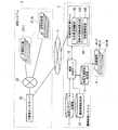
図3は、本実施形態における機器制御システム1の運用例を説明するための図である。同図において、横軸は時刻を示し、縦軸はオフィスに居る社員の人数を示している。同図には、到着時刻予測サーバ14が算出する到着予測時刻に基づいた「○月○日」、「×月×日」、及び「△月△日」のオフィス内に居る社員の人数が、「7:00」から「9:00」までの10分ごとに示されている。このような情報は、例えば、機器制御サーバ15が、到着予測時刻記憶部13に記憶されている到着予測時刻から生成して、表形式の情報として記憶し、空調設備41に対する制御に以下のように用いる。 FIG. 3 is a diagram for explaining an operation example of the device control system 1 in the present embodiment. In the figure, the horizontal axis indicates the time, and the vertical axis indicates the number of employees in the office. In the figure, the number of employees in the office of “○ month ○ day”, “× month × day”, and “△ month Δ day” based on the estimated arrival time calculated by the arrival
図3に示すように、オフィスに出社する人数が予測される場合、「△月△日」において、社員が出社する時刻が「○月○日」や「×月×日」に比べて早いので、機器制御サーバ15は、空調設備41の稼動を開始する時刻を「○月○日」や「×月×日」に比べて早める制御を行うことができる。また、「×月×日」において、出社する社員の人数が「○月○日」や「△月△日」に比べて少ないので、機器制御サーバ15は、空調設備41の稼動レベルを、「○月○日」や「×月×日」に比べて低くする制御を行うことができる。 As shown in Fig. 3, when the number of people who go to the office is predicted, the time when employees go to work in “△ month △ day” is earlier than “○ month ○ day” or “× month × day”. The
また、機器制御システム1は、図3に示すように、社員がオフィスに到着する時刻を予め算出することができるので、社員がオフィスに到着する時刻に応じて、空調設備41に対して予冷運転又は予熱運転をさせる制御をしてもよい。これにより、社員がオフィスに到着した際にオフィスの温度を快適な温度にしておくことができる。また、オフィスに到着する社員の人数が多い場合に予冷運転又は予熱運転をする時間を長くしたり、オフィスに到着する社員の人数が少ない場合に予冷運転又は予熱運転をする時間を短くしたりする制御を行うようにしてもよい。
このように、機器制御システム1は、オフィスに到着する社員の人数を予測し、予測した時刻及び人数に応じて、空調設備41を予め稼動させることができる。Further, as shown in FIG. 3, the device control system 1 can calculate in advance the time at which the employee arrives at the office, so that the
As described above, the device control system 1 can predict the number of employees arriving at the office and operate the
(第2実施形態)
図4は、本発明に係る第2実施形態における機器制御システム3の構成を示す概略ブロック図である。本実施形態における機器制御システム3は、到着時刻予測サーバ34の構成が、第1実施形態の機器制御システム1と異なる。他の構成については、第1実施形態と同じであるので、該当する構成に対して同じ符号を付してその説明を省略する。(Second Embodiment)
FIG. 4 is a schematic block diagram showing the configuration of the device control system 3 in the second embodiment according to the present invention. The device control system 3 in the present embodiment is different from the device control system 1 in the first embodiment in the configuration of the arrival
第2実施形態における到着時刻予測サーバ34は、時刻算出制御部341と、到着予測時刻算出部342とを有している。
時刻算出制御部341は、改札システム2からユーザ通過情報を受信すると、社員がオフィスに到着する到着予測時刻を到着予測時刻算出部342に算出させる制御をする。
到着予測時刻算出部342は、通勤経路記憶部12に記憶されている通勤経路情報と、勤務スケジュール記憶部11に記憶されている個人スケジュール情報と、ユーザ通過情報とに基づいて、社員がオフィスに到着する到着予測時刻を算出する。The arrival
When receiving the user passage information from the
Based on the commuting route information stored in the commuting
図5は、本実施形態における到着時刻予測サーバ34による到着予測時刻算出処理の動作を示すフローチャートである。
到着時刻予測サーバ34において、時刻算出制御部341は、改札システム2に備えられているID管理センタサーバ23からユーザ通過情報を受信すると(ステップS41)、受信したユーザ通過情報に含まれるユーザ識別子に対応する個人スケジュール情報を機器制御サーバ15に要求する(ステップS43)。FIG. 5 is a flowchart showing the operation of the predicted arrival time calculation process by the arrival
In the arrival
時刻算出制御部341は、機器制御サーバ15から個人スケジュール情報を受信すると(ステップS45)、受信した個人スケジュール情報を用いて、社員の予定が社外の予定であるか否かを判定し(ステップS47)し、社外の予定である場合(ステップS47:Yes)、到着予測時刻算出処理を終了する。
一方、社外の予定でない場合(ステップS47:No)、時刻算出制御部341は、受信したユーザ識別子に対応する通勤経路情報を機器制御サーバ15に要求し(ステップS49)、機器制御サーバ15から通勤経路情報を受信する(ステップS51)。When the time
On the other hand, when the schedule is not outside (step S47: No), the time
時刻算出制御部341は、受信した通勤経路情報に含まれるオフィスの最寄り駅と、受信したユーザ通過情報に含まれる駅とが一致しているか否かを判定し(ステップS53)、一致していない場合(ステップS53:No)、到着予測時刻算出処理を終了する。
一方、一致している場合(ステップS53:Yes)、通勤経路情報、及びユーザ通過情報を到着予測時刻算出部342に出力して、到着予測時刻算出部342に到着予測時刻を算出させる。到着予測時刻算出部342は、次式(3)を用いて、社員がオフィスに到着する到着予測時刻を算出する(ステップS55)。The time
On the other hand, if they match (step S53: Yes), the commuting route information and the user passage information are output to the arrival prediction
(到着予測時刻)=(ユーザ通過情報に含まれる時刻)+
(オフィス最寄り駅からオフィスまでの標準的な移動時間) …(3)(Predicted arrival time) = (Time included in user passage information) +
(Standard travel time from the nearest station to the office) (3)
到着予測時刻算出部342は、式(3)により、オフィスの最寄り駅を出場した時刻に基づいて、社員がオフィスに到着する到着予想時刻を算出する。
時刻算出制御部341は、到着予測時刻算出部342が算出した到着予測時刻を示す情報を機器制御サーバ15に出力し(ステップS57)、到着予測時刻算出処理を終了する。The estimated arrival
The time
このように、実施形態における機器制御システム3では、到着時刻予測サーバ34が、オフィスの最寄り駅の自動改札機21を通過した時刻に基づいて、各社員のオフィスへの到着予測時刻を算出するようにしている。
これにより、到着時刻予測サーバ34における計算量を削減することができ、到着時刻予測サーバ34が有する処理能力が低い場合においても、社員がオフィスに到着する到着予測時刻を算出することができる。そして、機器制御サーバ15は、オフィス内に居る社員の数を、社員の到着予測時刻ごとに予測することができ、予測されるオフィス内に居る人数に応じて、空調設備41を予め稼動させることができる。As described above, in the device control system 3 in the embodiment, the arrival
Thereby, the calculation amount in the arrival
なお、上述の第1及び第2実施形態においては、設備機器を空調設備として説明をしたが、これに限定することなく、機器制御システム1は、オフィスに備えられている照明装置や、コンピュータを制御するようにしてもよい。照明装置を制御する場合は、社員がオフィスに到着する時刻に合わせて、照明装置を点灯させるようにして快適性を向上させるようにしてもよい。また、コンピュータを制御する場合は、コンピュータに電源を供給し始めてから利用可能になるまでの起動時間を予め測定しておき、機器制御システム1は、各社員の到着予測時刻より起動時間分早い時刻にコンピュータに対して電源を供給する制御をし、社員が到着に合わせてコンピュータを利用できるようにして、快適性を向上させるようにしてもよい。 In the first and second embodiments described above, the equipment has been described as the air conditioning equipment. However, without being limited to this, the equipment control system 1 includes a lighting device or a computer provided in the office. You may make it control. When controlling the lighting device, comfort may be improved by turning on the lighting device in accordance with the time at which the employee arrives at the office. When the computer is controlled, the startup time from when power is supplied to the computer until it can be used is measured in advance, and the device control system 1 is earlier by the startup time than the estimated arrival time of each employee. The computer may be controlled to supply power to the computer so that employees can use the computer upon arrival to improve comfort.
また、本実施形態において、到着時刻予測サーバ14(34)と、制御機器サーバ15とを異なる装置として説明したが、これに限定することなく、一つの装置として構成するようにしてもよい。
また、本実施形態において、機器制御システム1は、改札システム2から運行情報を受信する構成を説明したが、これに限定することなく、改札システム2と異なるサーバであって、交通機関の遅延や運休などの情報を配信するサーバから運行情報を受信するようにしてもよい。In the present embodiment, the arrival time prediction server 14 (34) and the
Moreover, in this embodiment, although the apparatus control system 1 demonstrated the structure which receives operation information from the
また、本実施形態においては、機器制御システム1は、設備機器を制御する構成について説明したが、社員が到着予測時刻に対してオフィスへの到着が著しく遅れていたり、オフィスの最寄り駅を通過する時刻が著しく遅れていたりする場合に、当該社員のオフィスへの到着が著しく遅れていることを示す注意情報を出力するようにしてもよい。例えば、注意情報の出力として、オフィスの警備をしている警備室や、社員の労務を管理している総務部などのオフィスに備えられているコンピュータにメッセージを送信するようにしてもよいし、社員が所持している携帯電話等に対して現在の状況を連絡するように要求するメッセージを送信するようにしてもよい。 In the present embodiment, the device control system 1 has been described with respect to a configuration for controlling equipment. However, employees arrive significantly late in the office relative to the estimated arrival time or pass through the nearest station of the office. When the time is remarkably delayed, caution information indicating that the arrival of the employee at the office is remarkably delayed may be output. For example, as an output of caution information, a message may be sent to a computer provided in an office such as a security room that guards the office or a general affairs department that manages the labor of employees, You may make it transmit the message which requests | requires contacting the present condition with respect to the mobile telephone etc. which the employee has.
なお、本発明における通勤経路記憶部12、勤務スケジュール記憶部11、到着予測時刻記憶部13、到着時刻予測サーバ14(34)、機器制御サーバ15の機能を実現するためのプログラムをコンピュータ読み取り可能な記録媒体に記録して、この記録媒体に記録されたプログラムをコンピュータシステムに読み込ませ、実行することにより到着予測時刻算出処理と、到着予測時刻に基づいた設備機器41の制御を行ってもよい。なお、ここでいう「コンピュータシステム」とは、OSや周辺機器等のハードウェアを含むものとする。また、「コンピュータシステム」は、ホームページ提供環境(あるいは表示環境)を備えたWWWシステムも含むものとする。また、「コンピュータ読み取り可能な記録媒体」とは、フレキシブルディスク、光磁気ディスク、ROM、CD−ROM等の可搬媒体、コンピュータシステムに内蔵されるハードディスク等の記憶装置のことをいう。更に「コンピュータ読み取り可能な記録媒体」とは、インターネット等のネットワークや電話回線等の通信回線を介してプログラムが送信された場合のサーバやクライアントとなるコンピュータシステム内部の揮発性メモリ(RAM)のように、一定時間プログラムを保持しているものも含むものとする。 It should be noted that the program for realizing the functions of the commuting
また、上記プログラムは、このプログラムを記憶装置等に格納したコンピュータシステムから、伝送媒体を介して、あるいは、伝送媒体中の伝送波により他のコンピュータシステムに伝送されてもよい。ここで、プログラムを伝送する「伝送媒体」は、インターネット等のネットワーク(通信網)や電話回線等の通信回線(通信線)のように情報を伝送する機能を有する媒体のことをいう。また、上記プログラムは、前述した機能の一部を実現するためのものであっても良い。更に、前述した機能をコンピュータシステムにすでに記録されているプログラムとの組み合わせで実現できるもの、いわゆる差分ファイル(差分プログラム)であっても良い。 The program may be transmitted from a computer system storing the program in a storage device or the like to another computer system via a transmission medium or by a transmission wave in the transmission medium. Here, the “transmission medium” for transmitting the program refers to a medium having a function of transmitting information, such as a network (communication network) such as the Internet or a communication line (communication line) such as a telephone line. The program may be for realizing a part of the functions described above. Furthermore, what can implement | achieve the function mentioned above in combination with the program already recorded on the computer system, and what is called a difference file (difference program) may be sufficient.
人が建物に到着する到着予想時刻に基づいて、当該建物に備えられた設備機器を制御するシステムにも適用できる。 The present invention can also be applied to a system that controls equipment installed in a building based on the estimated arrival time when the person arrives at the building.
1,3…機器制御システム、2…改札システム、4…建物、5…ネットワーク、11…勤務スケジュール記憶部、12…通勤経路記憶部、13…到着予測時刻記憶部、14,34…到着時刻予測サーバ、15…機器制御サーバ、21,21−1,21−N…自動改札機、22…サブ・ネットワーク、23…ID管理センタサーバ、41,41−1,41−2,41−M…設備機器(空調設備)、141,341…時刻算出制御部、142,342…到着予測時刻算出部、143…別経路検索部 DESCRIPTION OF SYMBOLS 1,3 ... Equipment control system, 2 ... Ticket gate system, 4 ... Building, 5 ... Network, 11 ... Work schedule memory | storage part, 12 ... Commuting route memory | storage part, 13 ... Arrival prediction time memory | storage part, 14, 34 ... Arrival time prediction Server, 15 ... Device control server, 21, 21-1, 21-N ... Automatic ticket gate, 22 ... Sub-network, 23 ... ID management center server, 41, 41-1, 41-2, 41-M ... Equipment Equipment (air conditioning equipment), 141, 341 ... time calculation control unit, 142, 342 ... arrival prediction time calculation unit, 143 ... alternative route search unit
Claims (4)
Translated fromJapanese前記ユーザが該ユーザに対応する前記移動経路における予め定められた位置を通過した時刻を示す情報と、該ユーザに対応する前記識別子とを含むユーザ通過情報を、前記交通機関における該ユーザの位置を検出する検出装置から受信し、受信したユーザ通過情報に含まれる識別子と一致する識別子を含む移動経路情報を前記移動経路記憶部から読み出し、読み出した移動経路情報に含まれる移動経路と、前記受信したユーザ通過情報に含まれる時刻とから、該ユーザが前記建物に到着する到着予測時刻を算出する到着時刻予測部と、
前記建物に移動する前記ユーザそれぞれに対して算出される前記到着予測時刻に基づいて、前記設備機器を予め稼動させる機器制御部と
を具備することを特徴とする機器制御システム。A travel route storage unit that preliminarily stores travel route information including an identifier for identifying a user and information indicating a travel route using a transportation facility when the user moves to a building equipped with equipment;
User passage information including information indicating the time when the user has passed a predetermined position on the travel route corresponding to the user and the identifier corresponding to the user is obtained as the position of the user in the transportation facility. The travel route information received from the detection device to be detected and including the identifier that matches the identifier included in the received user passage information is read from the travel route storage unit, the travel route included in the read travel route information, and the received An arrival time prediction unit that calculates an estimated arrival time at which the user arrives at the building from the time included in the user passage information;
A device control system comprising: a device control unit that operates the facility device in advance based on the estimated arrival time calculated for each of the users moving to the building.
前記到着時刻予測部は、
前記ユーザごとに、前記スケジュール情報をスケジュール記憶部から読み出し、該ユーザが前記建物に来ることを示している場合に該ユーザの到着予測時刻を算出し、前記建物に来ないことを示している場合に該ユーザの到着予測時刻を算出しない
ことを特徴とする請求項1に記載の機器制御システム。For each of the users, a schedule storage unit that stores in advance schedule information indicating whether or not the user comes to the building is further provided,
The arrival time prediction unit
For each user, when the schedule information is read from the schedule storage unit and indicates that the user is coming to the building, the predicted arrival time of the user is calculated, indicating that the user is not coming to the building 2. The apparatus control system according to claim 1, wherein the predicted arrival time of the user is not calculated.
前記移動経路上で利用される交通機関に生じた遅れや運休を示す運行情報を前記交通機関の運行状況を配信する装置から受信すると、受信した運行情報と、前記ユーザ通過情報と、前記移動経路情報とに基づいて、前記到着予測時刻を算出する
ことを特徴とする請求項1又は請求項2に記載の機器制御システム。The arrival time prediction unit
When operation information indicating delays or suspensions occurring in the transportation system used on the movement route is received from a device that distributes the operation status of the transportation facility, the received operation information, the user passing information, and the movement route The device control system according to claim 1 or 2, wherein the predicted arrival time is calculated based on the information.
前記ユーザが該ユーザに対応する前記移動経路における予め定められた位置を通過した時刻を示す情報と、該ユーザに対応する前記識別子とを含むユーザ通過情報を、前記交通機関における該ユーザの位置を検出する検出装置から受信し、受信したユーザ通過情報に含まれる識別子と一致する識別子を含む移動経路情報を前記移動経路記憶部から読み出し、読み出した移動経路情報に含まれる移動経路と、前記受信したユーザ通過情報に含まれる時刻とから、該ユーザが前記建物に到着する到着予測時刻を算出する到着時刻予測ステップと、
前記建物に移動する前記ユーザそれぞれに対して算出される前記到着予測時刻に基づいて、前記設備機器を予め稼動させる機器制御ステップと
を有することを特徴とする機器制御方法。A travel route storage unit that preliminarily stores travel route information including an identifier for identifying a user and information indicating a travel route using a transportation facility when the user moves to a building having equipment A device control method in a device control system,
User passage information including information indicating the time when the user has passed a predetermined position on the travel route corresponding to the user and the identifier corresponding to the user is obtained as the position of the user in the transportation facility. The travel route information received from the detection device to be detected and including the identifier that matches the identifier included in the received user passage information is read from the travel route storage unit, the travel route included in the read travel route information, and the received An arrival time prediction step for calculating an estimated arrival time at which the user arrives at the building from the time included in the user passage information;
A device control step of operating the facility device in advance based on the predicted arrival time calculated for each of the users moving to the building.
Priority Applications (1)
| Application Number | Priority Date | Filing Date | Title |
|---|---|---|---|
| JP2010255206AJP2012109680A (en) | 2010-11-15 | 2010-11-15 | Equipment control system and equipment control method |
Applications Claiming Priority (1)
| Application Number | Priority Date | Filing Date | Title |
|---|---|---|---|
| JP2010255206AJP2012109680A (en) | 2010-11-15 | 2010-11-15 | Equipment control system and equipment control method |
Publications (1)
| Publication Number | Publication Date |
|---|---|
| JP2012109680Atrue JP2012109680A (en) | 2012-06-07 |
Family
ID=46494859
Family Applications (1)
| Application Number | Title | Priority Date | Filing Date |
|---|---|---|---|
| JP2010255206APendingJP2012109680A (en) | 2010-11-15 | 2010-11-15 | Equipment control system and equipment control method |
Country Status (1)
| Country | Link |
|---|---|
| JP (1) | JP2012109680A (en) |
Cited By (18)
| Publication number | Priority date | Publication date | Assignee | Title |
|---|---|---|---|---|
| JP2014163542A (en)* | 2013-02-21 | 2014-09-08 | Fujitsu Ltd | Control device, control method and control program |
| WO2016067719A1 (en)* | 2014-10-29 | 2016-05-06 | 株式会社日立製作所 | Air conditioning control method and system |
| EP3091300A4 (en)* | 2015-03-27 | 2017-04-26 | Mitsubishi Electric Corporation | Terminal apparatus, air conditioner, and wearable terminal |
| US9900174B2 (en) | 2015-03-06 | 2018-02-20 | Honeywell International Inc. | Multi-user geofencing for building automation |
| US9967391B2 (en) | 2015-03-25 | 2018-05-08 | Honeywell International Inc. | Geo-fencing in a building automation system |
| US10057110B2 (en) | 2015-11-06 | 2018-08-21 | Honeywell International Inc. | Site management system with dynamic site threat level based on geo-location data |
| US10271284B2 (en) | 2015-11-11 | 2019-04-23 | Honeywell International Inc. | Methods and systems for performing geofencing with reduced power consumption |
| US10317102B2 (en) | 2017-04-18 | 2019-06-11 | Ademco Inc. | Geofencing for thermostatic control |
| JP2019145998A (en)* | 2018-02-20 | 2019-08-29 | 日本電気株式会社 | Data collection device and base station |
| US10516965B2 (en) | 2015-11-11 | 2019-12-24 | Ademco Inc. | HVAC control using geofencing |
| US10605472B2 (en) | 2016-02-19 | 2020-03-31 | Ademco Inc. | Multiple adaptive geo-fences for a building |
| US10802459B2 (en) | 2015-04-27 | 2020-10-13 | Ademco Inc. | Geo-fencing with advanced intelligent recovery |
| US10802469B2 (en) | 2015-04-27 | 2020-10-13 | Ademco Inc. | Geo-fencing with diagnostic feature |
| WO2020255337A1 (en)* | 2019-06-20 | 2020-12-24 | 三菱電機ビルテクノサービス株式会社 | Number-of-people prediction device, equipment management system, and number-of-people prediction method |
| JP2022032347A (en)* | 2020-08-11 | 2022-02-25 | トヨタ自動車株式会社 | Air conditioning control system and air conditioning control method |
| WO2022162932A1 (en)* | 2021-02-01 | 2022-08-04 | 三菱電機株式会社 | Air conditioning control system, control device, air conditioning control method, and program |
| WO2022185399A1 (en)* | 2021-03-02 | 2022-09-09 | 三菱電機株式会社 | Air conditioning system and learning device |
| CN116045495A (en)* | 2023-01-16 | 2023-05-02 | 珠海格力电器股份有限公司 | Air conditioner control method, air conditioner control device and air conditioner control system |
- 2010
- 2010-11-15JPJP2010255206Apatent/JP2012109680A/enactivePending
Cited By (26)
| Publication number | Priority date | Publication date | Assignee | Title |
|---|---|---|---|---|
| JP2014163542A (en)* | 2013-02-21 | 2014-09-08 | Fujitsu Ltd | Control device, control method and control program |
| WO2016067719A1 (en)* | 2014-10-29 | 2016-05-06 | 株式会社日立製作所 | Air conditioning control method and system |
| US9900174B2 (en) | 2015-03-06 | 2018-02-20 | Honeywell International Inc. | Multi-user geofencing for building automation |
| US10462283B2 (en) | 2015-03-25 | 2019-10-29 | Ademco Inc. | Geo-fencing in a building automation system |
| US9967391B2 (en) | 2015-03-25 | 2018-05-08 | Honeywell International Inc. | Geo-fencing in a building automation system |
| US10674004B2 (en) | 2015-03-25 | 2020-06-02 | Ademco Inc. | Geo-fencing in a building automation system |
| US10571144B2 (en) | 2015-03-27 | 2020-02-25 | Mitsubishi Electric Corporation | Terminal device, air conditioner, and wearable terminal |
| EP3091300A4 (en)* | 2015-03-27 | 2017-04-26 | Mitsubishi Electric Corporation | Terminal apparatus, air conditioner, and wearable terminal |
| US10802469B2 (en) | 2015-04-27 | 2020-10-13 | Ademco Inc. | Geo-fencing with diagnostic feature |
| US10802459B2 (en) | 2015-04-27 | 2020-10-13 | Ademco Inc. | Geo-fencing with advanced intelligent recovery |
| US10057110B2 (en) | 2015-11-06 | 2018-08-21 | Honeywell International Inc. | Site management system with dynamic site threat level based on geo-location data |
| US10271284B2 (en) | 2015-11-11 | 2019-04-23 | Honeywell International Inc. | Methods and systems for performing geofencing with reduced power consumption |
| US10516965B2 (en) | 2015-11-11 | 2019-12-24 | Ademco Inc. | HVAC control using geofencing |
| US10605472B2 (en) | 2016-02-19 | 2020-03-31 | Ademco Inc. | Multiple adaptive geo-fences for a building |
| US10317102B2 (en) | 2017-04-18 | 2019-06-11 | Ademco Inc. | Geofencing for thermostatic control |
| JP2019145998A (en)* | 2018-02-20 | 2019-08-29 | 日本電気株式会社 | Data collection device and base station |
| JP7052400B2 (en) | 2018-02-20 | 2022-04-12 | 日本電気株式会社 | Data acquisition device and base station |
| WO2020255337A1 (en)* | 2019-06-20 | 2020-12-24 | 三菱電機ビルテクノサービス株式会社 | Number-of-people prediction device, equipment management system, and number-of-people prediction method |
| JP6818937B1 (en)* | 2019-06-20 | 2021-01-27 | 三菱電機ビルテクノサービス株式会社 | Location number prediction device, equipment management system, and location number prediction method |
| JP2022032347A (en)* | 2020-08-11 | 2022-02-25 | トヨタ自動車株式会社 | Air conditioning control system and air conditioning control method |
| WO2022162932A1 (en)* | 2021-02-01 | 2022-08-04 | 三菱電機株式会社 | Air conditioning control system, control device, air conditioning control method, and program |
| JPWO2022162932A1 (en)* | 2021-02-01 | 2022-08-04 | ||
| JP7374355B2 (en) | 2021-02-01 | 2023-11-06 | 三菱電機株式会社 | Air conditioning control system, control device, air conditioning control method and program |
| WO2022185399A1 (en)* | 2021-03-02 | 2022-09-09 | 三菱電機株式会社 | Air conditioning system and learning device |
| JP7483122B2 (en) | 2021-03-02 | 2024-05-14 | 三菱電機株式会社 | Air conditioning system and learning device |
| CN116045495A (en)* | 2023-01-16 | 2023-05-02 | 珠海格力电器股份有限公司 | Air conditioner control method, air conditioner control device and air conditioner control system |
Similar Documents
| Publication | Publication Date | Title |
|---|---|---|
| JP2012109680A (en) | Equipment control system and equipment control method | |
| US11803930B2 (en) | Timetable modification device and automatic train control system | |
| CN1835017B (en) | Security system and site management method | |
| JP2024023564A (en) | Timetable creation device, timetable creation method, and automatic train control system | |
| KR102424689B1 (en) | Method and apparatus of heating ventilation air conditioning for controlling start | |
| US7734383B2 (en) | Method and apparatus for planning the movement of trains using dynamic analysis | |
| US9117252B2 (en) | Information processing device, terminal, server, and method for data transfer | |
| JP2014091480A (en) | Operation arrangement device and method | |
| JP6085508B2 (en) | Air conditioning set temperature calculation device, air conditioning set temperature calculation program, and air conditioning set temperature calculation method | |
| KR102317461B1 (en) | Intelligent parking guidance service system and method by deep learning based parking lot usage analysis | |
| CN113887953A (en) | Intelligent scheduling management method and device, computer equipment and storage medium | |
| JP2015057588A (en) | Delay notification device | |
| KR101626819B1 (en) | Remote maintenance server, total maintenance system including the remote maintenance server and method thereof | |
| KR20220085226A (en) | Internet-of-thing based floating population analysis system and method thereof | |
| JP2009113601A (en) | Guidance information distribution system | |
| JP2008174145A (en) | Driving arrangement support system | |
| Zhao et al. | When autonomous vehicles meet accidents: A DT-enabled post-accident maintenance scheme | |
| JP2007199900A (en) | Information distribution system | |
| JP2022037515A (en) | Operation association apparatus and operation association support method | |
| JP2021038948A (en) | System and management equipment | |
| JP5380358B2 (en) | Operation restart time prediction method and apparatus | |
| JP2005121575A (en) | Movement schedule management system, movement schedule management method, and movement schedule management program | |
| JP2005038317A (en) | System for updating bus schedule | |
| KR101590821B1 (en) | Location-based public safety system using wifi tag for passenger for public transportation and operating method thereof | |
| Niu et al. | An approach to optimize the departure times of transit vehicles with strict capacity constraints |