JP2012104345A - Lighting fixture - Google Patents
Lighting fixtureDownload PDFInfo
- Publication number
- JP2012104345A JP2012104345AJP2010251244AJP2010251244AJP2012104345AJP 2012104345 AJP2012104345 AJP 2012104345AJP 2010251244 AJP2010251244 AJP 2010251244AJP 2010251244 AJP2010251244 AJP 2010251244AJP 2012104345 AJP2012104345 AJP 2012104345A
- Authority
- JP
- Japan
- Prior art keywords
- optical axis
- lighting fixture
- led
- light
- wall surface
- Prior art date
- Legal status (The legal status is an assumption and is not a legal conclusion. Google has not performed a legal analysis and makes no representation as to the accuracy of the status listed.)
- Granted
Links
Images


Landscapes
- Securing Globes, Refractors, Reflectors Or The Like (AREA)
- Non-Portable Lighting Devices Or Systems Thereof (AREA)
Abstract
Translated fromJapaneseDescription
Translated fromJapanese本発明は、駅のホーム等の上方に設けて、ホームおよび壁面に光を照射する照明器具に関するものである。 The present invention relates to a lighting fixture that is provided above a platform of a station and irradiates light on the platform and a wall surface.
従来より、天井面等に取り付けて主に下方を照明するために、細長い照明器具が用いられている(例えば、特許文献1参照)。
図7に示すように、特許文献1に記載の照明器具100では、軸方向に細長く下方に開口した矩形箱状の筐体101を有し、筐体101の内部に、軸方向に長いLED蛍光管102と、このLED蛍光管102の光を下方へ反射する反射板103を有する。
LED蛍光管102は、軸方向に細長い板状のプリント基板104にLED105を実装して形成されたLED発光体106を、放熱板108を介して一部開口した略円管状の半透明のカバー体107内部に取り付けて形成される。2. Description of the Related Art Conventionally, a long and narrow lighting fixture has been used to attach to a ceiling surface or the like and mainly illuminate a lower part (see, for example, Patent Document 1).
As shown in FIG. 7, the
The LED
これにより、LED蛍光管102から照射される光を、広く拡散させて、照度を落とすことなく効率的に下方へ照射する。 Thereby, the light irradiated from the LED
ところで、照明器具を設置する場所に対応して、光の照射範囲を限定したい場合がある。
図8に示すように、光源にLEDユニット111を用いて所望の範囲を照明する照明器具110においては、LEDユニット111の照射方向前方の左右両側に反射板112,113を設けて照射範囲を規制している。LEDユニット111の光軸CBは、照射方向である鉛直下方に向けられており、反射板112,113は光軸CBに対して対称に設けられている。
これにより、横方向に発せられる光を反射板112,113により反射して、所望の方向(下方)へ効率よく光を照射している。By the way, there is a case where it is desired to limit the light irradiation range corresponding to the place where the lighting fixture is installed.
As shown in FIG. 8, in the
Thereby, the light emitted in the lateral direction is reflected by the
しかしながら、前述した照明器具110のように、光源にLEDユニット111を用いる場合には、蛍光灯を用いる場合に比して、もともと横方向への広がりが少ない上に、反射板112,113によって横方向の光がさらに遮光されてしまうので、例えば駅のホーム等の照明においては、ホーム後方の壁面における垂直面照度が不足して、時刻表や広告等が見えにくくなるという問題があった。 However, when the
本発明は、従来の問題を解決するためになされたもので、壁面に取り付けられた広告等が見やすく、かつ壁面と反対側にいる人へのグレアを抑えた照明器具を提供することを目的とする。 The present invention has been made to solve the conventional problems, and it is an object of the present invention to provide a lighting apparatus that is easy to see advertisements and the like attached to a wall surface and that suppresses glare to a person on the opposite side of the wall surface. To do.
本発明の照明器具は、光軸が鉛直下方より所定角度傾いて配されるLEDと、前記LEDの光軸が傾いている側とは反対側の側方に設けられ、前記LEDからの光を遮断し、かつ、前記LEDの光軸側に光を反射する反光軸側反射板と、を有するものである。 The lighting fixture of the present invention is provided on the side opposite to the side where the optical axis of the LED is inclined and the LED where the optical axis is inclined at a predetermined angle from below vertically, and the light from the LED is transmitted. And an anti-optical axis side reflecting plate that blocks light and reflects light toward the optical axis side of the LED.
また、本発明の照明器具は、前記反光軸側反射板の遮光角θ1が、
θ1≧tan−1((h0−h1)/d1)、
h0:照明器具の設置高さ、
h1:視点の高さ、
d1:照明器具と視点の水平距離、
であるものである。In the lighting fixture of the present invention, the light-shielding angle θ1 of the anti-optical axis side reflector is
θ1 ≧ tan−1 ((h0−h1) / d1),
h0: installation height of the lighting fixture,
h1: Height of viewpoint,
d1: Horizontal distance between the lighting fixture and the viewpoint,
It is what is.
また、本発明の照明器具は、前記LEDの光軸側の側方に光軸側反射板を備え、その遮光角が前記反光軸側反射板の遮光角よりも小さいものである。 Moreover, the lighting fixture of this invention equips the side by the side of the optical axis of said LED with the optical-axis side reflecting plate, The light-blocking angle is a thing smaller than the light-blocking angle of the said anti-optical-axis side reflecting plate.
さらに、本発明の照明器具は、前記光軸側反射板の遮光角θ2が、
θ2≦tan−1((h0−h2)/d2)、
h0:照明器具の設置高さ、
h2:広告等の上端の高さ、
d2:照明器具と広告等の水平距離、
であるものである。Furthermore, in the lighting fixture of the present invention, the light shielding angle θ2 of the optical axis side reflector is
θ2 ≦ tan−1 ((h0−h2) / d2),
h0: installation height of the lighting fixture,
h2: the height of the top edge of the advertisement, etc.
d2: Horizontal distance between lighting fixtures and advertisements,
It is what is.
本発明は、LEDの光軸を傾けているので、光軸を傾けた側の壁面の鉛直面照度が高くなり、壁面に掲げられた広告等が見えやすくなる。また、光軸と反対側に反射板を設けたので、反射板によって遮光され、光軸と反対側にいる人へのグレアを抑えることができるという効果を有する照明器具を提供できる。 In the present invention, since the optical axis of the LED is inclined, the vertical surface illuminance on the wall surface on which the optical axis is inclined is increased, and advertisements and the like placed on the wall surface can be easily seen. Further, since the reflecting plate is provided on the side opposite to the optical axis, it is possible to provide a lighting apparatus that has an effect of being shielded by the reflecting plate and suppressing glare to a person on the side opposite to the optical axis.
以下、本発明に係る実施形態の照明器具について、図面を用いて説明する。
図1および図2に示すように、本発明に係る実施形態の照明器具10は、駅(図3参照)のホーム13等の天井面11にとりつけられて、ホーム13や、線路14やホーム13後方(線路14と反対側)の壁面12を照明するのに用いることができる。Hereinafter, the lighting fixture of embodiment which concerns on this invention is demonstrated using drawing.
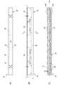
As shown in FIG. 1 and FIG. 2, the
照明器具10は、例えばホーム13に沿って長い器具本体20を有しており、直接天井面11に取り付けられたり、給配電のための電路であるレースウェイ21を介して天井面11に取り付けられる。
器具本体20は、下方が開口(開口部21)した矩形箱状を呈しており、天板22がボルト・ナット23により天井面11等に取り付けられる。天板22の下面には電源装置34が取り付けられており、器具本体20の内部に収容される。The
The instrument
器具本体20は、壁面12側の側板24と、側板24に対向する線路側の側板25を有する。両側板24,25間には取付板26が傾斜して取り付けられており、取付板26にはLEDユニット(LED)30が取り付けられている。
取付板26の傾斜に対応して、壁面側の側板24よりも、線路側の側板25の方が長く下方まで設けられている。The instrument
Corresponding to the inclination of the
LEDユニット30は、器具本体20の長手方向に沿って複数個(ここでは、例えば8個)設けられている。各LEDユニット30は、矩形板状の基板31の上に複数個(ここでは、例えば6個)のLEDチップ32が取り付けられている。また、LEDチップ32の前方には拡散材入りのパネル33が設けられている。 A plurality of (for example, eight)
LEDユニット30は取付板26の下面に取り付けられている。このため、LEDユニット30の光軸L1は、取付板26に直交する方向であり、壁面側の側板24側に傾いている。以後、鉛直方向に対して光軸L1がある側を光軸側または壁面側といい、光軸L1が無い側を反光軸側または線路側という。 The
器具本体20内部における取付板26の下側には、光を遮断するとともに、光を光軸L1方向へ反射する反射板35が取り付けられている。反射板35は、鉛直方向に対して光軸L1がある側に設けられて光を線路側に反射する光軸側反射板351と、鉛直方向に対して光軸L1が無い側に設けられて光を壁面側に反射する反光軸側反射板352とを有する。 A
図3は、本発明適用のモデルである駅の断面構成図である。
図3に示すように、駅における各部の必要照度は、ホーム13では、Eh≧200(lx)、線路14では、Er≧20(lx)、ホーム13後方の壁面12では、Ev≧100(lx)に設定されている。また、各部における寸法は、図3に示す通りである。FIG. 3 is a sectional configuration diagram of a station which is a model to which the present invention is applied.
As shown in FIG. 3, the required illuminance of each part in the station is Eh ≧ 200 (lx) at the
図4には、光軸L1の角度θ(図2参照)を5°刻みで30°まで変化させた場合の、各部の計算照度を示してある。
図4に示すように、光軸L1の角度θを大きくするほど、壁面12の鉛直面照度が大きくなるが、ホーム13および線路14の水平面照度が小さくなる傾向が見られる。また、上述した各部位の必要照度を満足する角度θは、壁面12の鉛直照度が100(lx)を超える15°となる。このとき、ホーム13および線路14における必要照度をも満足する。FIG. 4 shows the calculated illuminance of each part when the angle θ (see FIG. 2) of the optical axis L1 is changed to 30 ° in increments of 5 °.
As shown in FIG. 4, as the angle θ of the optical axis L <b> 1 is increased, the vertical illuminance of the
図5に示すように、上述したモデルの駅における反光軸側反射板352による遮光角θ1は、線路14を走る電車の運転士の視点と照明器具10との位置関係から、
θ1≧tan−1((h0−h1)/d1)、
h0:照明器具の設置高さ、
h1:視点の高さ、
d1:照明器具と視点の水平距離、
各変数に図5に示す数値を代入すると、
θ1≧tan((2.9−1.4)/1.8)
≧40°
より、反光軸側反射板352の遮光角θ1が40°以上になるように、線路側の側板25の高さを設定する。As shown in FIG. 5, the light blocking angle θ1 by the anti-optical
θ1 ≧ tan−1 ((h0−h1) / d1),
h0: installation height of the lighting fixture,
h1: Height of viewpoint,
d1: Horizontal distance between the lighting fixture and the viewpoint,
Substituting the values shown in Fig. 5 for each variable,
θ1 ≧ tan ((2.9−1.4) /1.8)
≧ 40 °
Accordingly, the height of the
図6に示すように、光軸側反射板351による遮光角θ2は、反光軸側反射板352の遮光角θ1(図5参照)よりも小さいものであり、
θ2≦tan−1((h0−h2)/d2)、
h0:照明器具の設置高さ、
h2:広告等の上端の高さ、
d2:照明器具と広告等の水平距離、
各変数に図6に示す数値を代入すると、
θ2≦tan((2.9−2.4)/3)
≦10°
より、光軸側反射板352の遮光角θ2が10°以下になるように、壁面側の側板24の高さを設定する。As shown in FIG. 6, the light blocking angle θ2 by the optical axis
θ2 ≦ tan−1 ((h0−h2) / d2),
h0: installation height of the lighting fixture,
h2: the height of the top edge of the advertisement, etc.
d2: Horizontal distance between lighting fixtures and advertisements,
Substituting the values shown in Fig. 6 for each variable,
θ2 ≦ tan ((2.9-2.4) / 3)
≦ 10 °
Thus, the height of the
以上、説明した本発明に係る照明器具10は、LEDユニット30の光軸L1を傾けているので、鉛直方向よりも光軸L1を傾けた側の壁面12の鉛直面照度が高くなり、壁面12に掲げられた広告121等が見やすくなる。すなわち、光軸L1を15°傾けることにより、壁面12の鉛直面照度として100(lx)が確保できるので、広告121や時刻表等が見やすくなる。
また、反射板35によって遮光されるので、鉛直方向よりも光軸L1と反対側にいる人へのグレアを抑えることができる。As described above, since the
Further, since the light is shielded by the reflecting
また、反光軸側反射板352の遮光角θ1を、照明器具10と視点の位置関係から、LEDユニット30が直接見えなくなる必要最小限の遮光角よりも大きくするので、より確実にグレアを抑えることができる。すなわち、線路14側の反光軸側反射板352の遮光角θ1を40°以上に設定したことにより、電車の運転士に対するグレアを確実に抑えることができる。 Further, since the light shielding angle θ1 of the counter-optical axis
また、鉛直方向よりも光軸L1を傾けた側の光軸側反射板351を設けたので、天井面11に漏れる光を光軸側反射板351で下方向に反射することにより、効率よくホーム13を照明することができる。また、青色LEDと黄色蛍光体を組み合わせた白色LEDを用いた場合に、特有の横方向へ出る黄色の光のスジが、天井面等に現れることを防ぐことができる。 In addition, since the optical axis
さらに、光軸側反射板351の遮光角θ2を、照明器具10と広告121等の位置関係から、LEDユニット30からの光が遮られないための遮光角の最大値よりも小さくするので、広告121等の見えやすさを損なわずに、効率よくホーム13を照明することができる。すなわち、壁面12側の光軸側反射板351の遮光角θ2を、10°以下に設定したことにより、広告121や時刻表等の見やすさを損なわずに、効率よくホーム13を照明することができる。 Further, the light shielding angle θ2 of the optical axis
なお、本発明の照明器具は、前述した実施形態に限定されるものでなく、適宜な変形,改良等が可能である。
例えば、前述した実施形態においては、駅のホーム13に取り付ける照明器具を例示したが、この他、マンションの開放廊下等、一方に視対象となる壁面があり、他方が解放されているような空間に広く適用可能である。In addition, the lighting fixture of this invention is not limited to embodiment mentioned above, A suitable deformation | transformation, improvement, etc. are possible.
For example, in the above-described embodiment, the lighting apparatus attached to the
10 照明器具
32 LEDチップ(LED)
351 光軸側反射板
352 反光軸側反射板
L1 光軸
θ1 反光軸側反射板の遮光角
θ2 光軸側反射板の遮光角10
351 Optical axis
Claims (4)
Translated fromJapanese前記LEDの光軸が傾いている側とは反対側の側方に設けられ、前記LEDからの光を遮断し、かつ、前記LEDの光軸側に光を反射する反光軸側反射板と、を有する照明器具。LEDs whose optical axis is inclined at a predetermined angle from vertically below;
An anti-optical axis side reflector that is provided on a side opposite to the side where the optical axis of the LED is inclined, blocks light from the LED, and reflects light toward the optical axis of the LED; A lighting fixture having.
前記反光軸側反射板の遮光角θ1が、
θ1≧tan−1((h0−h1)/d1)、
h0:照明器具の設置高さ、
h1:視点の高さ、
d1:照明器具と視点の水平距離、
である照明器具。The lighting fixture according to claim 1,
The light blocking angle θ1 of the counter-optical axis side reflector is
θ1 ≧ tan−1 ((h0−h1) / d1),
h0: installation height of the lighting fixture,
h1: Height of viewpoint,
d1: Horizontal distance between the lighting fixture and the viewpoint,
Is a lighting fixture.
前記LEDの光軸側の側方に光軸側反射板を備え、その遮光角が前記反光軸側反射板の遮光角よりも小さい照明器具。The lighting fixture according to claim 1 or 2,
An illumination fixture comprising an optical axis side reflector on a side of the LED on the optical axis side and having a light shielding angle smaller than that of the counter optical axis side reflector.
前記光軸側反射板の遮光角θ2が、
θ2≦tan−1((h0−h2)/d2)、
h0:照明器具の設置高さ、
h2:広告等の上端の高さ、
d2:照明器具と広告等の水平距離、
である照明器具。The lighting fixture according to claim 3,
The light blocking angle θ2 of the optical axis side reflecting plate is
θ2 ≦ tan−1 ((h0−h2) / d2),
h0: installation height of the lighting fixture,
h2: the height of the top edge of the advertisement, etc.
d2: Horizontal distance between lighting fixtures and advertisements,
Is a lighting fixture.
Priority Applications (1)
| Application Number | Priority Date | Filing Date | Title |
|---|---|---|---|
| JP2010251244AJP5736540B2 (en) | 2010-11-09 | 2010-11-09 | lighting equipment |
Applications Claiming Priority (1)
| Application Number | Priority Date | Filing Date | Title |
|---|---|---|---|
| JP2010251244AJP5736540B2 (en) | 2010-11-09 | 2010-11-09 | lighting equipment |
Publications (2)
| Publication Number | Publication Date |
|---|---|
| JP2012104345Atrue JP2012104345A (en) | 2012-05-31 |
| JP5736540B2 JP5736540B2 (en) | 2015-06-17 |
Family
ID=46394503
Family Applications (1)
| Application Number | Title | Priority Date | Filing Date |
|---|---|---|---|
| JP2010251244AActiveJP5736540B2 (en) | 2010-11-09 | 2010-11-09 | lighting equipment |
Country Status (1)
| Country | Link |
|---|---|
| JP (1) | JP5736540B2 (en) |
Cited By (4)
| Publication number | Priority date | Publication date | Assignee | Title |
|---|---|---|---|---|
| JP2014072142A (en)* | 2012-10-01 | 2014-04-21 | Panasonic Corp | Lighting apparatus |
| JP2015153712A (en)* | 2014-02-19 | 2015-08-24 | 三菱電機株式会社 | Control member and lighting device equipped with control member |
| JP2016126910A (en)* | 2014-12-26 | 2016-07-11 | 株式会社Lixil | Lighting device |
| CN108139043A (en)* | 2015-08-20 | 2018-06-08 | 斯乔尔基娜·耐大丽阿·奥列格夫娜 | Method of producing light output and slender cornice light implementing the method |
Citations (4)
| Publication number | Priority date | Publication date | Assignee | Title |
|---|---|---|---|---|
| JPH01122502A (en)* | 1987-11-06 | 1989-05-15 | Matsushita Electric Ind Co Ltd | Wall lighting method |
| JP2001250403A (en)* | 2000-03-07 | 2001-09-14 | Matsushita Electric Works Ltd | Wall mounted lighting fixture |
| JP2002289028A (en)* | 2001-03-28 | 2002-10-04 | Mitsubishi Electric Corp | Lighting equipment |
| JP2008123852A (en)* | 2006-11-13 | 2008-05-29 | Toshiba Lighting & Technology Corp | Lighting device |
- 2010
- 2010-11-09JPJP2010251244Apatent/JP5736540B2/enactiveActive
Patent Citations (4)
| Publication number | Priority date | Publication date | Assignee | Title |
|---|---|---|---|---|
| JPH01122502A (en)* | 1987-11-06 | 1989-05-15 | Matsushita Electric Ind Co Ltd | Wall lighting method |
| JP2001250403A (en)* | 2000-03-07 | 2001-09-14 | Matsushita Electric Works Ltd | Wall mounted lighting fixture |
| JP2002289028A (en)* | 2001-03-28 | 2002-10-04 | Mitsubishi Electric Corp | Lighting equipment |
| JP2008123852A (en)* | 2006-11-13 | 2008-05-29 | Toshiba Lighting & Technology Corp | Lighting device |
Cited By (5)
| Publication number | Priority date | Publication date | Assignee | Title |
|---|---|---|---|---|
| JP2014072142A (en)* | 2012-10-01 | 2014-04-21 | Panasonic Corp | Lighting apparatus |
| JP2015153712A (en)* | 2014-02-19 | 2015-08-24 | 三菱電機株式会社 | Control member and lighting device equipped with control member |
| JP2016126910A (en)* | 2014-12-26 | 2016-07-11 | 株式会社Lixil | Lighting device |
| CN108139043A (en)* | 2015-08-20 | 2018-06-08 | 斯乔尔基娜·耐大丽阿·奥列格夫娜 | Method of producing light output and slender cornice light implementing the method |
| EP3339718A4 (en)* | 2015-08-20 | 2019-01-16 | Sterkina, Natalia Olegovna | Luminous flux creation method and extended cornice lamp for implementing same |
Also Published As
| Publication number | Publication date |
|---|---|
| JP5736540B2 (en) | 2015-06-17 |
Similar Documents
| Publication | Publication Date | Title |
|---|---|---|
| US20130120991A1 (en) | Lighting module for illuminating traffic routes, and traffic route luminaire | |
| JP6539665B2 (en) | Sports lighting equipment | |
| JP5921649B2 (en) | Lighting device | |
| CN102654253A (en) | Lighting fixture with selected light distribution pattern | |
| JP2009026481A (en) | Lighting fixture | |
| JP5736540B2 (en) | lighting equipment | |
| JP5895187B2 (en) | LED lighting fixtures | |
| JP6544679B2 (en) | Light source unit and lighting apparatus using the same | |
| JP6902704B2 (en) | Road lighting | |
| CN102168814B (en) | Lighting device | |
| JP4882795B2 (en) | Security light | |
| JP5277939B2 (en) | lighting equipment | |
| JP6720593B2 (en) | Road lighting lens and road lighting equipment | |
| JP5635325B2 (en) | lighting equipment | |
| JP5966674B2 (en) | Vehicle lighting | |
| KR101274145B1 (en) | Lighting apparatus for blackboard | |
| JP5241018B2 (en) | lighting equipment | |
| JP5505238B2 (en) | Reflector, LED module, and lighting fixture | |
| JP2012181950A (en) | Lighting fixture | |
| JP2014127380A (en) | Illumination device | |
| GB2584013A (en) | Pathway lighting bollard | |
| JP2014099306A (en) | Led lighting device | |
| JP6418448B2 (en) | Lighting device | |
| JP2011187244A (en) | Led unit, and horizontal light | |
| JP6028412B2 (en) | Light source unit and lighting apparatus |
Legal Events
| Date | Code | Title | Description |
|---|---|---|---|
| A621 | Written request for application examination | Free format text:JAPANESE INTERMEDIATE CODE: A621 Effective date:20131021 | |
| RD04 | Notification of resignation of power of attorney | Free format text:JAPANESE INTERMEDIATE CODE: A7424 Effective date:20131225 | |
| A977 | Report on retrieval | Free format text:JAPANESE INTERMEDIATE CODE: A971007 Effective date:20140528 | |
| A131 | Notification of reasons for refusal | Free format text:JAPANESE INTERMEDIATE CODE: A131 Effective date:20140624 | |
| A521 | Written amendment | Free format text:JAPANESE INTERMEDIATE CODE: A523 Effective date:20140819 | |
| A711 | Notification of change in applicant | Free format text:JAPANESE INTERMEDIATE CODE: A711 Effective date:20141007 | |
| TRDD | Decision of grant or rejection written | ||
| A01 | Written decision to grant a patent or to grant a registration (utility model) | Free format text:JAPANESE INTERMEDIATE CODE: A01 Effective date:20150106 | |
| RD02 | Notification of acceptance of power of attorney | Free format text:JAPANESE INTERMEDIATE CODE: A7422 Effective date:20150119 | |
| A61 | First payment of annual fees (during grant procedure) | Free format text:JAPANESE INTERMEDIATE CODE: A61 Effective date:20150204 | |
| R151 | Written notification of patent or utility model registration | Ref document number:5736540 Country of ref document:JP Free format text:JAPANESE INTERMEDIATE CODE: R151 |