JP2012103802A - Information processor and electronic control unit - Google Patents
Information processor and electronic control unitDownload PDFInfo
- Publication number
- JP2012103802A JP2012103802AJP2010250100AJP2010250100AJP2012103802AJP 2012103802 AJP2012103802 AJP 2012103802AJP 2010250100 AJP2010250100 AJP 2010250100AJP 2010250100 AJP2010250100 AJP 2010250100AJP 2012103802 AJP2012103802 AJP 2012103802A
- Authority
- JP
- Japan
- Prior art keywords
- task
- execution
- time
- initial processing
- initial
- Prior art date
- Legal status (The legal status is an assumption and is not a legal conclusion. Google has not performed a legal analysis and makes no representation as to the accuracy of the status listed.)
- Pending
Links
Images


Landscapes
- Debugging And Monitoring (AREA)
Abstract
Translated fromJapaneseDescription
Translated fromJapanese本発明は、車両に搭載される情報処理装置に関し、初期処理の後にタスクを実行する情報処理装置に関する。 The present invention relates to an information processing apparatus mounted on a vehicle, and relates to an information processing apparatus that executes a task after initial processing.
車載されているECU(Electronic Control Unit)は、動作を保証するため起動時と終了時に特定の処理を行うようになっている。ECUは、例えば、IG(イグニッション)=ONにより初期処理(ソフトリセット&プライマリチェック)を開始し、その後、通常処理を開始してIG=OFFになるまでは通常処理を実行し、IG=OFFにより終了処理を開始し、それが終わるとリレーをオフにする。したがって、初期処理に相当するプライマリチェックが終了しないと、通常処理が開始されないため、次のような不都合が生じうる。 A vehicle-mounted ECU (Electronic Control Unit) performs specific processing at the time of start and end in order to guarantee the operation. For example, the ECU starts an initial process (soft reset & primary check) with IG (ignition) = ON, and then starts normal processing until IG = OFF, and executes normal processing. End processing is started, and when it is finished, the relay is turned off. Therefore, since the normal process is not started unless the primary check corresponding to the initial process is completed, the following inconvenience may occur.
図1は、プライマリチェックと通常処理のタイミングチャート図の一例を示す図である。上段は不都合が生じない場合を、下段は不都合が生じる場合をそれぞれ示す。
IG=ONからIG=OFFになると通常処理が終了し、ECUは終了処理を開始する。終了処理の途中に、IG=ONになると、ECUは終了処理を停止せず継続する。
終了処理が終了すると、ECUはプライマリチェックを開始し、プライマリチェックが終了すると通常処理を開始する。FIG. 1 is a diagram illustrating an example of a timing chart of primary check and normal processing. The upper part shows a case where no inconvenience occurs, and the lower part shows a case where inconvenience occurs.
When IG = ON is changed to IG = OFF, the normal process ends, and the ECU starts the end process. If IG = ON during the termination process, the ECU continues without terminating the termination process.
When the end process ends, the ECU starts the primary check, and when the primary check ends, the ECU starts the normal process.
このため、下段のように、終了処理が終了するまでに長い時間がかかると、プライマリチェックが開始される時間が遅くなる。終了処理の内容は、IG=ONからIG=OFFになった時のECUの処理対象の状態(アクチュエータやECUのハード)により変わるため、終了処理が終了するまでの時間は不定である。 For this reason, if it takes a long time to finish the termination process as shown in the lower part, the time for starting the primary check is delayed. Since the content of the end process varies depending on the state of the processing target of the ECU when IG = ON is changed from IG = OFF (actuator or ECU hardware), the time until the end process ends is indefinite.
プライマリチェックが終了までの時間はほぼ同じであるが、終了処理が長くかかると、プライマリチェックが終了する時刻もずれ込み通常処理の開始時刻が遅くなる。しかしながら、例えば、機能統合によりCANゲートウェイの機能がECUに統合された場合、他のECUがCAN通信するには、機能統合されたECUのプライマリチェックが終了することが必要になる。図では、通常処理がCANゲートウェイの機能を制御するアプリである。 The time until the end of the primary check is almost the same, but if the end process takes a long time, the time at which the primary check ends is shifted and the start time of the normal process is delayed. However, for example, when the function of the CAN gateway is integrated into the ECU by function integration, in order for another ECU to perform CAN communication, it is necessary to complete the primary check of the function-integrated ECU. In the figure, the normal process is an application that controls the function of the CAN gateway.
下段のように、他のECUがCAN通信を開始するまでに通常処理が起動しないと、他のECUは通信できないため、プライマリチェック中のECUに異常があると誤検出し、その後の制御もECUが存在しないことを前提とするため連携が困難になるおそれがある。 As shown in the lower part, if the normal processing is not started before the other ECU starts CAN communication, the other ECU cannot communicate. Therefore, it is erroneously detected that there is an abnormality in the ECU during the primary check. Because it is assumed that there is no existing, there is a risk that cooperation will be difficult.
他のECUがプライマリチェックしているECUと通信を開始するまでの時間(例えば、IG=ONからの)はおよそ固定であるので、この時間(デッドライン時間)までに機能統合したECUはプライマリチェックを終了させることが好ましい。このように、ECUにはIG=ONになってから通常処理を開始すべき時間にデッドライン時間が存在する。 Since the time (for example, from IG = ON) until the start of communication with the ECU on which the other ECU is primary-checking is approximately fixed, the ECU that has integrated the function by this time (deadline time) is the primary check Is preferably terminated. Thus, the ECU has a deadline time at a time when normal processing should start after IG = ON.
したがって、上記の不都合を回避するためには、IG=ONからデッドライン時間までの間にECUにプライマリチェックを終了させればよいことになる。このような技術として、2つの処理が競合した際に、処理の優先度を考慮する技術がある(例えば、特許文献1参照。)。特許文献1には、優先度が高いジョブの処理を優先して、許容待ち時間が経過したら優先度の低いジョブを打ち切るジョブの処理方法が開示されている。 Therefore, in order to avoid the above inconvenience, it is only necessary to cause the ECU to complete the primary check between IG = ON and the deadline time. As such a technique, there is a technique that considers processing priority when two processes compete (see, for example, Patent Document 1).
しかしながら、特許文献1のように優先度を考慮して、ECUが優先度の高い通常処理に優先的に処理を切り替えると、プライマリチェックのうち優先度の低い処理が常に実行されないおそれがあるという問題がある。換言すると、プライマリチェックのうちほとんど実行されない処理が生じうる。よって、単に優先度を考慮してプライマリチェックと通常処理を切り替えるだけでは、ECUがデッドライン時間を考慮して通常処理を優先しながら、適切にプライマリチェックを実行することは困難である。 However, if the ECU switches the process to the normal process with a higher priority in consideration of the priority as in
ところで、デッドラインがあるなら、デッドラインの到来までに実行可能な処理だけを実行することも考えられる(例えば、特許文献2参照。)。特許文献2には、プロセッサによるタスクの実行状況を判断し、新たなタスクに許容可能な実行可能時間を実行制御手段に通知することで、実行可能時間が予め定められているタスクの実行時間を越える場合には、タスク群内のタスクを選択してプロセッサに与える情報処理装置が開示されている。 By the way, if there is a deadline, it is also conceivable to execute only a process that can be executed before the arrival of the deadline (see, for example, Patent Document 2). In
しかし、特許文献2の情報処理装置は、プロセッサの処理負荷から実行可能時間を決定するため、デッドライン時間を考慮してプライマリチェックの各処理をスケジュールすることは考慮されていない。 However, since the information processing apparatus of
本発明は、上記課題に鑑み、デッドライン時間までの間に終了処理や通常処理を阻害せずにプライマリチェックを適切に実行することができる情報処理装置を提供することを目的とする。 In view of the above-described problems, an object of the present invention is to provide an information processing apparatus capable of appropriately executing a primary check without hindering termination processing and normal processing until the deadline time.
上記課題に鑑み、本発明は、起動指示から起動開始までの期限が定められたタスクを実行する情報処理装置であって、前記タスクの開始までに実行すべき複数の初期処理タスク及び該初期処理タスク毎の予想実行時間が登録された初期処理タスクテーブルと、前記起動指示を受け付けた起動指示時刻を記録する起動指示時刻記録手段と、前記期限から前記起動指示時刻からの経過時間を減じた残時間と、前記予想実行時間を比較して、前記期限までに実行する前記初期処理タスクを決定するタスクスケジュール手段と、前記初期処理タスクを実行する初期処理タスク実行手段と、を有することを特徴とする。 In view of the above problems, the present invention is an information processing apparatus that executes a task for which a time limit from a start instruction to start of startup is determined, and a plurality of initial processing tasks to be executed before the start of the task and the initial processing An initial processing task table in which an expected execution time for each task is registered; a start instruction time recording unit that records a start instruction time when the start instruction is received; and a remaining time obtained by subtracting an elapsed time from the start instruction time from the deadline A task schedule means for determining the initial processing task to be executed before the deadline by comparing the time with the estimated execution time, and an initial processing task execution means for executing the initial processing task, To do.
デッドライン時間までの間に終了処理や通常処理を阻害せずにプライマリチェックを適切に実行することができる情報処理装置を提供することができる。 It is possible to provide an information processing apparatus capable of appropriately executing a primary check without hindering termination processing and normal processing before the deadline time.
以下、本発明を実施するための形態について図面を参照しながら実施例を挙げて説明する。 DESCRIPTION OF EMBODIMENTS Hereinafter, embodiments for carrying out the present invention will be described with reference to the drawings.
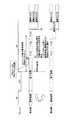
図2は、本実施形態の情報処理装置による特徴的な処理の概略を説明する図の一例である。図2の上段は比較のために示した従来例である。 FIG. 2 is an example of a diagram illustrating an outline of characteristic processing performed by the information processing apparatus according to the present embodiment. The upper part of FIG. 2 is a conventional example shown for comparison.
まず、イグニッション(IG)=OFFからONになるとリセットの後、初期処理(以下、プライマリチェック(P/C)という)が開始される(不図示)。そして、通常タスクが開始されるが、IG=ONからIG=OFFになると、通常タスクが終了し、ECUは終了処理を開始する。以下、終了処理を実行するソフトを終了処理ソフト、P/Cを実行するソフトをP/Cソフト、通常タスクを実行するソフトを制御アプリという。
(1)終了処理ソフトは、終了処理の実行中にIG=OFFからIG=ONを検出すると「ON時刻」を記録する。なお、このIG=ONにより、他のECUが処理を開始するまでのデッドラインが定まる。
(2)終了処理ソフトが終了すると、IG=ONを検出しているため、ECUはCPUをリセットすることで、P/Cソフトを起動する。P/Cソフトはいくつかの(図では3つ)独立して実行可能な処理(P/C1〜3)に区分されている。P/Cソフトは、記録されているON時刻と現在時刻の差から、IG=ONからの経過時間を求める。また、全P/Cに必要な時間は固定なので、P/Cソフトにとって既知である。
(3)P/Cソフトは、デッドライン時間から経過時間を減じて残時間を算出する。そして、残時間内に終了するP/Cを選択し、選択したP/Cだけを実行する。図ではP/C1とP/C2が実行されている。First, when the ignition (IG) is turned from OFF to ON, an initial process (hereinafter referred to as primary check (P / C)) is started after reset (not shown). Then, the normal task is started. When IG = ON is changed to IG = OFF, the normal task is ended and the ECU starts the end process. Hereinafter, software for executing the end process is referred to as end process software, software for executing P / C is referred to as P / C software, and software for executing a normal task is referred to as a control application.
(1) The termination processing software records “ON time” when IG = OFF to IG = ON are detected during the termination processing. Note that the deadline until another ECU starts processing is determined by this IG = ON.
(2) When the termination processing software ends, since IG = ON is detected, the ECU starts the P / C software by resetting the CPU. The P / C software is divided into several (three in the figure) processes (P / C1 to 3) that can be executed independently. The P / C software obtains the elapsed time from IG = ON from the difference between the recorded ON time and the current time. Also, since the time required for all P / C is fixed, it is known to the P / C software.
(3) The P / C software calculates the remaining time by subtracting the elapsed time from the deadline time. Then, the P / C that ends within the remaining time is selected, and only the selected P / C is executed. In the figure, P / C1 and P / C2 are executed.
P/Cを実行した後は、ECUは制御アプリの起動を開始する。したがって、通常タスクは必ずデッドラインが到来する前に開始されることができる。また、部分的にでもP/Cを実行することでECUハード及びマイコンの信頼性確保を達成できる。 After executing P / C, the ECU starts the control application. Thus, normal tasks can always be started before the deadline arrives. Moreover, the reliability of ECU hardware and a microcomputer can be ensured by executing P / C even partially.
なお、後の実施例で説明するように、P/Cソフトは、通常タスクを開始した後、実行していないP/Cを実行することもできる。 As will be described later, the P / C software can execute a P / C that has not been executed after starting a normal task.
図3は、本実施例のP/Cの実行方法が適用されたECUを含む電源供給システムの概略構成図の一例である。電源供給システムは、照合ECU11、電源制御IC12、IGリレー14、及び、HV−ECUを有している。 FIG. 3 is an example of a schematic configuration diagram of a power supply system including an ECU to which the P / C execution method of the present embodiment is applied. The power supply system includes a
照合ECU11は、電子キー(スマートキー(登録商標))を照合して、エンジンを始動させてよい状態であることを電源制御IC12に通知する。すなわち、照合ECU11は、例えばカーテシスイッチによるドアの開閉により運転者が乗車したと推定すると、車内のアンテナで車内の電子キーと通信して、IDコードを認証し認証が成立すると電源制御IC12に車内照合が成立したことを通知する。 The
電源制御IC12は、ブレーキペダルが踏み込み操作された状態でスタートスイッチ(IG)が押圧操作(ON)された事を検出すると、車内照合の成立を条件としてIGリレー14をオンにする。これにより電源からHV−ECU13に電力が供給される。また、電源制御IC12は、HV−ECU13に起動信号を出力し、スタートスイッチが押圧操作(OFF)されるとHV−ECU13に終了信号を出力する。
HV−ECU13は、ハイブリッドシステムの全体を制御するECUであり、不図示のエンジンECUとモータECUと接続されている。HV−ECU13は、電源制御IC12からの起動信号により起動する(リセットしてP/Cを実行)。HV−ECU13は、電源制御IC12からの終了信号により終了処理を開始する。終了処理中に、起動信号を取得した場合、HV-ECUは起動信号の取得を記録しておくことになる。HV−ECU13が起動した後、HV−ECU13は不図示のリレーをオンにすることで、ハイブリッド系統の機器も起動するようになっている。When the power
The HV-
図4は、HV−ECU13の機能ブロック図の一例を示す。HV−ECU13は、CPU22、ROM23、RAM、EEPROM、I/O等がバスを介して接続されたコンピュータである。なお、CPUは好ましくはマルチコアを有しており、複数の処理を並行に実行することができる。 FIG. 4 shows an example of a functional block diagram of the HV-
HV−ECU13は、CPU22がROM23に記憶されたプログラムを実行することにより実現される、初期タスク実行部31、通常タスク実行部32、及び、終了処理部33を有する。なお、ROM23にはP/Cソフト、制御アプリ、及び、終了処理ソフトが記憶されており、初期タスク実行部31はP/Cソフトの実体、通常タスク実行部32の制御アプリの実体、終了処理部33は終了処理ソフトの実体とする。また、初期タスク実行部31は、タスク制御部34を有する。なお、これらの一部以上をハードウェアにより実現してもよい。 The HV-
HV−ECU13は、エンジンが出力すべき動力、モータが出力すべき動力、制動時の回生制動量、等を演算する処理を行う。これらはHV−ECU13が一般に行うタスクであり通常タスクに相当する。通常タスク実行部32は、図1にて説明したように機能統合により統合されたCANゲートウェイに関する処理を行う。また、通常タスク実行部32は、一般的な処理として、アクセルペダル開度、ブレーキペダルの踏み込み量、シフトポジション、モータジェネレータを流れる電流値、モータジェネレータの回転速度に基づき、モータジェネレータMG1,MG2の3相コイルに流す電流を決定し、決定した電流値に応じた駆動信号をインバータへ出力する。 The HV-
また、通常タスク実行部32は、同様の車両状態に基づき、エンジンによる動力が必要と判断すれば、エンジンが出力すべき動力を演算してエンジンECUに指示する。また、通常タスク実行部32は、ブレーキペダルの踏み込み量によって車両の減速を検知すると、回生エネルギーを効率的に回収するため、変速機における減速比を高くする。また、ブレーキペダルの踏み込み量に基づいて要求制動力を演算し、要求制動力と、SOC(State Of Charge)と、回転速度とに基づいて、モータジェネレータの回生量を演算し、ブレーキアクチュエータが提供すべき回生量をブレーキECUに指示する。 Further, if the normal
通常タスク実行部32は、このような処理を並行的に実行しており、各処理は制御アプリとして分離可能であるか、又は、少なくともCPU22が判別できるようになっている。通常タスク実行部32は、初期タスク実行部31がP/Cを実行した後、例えばタスク制御部34に呼び出されることで開始され、通常タスクを開始する。 The normal
なお、各通常タスクは、上記のように他のECUとの関係で、IG=ONを基準に実行を開始しなければならないデッドラインが決まっている。デッドラインは例えば240ミリ秒であるが、通常タスク毎に異なる場合もある。 Each normal task has a deadline that must be executed on the basis of IG = ON in relation to other ECUs as described above. The deadline is, for example, 240 milliseconds, but may be different for each normal task.
初期タスク実行部31は、HV−ECU13のハードが正常か否かをチェックするP/Cを実行する。P/Cとしては、例えば、リセット回路21のチェック、ROMチェック、RAMチェック、チェックSUM、基板上の各チップ間の通信のチェック等が挙げられる。 The initial
リセット回路21のチェックは、例えば、CPU22から所定の信号を送信した際に実際にCPU22がリセットされるか否かをチェックする処理である。ROMチェックやRAMチェックは、ROMからデータが正常に読み出せるか否か、書き込みした内容が正しく読み出させるか否か、等をチェックする処理である。チップ間の通信のチェックは、例えばリセット回路を管理している不図示の監視ICと通常タスクを実行するマイコン間の通信のチェックである。これらのP/Cは、初期タスク実行部31が1つ以上を選択的に実行できるようにそれぞれが独立している。 The check of the reset circuit 21 is a process of checking whether or not the
終了処理部33は、アクチュエータを安全に停止させる処理、ECUハードのアクセスを適切に終了させる処理、ECUやハードの設定を記憶する処理、等である。終了処理部33が、行うべき終了処理の種類は有限であるが、実際にどの処理を行うかは、IG=OFFの際のHV−ECU13の状態に依存する。終了処理部33はHV−ECU13の状態に基づき、実行すべき全ての終了処理を実行する。 The termination processing unit 33 includes a process for safely stopping the actuator, a process for appropriately terminating access to the ECU hardware, a process for storing settings of the ECU and hardware, and the like. The types of end processing to be performed by the end processing unit 33 are limited, but which processing is actually performed depends on the state of the HV-
タスク制御部34は、初期タスク実行部31が実行するP/Cを決定する。タスク制御部34は例えばOSのタスク制御機能を利用することもできる。本実施例では、タスク制御部34は、IG=ONになったON時刻から終了処理が完了するまでの経過時間を、デッドラインから減じて、実行可能なP/Cを決定する。初期タスク実行部31は決定されたP/Cを実行する。 The
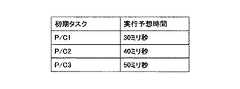
このため、タスク制御部34は、実行可能なP/Cを決定するため、各P/Cの実行予想時間を記憶している。
図5は各P/Cの実行予想時間を示す図の一例である。例えば、各P/Cの実行予想時間の合計が、デッドラインから経過時間を減じた残時間よりも長い場合、全てのP/Cは実行できないことが分かる。Therefore, the
FIG. 5 is an example of a diagram showing the estimated execution time of each P / C. For example, if the total estimated execution time of each P / C is longer than the remaining time obtained by subtracting the elapsed time from the deadline, it can be understood that not all P / C can be executed.
図2に示したように、本実施例のHV−ECU13は、搭載される通常タスクのデッドラインまでにP/Cが完了できないと予想した場合、デッドラインまでの時間に応じてP/Cを部分的に実行する。図2の上段は従来の処理におけるタイミングチャート図であり、終了処理が長引いた後、HV-ECU13が実行すべきP/Cを3つ実行することで、デッドラインまでに通常タスクが開始できなったことを示している。 As shown in FIG. 2, when the HV-
これに対し、図2の下段のタイムチャート図では、HV−ECU13が実行するP/Cを2つに制限したことで、デッドラインまでに通常タスクが開始されていることを示している。このような処理を実現するため、HV−ECU13は、以下の処理を実行する。 On the other hand, the time chart at the lower part of FIG. 2 shows that the normal task is started by the deadline by limiting the P / C executed by the HV-
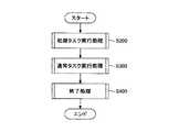
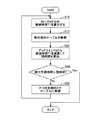
図6は、HV−ECU13がP/Cと通常タスクを実行する手順を示すフローチャート図の一例である。図6では、初期タスク実行処理(S200)、通常タスク実行処理(S300)、及び、終了処理(S400)の順に記述されている。これらの処理は、繰り返し実行の必要性が判断され、必要な処理のみが実行される。 FIG. 6 is an example of a flowchart illustrating a procedure in which the HV-
図7(a)〜(c)は初期タスク実行処理、通常タスク実行処理、及び、終了処理の手順を示すフローチャート図の一例である。すでに、初期タスク実行処理と通常タスク処理はすべて起動され、終了処理が起動されたものとして説明する。 FIGS. 7A to 7C are examples of flowcharts showing procedures of initial task execution processing, normal task execution processing, and end processing. A description will be given assuming that all of the initial task execution process and the normal task process have already been started and the end process has been started.
IG=OFFになると図7(c)のステップS410の判定がYesとなる。終了処理部33は、終了処理の間(S410のYes)、IGリレー14の状態がIG=OFFからIG=ONへ操作されたか否かを判定している(S420)。 When IG = OFF, the determination in step S410 in FIG. 7C is Yes. The termination processing unit 33 determines whether or not the state of the
IG=ONになった場合(S420のYes)、終了処理部33はIG=OFFからIG=ONへ操作されたON時刻を記録する(S430)。その後、終了処理部33は、引き続き終了処理を実施する(S440)。 When IG = ON (Yes in S420), the end processing unit 33 records the ON time when the operation is performed from IG = OFF to IG = ON (S430). Thereafter, the end processing unit 33 continues the end processing (S440).
そして、終了処理が完了しない場合(S450のNo)、処理はステップS200から繰り返されるがS200、S300が実行されることはなく、引き続き終了処理のS400においてS410の判定がYesとなる。 If the end process is not completed (No in S450), the process is repeated from Step S200, but S200 and S300 are not executed, and the determination in S410 is Yes in S400 of the end process.
終了処理が完了すると(S450のYes)、例えばON時刻が記録されていることからHV-ECUの起動が必要だと判断して、終了処理部33はリセット回路21により自身をリセットする。これにより、HV−ECU13は再起動し、初期タスク実行部31、通常タスク実行部32等が起動される(S460)。具体的には、CPU22はROM23の予め定められたブート部のアドレスをプログラムカウンタに設定し、ブートプログラムを実行する。ブートプログラムは、CPU22にパラメータや定数を初期値として設定する。ブートプログラムは、まず、初期タスク実行部31のアドレスをプログラムカウンタに設定し、以降は初期タスク実行部31やタスク制御部34の処理が開始する。 When the end process is completed (Yes in S450), for example, since the ON time is recorded, it is determined that the HV-ECU needs to be started, and the end processing unit 33 resets itself by the reset circuit 21. Accordingly, the HV-
図7(a)の処理に移動し、まず、初期タスク実行部31は、プログラムの初回起動か否かを判定する(S210)。プログラムの初回起動とは、IG=ON後、初めて初期タスク実行処理等が実行されたことをいう。この判定は、P/Cがすでに実行されたか否かを判定するための処理であり、次術する初期タスクテーブルに登録されたP/Cに実行フラグが登録されているか否かにより判定される。 Moving to the processing of FIG. 7A, first, the initial
初期タスク実行処理が初回起動の場合(S210のYes)、タスク制御部34は、初期タスクテーブルにP/Cを登録する(S220)。初期タスク実行部31は、実行可能なP/Cを決定し初期タスクテーブルに登録する。
図8は、タスク制御部34が、実行可能なP/Cを決定し初期タスクテーブルに登録する手順を示すフローチャート図の一例である。すでに説明したように、終了処理部33が電源制御IC12から起動信号が入力された時の時刻(絶対時刻)をROM23等に記憶している。本実施例ではミリ秒単位の精度が必要なので、絶対時刻ではミリ秒単位の精度がない場合、終了処理部33は、クロックなどで増減するタイマをセットしてもよい。タスク制御部34は、クロック周波数とタイマの値から経過時間をミリ秒レベルで算出することができる。When the initial task execution process is activated for the first time (Yes in S210), the
FIG. 8 is an example of a flowchart illustrating a procedure in which the
タスク制御部34は、ON時刻又はタイマを参照して、IG=ONからの経過時間T1を算出する(S10)。 The
次に、予め記憶しているデッドラインTdから経過時間T1を減算して残時間を算出する(S20)。残時間=Td−T1
各P/Cの実行予測時間を読み出し合計してその時間を合計実行予測時間とする。タスク制御部34は、合計実行予測時間が残時間よりも大きいか否かを判定する(S30)。Next, the remaining time is calculated by subtracting the elapsed time T1 from the deadline Td stored in advance (S20). Remaining time = Td-T1
The estimated execution time of each P / C is read and summed, and the time is defined as the total estimated execution time. The
合計実行予測時間が残時間よりも大きくない場合(S30のNo)、全てのP/Cを実行できることになるので、タスク制御部34は初期タスクテーブルに全てのP/Cを登録する(S40)。 If the estimated total execution time is not longer than the remaining time (No in S30), all P / Cs can be executed, so the
合計実行予測時間が残時間よりも大きい場合(S30のYes)、初期タスク実行部31は全てのP/Cを実行できないので、タスク制御部34は実行すべきP/Cを決定する(S50)。 If the estimated total execution time is greater than the remaining time (Yes in S30), the initial
決定方法については後の実施例にて説明するが、例えば、タスク制御部34は、最も優先度の高い2つのP/Cの実行予測時間を読み出したり、ランダムに2つのP/Cの実行予測時間を読み出し、その合計実行予測時間が残時間よりも大きいか否かを判定する。合計実行予測時間が残時間よりも大きくない場合、この2つのP/Cを実行できることになるので、タスク制御部34は初期タスクテーブルに、2つのP/Cを登録する。 The determination method will be described in a later embodiment. For example, the
合計実行予測時間が残時間よりも大きい場合、タスク制御部34は2つのP/Cは実行できないと判定し、ランダムに1つのP/Cの実行予測時間を読み出し、その実行予測時間が残時間よりも大きいか否かを判定する。実行予測時間が残時間よりも大きくない場合、このP/Cを実行できることになるので、タスク制御部34は初期タスクテーブルにこのP/Cを登録する。 When the total execution prediction time is longer than the remaining time, the
1つのP/Cでも実行予測時間が残時間よりも大きい場合、P/Cを実行する余裕がないとして、タスク制御部34は初期タスクテーブルにP/Cを登録しない。
図7(a)に戻り、初期タスク実行部31は初期タスクテーブルに登録されたP/Cをすべて実行する(S230)。こうすることで、デッドラインまでにP/Cを実行することができた。If even one P / C has a predicted execution time longer than the remaining time, the
Returning to FIG. 7A, the initial
P/Cの実行が完了すると、通常タスク実行部32が通常タスクを開始する。図7(b)の処理に移り、通常タスク実行部32は、起動していない通常タスクがあるか否かを判定する(S310)。 When the execution of P / C is completed, the normal
起動していない通常タスクがある場合(S310のYes)、通常タスク実行部32は記憶されているON時刻から現在時刻までの経過時間を算出する(S320)。 When there is a normal task that has not been activated (Yes in S310), the normal
通常タスク実行部32は、起動していない通常タスクのうち最も近いデッドラインと、経過時間を比較する(S330)。 The normal
通常タスク実行部32は、その通常タスクのデッドライン時刻が到来したか否かを判定する(S340)。この判定は、例えば、デッドラインから経過時間を減じた値が所定値以下になったことを基準とする。なお、本実施例ではデッドライン時刻の到来を待たずに、通常タスクを実行してもよい。 The normal
通常タスクのデッドライン時刻が到来した場合(S340のYes)、通常タスク実行部32はデッドラインになった通常タスクを実行する(S350)。通常タスク実行部は通常タスクの起動を繰り返して、すべての通常タスクを起動する。 When the deadline time of the normal task has arrived (Yes in S340), the normal
以上のようにして、HV−ECU13はP/Cを必ずデッドラインまでに終わらせることができる。1つもP/Cが実行できないことは希なので、HV−ECU13は実際には1つ以上のP/Cを実行できるとしてよい。したがって、ECUや関連するハードウェアが正常であることを確認でき、信頼性を確保することができる。 As described above, the HV-
実施例1では、全てのP/Cを実行できない場合、タスク制御部34が優先度順やランダムにP/Cを決定した。しかしこの方法では、実行されるP/Cに偏りが生じるおそれもあるため、実行すべきP/Cは信頼性が確保できるように恣意的に決定することが好ましい。 In the first embodiment, when all the P / Cs cannot be executed, the
そこで、本実施例では、全てのP/Cを実行できない場合、実行回数の最も少ないP/Cを選択するHV−ECU13について説明する。 Therefore, in this embodiment, a description will be given of the HV-
図9は、HV−ECU13のタイミングチャート図の一例を示す。図9において図2と同一部の説明は省略する。図2と同様に、P/Cを決定することで、デッドラインまでにP/Cを終了させることができる。 FIG. 9 shows an example of a timing chart of the HV-
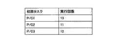
図10は、実行回数テーブルの一例を示す。実行回数テーブルは、例えばROM23に記憶されている。タスク制御部34は、実行するP/Cを決定して初期タスクテーブルに登録した際又はP/Cの実行が完了する毎、実行回数テーブルに登録されているP/Cの実行回数を1つ大きくする。これにより、タスク制御部34は、次回、実行するP/Cを決定する際、実行回数の最も少ないP/Cを実行することができる。 FIG. 10 shows an example of the execution count table. The execution frequency table is stored in the
図11は、初期タスク実行部31が実行するP/Cを決定する手順を示すフローチャート図の一例である。通常タスク実行処理と終了処理については実施例1と同様なので省略する。 FIG. 11 is an example of a flowchart illustrating a procedure for determining a P / C to be executed by the initial
図11の処理では、ステップS32がある点が図8と異なる。ステップS32においてタスク制御部34は、実行回数テーブルを読み出す。図10の実行回数テーブルでは、P/C1が13回、P/C2が11回、P/C3が12回、それぞれ実行されている。このような場合、タスク制御部34は、全てのP/Cを実行できないと判定すると、2つの実行回数の合計が最も少ない組み合わせであるP/C2とP/C3の合計実行予測時間を残時間と比較する。合計実行予測時間が残時間よりも大きくな場合、タスク制御部34はこの2つのP/Cを実行するP/Cに決定する。 The process of FIG. 11 differs from FIG. 8 in that step S32 is present. In step S32, the
合計実行予測時間が残時間よりも大きい場合、別の組み合わせで同様の判定を行ってもよいが、その2つのP/Cが実行できると判定され、初期タスク実行部31が実行すると、各P/C間の実行回数の差が増大することになる。しかしながら、可能な限りP/Cを処理することでHV−ECU13の信頼が増すとも考えられる。したがって、別の組み合わせで同様の判定を行うか否かはP/Cの実行ポリシーによって決定することができる。 If the total execution prediction time is larger than the remaining time, the same determination may be performed with another combination. However, when it is determined that the two P / Cs can be executed and the initial
2つのP/Cの合計実行予測時間が残時間よりも大きい場合、タスク制御部34は、実行回数が最も少ないP/C2の実行予測時間を残時間と比較する。実行予測時間が残時間よりも大きくない場合、タスク制御部34はこのP/Cを実行するP/Cに決定する。1つのP/Cも実行できないことは少ないので、最も実行回数が少ないP/Cを実行することで、各P/Cの実行回数を均等化させることができる。 When the estimated total execution time of the two P / Cs is larger than the remaining time, the
〔変形例〕
実行回数テーブルに過去の全ての実行回数を登録するのでなく、過去のP/Cの実行機会のうち最新の所定回数から実行回数を求めてもよい。なお、P/Cの実行機会とは、HV−ECU13が再起動された回数である。[Modification]
Instead of registering all past execution counts in the execution count table, the execution count may be obtained from the latest predetermined number of past P / C execution opportunities. The P / C execution opportunity is the number of times the HV-
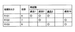
図12は、この変形例の実行回数テーブルの一例を示す。この実行回数テーブルには、P/C毎に、過去の最新の10回の再起動のうち、実際に実行されたP/Cが記録(“○”により示す)される。また、過去の最新の10回の再起動において、各P/Cが実行された回数が記録されている。実行回数テーブルはリングバッファのように、過去10まで記録すると記録先が過去1に戻るので、最後の記録先が明示されている(図では過去3が最後の記録先であることを下線で示すが、実際には実行回数テーブルの記録先を示すアドレスやポインタで示される。)。 FIG. 12 shows an example of the execution frequency table of this modification. In this execution count table, for each P / C, P / C actually executed out of the latest 10 restarts in the past is recorded (indicated by “◯”). In addition, the number of times each P / C is executed in the latest 10 restarts in the past is recorded. In the execution frequency table, the recording destination returns to the past 1 when recording up to the past 10 as in the ring buffer, so the last recording destination is clearly indicated (in the figure, the past 3 is indicated by the underline as the last recording destination). (In fact, it is indicated by an address or pointer indicating the recording destination of the execution count table.)
タスク制御部34は、実行するP/Cを決定した際、最後の記録先の次の記録先のP/Cに「○」を登録する。そして、P/C毎に実行回数をカウントし、各P/Cが実行された合計を更新する。タスク制御部34は、フローチャート図のステップS32において、実行回数テーブルを読み出し、すでに説明したようにして実行するP/Cを決定する。 When the
このように、最新の履歴を参照して実行すべきP/Cを決定することで、その時点でのHV−ECU13の信頼性を確実に検出し、効果的に信頼性を確保することができる。 Thus, by determining the P / C to be executed with reference to the latest history, the reliability of the HV-
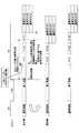
これまではデッドラインは制御アプリに共通であるかのように説明したが、デッドラインは他のECUが実行するプログラムとの関係により定まることが多いので、実際には複数の制御アプリのデッドラインが異なることもある。 Until now, the deadline was explained as if it were common to the control apps, but since the deadline is often determined by the relationship with the program executed by other ECUs, the deadlines of multiple control apps are actually used. May be different.
図13は、HV−ECU13のタイミングチャート図の一例を示す。図13において図2と同一部の説明は省略する。図13の下段では、通常タスクBと通常タスクA,Cとでデッドラインが異なっている。この場合、タスク制御部34は、最もデッドラインが近い制御アプリBのデッドラインに対し、全てのP/Cが実行できるか否か、及び、実行できない場合はどのP/Cを実行するかを決定する必要がある。 FIG. 13 shows an example of a timing chart of the HV-
ここで、各通常タスクには関連の強いP/Cが存在する。通常タスクによっては、EEPROMへの書き込み、特定のICの動作、ADコンバータの変換など、制御アプリが必要とするハードウェアリソースが異なるためである。したがって、デッドラインが最も近い通常タスクに関連するP/Cを優先して実行すれば、よりデッドラインが遅い制御アプリに関連するP/Cを実行する余裕が生じることが期待できる。 Here, each normal task has a strongly related P / C. This is because, depending on the normal task, hardware resources required by the control application such as writing to the EEPROM, operation of a specific IC, and conversion of an AD converter are different. Therefore, if priority is given to the P / C related to the normal task with the closest deadline, it can be expected that there will be room for executing the P / C related to the control application with the slower deadline.
各通常タスクのデッドライン及び通常タスクと関連の強いP/Cは固定であるので、この情報を使えば、優先的に実行すべきP/Cを決定することができる。
図14(a)は各通常タスクのデッドラインと、通常タスクと関連の強いP/Cを示す図の一例である。例えば、通常タスクAのデッドラインはTaミリ秒であり、関連の強いP/CはP/C1〜3である。通常タスクBのデッドラインはTbミリ秒であり、関連の強いP/CはP/C1、2である。通常タスクCのデッドラインはTcミリ秒であり、関連の強いP/CはP/C3である。Since the deadline of each normal task and the P / C strongly associated with the normal task are fixed, this information can be used to determine the P / C to be preferentially executed.
FIG. 14A is an example of a diagram showing a deadline of each normal task and a P / C strongly associated with the normal task. For example, the deadline of normal task A is Ta milliseconds, and the strongly related P / C is P / C1-3. Normally, the deadline of task B is Tb milliseconds, and the strongly related P / C is P / C1,2. Normally, the deadline of task C is Tc milliseconds, and the strongly related P / C is P / C3.
説明のため、Tb<Ta、Tcとする。したがって、通常タスクBのデッドラインが最も短いので、通常タスクBと関連が強いP/C1,2を優先的に実行すべきであることが分かる。タスク制御部34は、このようにして決定されたP/Cの実行順序テーブルを記憶している。 For explanation, it is assumed that Tb <Ta and Tc. Therefore, it can be seen that the deadline of the normal task B is the shortest, so that P / C1 and P2, which are strongly related to the normal task B, should be preferentially executed. The
図14(b)は実行順序テーブルの一例を示す。実行順序テーブルはROM23に記憶されている。実行順序テーブルには、デッドラインが最も短い通常タスクBと関連が強いP/C1,2が、実行順番の1番と2番になっている。タスク制御部34は、実行すべきP/Cを決定する際、実行順序テーブルを参照して実行するP/Cを決定する。こうすることで、デッドラインが短いP/Cを優先的に実行することができる。 FIG. 14B shows an example of the execution order table. The execution order table is stored in the
図15は、HV−ECU13が実行するP/Cを決定する手順を示すフローチャート図の一例である。図15の処理では、ステップS10の処理は図8と同様である。 FIG. 15 is an example of a flowchart illustrating a procedure for determining the P / C executed by the HV-
S12において、タスク制御部34は実行順序テーブルを読み出す(S12)。タスク制御部34は実行順序テーブルを用いて実行すべきP/Cを決定する。タスク制御部34は、まず実行順序テーブルのすべてのP/Cのから実行順序が一番のP/Cを特定する。 In S12, the
そのP/CのデッドラインTdを読み出し、経過時間T1を減算して残時間を算出する(S20)。次に、タスク制御部34は特定したP/Cの実行予想時間を読み出す。 The P / C deadline Td is read, and the remaining time is calculated by subtracting the elapsed time T1 (S20). Next, the
タスク制御部34は、実行予測時間が残時間よりも大きいか否かを判定する(S30)。 実行予測時間が残時間よりも大きくない場合(S30のNo)、タスク制御部34はそのP/Cをデッドラインまでの実行できると判定して、初期タスクテーブルに登録する(S52)。この場合、初期タスク実行部31は初期タスクテーブルに登録されたP/Cから順次、実行する。 The
1つのP/Cの実行後、処理はステップS10に戻り、タスク制御部34は実行順が2番目以降のP/Cについて同様の処理を繰り返す。これにより、デッドラインが近い制御タスクと関連の大きい順にP/Cを実行することができる。 After execution of one P / C, the process returns to step S10, and the
なお、実行予測時間が残時間よりも大きい場合(S30のYes)、デッドラインまでにP/Cを実行完了できないので、図15の処理は終了する。 If the predicted execution time is longer than the remaining time (Yes in S30), the execution of P / C cannot be completed by the deadline, so the processing in FIG. 15 ends.
本実施例のHV−ECU13は、通常タスクのデッドラインと通常タスクに関連の強いP/Cを考慮して実行順序を決定し、P/C毎にデッドラインまでの残時間を算出するので、優先順位の高いP/Cを優先的に実行でき、また、デッドラインの遅いP/Cを実行する機会を増やすことができる。 The HV-
実施例3では実行順序テーブルに基づきデッドラインの近い通常タスクと関連の強いP/Cを優先的に実行することができるが、実行順序テーブルだけに基づいてP/Cを決めると、実行されない又は実行回数が極端に少ない通常タスクが生じるおそれがある。 In the third embodiment, it is possible to preferentially execute a P / C having a strong relationship with a normal task having a close deadline based on the execution order table. However, if the P / C is determined based only on the execution order table, it is not executed or There is a possibility that a normal task with an extremely small number of executions may occur.
そこで、本実施例では、実施例2と同様に実行回数テーブルを利用して、実行回数が規定回数を満たさないP/Cは、実行を中止することなく実行するHV−ECU13について説明する。なお、実行回数テーブルは過去の全ての実行回数を登録されていてもよいし、最新の所定回数の実行回数だけが登録されていてもよい。 Therefore, in the present embodiment, the HV-
図16はタイミングチャート図の一例である。図16の中段は実施例3と同様のタイミングチャート図である。すなわち、デッドラインが最も近い通常タスクBに関連するP/Cのみが優先して実行されている。これに対し、図16の下段は、P/C3の実行回数が規定回数を満たしていないため、デッドラインが最も近い通常タスクBよりも優先して、P/C3が実行されている。このため、下段が上段と同様のタイミングチャート図となるが、規定回数を満たさないP/Cを実行することで、HV−ECU13の信頼性を確保できる。 FIG. 16 is an example of a timing chart. The middle part of FIG. 16 is a timing chart similar to that of the third embodiment. That is, only the P / C related to the normal task B with the closest deadline is executed with priority. On the other hand, in the lower part of FIG. 16, since the number of executions of P / C3 does not satisfy the prescribed number, P / C3 is executed in preference to the normal task B with the closest deadline. For this reason, the lower stage is the same timing chart as the upper stage, but the reliability of the HV-
図17は、HV−ECU13が実行するP/Cを決定する手順を示すフローチャート図の一例である。ステップS30において実行予測時間が残時間よりも大きくない場合(S30のNo)、タスク制御部34は、実行回数テーブルを読み出し(S32)、そのP/Cを初期タスクテーブルに登録する(S52)。 FIG. 17 is an example of a flowchart illustrating a procedure for determining the P / C executed by the HV-
実行予測時間が残時間よりも大きい場合(S30のYes)、タスク制御部34は、実行回数が規定回数を満たしていないP/Cがあるか否かを判定する(S42)。初期タスク実行部31が実行回数の少ない順にP/Cを実行しても規定回数を満たさない状況は、例えば、車両の出荷直後や初期状態へのリセット後に生じうる。 When the predicted execution time is longer than the remaining time (Yes in S30), the
ここで、過去の全ての実行回数を規定回数と比較すると、P/Cに実行頻度が少ないものがあっても規定回数以上実行されていると判定される。これを防ぐため、実行回数テーブルに過去の全ての実行回数が記録されている場合、タスク制御部34は、最高の実行回数を有するP/Cの実行回数Nmaxに対する他の処理タスクの実行回数Nの比率を求め、比率が規定値N0を満たすか否かに基づき、実行頻度の少ないP/Cを特定する。 Here, when all the past execution times are compared with the specified number of times, it is determined that the P / C has been executed more than the specified number of times even if there is a low execution frequency. In order to prevent this, when all the past execution counts are recorded in the execution count table, the
N/Nmax×100 > 規定値N0(例えば、70%)
なお、実行回数テーブルに過去の所定回数の実行回数が記録されている場合、規定回数(例えば5回)と各P/Cの実行回数を比較すればよい。N / Nmax × 100> prescribed value N0 (for example, 70%)
When the number of executions in the past is recorded in the execution number table, the prescribed number (for example, five times) may be compared with the number of executions of each P / C.
実行回数が規定回数を満たしていないP/Cがある場合(S42のYes)、タスク制御部34は、その全てのP/Cを実行すると決定する(S44)。そして、初期タスク実行部31は、デッドラインと無関係に全てのP/Cを実行する。 When there is a P / C whose number of executions does not satisfy the specified number of times (Yes in S42), the
実行回数が規定回数を満たしていないP/Cがない場合(S42のNo)、図17の処理は終了し、通常タスクが開始される。 If there is no P / C in which the number of executions does not satisfy the specified number of times (No in S42), the process of FIG. 17 ends and a normal task is started.
本実施例によれば、P/Cに一定の実行回数がない場合、通常タスクを遅らせてもP/Cを実行するので、HV−ECU13の信頼性を確保できる。 According to the present embodiment, when the P / C does not have a certain number of executions, the P / C is executed even if the normal task is delayed, so the reliability of the HV-
これまでの実施例では、HV−ECU13が通常タスクの実行を開始した後は、P/Cを実行しないことを前提に説明した。しかし、P/Cは通常タスクを実行した後でも実行することができるので、通常タスクを開始した後、P/Cを実行することでHV−ECU13の信頼性を確保することができる。 In the embodiments so far, the description has been made on the assumption that the P / C is not executed after the HV-
図18は、HV−ECU13のタイミングチャート図の一例を示す。図18において図2と同一部の説明は省略する。図18の下段では、これまでの実施例と同様に一部のP/C1,2のみが実行されているが、その後、P/C3が通常タスクBと並行に実行されている。P/C3は、通常タスクAと関連の強いP/Cであるが、通常タスクAは、P/C3の後に実行すれば、通常タスクAに対するHV−ECU13の信頼性を少なくとも確保することができる。 FIG. 18 shows an example of a timing chart of the HV-
なお、通常タスクBとP/C3の並行処理は、HV−ECU13の資源を時分割したり、CPU22がマルチコア又はマルチCPUを有していることで実現される。 Note that the parallel processing of the normal task B and the P /
図19(a)〜(c)はHV−ECU13がP/Cと通常タスクを実行する手順を示すフローチャート図の一例である。図19(c)は図7(c)と同じものであるので図19(a)(b)について説明する。 FIGS. 19A to 19C are examples of flowcharts illustrating a procedure in which the HV-
図19(a)は初期タスクの実行手順を示すフローチャート図の一例である。まず、初期タスク実行部31は、プログラムの初回起動か否かを判定する(S210)。判定方法は図7と同じである。 FIG. 19A is an example of a flowchart showing an initial task execution procedure. First, the initial
初期タスク実行部31が初回起動の場合(S210のYes)、初期タスク実行部31は、初期タスクテーブルにP/Cを登録する(S240)。ここで登録するP/Cは実行順であるとするので、初期タスク実行部31は例えば、実行順序テーブルを参照し、一番目のP/Cから初期タスクテーブルに登録する。 When the initial
初期タスク実行部31は、一番目のP/Cが未完了か否かを判定する(S250)。未完了の場合(S250のYes)、タスク制御部34は、ON時刻又はタイマを参照して、IG=ONからの経過時間T1を算出する(S261)。 The initial
次に、予め記憶しているデッドラインTdから経過時間T1を減算して残時間を算出する(S262)。残時間=Td−T1
タスク制御部34は、実行予測時間が残時間よりも大きいか否かを判定する(S263)。Next, the remaining time is calculated by subtracting the elapsed time T1 from the deadline Td stored in advance (S262). Remaining time = Td-T1
The
実行予測時間が残時間よりも大きくない場合(S263のNo)、このP/Cを実行できることになるので、タスク制御部34は初期タスクテーブルにP/Cを登録する(S264)。 If the predicted execution time is not longer than the remaining time (No in S263), this P / C can be executed, and the
実行予測時間が残時間よりも大きい場合(S263のYes)、初期タスク実行部31はこのP/Cを実行できないので、図19(a)の処理は終了する。 If the predicted execution time is longer than the remaining time (Yes in S263), the initial
次に、タスク制御部34は実行中のP/Cが完了したか否かを判定する(S270)。実行中のP/Cが完了した場合(S270のYes)、タスク制御部34は、実行順序テーブルの次のP/Cを初期タスクテーブルに登録する(S280)。殆どの場合、初期タスクテーブルの最初のP/Cは実行されると考えらえる。 Next, the
次に、処理は図19(b)に移動するが、図19(b)の処理にてデッドラインに到達していなければ(S340のNo)、P/Cがすべて完了していない限り(S360のNo)、処理は図19(a)に戻る。よって、順次、P/Cが実行されていく。 Next, the process moves to FIG. 19B. If the deadline has not been reached in the process of FIG. 19B (No in S340), unless all P / Cs are completed (S360). No), the processing returns to FIG. Therefore, P / C is executed sequentially.
また、図19(b)の処理にてデッドラインに到達した場合(S340のYes)、通常タスクが実行されるが(S350)、P/Cがすべて完了していない限り(S360のNo)、やはり処理は図19(a)に戻る。よって、順次、通常タスクとP/Cが並行的に実行されていく。 If the deadline is reached in the process of FIG. 19B (Yes in S340), the normal task is executed (S350), but unless all P / Cs are completed (No in S360), Again, the processing returns to FIG. Therefore, the normal task and the P / C are executed in parallel sequentially.
なお、S340において、通常タスク実行部は、最も短いデッドラインから現在の経過時間を減じた残時間が、P/Cの予想実行時間よりも長いか否かに基づき、デッドラインの到来を判定する。こうすることで、P/Cの実行により通常タスクの実行が遅れることを防止できる。 In S34, the normal task execution unit determines the arrival of a deadline based on whether or not the remaining time obtained by subtracting the current elapsed time from the shortest deadline is longer than the expected execution time of P / C. . By doing so, it is possible to prevent the execution of the normal task from being delayed due to the execution of P / C.
このように、1つのP/Cを実行する毎に、通常タスクのデッドラインが到来したか否かを判定し、デッドラインが到来した場合は通常タスクを実行し、P/Cも平行に実行することで、通常タスクのデッドラインを守りながら、すべてのP/Cを実行できる。 In this way, each time one P / C is executed, it is determined whether or not the deadline of the normal task has arrived. If the deadline has arrived, the normal task is executed and the P / C is also executed in parallel. By doing so, all P / Cs can be executed while keeping the deadline of the normal task.
実施例5では、P/Cの実行順を実行順序テーブルに従うとして説明したが、本実施例では、通常タスクのリスクランクに応じた順番にP/Cを実行するHV−ECU13について説明する。 In the fifth embodiment, it has been described that the execution order of P / C follows the execution order table. However, in this embodiment, the HV-
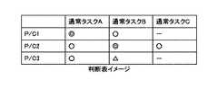
図20は、リスクランクテーブルの一例を示す。リスクランクテーブルは、通常タスクとP/Cの組み合わせ毎に、リスクランクを登録したテーブルである。例えば、通常タスクAについて次のようにリスクランクが登録されている。
通常タスクAとP/C1:高(二重丸)
通常タスクAとP/C2:中(丸)
通常タスクAとP/C3:中(丸)
リスクが高いことはP/Cの必要性が高いことを意味する。なお、「−」はその通常タスクとP/Cの組では、通常タスクがP/Cを実行に影響を受けないことを意味している。FIG. 20 shows an example of the risk rank table. The risk rank table is a table in which risk ranks are registered for each combination of normal tasks and P / C. For example, the risk rank is registered for the normal task A as follows.
Normal task A and P / C1: High (double circle)
Normal task A and P / C2: Medium (circle)
Normal task A and P / C3: Medium (circle)
A high risk means a high need for P / C. Note that “-” means that the normal task is not affected by the execution of the P / C in the pair of the normal task and the P / C.
タスク制御部34は、図20のようなリスクランクテーブルを参照して、優先的に実行すべきP/Cを特定し、実行する。 The
図21は、本実施例のタスク制御部34がP/Cを実行する手順を示すフローチャート図の一例である。図21は、図19(a)の処理とほぼ同じであるが、ステップS240において、タスク制御部34は、デッドラインが最も近い通常タスクのうち最もリスクランクが高いP/Cを特定する。以降の処理は実施例5と同様である。 FIG. 21 is an example of a flowchart illustrating a procedure in which the
本実施例によれば、タスク制御部34は、通常タスクとの関係においてリスクランクの最も高いP/Cから実行することができる。 According to the present embodiment, the
実施例5,6では通常タスクとP/Cの並列可能性を考慮しなかったが、通常タスクとP/Cには並列に実行できない組み合わせもある。例えば、P/Cの1つであるリセット回路21のプライマリチェックは、リセット回路21を駆動して強制リセットさせる処理なので、通常タスクも停止(リセットにより再起動)される。したがって、このような組み合わせでは(この場合、リセットと並列に実行可能な通常タスクはないが)、初期化タスクの優先度を下げ、並列に実行されないように担保する必要がある。 In the fifth and sixth embodiments, the parallel possibility of the normal task and the P / C is not considered, but there are combinations of the normal task and the P / C that cannot be executed in parallel. For example, the primary check of the reset circuit 21 which is one of the P / Cs is a process for driving the reset circuit 21 to forcibly reset, so that the normal task is also stopped (restarted by reset). Therefore, in such a combination (in this case, there is no normal task that can be executed in parallel with reset), it is necessary to lower the priority of the initialization task and ensure that it is not executed in parallel.
図22は、通常タスクと並行に実行可能なP/Cが登録された実行可能初期タスクテーブルの一例を示す。図では「×」と記入されている通常タスクとP/Cの組み合わせにおいて、その通常タスクとP/Cを並列には実行できないことが示されている。なお、「×」となる組み合わせには、リセット回路21の他、ハードウェアリソースの競合などがある。 FIG. 22 shows an example of an executable initial task table in which P / Cs that can be executed in parallel with normal tasks are registered. In the figure, it is shown that the normal task and P / C cannot be executed in parallel in the combination of the normal task and P / C marked with “x”. Note that the combination of “x” includes hardware resource competition in addition to the reset circuit 21.
図23は、本実施例のタスク制御部34がP/Cを実行する手順を示すフローチャート図の一例である。図23は、図21の処理と同様であるが、ステップS240において特定された、実行順序テーブルにおいて実行順が次のP/C又は最もリスクランクが高いP/Cに対し、タスク制御部34は、そのP/Cと並列に実行できない通常タスクが実行されているか否かを判定する(S242)。すなわち、実行可能初期タスクテーブルを参照し、すでに実行されている全ての通常タスクについて特定したP/Cに「×」が登録されていないかどうかを確認する。 FIG. 23 is an example of a flowchart illustrating a procedure in which the
登録されていた場合は(S242のYes)、ステップS240に戻り、タスク制御部34は、再度、実行順序テーブルにおいて実行順が次のP/C又は最もリスクランクが高いP/Cを特定する。これを繰り返すことにより、通常タスクと並列に実行できるP/Cを特定することができる。 If registered (Yes in S242), the process returns to step S240, and the
以上のように、本実施例のHV−ECU13は、P/Cを実行する余裕がない場合でも、通常タスクのデッドラインと経過時間に応じてP/Cを実行できるので、部分的にでもP/Cを実行することができる。よって、ECUハード及びマイコンの信頼性確保を達成できる。また、通常タスクを開始した後、実行していないP/Cを実行することで、信頼性を確保することができる。 As described above, the HV-
11 照合ECU
12 電源制御IC
13 HV−ECU
14 IGリレー
21 リセット回路
22 CPU
23 ROM
31 初期タスク実行部
32 通常タスク実行部
33 終了処理部
34 タスク制御部11 Verification ECU
12 Power control IC
13 HV-ECU
14 IG relay 21
23 ROM
31 Initial
Claims (11)
Translated fromJapanese前記タスクの開始までに実行すべき複数の初期処理タスク及び該初期処理タスク毎の予想実行時間が登録された初期処理タスクテーブルと、
前記起動指示を受け付けた起動指示時刻を記録する起動指示時刻記録手段と、
前記期限から前記起動指示時刻からの経過時間を減じた残時間と、前記予想実行時間を比較して、前記期限までに実行する前記初期処理タスクを決定するタスクスケジュール手段と、
前記初期処理タスクを実行する初期処理タスク実行手段と、
を有することを特徴とする情報処理装置。An information processing apparatus that executes a task for which a time limit from start instruction to start of start is determined,
An initial processing task table in which a plurality of initial processing tasks to be executed before the start of the task and an expected execution time for each initial processing task are registered;
An activation instruction time recording means for recording an activation instruction time at which the activation instruction is received;
A task schedule means for comparing the estimated execution time with a remaining time obtained by subtracting an elapsed time from the start instruction time from the deadline, and determining the initial processing task to be executed by the deadline;
Initial processing task execution means for executing the initial processing task;
An information processing apparatus comprising:
前記タスクスケジュール手段は、前記実行順序テーブルに登録されている前記初期処理タスクの順に、該初期処理タスクの後に実行される前記タスクの前記期限から求められた前記残時間と前記初期処理タスクの前記予想実行時間を比較して、前記残時間内に実行可能な前記初期処理タスクを決定する、
ことを特徴とする請求項1記載の情報処理装置。Based on the initial processing task to be executed before the task and the deadline for each task, an execution order table in which the initial processing tasks to be executed before the task are registered in the order of execution is registered in order of execution. Have
The task scheduling means, in the order of the initial processing tasks registered in the execution order table, the remaining time obtained from the deadline of the tasks executed after the initial processing task and the initial processing tasks. Comparing the expected execution time to determine the initial processing task that can be executed within the remaining time;
The information processing apparatus according to claim 1.
前記タスクスケジュール手段は、前記実行回数が最も少ない前記初期処理タスクを前記期限までに実行すると決定する、
ことを特徴とする請求項1記載の情報処理装置。An execution number table in which the number of executions for each initial processing task is registered;
The task scheduling means determines to execute the initial processing task with the smallest number of executions by the deadline;
The information processing apparatus according to claim 1.
前記残時間が前記予想実行時間より短くても、前記タスクに優先して前記初期処理タスクを実行すると決定する、
ことを特徴とする請求項1記載の情報処理装置。The task schedule unit compares the number of executions of the execution number table with a predetermined number of times, and when there is the initial processing task that does not satisfy the predetermined number of times,
Even if the remaining time is shorter than the expected execution time, it is determined to execute the initial processing task in preference to the task.
The information processing apparatus according to claim 1.
前記起動指示を受け付けた起動指示時刻を記録する起動指示時刻記録手段と、
前記タスクの開始までに実行すべき複数の初期処理タスク及び該初期処理タスク毎の予想実行時間が登録された初期処理タスクテーブルと、
前記初期処理タスクが実行順に登録された実行順序テーブルと、
前記実行順序テーブルに基づき決定した前記初期処理タスクの前記予想実行時間が、前記期限から前記起動指示時刻からの経過時間を減じた残時間以下の場合、前記実行順序テーブルに基づき決定した前記初期処理タスクを実行すると決定するタスクスケジュール手段と、
前記初期処理タスクを実行する初期処理タスク実行手段と、
前記期限が到来した前記タスクを実行するタスク実行手段と、
ことを特徴とする情報処理装置。An information processing apparatus that executes a task for which a time limit from start instruction to start of start is determined,
An activation instruction time recording means for recording an activation instruction time at which the activation instruction is received;
An initial processing task table in which a plurality of initial processing tasks to be executed before the start of the task and an expected execution time for each initial processing task are registered;
An execution order table in which the initial processing tasks are registered in the order of execution;
The initial process determined based on the execution order table when the expected execution time of the initial process task determined based on the execution order table is equal to or less than a remaining time obtained by subtracting an elapsed time from the start instruction time from the deadline. A task scheduling means for determining to execute the task;
Initial processing task execution means for executing the initial processing task;
Task execution means for executing the task that has reached the deadline;
An information processing apparatus characterized by that.
前記タスク実行手段が前記期限が到来した前記タスクを実行し、
前記初期処理タスク実行手段と前記タスク実行手段が、前記初期処理タスクと前記タスクを時分割して実行する、
ことを特徴とする請求項5記載の情報処理装置。The task schedule means, when the expected execution time of the initial processing task determined based on the execution order table is longer than the remaining time, without executing the initial processing task determined based on the execution order table,
The task execution means executes the task that has reached the deadline;
The initial processing task execution means and the task execution means execute the initial processing task and the task in a time-sharing manner;
The information processing apparatus according to claim 5.
前記起動指示を受け付けた起動指示時刻を記録する起動指示時刻記録手段と、
前記タスクの開始までに実行すべき複数の初期処理タスク及び該初期処理タスク毎の予想実行時間が登録された初期処理タスクテーブルと、
前記タスクの機能上、必要性が高い順に前記初期処理タスクが登録されたリスクランクテーブルと、
前記期限が短い順に特定した前記タスクにとって必要性が高い順に決定した前記初期処理タスクの前記予想実行時間が、前記期限から前記起動指示時刻からの経過時間を減じた残時間以下の場合、前記リスクランクテーブルに基づき決定した前記初期処理タスクを実行すると決定するタスクスケジュール手段と、
前記初期処理タスクを実行する初期処理タスク実行手段と、
前記期限が到来した前記タスクを実行するタスク実行手段と、
ことを特徴とする情報処理装置。An information processing apparatus that executes a task for which a time limit from start instruction to start of start is determined,
An activation instruction time recording means for recording an activation instruction time at which the activation instruction is received;
An initial processing task table in which a plurality of initial processing tasks to be executed before the start of the task and an expected execution time for each initial processing task are registered;
On the function of the task, a risk rank table in which the initial processing tasks are registered in order of necessity,
When the expected execution time of the initial processing task determined in descending order of necessity for the task specified in order from the shortest deadline is less than the remaining time obtained by subtracting the elapsed time from the start instruction time from the deadline, the risk Task scheduling means for determining to execute the initial processing task determined based on the rank table;
Initial processing task execution means for executing the initial processing task;
Task execution means for executing the task that has reached the deadline;
An information processing apparatus characterized by that.
前記タスクスケジュール手段は、実行予定の前記初期処理タスクと並列に実行できない前記タスクが実行されている場合、前記初期処理タスクを決定しなおす、
ことを特徴とする請求項5〜8いずれか1項記載の情報処理装置。An executable initial task table in which the initial processing tasks that can be executed in parallel with the tasks are registered;
The task scheduling means re-determines the initial processing task when the task that cannot be executed in parallel with the initial processing task scheduled to be executed is executed.
The information processing apparatus according to claim 5, wherein the information processing apparatus is an information processing apparatus.
前記終了タスクの実行中に、前記起動指示時刻記録手段が車両の駆動システムのスタートボタンのオン信号が検出された場合、
前記起動指示時刻記録手段は、前記オン信号を前記起動指示として、前記終了タスクの実行後、当該情報処理装置をリセットする、
ことを特徴とする請求項1〜9いずれか1項記載の情報処理装置。The activation instruction time recording means is means for executing an end task based on a vehicle state by an off signal of a start button of a vehicle drive system,
When the start instruction time recording means detects an on signal of a start button of a vehicle drive system during execution of the end task,
The activation instruction time recording means resets the information processing apparatus after the execution of the end task using the ON signal as the activation instruction.
The information processing apparatus according to claim 1, wherein the information processing apparatus is an information processing apparatus.
Priority Applications (1)
| Application Number | Priority Date | Filing Date | Title |
|---|---|---|---|
| JP2010250100AJP2012103802A (en) | 2010-11-08 | 2010-11-08 | Information processor and electronic control unit |
Applications Claiming Priority (1)
| Application Number | Priority Date | Filing Date | Title |
|---|---|---|---|
| JP2010250100AJP2012103802A (en) | 2010-11-08 | 2010-11-08 | Information processor and electronic control unit |
Publications (1)
| Publication Number | Publication Date |
|---|---|
| JP2012103802Atrue JP2012103802A (en) | 2012-05-31 |
Family
ID=46394147
Family Applications (1)
| Application Number | Title | Priority Date | Filing Date |
|---|---|---|---|
| JP2010250100APendingJP2012103802A (en) | 2010-11-08 | 2010-11-08 | Information processor and electronic control unit |
Country Status (1)
| Country | Link |
|---|---|
| JP (1) | JP2012103802A (en) |
Cited By (2)
| Publication number | Priority date | Publication date | Assignee | Title |
|---|---|---|---|---|
| JP2015225396A (en)* | 2014-05-26 | 2015-12-14 | 日立オートモティブシステムズ株式会社 | Vehicle control device |
| WO2016111213A1 (en)* | 2015-01-06 | 2016-07-14 | 株式会社オートネットワーク技術研究所 | In-vehicle relay device and relay method |
- 2010
- 2010-11-08JPJP2010250100Apatent/JP2012103802A/enactivePending
Cited By (2)
| Publication number | Priority date | Publication date | Assignee | Title |
|---|---|---|---|---|
| JP2015225396A (en)* | 2014-05-26 | 2015-12-14 | 日立オートモティブシステムズ株式会社 | Vehicle control device |
| WO2016111213A1 (en)* | 2015-01-06 | 2016-07-14 | 株式会社オートネットワーク技術研究所 | In-vehicle relay device and relay method |
Similar Documents
| Publication | Publication Date | Title |
|---|---|---|
| JP4213572B2 (en) | Electronic device and processor speed control method | |
| JP5423685B2 (en) | Vehicle electronic control system, vehicle electronic control unit, and vehicle control synchronization method | |
| EP2816478B1 (en) | Vehicle electronic control device and data-receiving method | |
| JP4985662B2 (en) | Program and control device | |
| JP4241462B2 (en) | Control unit and microcomputer | |
| JP6214469B2 (en) | Vehicle control device | |
| CN114637598A (en) | Vehicle controller and scheduling method of operating system thereof | |
| JP7057328B2 (en) | Vehicle control device and vehicle control method | |
| JP2013003724A (en) | In-vehicle electronic control unit | |
| JP2012103802A (en) | Information processor and electronic control unit | |
| WO2005013130A1 (en) | Real time control system | |
| JP2004252574A (en) | Inter-task communication method, program, recording medium and electronic equipment | |
| JP2019045907A (en) | Access control device | |
| JP5332716B2 (en) | Startup control method, information processing apparatus, and program | |
| JP5561241B2 (en) | Microcomputer | |
| JP2010102567A (en) | Periodical task execution device, periodical task execution method, and program | |
| JP7605623B2 (en) | Vehicle control device | |
| JP7409567B2 (en) | Automotive computer control method and vehicle electronic control device | |
| JP2009098972A (en) | Interrupt control method and interrupt system | |
| JP2011107939A (en) | Redundant system information processor | |
| CN118159946A (en) | Method and device for processing at least a first and a second computing operation in a computing unit | |
| JPH08137703A (en) | Task switching device | |
| KR20250030274A (en) | Method for improving performance of secure onboard communication in multi-core mcu architecture, and apparatu s implementing the same method | |
| JP2025103453A (en) | Information processing device and information processing method | |
| CN119078843A (en) | Vehicle control method, device and computer readable storage medium |