JP2012102302A - Kiln mouth structure of coke oven - Google Patents
Kiln mouth structure of coke ovenDownload PDFInfo
- Publication number
- JP2012102302A JP2012102302AJP2010254366AJP2010254366AJP2012102302AJP 2012102302 AJP2012102302 AJP 2012102302AJP 2010254366 AJP2010254366 AJP 2010254366AJP 2010254366 AJP2010254366 AJP 2010254366AJP 2012102302 AJP2012102302 AJP 2012102302A
- Authority
- JP
- Japan
- Prior art keywords
- furnace
- protection
- ledge
- coke oven
- protection ledge
- Prior art date
- Legal status (The legal status is an assumption and is not a legal conclusion. Google has not performed a legal analysis and makes no representation as to the accuracy of the status listed.)
- Withdrawn
Links
Images


Landscapes
- Furnace Housings, Linings, Walls, And Ceilings (AREA)
Abstract
Translated fromJapaneseDescription
Translated fromJapanese本発明は、コークス炉の炉体レンガを支持する窯口金物が、操業によるコークス押出負荷や熱負荷の影響下でも、緩みや脱落を生じることのない窯口構造に関するものである。 The present invention relates to a kiln structure in which a kiln metal supporting a furnace brick of a coke oven does not loosen or fall off even under the influence of coke extrusion load or heat load due to operation.
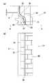
室炉式コークス炉(以下、単に「コークス炉」ともいう)の炉前面側の部分断面平面図を図1に示す。図1に示すように、室炉式コークス炉1は多数の燃焼室31と炭化室32とを交互に炉幅方向に配置し構成されている。そして、燃焼室31と炭化室32の炉体レンガ40は各種の金物によって表面を覆われて支持されている。これらの金物は炉体金物11と称されており、炭化室32の窯口10を形成するドアフレーム35、燃焼室31のレンガを押さえるプロテクションレッジ37およびプロテクションプレート38、ヘッドプレート34、フラッシュプレート33、フックボルト36、さらに燃焼室31や炭化室32の上部のレンガ40を押さえる上部ウォールプレート(図示せず)、同じく下部のレンガ40を押さえる下部ウォールプレート(図示せず)などからなっている。上記の炉体金物11の内、窯口10の近傍に配置されている金物(ドアフレーム35、プロテクションレッジ37、プロテクションプレート38、ヘッドプレート34、フラッシュプレート33、フックボルト36等)は窯口金物12と呼ばれている。通常の操業時においては、これらの炉体金物11をバックステー2が支持し、これを炉頂部や炉下部に配置したテンションロッド(図示せず)で締め付けて炉体3を保持している。 FIG. 1 shows a partial cross-sectional plan view of the front side of a chamber-type coke oven (hereinafter also simply referred to as “coke oven”). As shown in FIG. 1, the chamber-
ここで、図2に、室炉式コークス炉1の建設当時の健全な状態の窯口構造を示す。図2(a)が平面図であり、図2(b)が側面図(図2(a)のA−A矢視断面図)である。 Here, FIG. 2 shows a structure of the kiln mouth in a healthy state at the time of construction of the chamber furnace
ただし、室炉式コークス炉1では炭化室32と燃焼室31の部分の高さが8〜10m程度あり、また、この部分のレンガ40は石炭の炭化に必要な1000℃を超える高温を内部に保持するものであるから、炉体金物11の温度も高温となるため、長期間の操業の間に炉体金物11そのものの変形やバックステー2の変形が生じ、炉体金物11(特に、窯口金物12)が脱落し、炉体3の変形が進み、最終的には炉体レンガ40が崩れるという不具合が生じる場合がある。そして、現有するコークス炉1の寿命は40年を越えるものが多くなり、炉体3の変形、炉体レンガ40の損耗、炉体金物11の劣化が増加している。 However, in the chamber furnace
しかし、コークス炉1の建設には膨大な費用を必要とするため、コークス炉1の寿命の延長を図ることで費用削減を達成することが指向されている。このため、変形したバックステー2の交換や、緩みや脱落が生じた炉体金物11の補修や交換をすることにより炉体3の健全性を維持するようになってきた。 However, since the construction of the
コークス炉1の炉体金物11の緩みの多くは、部分的に破損して炭化室32側に張り出してくるもので、さらに悪化すれば炉体金物11が脱落するという問題が生ずる。このような場合、通常、炉体金物11が脱落した部位にモルタルを詰めるような補修を行うが、一時的な対策に過ぎず、状況は徐々に悪化していく。 Most of the looseness of the
図3に、炉体3が変形し、プロテクションレッジ37が脱落し、モルタル39を詰めて補修を行った窯口構造を示す。図3(a)が平面図であり、図3(b)が側面図(図3(a)のA−A矢視断面図)である。図3では、すべての個所でプロテクションレッジ37が脱落しており、その脱落部分にモルタル39を詰めて補修しているが、多くの場合、部分的にプロテクションレッジ37が脱落しており、プロテクションレッジ37が残存した部分とモルタル39で補修した部分が混在する。 FIG. 3 shows a kiln structure in which the
このような炉体3の異常の発生に対し、特許文献1には、バックステー2の交換時に緩んでいた炉体金物11を固定する技術が開示されている。 With respect to the occurrence of such an abnormality of the
従来、緩みや脱落が生じた炉体金物11の補修や交換を行う際には、バックステー2を外す必要があり、このような補修・交換作業を行うと、炉体全体の締め付け力が低下し、さらに炉体温度の低下を招き、補修・交換作業そのものによる炉体劣化のリスクが伴うという新たな問題が生ずる。また、バックステー2を外す作業は特許文献1に示されているように、非常に大掛かりなものとなり、そのための費用および修理に要する日数の増大という問題がある。また、図3に示したように、炉体全体が変形しているため、新しいバックステー2が上手く取り付けられないといった問題もある。 Conventionally, it is necessary to remove the
本発明は、上記のような事情に鑑みてなされたものであり、室炉式コークス炉の窯口構造として、操業によるコークス押出負荷や熱負荷の影響下でも、窯口金物に緩みや脱落が生じることを的確に防止できる窯口構造を提供することを目的とするものである。 The present invention has been made in view of the above circumstances, and as a kiln opening structure of a chamber type coke oven, the kiln fittings are loosened or dropped even under the influence of coke extrusion load or heat load due to operation. An object of the present invention is to provide a kiln structure that can accurately prevent the occurrence.
本発明者らは、窯口金物のうち、特にプロテクションレッジに注目し、そのプロテクションレッジが緩んだり脱落したりすることを防止するために鋭意検討を重ねた。その結果、プロテクションレッジの一部をヘッドプレートより炉前面側(炉の手前側)に位置させ、そのプロテクションレッジをヘッドプレートより炉前面側(炉の手前側)の位置で固定することが有効であることを見出した。 The inventors of the present invention have paid particular attention to the protection ledge among the kiln fittings, and have made extensive studies in order to prevent the protection ledge from loosening or falling off. As a result, it is effective to place a part of the protection ledge on the front side of the furnace (front side of the furnace) from the head plate and fix the protection ledge at a position on the front side of the furnace (front side of the furnace) from the head plate. I found out.
本発明は、上記の知見に基づいてなされており、以下のような特徴を備えている。 The present invention has been made based on the above findings and has the following features.
[1]燃焼室と炭化室とを交互に炉幅方向に配置して構成され、炭化室の窯口にドアフレームと、燃焼室のレンガを押さえるプロテクションレッジおよびヘッドプレートと、フラッシュプレートとを有する室炉式コークス炉において、プロテクションレッジでヘッドプレートを挟み込み、少なくとも前記プロテクションレッジの一部が前記ヘッドプレートより炉前面側に位置し、前記ヘッドプレートより炉前面側の位置で前記プロテクションレッジが固定されていることを特徴とするコークス炉の窯口構造。 [1] The combustion chamber and the carbonization chamber are alternately arranged in the furnace width direction, and have a door frame, a protection ledge and a head plate for holding the brick in the combustion chamber, and a flash plate at the furnace port of the carbonization chamber. In a chamber-type coke oven, a head plate is sandwiched between protection ledges, at least a part of the protection ledge is located on the front side of the furnace from the head plate, and the protection ledge is fixed at a position on the front side of the furnace from the head plate. Coke oven structure of the coke oven, characterized by
[2]前記プロテクションレッジは、凹凸部を有し、その凹凸部で他の金物と噛み合わされていることを特徴とする前記[1]に記載のコークス炉の窯口構造。 [2] The kiln structure of a coke oven according to [1], wherein the protection ledge has an uneven portion, and the uneven portion engages with other hardware.
[3]前記他の金物は、ヘッドプレートとドアフレームの間隔を調整するライナーであることを特徴とする前記[2]に記載のコークス炉の窯口構造。 [3] The coke oven furnace structure according to [2], wherein the other hardware is a liner that adjusts a distance between the head plate and the door frame.
[4]前記プロテクションレッジは、高さ方向に凸部を持つプロテクションレッジ部品と高さ方向に凹部を持つプロテクションレッジ部品とが噛み合わされて、高さ方向に2個以上のプロテクションレッジ部品が連ねられて構成されていることを特徴とする前記[1]〜[3]のいずれかに記載のコークス炉の窯口構造。 [4] In the protection ledge, a protection ledge component having a convex portion in the height direction and a protection ledge component having a concave portion in the height direction are engaged with each other, and two or more protection ledge components are connected in the height direction. The coke oven kiln structure according to any one of [1] to [3], wherein the structure is configured as described above.
本発明においては、プロテクションレッジの少なくとも一部がヘッドプレートより炉前面側(炉の手前側)に位置し、炉前面側(炉の手前側)からプロテクションレッジを固定するようにしたので、プロテクションレッジの緩みや脱落が防止でき、補修頻度や補修作業が低減し、炉体の保護が達成できるという利点がある。 In the present invention, at least a part of the protection ledge is located on the front side of the furnace (front side of the furnace) from the head plate, and the protection ledge is fixed from the front side of the furnace (front side of the furnace). Can be prevented from loosening and falling off, the frequency of repairs and repair work can be reduced, and the furnace body can be protected.
本発明の実施形態を図面に基づいて説明する。 Embodiments of the present invention will be described with reference to the drawings.
[実施形態1]
前述したように、図2は建設当時の健全な状態の窯口構造を示すものである。この窯口構造では、一定期間の使用を経過するとプロテクションレッジ37が炭化室32側に変形したり落下したりするような状態となり、窯口の補修が必要な状態になる。[Embodiment 1]
As described above, FIG. 2 shows a healthy kiln structure at the time of construction. In this kiln structure, after a certain period of use, the
そして、前述したように、図3は炉体3の変形と全てのプロテクションレッジ37の脱落が生じた状態の窯口構造を示すものである。この状態ではドアフレーム35が変形して、炉蓋が嵌らなくなる問題が発生し、しばしばドアフレーム35の交換が実施されている。 As described above, FIG. 3 shows a kiln structure in a state where the
図4に、ドアフレーム35を交換した場合の窯口構造を示す。図4(a)が平面図であり、図4(b)が側面図(図4(a)のA−A矢視断面図)である。新品ドアフレーム35の設置のため、ドアフレーム35と炉体3の変形部との隙間にはヤーンロープ41などの詰め物が入る他、ヘッドプレート34とドアフレーム35の間隔を調整するために、適切な厚みを持った鉄系部材のライナー42が取り付けられる場合もある。 FIG. 4 shows a kiln structure when the
本発明者らは、脱落したプロテクションレッジ37の部分にモルタル39を詰めるだけでは強度部材にならず、炉体3の変形が更に進んでしまうことと、単純にプロテクションレッジ37と同等の部材を入れ込むだけでは、すぐにその同等部材が脱落してしまうことを確認した。 The inventors of the present invention do not become a strength member simply by filling the part of the
また、プロテクションレッジ37の脱落を防止するために、プロテクションレッジ37をヘッドプレート34に固定することが考えられるが、燃焼室31の奥側にあるプロテクションレッジ37とヘッドプレート34の間で何らかの固定処理をすることは非常に困難であることも承知している。 In order to prevent the
そこで、本発明者らは、鋭意検討の結果、ドアフレーム35の交換時に炉前面側(炉の手前側)からプロテクションレッジ37を固定し、プロテクションレッジ37の脱落を防止することが可能であることを見出した。 Therefore, as a result of intensive studies, the present inventors are able to fix the
上記の知見に基づく、本発明の実施形態1における窯口構造を図5に示す。図5(a)が平面図であり、図5(b)が側面図(図5(a)のA−A矢視断面図)である。 The kiln structure in
図5に示すように、この実施形態1においては、ドアフレーム35と炉体3の変形部との隙間にヤーンロープ41が入るとともに、ヘッドプレート34とドアフレーム35の間隔を調整する鉄系部材のライナー42が取り付けられている。そして、コの字形状をしたプロテクションレッジ43でヘッドプレート34を挟み込み、少なくともプロテクションレッジ43の一部がヘッドプレート34より炉前面側(炉の手前側)に位置し、ヘッドプレート34より炉前面側(炉の手前側)の位置でプロテクションレッジ43が溶接またはリベットでヘッドプレート34もしくはライナー42に固定されている。 As shown in FIG. 5, in the first embodiment, the
ちなみに、ヘッドプレート34は燃焼室31の幅方向左右にわたって設けられている部材であり、ヘッドプレート34あるいはそのヘッドプレート34に固定されているライナー42は、直接バックステー2で固定されているので、最も炭化室32方向に張り出しにくい部材である。したがって、そのようなヘッドプレート34もしくはライナー42にプロテクションレッジ43を固定することによって、プロテクションレッジ37の張り出し/脱落を的確に防止することができる。 Incidentally, the
なお、図5では、ライナー42の間に1個ずつプロテクションレッジ43が取り付けられているが、ライナー42の間に複数個のプロテクションレッジ43が取り付けられていても良いし、部分的にプロテクションレッジ43が取り付けられていない箇所があっても構わない。 In FIG. 5, the
また、当初のプロテクションレッジ37が残存している箇所では、そのまま当初のプロテクションレッジ37を採用しても構わない。 Further, the
また、劣化が進むと、プロテクションレッジ37だけでなく、プロテクションプレート38も脱落している場合がある。この場合はプロテクションプレート38の部分もカバーする寸法でプロテクションレッジ43を取り付けても良い。 Further, when the deterioration progresses, not only the
すなわち、プロテクションレッジ43は、ヘッドプレート34の炉前面側にプロテクションレッジ43の一部があり、溶接やリベット留などで固定できる形状であれば、コの字の形状でなくても構わない。 That is, the
このようにして、この実施形態1においては、プロテクションレッジ43の少なくとも一部がヘッドプレート34より炉前面側(炉の手前側)に位置し、炉前面側(炉の手前側)からプロテクションレッジ43を固定することができるので、プロテクションレッジ43の緩みや脱落が防止でき、補修頻度や補修作業が低減し、炉体3の保護が達成できるという利点がある。 In this way, in the first embodiment, at least a part of the
[実施形態2]
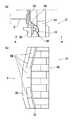
本発明の実施形態2における窯口構造を図6に示す。図6(a)が平面図、図6(b)が側面図(図6(a)のB−B矢視断面図)、図6(c)が部分斜視図である。[Embodiment 2]
The kiln structure in
この実施形態2における窯口構造は、上記の実施形態1における窯口構造と基本的には同様であるが、図6(c)に示すように、プロテクションレッジ44が、炉幅方向の凹部44aと、高さ方向の凹部44bを有しており、凹部44aでヘッドプレート34を挟み込むとともに、凹部44bでライナー42と噛み合わされている。 The kiln structure in the second embodiment is basically the same as the kiln structure in the first embodiment. However, as shown in FIG. 6 (c), the
これによって、この実施形態2においては、プロテクションレッジ44が他の金物(ここでは、ライナー42)と噛み合うことで、プロテクションレッジ44の脱落が一層防止でき、補修頻度や補修作業がさらに低減し、炉体3の保護が達成できるという利点がある。 Accordingly, in the second embodiment, the
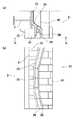
[実施形態3]
本発明の実施形態3における窯口構造を図7に示す。図7(a)が平面図、図7(b)が側面図(図7(a)のB−B矢視断面図)、図7(c)が部分斜視図である。[Embodiment 3]
The kiln structure in
この実施形態3における窯口構造は、上記の実施形態1における窯口構造と基本的には同様であるが、図7(b)に示すように、高さ方向に複数個(ここでは、3個)のプロテクションレッジ部品46が連ねられてプロテクションレッジ45が構成されている。このプロテクションレッジ部品46は、図7(c)に示すように、炉幅方向の凹部46aと、高さ方向の凸部46bと、高さ方向の凹部46cを有しており、凹部46aでヘッドプレート34を挟み込むとともに、凹部46cを他のプロテクションレッジ部品46の凸部46bと噛み合わせている。なお、最下方のプロテクションレッジ部品46は、凹部46cをライナー42に設けた凸部42aと噛み合わせている。 The kiln structure in the third embodiment is basically the same as the kiln structure in the first embodiment described above, but as shown in FIG. )
これによって、この実施形態3においては、プロテクションレッジ部品46が複数個(ここでは、3個)噛み合うことでプロテクションレッジ45が構成されているので、プロテクションレッジ45の脱落が一層防止でき、補修頻度や補修作業がさらに低減し、炉体3の保護が達成できるという利点がある。 Accordingly, in the third embodiment, the
ちなみに、プロテクションレッジ部品46を複数個組み合わしてプロテクションレッジ45を構成しているのは、次のような理由である。すなわち、プロテクションレッジ単体の高さ方向寸法が大きいと、炉体3が変形(湾曲)している場合は嵌め込むことが難しくなる。一方、炉体3の変形防止効果の点からは、プロテクションレッジができるだけ高さ方向全体にわたって嵌め込まれていることが望ましい。そこで、高さ方向寸法を短くしたプロテクションレッジ部品46を複数個組み合わせてプロテクションレッジ45を構成することで、嵌め込みの容易性(施工性)と炉体3の変形防止効果を両立できるようにしている。 Incidentally, the reason why the
本発明の実施例1を述べる。 A first embodiment of the present invention will be described.
この実施例1においては、表1に示す仕様のコークス炉を用いてコークスの製造を2ヶ月間行い、窯口構造の変形(窯口構造の変化・緩み、窯口金物の脱落)の状態を経時的に観察した。また、窯口構造の変形に伴うコークス押出負荷の変化も観察して、押出負荷からも窯口構造の変形を間接的に評価した。 In this Example 1, coke was manufactured for 2 months using a coke oven having the specifications shown in Table 1, and the state of deformation of the kiln structure (change / loosening of kiln structure, dropping of kiln hardware) Observed over time. Moreover, the change of the coke extrusion load accompanying the deformation of the kiln structure was also observed, and the deformation of the kiln structure was indirectly evaluated from the extrusion load.
その際に、図4に示した従来の窯口構造の場合を従来例とし、図5に示した本発明の実施形態1における窯口構造の場合を本発明例1、図6に示した本発明の実施形態2における窯口構造の場合を本発明例2、図7に示した本発明の実施形態3における窯口構造の場合を本発明例3とした。 At that time, the case of the conventional kiln structure shown in FIG. 4 is taken as a conventional example, and the case of the kiln structure in
なお、窯口構造の変形の状態については、それぞれの窯口構造を新規に設置した初期のプロテクションレッジの炭化室側への張出量をゼロとして、2ヶ月間の操業後のプロテクションレッジの炭化室側への張出量をレーザー変位計で測定した。従来例における張出量を1とした場合の本発明例1〜3における張出量の相対値を表2に示す。また、コークス押出負荷については、2ヶ月間の操業後の押出機にかかる電流値を測定し、従来例における押出負荷(電流値)を1とした場合の本発明例1〜3における押出負荷(電流値)の相対値を表2に示す。 Regarding the state of deformation of the kiln opening structure, the carbonization of the protection ledge after two months of operation was set to zero with the amount of overhang of the initial protection ledge where each kiln opening structure was newly installed to the coking chamber side being zero. The amount of overhang to the room side was measured with a laser displacement meter. Table 2 shows the relative values of the overhang amounts in Invention Examples 1 to 3 when the overhang amount in the conventional example is 1. Moreover, about the coke extrusion load, the electric current value concerning the extruder after the operation for two months is measured, and the extrusion load in the present invention examples 1 to 3 when the extrusion load (current value) in the conventional example is 1. The relative values of (current value) are shown in Table 2.
表2に示すように、従来例に比べて、本発明例1〜3ではプロテクションレッジの炭化室側への張出量は小さく、そのためコークス押出負荷も小さくなっている。また、本発明例1に比べて、本発明例2、3の方が張出量とコークス押出負荷が小さく、一層効果が大きいことが認められる。 As shown in Table 2, compared with the conventional example, in Examples 1 to 3 of the present invention, the overhang amount of the protection ledge toward the carbonization chamber is small, and therefore the coke extrusion load is also small. Further, it can be seen that, compared with Invention Example 1, Invention Examples 2 and 3 have a smaller overhang amount and coke extrusion load and are more effective.

1 室炉式コークス炉
2 バックステー
3 炉体
10 窯口
11 炉体金物
12 窯口金物
31 燃焼室
32 炭化室
33 フラッシュプレート
34 ヘッドプレート
35 ドアフレーム
36 フックボルト
37 プロテクションレッジ
38 プロテクションプレート
39 モルタル
40 レンガ
41 ヤーンロープ
42 ライナー
42a 凸部
43 プロテクションレッジ
44 プロテクションレッジ
44a 凹部
44b 凹部
45 プロテクションレッジ
46 プロテクションレッジ部品
46a 凹部
46b 凸部
46c 凹部DESCRIPTION OF
Claims (4)
Translated fromJapanesePriority Applications (1)
| Application Number | Priority Date | Filing Date | Title |
|---|---|---|---|
| JP2010254366AJP2012102302A (en) | 2010-11-15 | 2010-11-15 | Kiln mouth structure of coke oven |
Applications Claiming Priority (1)
| Application Number | Priority Date | Filing Date | Title |
|---|---|---|---|
| JP2010254366AJP2012102302A (en) | 2010-11-15 | 2010-11-15 | Kiln mouth structure of coke oven |
Publications (1)
| Publication Number | Publication Date |
|---|---|
| JP2012102302Atrue JP2012102302A (en) | 2012-05-31 |
Family
ID=46393060
Family Applications (1)
| Application Number | Title | Priority Date | Filing Date |
|---|---|---|---|
| JP2010254366AWithdrawnJP2012102302A (en) | 2010-11-15 | 2010-11-15 | Kiln mouth structure of coke oven |
Country Status (1)
| Country | Link |
|---|---|
| JP (1) | JP2012102302A (en) |
Cited By (45)
| Publication number | Priority date | Publication date | Assignee | Title |
|---|---|---|---|---|
| WO2014105066A1 (en)* | 2012-12-28 | 2014-07-03 | Suncoke Technology And Development Llc. | Coke oven doors having improved construction and insulation features and associated systems and methods |
| US9169439B2 (en) | 2012-08-29 | 2015-10-27 | Suncoke Technology And Development Llc | Method and apparatus for testing coal coking properties |
| US9193913B2 (en) | 2012-09-21 | 2015-11-24 | Suncoke Technology And Development Llc | Reduced output rate coke oven operation with gas sharing providing extended process cycle |
| US9193915B2 (en) | 2013-03-14 | 2015-11-24 | Suncoke Technology And Development Llc. | Horizontal heat recovery coke ovens having monolith crowns |
| US9200225B2 (en) | 2010-08-03 | 2015-12-01 | Suncoke Technology And Development Llc. | Method and apparatus for compacting coal for a coal coking process |
| US9238778B2 (en) | 2012-12-28 | 2016-01-19 | Suncoke Technology And Development Llc. | Systems and methods for improving quenched coke recovery |
| US9243186B2 (en) | 2012-08-17 | 2016-01-26 | Suncoke Technology And Development Llc. | Coke plant including exhaust gas sharing |
| US9249357B2 (en) | 2012-08-17 | 2016-02-02 | Suncoke Technology And Development Llc. | Method and apparatus for volatile matter sharing in stamp-charged coke ovens |
| US9273250B2 (en) | 2013-03-15 | 2016-03-01 | Suncoke Technology And Development Llc. | Methods and systems for improved quench tower design |
| US9273249B2 (en) | 2012-12-28 | 2016-03-01 | Suncoke Technology And Development Llc. | Systems and methods for controlling air distribution in a coke oven |
| US9359554B2 (en) | 2012-08-17 | 2016-06-07 | Suncoke Technology And Development Llc | Automatic draft control system for coke plants |
| US9476547B2 (en) | 2012-12-28 | 2016-10-25 | Suncoke Technology And Development Llc | Exhaust flow modifier, duct intersection incorporating the same, and methods therefor |
| US9580656B2 (en) | 2014-08-28 | 2017-02-28 | Suncoke Technology And Development Llc | Coke oven charging system |
| US9683740B2 (en) | 2012-07-31 | 2017-06-20 | Suncoke Technology And Development Llc | Methods for handling coal processing emissions and associated systems and devices |
| US10016714B2 (en) | 2012-12-28 | 2018-07-10 | Suncoke Technology And Development Llc | Systems and methods for removing mercury from emissions |
| US10047295B2 (en) | 2012-12-28 | 2018-08-14 | Suncoke Technology And Development Llc | Non-perpendicular connections between coke oven uptakes and a hot common tunnel, and associated systems and methods |
| JP2019038888A (en)* | 2017-08-23 | 2019-03-14 | 株式会社メガテック | Coke oven combustion chamber support structure |
| CN110094980A (en)* | 2019-05-28 | 2019-08-06 | 辽宁科技大学工程技术有限公司 | A kind of monoblock type protection board ontology with firedoor frame sealing function |
| US10526541B2 (en) | 2014-06-30 | 2020-01-07 | Suncoke Technology And Development Llc | Horizontal heat recovery coke ovens having monolith crowns |
| US10526542B2 (en) | 2015-12-28 | 2020-01-07 | Suncoke Technology And Development Llc | Method and system for dynamically charging a coke oven |
| US10619101B2 (en) | 2013-12-31 | 2020-04-14 | Suncoke Technology And Development Llc | Methods for decarbonizing coking ovens, and associated systems and devices |
| US10760002B2 (en) | 2012-12-28 | 2020-09-01 | Suncoke Technology And Development Llc | Systems and methods for maintaining a hot car in a coke plant |
| US10851306B2 (en) | 2017-05-23 | 2020-12-01 | Suncoke Technology And Development Llc | System and method for repairing a coke oven |
| US10883051B2 (en) | 2012-12-28 | 2021-01-05 | Suncoke Technology And Development Llc | Methods and systems for improved coke quenching |
| US10968393B2 (en) | 2014-09-15 | 2021-04-06 | Suncoke Technology And Development Llc | Coke ovens having monolith component construction |
| US10968395B2 (en) | 2014-12-31 | 2021-04-06 | Suncoke Technology And Development Llc | Multi-modal beds of coking material |
| US11008518B2 (en) | 2018-12-28 | 2021-05-18 | Suncoke Technology And Development Llc | Coke plant tunnel repair and flexible joints |
| US11021655B2 (en) | 2018-12-28 | 2021-06-01 | Suncoke Technology And Development Llc | Decarbonization of coke ovens and associated systems and methods |
| US11060032B2 (en) | 2015-01-02 | 2021-07-13 | Suncoke Technology And Development Llc | Integrated coke plant automation and optimization using advanced control and optimization techniques |
| US11071935B2 (en) | 2018-12-28 | 2021-07-27 | Suncoke Technology And Development Llc | Particulate detection for industrial facilities, and associated systems and methods |
| US11098252B2 (en) | 2018-12-28 | 2021-08-24 | Suncoke Technology And Development Llc | Spring-loaded heat recovery oven system and method |
| US11142699B2 (en) | 2012-12-28 | 2021-10-12 | Suncoke Technology And Development Llc | Vent stack lids and associated systems and methods |
| CN113503738A (en)* | 2021-07-07 | 2021-10-15 | 江苏苏盐井神股份有限公司 | Shaft kiln wall patching device in soda production |
| US11261381B2 (en) | 2018-12-28 | 2022-03-01 | Suncoke Technology And Development Llc | Heat recovery oven foundation |
| US11395989B2 (en) | 2018-12-31 | 2022-07-26 | Suncoke Technology And Development Llc | Methods and systems for providing corrosion resistant surfaces in contaminant treatment systems |
| US11486572B2 (en) | 2018-12-31 | 2022-11-01 | Suncoke Technology And Development Llc | Systems and methods for Utilizing flue gas |
| US11508230B2 (en) | 2016-06-03 | 2022-11-22 | Suncoke Technology And Development Llc | Methods and systems for automatically generating a remedial action in an industrial facility |
| US11760937B2 (en) | 2018-12-28 | 2023-09-19 | Suncoke Technology And Development Llc | Oven uptakes |
| US11767482B2 (en) | 2020-05-03 | 2023-09-26 | Suncoke Technology And Development Llc | High-quality coke products |
| US11788012B2 (en) | 2015-01-02 | 2023-10-17 | Suncoke Technology And Development Llc | Integrated coke plant automation and optimization using advanced control and optimization techniques |
| US11851724B2 (en) | 2021-11-04 | 2023-12-26 | Suncoke Technology And Development Llc. | Foundry coke products, and associated systems, devices, and methods |
| US11946108B2 (en) | 2021-11-04 | 2024-04-02 | Suncoke Technology And Development Llc | Foundry coke products and associated processing methods via cupolas |
| US12110458B2 (en) | 2022-11-04 | 2024-10-08 | Suncoke Technology And Development Llc | Coal blends, foundry coke products, and associated systems, devices, and methods |
| US12227699B2 (en) | 2019-12-26 | 2025-02-18 | Suncoke Technology And Development Llc | Oven health optimization systems and methods |
| US12410369B2 (en) | 2023-11-21 | 2025-09-09 | Suncoke Technology And Development Llc | Flat push hot car for foundry coke and associated systems and methods |
- 2010
- 2010-11-15JPJP2010254366Apatent/JP2012102302A/ennot_activeWithdrawn
Cited By (91)
| Publication number | Priority date | Publication date | Assignee | Title |
|---|---|---|---|---|
| US9200225B2 (en) | 2010-08-03 | 2015-12-01 | Suncoke Technology And Development Llc. | Method and apparatus for compacting coal for a coal coking process |
| US9683740B2 (en) | 2012-07-31 | 2017-06-20 | Suncoke Technology And Development Llc | Methods for handling coal processing emissions and associated systems and devices |
| US11441077B2 (en) | 2012-08-17 | 2022-09-13 | Suncoke Technology And Development Llc | Coke plant including exhaust gas sharing |
| US12195671B2 (en) | 2012-08-17 | 2025-01-14 | Suncoke Technology And Development Llc | Automatic draft control system for coke plants |
| US10947455B2 (en) | 2012-08-17 | 2021-03-16 | Suncoke Technology And Development Llc | Automatic draft control system for coke plants |
| US9243186B2 (en) | 2012-08-17 | 2016-01-26 | Suncoke Technology And Development Llc. | Coke plant including exhaust gas sharing |
| US10611965B2 (en) | 2012-08-17 | 2020-04-07 | Suncoke Technology And Development Llc | Coke plant including exhaust gas sharing |
| US11692138B2 (en) | 2012-08-17 | 2023-07-04 | Suncoke Technology And Development Llc | Automatic draft control system for coke plants |
| US9249357B2 (en) | 2012-08-17 | 2016-02-02 | Suncoke Technology And Development Llc. | Method and apparatus for volatile matter sharing in stamp-charged coke ovens |
| US9359554B2 (en) | 2012-08-17 | 2016-06-07 | Suncoke Technology And Development Llc | Automatic draft control system for coke plants |
| US10041002B2 (en) | 2012-08-17 | 2018-08-07 | Suncoke Technology And Development Llc | Coke plant including exhaust gas sharing |
| US10053627B2 (en) | 2012-08-29 | 2018-08-21 | Suncoke Technology And Development Llc | Method and apparatus for testing coal coking properties |
| US9169439B2 (en) | 2012-08-29 | 2015-10-27 | Suncoke Technology And Development Llc | Method and apparatus for testing coal coking properties |
| US9193913B2 (en) | 2012-09-21 | 2015-11-24 | Suncoke Technology And Development Llc | Reduced output rate coke oven operation with gas sharing providing extended process cycle |
| US11845037B2 (en) | 2012-12-28 | 2023-12-19 | Suncoke Technology And Development Llc | Systems and methods for removing mercury from emissions |
| US11008517B2 (en) | 2012-12-28 | 2021-05-18 | Suncoke Technology And Development Llc | Non-perpendicular connections between coke oven uptakes and a hot common tunnel, and associated systems and methods |
| US11939526B2 (en) | 2012-12-28 | 2024-03-26 | Suncoke Technology And Development Llc | Vent stack lids and associated systems and methods |
| US10016714B2 (en) | 2012-12-28 | 2018-07-10 | Suncoke Technology And Development Llc | Systems and methods for removing mercury from emissions |
| US12325828B2 (en) | 2012-12-28 | 2025-06-10 | Suncoke Technology And Development Llc | Exhaust flow modifier, duct intersection incorporating the same, and methods therefor |
| US10047295B2 (en) | 2012-12-28 | 2018-08-14 | Suncoke Technology And Development Llc | Non-perpendicular connections between coke oven uptakes and a hot common tunnel, and associated systems and methods |
| US10975309B2 (en) | 2012-12-28 | 2021-04-13 | Suncoke Technology And Development Llc | Exhaust flow modifier, duct intersection incorporating the same, and methods therefor |
| US9476547B2 (en) | 2012-12-28 | 2016-10-25 | Suncoke Technology And Development Llc | Exhaust flow modifier, duct intersection incorporating the same, and methods therefor |
| US9273249B2 (en) | 2012-12-28 | 2016-03-01 | Suncoke Technology And Development Llc. | Systems and methods for controlling air distribution in a coke oven |
| WO2014105066A1 (en)* | 2012-12-28 | 2014-07-03 | Suncoke Technology And Development Llc. | Coke oven doors having improved construction and insulation features and associated systems and methods |
| US10323192B2 (en) | 2012-12-28 | 2019-06-18 | Suncoke Technology And Development Llc | Systems and methods for improving quenched coke recovery |
| US11117087B2 (en) | 2012-12-28 | 2021-09-14 | Suncoke Technology And Development Llc | Systems and methods for removing mercury from emissions |
| US11142699B2 (en) | 2012-12-28 | 2021-10-12 | Suncoke Technology And Development Llc | Vent stack lids and associated systems and methods |
| US9862888B2 (en) | 2012-12-28 | 2018-01-09 | Suncoke Technology And Development Llc | Systems and methods for improving quenched coke recovery |
| US9238778B2 (en) | 2012-12-28 | 2016-01-19 | Suncoke Technology And Development Llc. | Systems and methods for improving quenched coke recovery |
| US11359145B2 (en) | 2012-12-28 | 2022-06-14 | Suncoke Technology And Development Llc | Systems and methods for maintaining a hot car in a coke plant |
| US10760002B2 (en) | 2012-12-28 | 2020-09-01 | Suncoke Technology And Development Llc | Systems and methods for maintaining a hot car in a coke plant |
| US10883051B2 (en) | 2012-12-28 | 2021-01-05 | Suncoke Technology And Development Llc | Methods and systems for improved coke quenching |
| US9193915B2 (en) | 2013-03-14 | 2015-11-24 | Suncoke Technology And Development Llc. | Horizontal heat recovery coke ovens having monolith crowns |
| US10927303B2 (en) | 2013-03-15 | 2021-02-23 | Suncoke Technology And Development Llc | Methods for improved quench tower design |
| US11746296B2 (en) | 2013-03-15 | 2023-09-05 | Suncoke Technology And Development Llc | Methods and systems for improved quench tower design |
| US9273250B2 (en) | 2013-03-15 | 2016-03-01 | Suncoke Technology And Development Llc. | Methods and systems for improved quench tower design |
| US11359146B2 (en) | 2013-12-31 | 2022-06-14 | Suncoke Technology And Development Llc | Methods for decarbonizing coking ovens, and associated systems and devices |
| US10619101B2 (en) | 2013-12-31 | 2020-04-14 | Suncoke Technology And Development Llc | Methods for decarbonizing coking ovens, and associated systems and devices |
| US10526541B2 (en) | 2014-06-30 | 2020-01-07 | Suncoke Technology And Development Llc | Horizontal heat recovery coke ovens having monolith crowns |
| US10308876B2 (en) | 2014-08-28 | 2019-06-04 | Suncoke Technology And Development Llc | Burn profiles for coke operations |
| US10920148B2 (en) | 2014-08-28 | 2021-02-16 | Suncoke Technology And Development Llc | Burn profiles for coke operations |
| US9580656B2 (en) | 2014-08-28 | 2017-02-28 | Suncoke Technology And Development Llc | Coke oven charging system |
| US11053444B2 (en) | 2014-08-28 | 2021-07-06 | Suncoke Technology And Development Llc | Method and system for optimizing coke plant operation and output |
| US9708542B2 (en) | 2014-08-28 | 2017-07-18 | Suncoke Technology And Development Llc | Method and system for optimizing coke plant operation and output |
| US10233392B2 (en) | 2014-08-28 | 2019-03-19 | Suncoke Technology And Development Llc | Method for optimizing coke plant operation and output |
| US9976089B2 (en) | 2014-08-28 | 2018-05-22 | Suncoke Technology And Development Llc | Coke oven charging system |
| US10968393B2 (en) | 2014-09-15 | 2021-04-06 | Suncoke Technology And Development Llc | Coke ovens having monolith component construction |
| US11795400B2 (en) | 2014-09-15 | 2023-10-24 | Suncoke Technology And Development Llc | Coke ovens having monolith component construction |
| US12338394B2 (en) | 2014-12-31 | 2025-06-24 | Suncoke Technology And Development Llc | Multi-modal beds of coking material |
| US10975311B2 (en) | 2014-12-31 | 2021-04-13 | Suncoke Technology And Development Llc | Multi-modal beds of coking material |
| US10975310B2 (en) | 2014-12-31 | 2021-04-13 | Suncoke Technology And Development Llc | Multi-modal beds of coking material |
| US10968395B2 (en) | 2014-12-31 | 2021-04-06 | Suncoke Technology And Development Llc | Multi-modal beds of coking material |
| US11060032B2 (en) | 2015-01-02 | 2021-07-13 | Suncoke Technology And Development Llc | Integrated coke plant automation and optimization using advanced control and optimization techniques |
| US11788012B2 (en) | 2015-01-02 | 2023-10-17 | Suncoke Technology And Development Llc | Integrated coke plant automation and optimization using advanced control and optimization techniques |
| US11214739B2 (en) | 2015-12-28 | 2022-01-04 | Suncoke Technology And Development Llc | Method and system for dynamically charging a coke oven |
| US10526542B2 (en) | 2015-12-28 | 2020-01-07 | Suncoke Technology And Development Llc | Method and system for dynamically charging a coke oven |
| US12190701B2 (en) | 2016-06-03 | 2025-01-07 | Suncoke Technology And Development Llc | Methods and systems for automatically generating a remedial action in an industrial facility |
| US11508230B2 (en) | 2016-06-03 | 2022-11-22 | Suncoke Technology And Development Llc | Methods and systems for automatically generating a remedial action in an industrial facility |
| US10851306B2 (en) | 2017-05-23 | 2020-12-01 | Suncoke Technology And Development Llc | System and method for repairing a coke oven |
| US11845898B2 (en) | 2017-05-23 | 2023-12-19 | Suncoke Technology And Development Llc | System and method for repairing a coke oven |
| JP2019038888A (en)* | 2017-08-23 | 2019-03-14 | 株式会社メガテック | Coke oven combustion chamber support structure |
| US11680208B2 (en) | 2018-12-28 | 2023-06-20 | Suncoke Technology And Development Llc | Spring-loaded heat recovery oven system and method |
| US11193069B2 (en) | 2018-12-28 | 2021-12-07 | Suncoke Technology And Development Llc | Coke plant tunnel repair and anchor distribution |
| US11643602B2 (en) | 2018-12-28 | 2023-05-09 | Suncoke Technology And Development Llc | Decarbonization of coke ovens, and associated systems and methods |
| US11505747B2 (en) | 2018-12-28 | 2022-11-22 | Suncoke Technology And Development Llc | Coke plant tunnel repair and anchor distribution |
| US11071935B2 (en) | 2018-12-28 | 2021-07-27 | Suncoke Technology And Development Llc | Particulate detection for industrial facilities, and associated systems and methods |
| US12060525B2 (en) | 2018-12-28 | 2024-08-13 | Suncoke Technology And Development Llc | Systems for treating a surface of a coke plant sole flue |
| US11760937B2 (en) | 2018-12-28 | 2023-09-19 | Suncoke Technology And Development Llc | Oven uptakes |
| US11008518B2 (en) | 2018-12-28 | 2021-05-18 | Suncoke Technology And Development Llc | Coke plant tunnel repair and flexible joints |
| US11597881B2 (en) | 2018-12-28 | 2023-03-07 | Suncoke Technology And Development Llc | Coke plant tunnel repair and flexible joints |
| US11365355B2 (en) | 2018-12-28 | 2022-06-21 | Suncoke Technology And Development Llc | Systems and methods for treating a surface of a coke plant |
| US12305119B2 (en) | 2018-12-28 | 2025-05-20 | Suncoke Technology And Development Llc | Decarbonization of coke ovens and associated systems and methods |
| US11845897B2 (en) | 2018-12-28 | 2023-12-19 | Suncoke Technology And Development Llc | Heat recovery oven foundation |
| US11261381B2 (en) | 2018-12-28 | 2022-03-01 | Suncoke Technology And Development Llc | Heat recovery oven foundation |
| US11098252B2 (en) | 2018-12-28 | 2021-08-24 | Suncoke Technology And Development Llc | Spring-loaded heat recovery oven system and method |
| US11021655B2 (en) | 2018-12-28 | 2021-06-01 | Suncoke Technology And Development Llc | Decarbonization of coke ovens and associated systems and methods |
| US11819802B2 (en) | 2018-12-31 | 2023-11-21 | Suncoke Technology And Development Llc | Methods and systems for providing corrosion resistant surfaces in contaminant treatment systems |
| US11395989B2 (en) | 2018-12-31 | 2022-07-26 | Suncoke Technology And Development Llc | Methods and systems for providing corrosion resistant surfaces in contaminant treatment systems |
| US11486572B2 (en) | 2018-12-31 | 2022-11-01 | Suncoke Technology And Development Llc | Systems and methods for Utilizing flue gas |
| CN110094980A (en)* | 2019-05-28 | 2019-08-06 | 辽宁科技大学工程技术有限公司 | A kind of monoblock type protection board ontology with firedoor frame sealing function |
| US12227699B2 (en) | 2019-12-26 | 2025-02-18 | Suncoke Technology And Development Llc | Oven health optimization systems and methods |
| US12215289B2 (en) | 2020-05-03 | 2025-02-04 | Suncoke Technology And Development Llc | High-quality coke products |
| US11767482B2 (en) | 2020-05-03 | 2023-09-26 | Suncoke Technology And Development Llc | High-quality coke products |
| CN113503738A (en)* | 2021-07-07 | 2021-10-15 | 江苏苏盐井神股份有限公司 | Shaft kiln wall patching device in soda production |
| US11946108B2 (en) | 2021-11-04 | 2024-04-02 | Suncoke Technology And Development Llc | Foundry coke products and associated processing methods via cupolas |
| US12319976B2 (en) | 2021-11-04 | 2025-06-03 | Suncoke Technology And Development Llc | Foundry coke products, and associated systems, devices, and methods |
| US11851724B2 (en) | 2021-11-04 | 2023-12-26 | Suncoke Technology And Development Llc. | Foundry coke products, and associated systems, devices, and methods |
| US12331367B2 (en) | 2021-11-04 | 2025-06-17 | Suncoke Technology And Development Llc | Foundry coke products, and associated systems, devices, and methods |
| US12110458B2 (en) | 2022-11-04 | 2024-10-08 | Suncoke Technology And Development Llc | Coal blends, foundry coke products, and associated systems, devices, and methods |
| US12286591B2 (en) | 2022-11-04 | 2025-04-29 | Suncoke Technology And Development Llc | Coal blends, foundry coke products, and associated systems, devices, and methods |
| US12410369B2 (en) | 2023-11-21 | 2025-09-09 | Suncoke Technology And Development Llc | Flat push hot car for foundry coke and associated systems and methods |
Similar Documents
| Publication | Publication Date | Title |
|---|---|---|
| JP2012102302A (en) | Kiln mouth structure of coke oven | |
| US8545752B2 (en) | Cooling plate for a metallurgical furnace | |
| JP5321187B2 (en) | Heat insulation box for hot repair of coke oven carbonization chamber and hot repair method for carbonization chamber | |
| JP5266538B2 (en) | Refurbishment method of free slope gutter | |
| JP2011088948A (en) | Oven mouth structure of coke oven and method for manufacturing coke | |
| JP2011122078A (en) | Oven outlet structure of coke oven and method for producing coke therewith | |
| US20140252198A1 (en) | Support structure with dissimilar metal welds | |
| JP2011121999A (en) | Oven outlet structure of coke oven and method for producing coke therewith | |
| KR20080036753A (en) | Blast Furnace Slewing Suit with Groove Frame Structure | |
| JP2015137291A (en) | Furnace casing hardware of coke oven | |
| US11225694B2 (en) | Cooling panel for metallurgical furnace | |
| JP2008207921A (en) | Rail fastening mechanism with wire spring clip | |
| CN102506046A (en) | Assembly component for steel mold of concrete product | |
| JP6200556B2 (en) | Stave protection device and installation method thereof | |
| US9039959B2 (en) | Cooling plate arrangement and method for installing cooling plates in a metallurgical furnace | |
| JP2022062697A (en) | Method for holding together adjacent incinerator grate bars, and arrangement of incinerator grate bars | |
| CN104085829B (en) | The goods fork locking gear of combination buckets | |
| KR101166241B1 (en) | Coke oven door | |
| JP5034727B2 (en) | Thermal insulation material for bricks not subject to repair during hot repair of coke oven | |
| JP5803968B2 (en) | Coke oven repair method and kiln frame thickness adjustment member | |
| JP5920579B2 (en) | Coke oven furnace body management method | |
| CN223434338U (en) | Cover plate assembly for coal mining machine | |
| JP7255216B2 (en) | Supports for pit lids and support structures for pit lids | |
| RU2521675C1 (en) | Bracket for profiles of hinged facade systems | |
| JP2021165345A (en) | Gas calorie prediction method for coke oven gas |
Legal Events
| Date | Code | Title | Description |
|---|---|---|---|
| RD03 | Notification of appointment of power of attorney | Free format text:JAPANESE INTERMEDIATE CODE: A7423 Effective date:20120321 | |
| RD04 | Notification of resignation of power of attorney | Free format text:JAPANESE INTERMEDIATE CODE: A7424 Effective date:20120327 | |
| A300 | Withdrawal of application because of no request for examination | Free format text:JAPANESE INTERMEDIATE CODE: A300 Effective date:20140204 |