JP2012100926A - Body cavity insertion instrument - Google Patents
Body cavity insertion instrumentDownload PDFInfo
- Publication number
- JP2012100926A JP2012100926AJP2010252847AJP2010252847AJP2012100926AJP 2012100926 AJP2012100926 AJP 2012100926AJP 2010252847 AJP2010252847 AJP 2010252847AJP 2010252847 AJP2010252847 AJP 2010252847AJP 2012100926 AJP2012100926 AJP 2012100926A
- Authority
- JP
- Japan
- Prior art keywords
- pulley
- unit
- wire
- bending
- moving unit
- Prior art date
- Legal status (The legal status is an assumption and is not a legal conclusion. Google has not performed a legal analysis and makes no representation as to the accuracy of the status listed.)
- Withdrawn
Links
Images


Classifications
- A—HUMAN NECESSITIES
- A61—MEDICAL OR VETERINARY SCIENCE; HYGIENE
- A61B—DIAGNOSIS; SURGERY; IDENTIFICATION
- A61B1/00—Instruments for performing medical examinations of the interior of cavities or tubes of the body by visual or photographical inspection, e.g. endoscopes; Illuminating arrangements therefor
- A61B1/00147—Holding or positioning arrangements
- A61B1/0016—Holding or positioning arrangements using motor drive units
- A—HUMAN NECESSITIES
- A61—MEDICAL OR VETERINARY SCIENCE; HYGIENE
- A61B—DIAGNOSIS; SURGERY; IDENTIFICATION
- A61B1/00—Instruments for performing medical examinations of the interior of cavities or tubes of the body by visual or photographical inspection, e.g. endoscopes; Illuminating arrangements therefor
- A61B1/005—Flexible endoscopes
- A61B1/0051—Flexible endoscopes with controlled bending of insertion part
- A61B1/0052—Constructional details of control elements, e.g. handles
- A—HUMAN NECESSITIES
- A61—MEDICAL OR VETERINARY SCIENCE; HYGIENE
- A61B—DIAGNOSIS; SURGERY; IDENTIFICATION
- A61B1/00—Instruments for performing medical examinations of the interior of cavities or tubes of the body by visual or photographical inspection, e.g. endoscopes; Illuminating arrangements therefor
- A61B1/005—Flexible endoscopes
- A61B1/0051—Flexible endoscopes with controlled bending of insertion part
- A61B1/0057—Constructional details of force transmission elements, e.g. control wires
Landscapes
- Health & Medical Sciences (AREA)
- Life Sciences & Earth Sciences (AREA)
- Surgery (AREA)
- Biomedical Technology (AREA)
- Medical Informatics (AREA)
- Optics & Photonics (AREA)
- Pathology (AREA)
- Radiology & Medical Imaging (AREA)
- Biophysics (AREA)
- Engineering & Computer Science (AREA)
- Physics & Mathematics (AREA)
- Heart & Thoracic Surgery (AREA)
- Nuclear Medicine, Radiotherapy & Molecular Imaging (AREA)
- Molecular Biology (AREA)
- Animal Behavior & Ethology (AREA)
- General Health & Medical Sciences (AREA)
- Public Health (AREA)
- Veterinary Medicine (AREA)
- Endoscopes (AREA)
- Instruments For Viewing The Inside Of Hollow Bodies (AREA)
Abstract
Translated fromJapaneseDescription
Translated fromJapanese本発明は、内視鏡、処置具等の体腔内に挿入して使用する体腔内挿入器具に関する。 The present invention relates to a body cavity insertion device used by being inserted into a body cavity such as an endoscope and a treatment tool.
内視鏡等の体腔内挿入器具は、湾曲動作を行う湾曲部を備える挿入部と、挿入部より基端方向側に設けられる操作部とを備える。操作部には、湾曲部の湾曲操作を入力する湾曲操作入力部が設けられている。操作部の内部には、プーリが設けられている。プーリには、一対のワイヤの基端が接続されている。それぞれのワイヤの先端は湾曲部に接続されている。湾曲部を湾曲させる際には、湾曲操作入力部で湾曲操作が入力されることにより、プーリが回転する。プーリが回転することにより、一方のワイヤが牽引され、他方のワイヤが弛緩される。それぞれのワイヤが牽引又は弛緩されることにより、湾曲部が湾曲される。 An intra-body-cavity insertion instrument such as an endoscope includes an insertion portion that includes a bending portion that performs a bending operation, and an operation portion that is provided on the proximal direction side of the insertion portion. The operation unit is provided with a bending operation input unit for inputting a bending operation of the bending unit. A pulley is provided inside the operation unit. A base end of a pair of wires is connected to the pulley. The tip of each wire is connected to the bending portion. When the bending portion is bent, the pulley is rotated by inputting a bending operation at the bending operation input portion. As the pulley rotates, one wire is pulled and the other wire is relaxed. As each wire is pulled or relaxed, the bending portion is bent.
このような体腔内挿入器具では、湾曲部が繰り返し湾曲されることにより、ワイヤに弛みが生じ、湾曲操作に対する湾曲部の湾曲特性が変化する。このため、ワイヤの張力を調整することは重要となる。特許文献1には、ワイヤの張力を調整する張力調整装置が開示されている。この張力調整装置では、挿入部から延設されるワイヤがローラに掛けられ、ワイヤの基端がプーリに接続されている。そして、ワイヤの延設方向についてローラの位置を調整することにより、ワイヤの張力を調整している。 In such an intra-body-cavity insertion instrument, the bending portion is repeatedly bent, so that the wire is slackened, and the bending characteristic of the bending portion with respect to the bending operation changes. For this reason, it is important to adjust the tension of the wire.
上記特許文献1の張力調整装置では、ローラの位置調整は手動により行われる。このため、ワイヤの張力を調整する作業が複雑化する。また、手動によりローラの位置を調整するため、ワイヤの張力を常に一定に調整することは、困難である。ワイヤの張力が変化することにより、湾曲操作に対する湾曲部の湾曲特性も変化する。このため、湾曲操作の操作性が低下してしまう。 In the tension adjusting device of
本発明は上記課題に着目してなされたものであり、その目的とするところは、複雑な作業を行うことなく、湾曲部を湾曲させるワイヤの張力を常に一定に調整することが可能な体腔内挿入器具を提供することにある。 The present invention has been made paying attention to the above-mentioned problems, and the object of the present invention is to be able to adjust the tension of the wire that bends the bending portion to be always constant without performing complicated work. It is to provide an insertion instrument.
上記目的を達成するため、本発明のある態様では、湾曲動作を行う湾曲部を備え、体腔内に挿入される挿入部と、前記挿入部より基端方向側に設けられる操作部と、先端が前記湾曲部に接続され、牽引又は弛緩されることにより前記湾曲部を湾曲させるワイヤと、前記ワイヤの基端が接続され、回転軸を中心に回転することにより前記ワイヤを牽引又は弛緩するプーリを備え、前記操作部に自重により移動可能な状態で設けられる移動ユニットと、前記操作部に設けられ、前記移動ユニットの移動を規制する第1の作動状態と前記移動ユニットの移動を規制しない第2の作動状態との間で作動状態が変化する規制部と、を備える体腔内挿入器具を提供する。 In order to achieve the above object, according to an aspect of the present invention, an bending portion that performs a bending operation, an insertion portion that is inserted into a body cavity, an operation portion that is provided on a proximal side from the insertion portion, and a distal end are provided. A wire that is connected to the bending portion and that bends or relaxes to bend the bending portion and a base end of the wire that is connected and rotates around a rotation axis to pull or relax the wire. A moving unit that is provided in the operation unit so as to be movable by its own weight; a first operating state that is provided in the operation unit and restricts movement of the moving unit; and a second that does not restrict movement of the moving unit. A body cavity insertion device comprising: a restricting portion whose operating state changes between the operating state of
この体腔内挿入器具では、前記操作部は、前記湾曲部の湾曲操作を入力する湾曲操作入力部を備え、前記移動ユニットは、前記湾曲操作入力部と電気的に導通し、前記湾曲操作入力部での前記湾曲操作により回転する駆動部材と、前記駆動部材の回転を前記プーリに伝達する回転伝達部とを備えてもよい。この場合、前記プーリは、前記ワイヤの基端方向側の部位での延設方向に平行で、かつ、前記プーリの前記回転軸に直交する移動軸に沿って移動し、前記駆動部材は、前記駆動部材の回転軸が前記プーリの前記移動軸と一致することが好ましい。 In this intra-body-cavity insertion instrument, the operation unit includes a bending operation input unit that inputs a bending operation of the bending unit, and the moving unit is electrically connected to the bending operation input unit, and the bending operation input unit A drive member that is rotated by the bending operation at a position, and a rotation transmission unit that transmits the rotation of the drive member to the pulley. In this case, the pulley moves along a movement axis that is parallel to the extending direction at the proximal end side of the wire and perpendicular to the rotation axis of the pulley, and the drive member is It is preferable that the rotating shaft of the driving member coincides with the moving shaft of the pulley.
また、前記移動ユニットは、前記湾曲部の湾曲操作を入力する湾曲操作入力部と、前記湾曲操作入力部での前記湾曲操作を前記プーリに伝達し、前記プーリを回転させる伝達部材とを備えてもよい。 The moving unit includes a bending operation input unit that inputs a bending operation of the bending unit, and a transmission member that transmits the bending operation at the bending operation input unit to the pulley and rotates the pulley. Also good.
さらに、前記プーリは、前記ワイヤの基端方向側の部位での延設方向に平行で、かつ、前記プーリの前記回転軸に直交する移動軸に沿って移動し、前記移動ユニットは、前記プーリの前記移動軸上に重心が位置することが好ましい。 Further, the pulley moves along a moving axis that is parallel to an extending direction at a portion on the proximal end side of the wire and is orthogonal to the rotation axis of the pulley, and the moving unit includes the pulley It is preferable that the center of gravity is located on the moving axis.
本発明によれば、複雑な作業を行うことなく、湾曲部を湾曲させるワイヤの張力を常に一定に調整することが可能な体腔内挿入器具を提供することができる。 According to the present invention, it is possible to provide an intra-body-cavity insertion instrument that can always adjust the tension of a wire that bends a bending portion to be constant without performing complicated work.
(第1の実施形態)
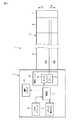
本発明の第1の実施形態について図1乃至図5を参照して説明する。図1及び図2は、体腔内挿入器具である内視鏡1を示す図である。図1に示すように、内視鏡1は、体腔内に挿入される挿入部2と、挿入部2より基端方向側に設けられる操作部3とを備える。操作部3には、ユニバーサルコード4の一端が接続されている。ユニバーサルコード4の他端は、スコープコネクタ(図示しない)を介して画像処理装置、光源装置等の外部装置(図示しない)に接続されている。(First embodiment)
A first embodiment of the present invention will be described with reference to FIGS. FIG.1 and FIG.2 is a figure which shows the
挿入部2は、細長い可撓管部5と、可撓管部5より先端方向側に設けられ、湾曲動作を行う湾曲部6と、湾曲部6より先端方向側に設けられる先端硬性部7とを備える。先端硬性部7には被写体の撮像を行う撮像素子(図示しない)等が設けられている。 The
操作部3は、外装である操作部ケーシング10と、湾曲部6の湾曲操作を入力する湾曲操作入力部であるジョイスティック8とを備える。また、操作部3には、電磁クラッチ13(図2参照)の操作を入力する規制操作入力部であるクラッチ操作ボタン9が設けられている。 The
図2に示すように、ジョイスティック8及びクラッチ操作ボタン9は、操作部3の内部に設けられる制御部11に電気的に接続されている。操作部3の内部には、自重により移動可能な移動ユニット15と、移動ユニット15の移動を規制する規制部である電磁クラッチ13とが設けられている。移動ユニット15は、駆動部材であるモータ16を備える。制御部11は、電磁クラッチ13及び移動ユニット15のモータ16に電気的に接続されている。このような構成であるため、湾曲操作入力部であるジョイスティック8と駆動部材であるモータ16との間が電気的に導通する。また、規制操作入力部であるクラッチ操作ボタン9と規制部である電磁クラッチ13との間が電気的に導通する。 As shown in FIG. 2, the
図3及び図4は、操作部3の内部の構成を示す図である。図3に示すように、操作部3の内部には、支持部材21及び支持部材22が操作部ケーシング10に固定された状態で設けられている。また、操作部ケーシング10の内部には、フレーム23及びフレーム24が、支持部材21及び支持部材22に固定された状態で設けられている。 3 and 4 are diagrams showing an internal configuration of the
移動ユニット15は、図3の矢印A1又は矢印A2の方向に移動可能な状態でフレーム24に取り付けられている。移動ユニット15は、モータ16と、ギアボックス17とを備える。また、移動ユニット15は、モータ16に連結される第1のギア25と、第1のギア25と噛合する第2のギア26と、第2のギア26に連結されるプーリ27とを備える。第1のギア25、第2のギア26及びプーリ27は、ギアボックス17の内部に設けられている。第1のギア25は、モータ16と同軸に設けられている。第2のギア26及びプーリ27は互いに同軸に設けられ、モータ16の軸に対して垂直な軸回りに回転可能に設けられる。このような構成のため、モータ16が駆動され、回転することにより、第1のギア25及び第2のギア26が回転する。そして、プーリ27がモータ16の軸に対して垂直な軸回りに回転する。すなわち、第1のギア25及び第2のギア26は、モータ16の回転をプーリ27に伝達する回転伝達部となっている。 The moving
プーリ27には、第1のワイヤ28A及び第2のワイヤ28Bの基端が接続されている。支持部材21には、滑車29が固定されている。第1のワイヤ28A及び第2のワイヤ28Bは、滑車29に掛けられ、操作部3の内部から挿入部2の内部へと延設されている。可撓管部5の内部では、第1のワイヤ28Aは、第1のコイルパイプ31Aに挿通されている。同様に、可撓管部5の内部では、第2のワイヤ28Bは、第2のコイルパイプ31Bに挿通されている。フレーム23には、第1のコイルパイプ31Aの基端が接続されるコイル止め32Aと、第2のコイルパイプ31Bの基端が接続されるコイル止め32Bとが固定されている。図2に示すように、第1のワイヤ28A及び第2のワイヤ28Bの先端は、湾曲部6に接続されている。このような構成のため、プーリ27が回転方向の一方に回転することにより、第1のワイヤ28Aが牽引され、第2のワイヤ28Bが弛緩される。これにより、湾曲部6が図2の矢印B1の方向に湾曲する。一方、プーリ27が回転方向の他方に回転することにより、第1のワイヤ28Aが弛緩され、第2のワイヤ28Bが牽引される。これにより、湾曲部6が図2の矢印B2の方向に湾曲する。 To the
図3に示すように、規制部である電磁クラッチ13は、操作部ケーシング10に取り付けられている。電磁クラッチ13は、クラッチ操作ボタン9でのクラッチ操作(規制操作)に対応して、移動ユニット15の移動を規制する第1の作動状態(図3の実線で示す状態)と移動ユニット15の移動を規制しない第2の作動状態(図3の点線で示す状態)との間で作動状態が変化する(図3の矢印C1及び矢印C2)。第1の作動状態では、電磁クラッチ13は、移動ユニット15のギアボックス17をフレーム24に向けて押圧する。これにより、移動ユニット15が電磁クラッチ13とフレーム24との間で挟持され、移動ユニット15の移動が規制される。一方、第2の作動状態では、電磁クラッチ13は、移動ユニット15に接触せず、移動ユニット15の移動を規制しない。このため、移動ユニット15は自重により図3の矢印A1の方向に移動する。 As shown in FIG. 3, the electromagnetic clutch 13 that is a restricting portion is attached to the
次に、本実施形態の内視鏡1の作用について説明する。内視鏡1では、湾曲操作入力部であるジョイスティック8での湾曲操作により、駆動部材であるモータ16が駆動され、回転する。モータ16が回転することにより、第1のギア25及び第2のギア26を介してプーリ27が回転する。プーリ27が回転方向の一方に回転することにより、第1のワイヤ28Aが牽引され、第2のワイヤ28Bが弛緩される。これにより、湾曲部6が図2の矢印B1の方向に湾曲する。一方、プーリ27が回転方向の他方に回転することにより、第1のワイヤ28Aが弛緩され、第2のワイヤ28Bが牽引される。これにより、湾曲部6が図2の矢印B2の方向に湾曲する。 Next, the operation of the
図5は、第1のワイヤ28A及び第2のワイヤ28Bの張力を調整する方法を示すフローチャートである。湾曲部6を湾曲させる際は、電磁クラッチ13は第1の作動状態に作動され、移動ユニット15の移動は規制されている。第1のワイヤ28A及び第2のワイヤ28Bの張力を調整する際には、規制操作入力部であるクラッチ操作ボタン9を押圧する(ステップS101)。そして、制御部11がクラッチ操作ボタン9でのクラッチ操作を電気信号として検出する(ステップS102)。そして、電気信号が制御部11から規制部である電磁クラッチ13に送信される(ステップ103)。電磁クラッチ13は、制御部11から電気信号を受信することにより、第1の作動状態から第2の作動状態に作動状態が変化する(ステップS104)。これにより、電磁クラッチ13が移動ユニット15の移動を規制せず、移動ユニット15が自重により図3の矢印A1の方向に移動する(ステップS105)。移動ユニット15の移動により、移動ユニット15のプーリ27に基端が接続される第1のワイヤ28A及び第2のワイヤ28Bの張力が調整される(ステップS106)。この際、移動ユニット15の質量は一定であるため、第1のワイヤ28A及び第2のワイヤ28Bは、常に一定の張力に調整される。 FIG. 5 is a flowchart showing a method of adjusting the tension of the
第1のワイヤ28A及び第2のワイヤ28Bが一定の張力に調整されると、クラッチ操作ボタン9の押圧をやめる(ステップS107)。そして、制御部11がクラッチ操作ボタン9でのクラッチ操作を電気信号として検出する(ステップS108)。そして、電気信号が制御部11から規制部である電磁クラッチ13に送信される(ステップ109)。電磁クラッチ13は、制御部11から電気信号を受信することにより、第2の作動状態から第1の作動状態に作動状態が変化する(ステップS110)。これにより、電磁クラッチ13は、移動ユニット15のギアボックス17をフレーム24に向けて押圧する。そして、移動ユニット15が電磁クラッチ13とフレーム24との間で挟持され、移動ユニット15の移動が規制される(ステップS111)。 When the
そこで上記構成の内視鏡1では、以下の効果を奏する。すなわち、本実施形態の内視鏡1では、規制部である電磁クラッチ13が第2の作動状態の際に、電磁クラッチ13は移動ユニット15の移動を規制しない。このため、移動ユニット15が自重により移動し、移動ユニット15のプーリ27に基端が接続される第1のワイヤ28A及び第2のワイヤ28Bの張力が調整される。この際、移動ユニット15の質量は一定であるため、第1のワイヤ28A及び第2のワイヤ28Bは、常に一定の張力に調整される。以上のようにして、複雑な作業を行うことなく、湾曲部6を湾曲させる第1のワイヤ28A及び第2のワイヤ28Bの張力を常に一定に調整することができる。 Therefore, the
また、内視鏡1では、移動ユニット15は、湾曲操作入力部であるジョイスティック8での湾曲操作により回転するモータ16と、回転することにより第1のワイヤ28A及び第2のワイヤ28Bを牽引又は弛緩するプーリ27と、モータ16の回転をプーリ27に伝達する回転伝達部である第1のギア25及び第2のギア26と、第1のギア25、第2のギア26及びプーリ27を収容するギアボックス17とを備える。すなわち、移動ユニット15は、湾曲部6を湾曲させるために必要な部材から構成されている。このため、第1のワイヤ28A及び第2のワイヤ28Bの張力を調整するために、例えば錘を別途設ける必要はない。したがって、操作部3の内部の構成の単純化、及び、内視鏡1の小型化を図ることができる。 In the
(第1の実施形態の変形例)
第1の実施形態では、規制操作入力部であるクラッチ操作ボタン9を押圧することにより電磁クラッチ13が第2の作動状態に変化し、クラッチ操作ボタン9を押圧しない状態で電磁クラッチ13が第1の作動状態に変化するが、これに限るものではない。例えば、規制操作入力部として、2つのクラッチ操作ボタンが設けられてもよい。この場合、2つのクラッチ操作ボタンの一方を押圧することにより、電磁クラッチ13は第1の作動状態に変化する。また、2つのクラッチ操作ボタンの他方を押圧することにより、電磁クラッチ13は第2の作動状態に変化する。(Modification of the first embodiment)
In the first embodiment, the
(第2の実施形態)
次に、本発明の第2の実施形態について、図6及び図7を参照して説明する。なお、第1の実施形態と同一の部分及び同一の機能を有する部分については同一の符号を付して、その説明は省略する。(Second Embodiment)
Next, a second embodiment of the present invention will be described with reference to FIGS. In addition, the same code | symbol is attached | subjected about the part which has the same function as 1st Embodiment, and the same function, and the description is abbreviate | omitted.
図6及び図7は、本実施形態の操作部3の内部の構成を示す図である。図6及び図7に示すように、操作部3には、自重により移動可能な移動ユニット40と、移動ユニット40の移動を規制する規制部である固定つまみ41とが設けられている。移動ユニット40は、図6の矢印A1の方向又は矢印A2の方向に移動可能にフレーム24に取り付けられている。移動ユニット40は、第1の実施形態と同様に、プーリ27を備える。プーリ27には、第1のワイヤ28A及び第2のワイヤ28Bの基端が接続されている。移動ユニット40は、フレーム24に移動可能に取り付けられる移動フレーム42を備える。また、移動ユニット40は、湾曲操作入力部であるアングルノブ43と、アングルノブ43での湾曲操作をプーリ27に伝達し、プーリ27を回転させる伝達部材45とを備える。伝達部材45は、プーリ27の軸回り方向に回転可能な状態で移動フレーム42に取り付けられている。このような構成のため、アングルノブ43での湾曲操作により、伝達部材45を介してプーリ27が回転する。 6 and 7 are diagrams illustrating an internal configuration of the
図6に示すように、規制部である固定つまみ41は、操作部ケーシング10に取り付けられている。固定つまみ41は、術者の操作により、移動ユニット40の移動を規制する第1の作動状態(図6の実線で示す状態)と移動ユニット40の移動を規制しない第2の作動状態(図6の点線で示す状態)との間で作動状態が変化する(図6の矢印C1及び矢印C2)。第1の作動状態では、固定つまみ41は、移動ユニット40の移動フレーム42に接触し、移動フレーム42を係止する。これにより、移動ユニット40の移動が規制される。一方、第2の作動状態では、固定つまみ41は、移動ユニット40に接触せず、移動ユニット40の移動を規制しない。このため、移動ユニット40は自重により図6の矢印A1の方向に移動する。 As shown in FIG. 6, the fixed
次に、本実施形態の内視鏡1の作用について説明する。内視鏡1では、湾曲部6を湾曲させる際は、固定つまみ41は第1の作動状態に作動され、移動ユニット40の移動は規制されている。第1のワイヤ28A及び第2のワイヤ28Bの張力を調整する際には、術者の操作により、固定つまみ41を第1の作動状態から第2の作動状態に変化させる。これにより、固定つまみ41が移動ユニット40の移動を規制せず、移動ユニット40が自重により図6の矢印A1の方向に移動する。移動ユニット40の移動により、移動ユニット40のプーリ27に基端が接続される第1のワイヤ28A及び第2のワイヤ28Bの張力が調整される。この際、移動ユニット40の質量は一定であるため、第1のワイヤ28A及び第2のワイヤ28Bは、常に一定の張力に調整される。 Next, the operation of the
第1のワイヤ28A及び第2のワイヤ28Bが一定の張力に調整されると、術者の操作により、固定つまみ41を第2の作動状態から第1の作動状態に変化させる。これにより、固定つまみ41は、移動ユニット40の移動フレーム42に接触し、移動フレーム42を係止する。そして、移動ユニット40の移動が規制される。 When the
そこで上記構成の内視鏡1では、以下の効果を奏する。すなわち、本実施形態の内視鏡1では、規制部である固定つまみ41が第2の作動状態の際に、固定つまみ41は移動ユニット40の移動を規制しない。このため、移動ユニット40が自重により移動し、移動ユニット40のプーリ27に基端が接続される第1のワイヤ28A及び第2のワイヤ28Bの張力が調整される。この際、移動ユニット40の質量は一定であるため、第1のワイヤ28A及び第2のワイヤ28Bは、常に一定の張力に調整される。以上のようにして、複雑な作業を行うことなく、湾曲部6を湾曲させる第1のワイヤ28A及び第2のワイヤ28Bの張力を常に一定に調整することができる。 Therefore, the
また、内視鏡1では、移動ユニット40は、湾曲操作入力部であるアングルノブ43と、回転することにより第1のワイヤ28A及び第2のワイヤ28Bを牽引又は弛緩するプーリ27と、アングルノブ43での湾曲操作をプーリに伝達する伝達部材45と、伝達部材が取り付けられる移動フレーム42とを備える。すなわち、移動ユニット40は、湾曲部6を湾曲させるために必要な部材から構成されている。このため、第1のワイヤ28A及び第2のワイヤ28Bの張力を調整するために、例えば錘を別途設ける必要はない。したがって、操作部3の内部の構成の単純化、及び、内視鏡1の小型化を図ることができる。 In the
(第3の実施形態)
次に、本発明の第3の実施形態について、図8及び図9を参照して説明する。なお、第1の実施形態と同一の部分及び同一の機能を有する部分については同一の符号を付して、その説明は省略する。(Third embodiment)
Next, a third embodiment of the present invention will be described with reference to FIGS. In addition, the same code | symbol is attached | subjected about the part which has the same function as 1st Embodiment, and the same function, and the description is abbreviate | omitted.
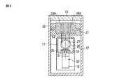
図8及び図9は、本実施形態の操作部3の内部の構成を示す図である。図8に示すように、操作部3の内部には、自重により移動可能な移動ユニット50と、移動ユニット50の移動を規制する規制部である電磁クラッチ13とが設けられている。移動ユニット50は、フレーム24に矢印A1又は矢印A2の方向に移動可能に取り付けられている。すなわち、本実施形態では、第1の実施形態の移動ユニット15と異なり、モータ16が支持部材21ではなくフレーム24に取り付けられている。なお、モータ16の回転を第1のギア25及び第2のギア26を介してプーリ27に伝達する構成は、第1の実施形態の移動ユニット15と同様である。 8 and 9 are diagrams illustrating an internal configuration of the
図8及び図9に示すように、プーリ27と滑車29との間での第1のワイヤ28A及び第2のワイヤ28Bの延設方向に平行で、かつ、プーリ27の回転軸S1に直交するプーリ27の移動軸S2を規定する。すなわち、プーリ27は、第1のワイヤ28A及び第2のワイヤ28Bの基端方向側の部位での延設方向に平行で、かつ、プーリ27の回転軸S1に直交する移動軸S2に沿って移動する。ここで、移動ユニット50の重心Gは、プーリ27の移動軸S2上に位置している。 As shown in FIGS. 8 and 9, the
そこで上記構成の内視鏡1では、第1の実施形態と同様の効果に加えて、以下の効果を奏する。例えば移動ユニット50の重心Gがプーリ27の移動軸S2から外れた位置にある場合、移動ユニット50の移動時に回転モーメントが発生する。このため、回転モーメントにより第1のワイヤ28A及び第2のワイヤ28Bの基端が接続されるプーリ27の移動が妨げられる。しかし、本実施形態の内視鏡1では、移動ユニット50の重心Gは、プーリ27の移動軸S2上に位置している。このため、移動ユニット50の移動時に回転モーメントが発生せず、プーリ27の移動が妨げられない。したがって、第1のワイヤ28A及び第2のワイヤ28Bの張力を調整する操作の操作性を向上させることができる。 Therefore, in addition to the same effects as those of the first embodiment, the
(第3の実施形態の変形例)
図10は、第3の実施形態の変形例に係る内視鏡1の操作部3の内部の構成を示す図である。図10に示すように、本変形例では、プーリ27の移動軸S2がモータ16の回転軸S3に一致している。移動ユニット50の中で、モータ16が最も質量が大きい部材である。このため、プーリ27の移動軸S2をモータ16の回転軸S3と一致させることにより、第3の実施形態とほぼ同様の効果を奏する。すなわち、移動ユニット50の移動時に回転モーメントが発生せず、プーリ27の移動が妨げられない。(Modification of the third embodiment)
FIG. 10 is a diagram illustrating an internal configuration of the
(その他の変形例)
第1の実施形態及び第3の実施形態では、移動ユニット15,50は、モータ16と、第1のギア25と、第2のギア26と、プーリ27と、ギアボックス17とを備え、第2の実施形態では、移動ユニット40は、アングルノブ43と、プーリ27と、伝達部材45と、移動フレーム42とを備えるが、これに限るものではない。すなわち、移動ユニット(15,40,50)は、第1のワイヤ28A及び第2のワイヤ28Bの基端が接続され、回転動作によって第1のワイヤ28A及び第2のワイヤ28Bを牽引又は弛緩するプーリ27を備えればよい。(Other variations)
In the first embodiment and the third embodiment, the moving
また、上述の実施形態では、湾曲部6は、2方向に湾曲する構成であるが、これに限るものではない。例えば、湾曲部6が4方向に湾曲する場合も、上述のワイヤ(28A,28B)の張力を調整する構成を適用可能である。 In the above-described embodiment, the bending portion 6 is configured to bend in two directions, but is not limited thereto. For example, even when the bending portion 6 is bent in four directions, a configuration for adjusting the tension of the wires (28A, 28B) described above can be applied.
さらに、上述の実施形態では、体腔内挿入器具として内視鏡1を例に挙げて説明したが、これに限るものではない。例えば、挿入部に湾曲部が設けられた処置具、マニピュレータ等でも、上述のワイヤ(28A,28B)の張力を調整する構成を適用可能である。 Furthermore, in the above-described embodiment, the
以上、本発明の実施形態について説明したが、本発明は上記の実施形態に限定されるものではなく、本発明の要旨を逸脱しない範囲で種々の変形ができることは勿論である。 The embodiments of the present invention have been described above. However, the present invention is not limited to the above-described embodiments, and various modifications can be made without departing from the scope of the present invention.
1…内視鏡、2…挿入部、3…操作部、6…湾曲部、13…電磁クラッチ、15…移動ユニット、27…プーリ、28A…第1のワイヤ、28B…第2のワイヤ。 DESCRIPTION OF
Claims (5)
Translated fromJapanese前記挿入部より基端方向側に設けられる操作部と、
先端が前記湾曲部に接続され、牽引又は弛緩されることにより前記湾曲部を湾曲させるワイヤと、
前記ワイヤの基端が接続され、回転軸を中心に回転することにより前記ワイヤを牽引又は弛緩するプーリを備え、前記操作部に自重により移動可能な状態で設けられる移動ユニットと、
前記操作部に設けられ、前記移動ユニットの移動を規制する第1の作動状態と前記移動ユニットの移動を規制しない第2の作動状態との間で作動状態が変化する規制部と、
を具備する体腔内挿入器具。An insertion portion that includes a bending portion that performs a bending operation, and is inserted into a body cavity;
An operation portion provided on the proximal direction side from the insertion portion;
A wire whose end is connected to the bending portion and bent or relaxed to bend the bending portion;
A moving unit that is connected to the proximal end of the wire and includes a pulley that pulls or loosens the wire by rotating around a rotation axis;
A regulating unit provided in the operation unit, the operating state changing between a first operating state that restricts movement of the moving unit and a second operating state that does not restrict movement of the moving unit;
A body cavity insertion device.
前記移動ユニットは、前記湾曲操作入力部と電気的に導通し、前記湾曲操作入力部での前記湾曲操作により回転する駆動部材と、前記駆動部材の回転を前記プーリに伝達する回転伝達部とを備える請求項1の体腔内挿入器具。The operation unit includes a bending operation input unit that inputs a bending operation of the bending unit,
The moving unit includes a driving member that is electrically connected to the bending operation input unit and rotates by the bending operation at the bending operation input unit, and a rotation transmission unit that transmits the rotation of the driving member to the pulley. The intra-body-cavity insertion device according to claim 1.
前記駆動部材は、前記駆動部材の回転軸が前記プーリの前記移動軸と一致する請求項2の体腔内挿入器具。The pulley moves along a moving axis that is parallel to the extending direction at the proximal end portion of the wire and perpendicular to the rotation axis of the pulley,
The intra-body-cavity insertion device according to claim 2, wherein the drive member has a rotation axis of the drive member that coincides with the movement axis of the pulley.
前記移動ユニットは、前記プーリの前記移動軸上に重心が位置する請求項1の体腔内挿入器具。The pulley moves along a moving axis that is parallel to the extending direction at the proximal end portion of the wire and perpendicular to the rotation axis of the pulley,
The intra-body-cavity insertion instrument according to claim 1, wherein the moving unit has a center of gravity located on the moving axis of the pulley.
Priority Applications (1)
| Application Number | Priority Date | Filing Date | Title |
|---|---|---|---|
| JP2010252847AJP2012100926A (en) | 2010-11-11 | 2010-11-11 | Body cavity insertion instrument |
Applications Claiming Priority (1)
| Application Number | Priority Date | Filing Date | Title |
|---|---|---|---|
| JP2010252847AJP2012100926A (en) | 2010-11-11 | 2010-11-11 | Body cavity insertion instrument |
Publications (1)
| Publication Number | Publication Date |
|---|---|
| JP2012100926Atrue JP2012100926A (en) | 2012-05-31 |
Family
ID=46392087
Family Applications (1)
| Application Number | Title | Priority Date | Filing Date |
|---|---|---|---|
| JP2010252847AWithdrawnJP2012100926A (en) | 2010-11-11 | 2010-11-11 | Body cavity insertion instrument |
Country Status (1)
| Country | Link |
|---|---|
| JP (1) | JP2012100926A (en) |
Cited By (3)
| Publication number | Priority date | Publication date | Assignee | Title |
|---|---|---|---|---|
| WO2014123135A1 (en)* | 2013-02-05 | 2014-08-14 | オリンパスメディカルシステムズ株式会社 | Insertion device |
| US10441375B2 (en) | 2014-07-10 | 2019-10-15 | Olympus Corporation | Medical instrument and adjustment method of medical instrument |
| CN115299867A (en)* | 2022-08-22 | 2022-11-08 | 广州兰韵医疗科技有限公司 | Electronic ureter soft lens capable of measuring temperature in real time |
- 2010
- 2010-11-11JPJP2010252847Apatent/JP2012100926A/ennot_activeWithdrawn
Cited By (4)
| Publication number | Priority date | Publication date | Assignee | Title |
|---|---|---|---|---|
| WO2014123135A1 (en)* | 2013-02-05 | 2014-08-14 | オリンパスメディカルシステムズ株式会社 | Insertion device |
| US10194786B2 (en) | 2013-02-05 | 2019-02-05 | Olympus Corporation | Insertion device |
| US10441375B2 (en) | 2014-07-10 | 2019-10-15 | Olympus Corporation | Medical instrument and adjustment method of medical instrument |
| CN115299867A (en)* | 2022-08-22 | 2022-11-08 | 广州兰韵医疗科技有限公司 | Electronic ureter soft lens capable of measuring temperature in real time |
Similar Documents
| Publication | Publication Date | Title |
|---|---|---|
| JP6138071B2 (en) | Loosening correction mechanism, manipulator and manipulator system | |
| US8308633B2 (en) | Manipulator operation system | |
| JP5750623B2 (en) | Introduction device | |
| JP5500844B2 (en) | Endoscope | |
| JP5583860B2 (en) | Insertion device provided with operation input unit | |
| CN101642363B (en) | Active medical apparatus system | |
| JP5559996B2 (en) | Endoscope device, endoscope system, and operation method of endoscope device | |
| JP6001189B2 (en) | manipulator | |
| WO2015174139A1 (en) | Endoscope | |
| JP6116777B1 (en) | Bending operation device and endoscope | |
| JP6076556B1 (en) | Bending operation device and endoscope | |
| JP2009136566A (en) | Holding cable, observation apparatus and endoscope apparatus having the holding cable | |
| US20130047755A1 (en) | Bending operation apparatus | |
| JP4454956B2 (en) | Endoscope | |
| JP5096202B2 (en) | Endoscope system | |
| JP2004321697A (en) | Endoscope | |
| JP2012100926A (en) | Body cavity insertion instrument | |
| JP6465447B2 (en) | Endoscope manufacturing method | |
| KR101454322B1 (en) | Master Robot for Surgery Robot System | |
| EP2617347B1 (en) | Endoscope | |
| WO2015005095A1 (en) | Introduction device | |
| JPWO2014123135A1 (en) | Insertion device | |
| JP6063773B2 (en) | Insertion device | |
| JP6600118B2 (en) | Endoscope | |
| WO2021070389A1 (en) | Bending operation mechanism for endoscope |
Legal Events
| Date | Code | Title | Description |
|---|---|---|---|
| A300 | Withdrawal of application because of no request for examination | Free format text:JAPANESE INTERMEDIATE CODE: A300 Effective date:20140204 |