JP2012100733A - Endoscopic diagnostic apparatus - Google Patents
Endoscopic diagnostic apparatusDownload PDFInfo
- Publication number
- JP2012100733A JP2012100733AJP2010249469AJP2010249469AJP2012100733AJP 2012100733 AJP2012100733 AJP 2012100733AJP 2010249469 AJP2010249469 AJP 2010249469AJP 2010249469 AJP2010249469 AJP 2010249469AJP 2012100733 AJP2012100733 AJP 2012100733A
- Authority
- JP
- Japan
- Prior art keywords
- light
- image
- illumination
- distribution
- signal
- Prior art date
- Legal status (The legal status is an assumption and is not a legal conclusion. Google has not performed a legal analysis and makes no representation as to the accuracy of the status listed.)
- Withdrawn
Links
Images


Landscapes
- Instruments For Viewing The Inside Of Hollow Bodies (AREA)
- Endoscopes (AREA)
- Closed-Circuit Television Systems (AREA)
Abstract
Translated fromJapaneseDescription
Translated fromJapanese本発明は、内視鏡スコープの先端部の異なる位置に配置された2つの照明窓を有し、これら2つの照明窓から被検体に照射される照明光の配光分布の違いを補正する機能を有する内視鏡診断装置に関するものである。 The present invention has two illumination windows arranged at different positions of the distal end portion of the endoscope scope, and a function of correcting a difference in light distribution of illumination light irradiated on the subject from these two illumination windows The present invention relates to an endoscope diagnostic apparatus having
近年の医療分野では、電子内視鏡を用いた診断や治療が数多く行なわれている。電子内視鏡は、被検者の体腔内に挿入される細長の挿入部を備えており、この挿入部の先端にはCCDなどの撮像装置が内蔵されている。また、電子内視鏡は光源装置に接続されており、光源装置で発せられた光は、挿入部の先端から体腔内部に対して照射される。このように体腔内部に光が照射された状態で、体腔内の被検体組織が、挿入部の先端の撮像装置によって撮像される。撮像により得られた画像は、電子内視鏡に接続されたプロセッサ装置で各種処理が施された後、モニタに表示される。したがって、電子内視鏡を用いることによって、被検者の体腔内の画像をリアルタイムに確認することができるため、診断などを確実に行うことができる。 In the medical field in recent years, many diagnoses and treatments using an electronic endoscope have been performed. The electronic endoscope includes an elongated insertion portion that is inserted into the body cavity of a subject, and an imaging device such as a CCD is built in the distal end of the insertion portion. Further, the electronic endoscope is connected to the light source device, and the light emitted from the light source device is irradiated to the inside of the body cavity from the distal end of the insertion portion. Thus, the subject tissue in the body cavity is imaged by the imaging device at the distal end of the insertion portion in a state where the light is irradiated inside the body cavity. An image obtained by imaging is displayed on a monitor after various processing is performed by a processor device connected to the electronic endoscope. Therefore, by using an electronic endoscope, an image in the body cavity of the subject can be confirmed in real time, so that diagnosis and the like can be performed reliably.
光源装置には、波長が青色領域から赤色領域にわたる白色の広帯域光を発することができるキセノンランプなどの白色光光源が用いられている。体腔内の照射に白色の広帯域光を用いることで、撮像画像から被検体組織全体を把握することができる。しかしながら、広帯域光を照射したときに得られる撮像画像からは、被検体組織全体を大まかに把握することはできるものの、微細血管、深層血管、ピットパターン(腺口構造)、陥凹や隆起といった凹凸構造などの被検体組織は明瞭に観察することが難しいことがある。このような被検体組織に対しては、特定の波長範囲に制限した狭帯域光を照射することで、明瞭に観察できるようになることが知られている。また、狭帯域光を照射したときの画像データから、血管中の酸素飽和度など被検体組織に関する各種情報を取得し、その取得した情報を画像化させることが知られている。 As the light source device, a white light source such as a xenon lamp capable of emitting white broadband light whose wavelength ranges from a blue region to a red region is used. By using white broadband light for irradiation in the body cavity, the entire subject tissue can be grasped from the captured image. However, although it is possible to roughly grasp the entire subject tissue from the captured image obtained when irradiated with broadband light, the irregularities such as microvessels, deep blood vessels, pit patterns (gland opening structure), depressions and bumps It may be difficult to clearly observe a subject tissue such as a structure. It is known that such a subject tissue can be clearly observed by irradiating narrow band light limited to a specific wavelength range. In addition, it is known that various types of information related to a subject tissue such as oxygen saturation in blood vessels is acquired from image data when narrow band light is irradiated, and the acquired information is imaged.
例えば、特許文献1では、狭帯域光を用いて酸素飽和度画像を得るものとして、キセノンランプから発せられる広帯域光から、帯域制限フィルタにより、近赤外領域の3波長の狭帯域光(IR1,IR2,IR3)、または、可視光領域の3波長の狭帯域光(G1,G2,G3)を分離して、各狭帯域光の画像を面順次で取得する例が示されている。いずれの組み合わせも、血中ヘモグロビンの酸素飽和度に応じて光の吸収度(吸光度)が変化する波長範囲の2つの狭帯域光と変化しない波長範囲の1つの狭帯域光とを組み合わせたものになっている。また、特許文献1には、3波長の狭帯域光に対応する3つの信号のうち2つを選択し、その差を検出して酸素飽和度画像をモノクロあるいは疑似カラーで表示することが記載されている。 For example, in
また、所定の波長範囲の励起光(狭帯域光)を被検体の被観察領域に照射することにより、被検体から発せられる自家蛍光を撮像素子で撮像して自家蛍光画像を取得し、モニタ画面上に表示する蛍光内視鏡装置が知られている。例えば、特許文献2には、生体組織の自家蛍光を観察する電子内視鏡プロセッサであって、白色光と励起光を交互に照射し、白色光画像を参照画像として、参照画像の画像データと蛍光画像の画像データとの差分を算出して患部画像データを抽出し、参照画像の画像データと患部画像データを合成することにより、病変部における蛍光の減衰を観察しやすくする方法が記載されている。 In addition, by irradiating the observation region of the subject with excitation light (narrow band light) in a predetermined wavelength range, the self-fluorescence emitted from the subject is imaged by the imaging device, and the self-fluorescence image is acquired, and the monitor screen Fluorescent endoscope devices that display on top are known. For example, Patent Literature 2 discloses an electronic endoscope processor for observing autofluorescence of a living tissue, which alternately emits white light and excitation light and uses a white light image as a reference image, Describes a method that makes it easier to observe the attenuation of fluorescence in a lesion by calculating the difference from the image data of the fluorescence image, extracting the affected area image data, and synthesizing the image data of the reference image and the affected area image data. Yes.
上記特許文献2には、上記の内視鏡装置において、白色光と励起光の波長が異なる、つまり、両者の屈折率が異なるために、内視鏡スコープから出射されるこれらの光の配光分布が異なり、上記の蛍光画像が正しく表示されないという問題が提起されている。 In the above-mentioned Patent Document 2, in the endoscope apparatus described above, the wavelengths of white light and excitation light are different, that is, the refractive indexes of the two are different, and thus the light distribution of these lights emitted from the endoscope scope. There is a problem that the distribution is different and the fluorescent image is not correctly displayed.
これに対し、特許文献2には、以下の方法でこの問題を解決することが提案されている。つまり、特許文献2の電子内視鏡プロセッサでは、実際の蛍光観察前に、内面に標準被写体を備えたキャップをスコープの先端部に取り付けて、標準被写体の白色光画像と励起光画像を取得し、励起光画像を白色光画像にほぼ一致させる補正値を算出し、実際の蛍光観察時に、この補正値を用いて蛍光画像を補整している。 On the other hand, Patent Document 2 proposes to solve this problem by the following method. That is, in the electronic endoscope processor of Patent Document 2, a cap with a standard subject on the inner surface is attached to the distal end of the scope before actual fluorescence observation to acquire a white light image and an excitation light image of the standard subject. Then, a correction value for substantially matching the excitation light image with the white light image is calculated, and the fluorescence image is corrected using this correction value during actual fluorescence observation.
しかし、特許文献2に記載の補正方法では、補正データはキャップを装着した時の配光光学系とキャップ内面の標準被写体の位置関係の場合のみに対応する。ところが、実際に生体組織を観察する時には、スコープと被写体組織との位置関係は距離、角度ともに様々に変化する。そのため、特許文献2の補正方法では、白色光と励起光との間の配光分布の違いを正しく補正できない可能性があるという問題点があった。 However, in the correction method described in Patent Document 2, the correction data corresponds only to the positional relationship between the light distribution optical system when the cap is attached and the standard subject on the inner surface of the cap. However, when actually observing a living tissue, the positional relationship between the scope and the subject tissue varies in both distance and angle. For this reason, the correction method of Patent Document 2 has a problem in that there is a possibility that a difference in light distribution between white light and excitation light may not be corrected correctly.
また、近年では、2系統もしくは4系統の照明光学系を備え、内視鏡スコープの先端部のそれぞれ異なる位置に配置された照明窓から、白色光と狭帯域光を照射する内視鏡装置が提案されている。このように、異なる位置に配置された照明窓から照射される白色光と狭帯域光についても同様に、両者の配光分布が異なるため、酸素飽和度画像や蛍光画像等の狭帯域光画像が正しく表示されない場合があるという問題がある。 In recent years, endoscope apparatuses that have two or four illumination optical systems and irradiate white light and narrowband light from illumination windows arranged at different positions on the distal end of the endoscope scope have been developed. Proposed. As described above, the white light and the narrow band light emitted from the illumination windows arranged at different positions are similarly different in the light distribution of the both, so that the narrow band light image such as the oxygen saturation image or the fluorescence image is displayed. There is a problem that it may not be displayed correctly.
本発明の目的は、位置の異なる2つの照明窓から照明光を照射して撮像された画像信号に現れる配光分布の違いを正しく補正することができ、正確な狭帯域光画像を得ることができる内視鏡診断装置を提供することにある。 An object of the present invention is to correctly correct a difference in light distribution that appears in an image signal obtained by irradiating illumination light from two illumination windows at different positions, and to obtain an accurate narrowband light image. An object of the present invention is to provide an endoscopic diagnosis apparatus that can perform such a process.
上記目的を達成するために、本発明は、照明光を被検体に照射して該被検体の画像を撮像する内視鏡診断装置であって、
内視鏡スコープの先端部の異なる位置に配置された第1および第2の照明窓を有し、第1の照明光を前記第1の照明窓から照射して撮像した第1の画像の画像信号、第3の照明光を前記内視鏡スコープの先端部に配置された蛍光体に照射することによって、該蛍光体を透過した第3の照明光および該蛍光体から発せられる励起発光光を含む疑似白色光である第2の照明光を前記第2の照明窓から照射して撮像した第2の画像の画像信号、および、前記第3の照明光を前記第1の照明窓からもしくは前記第1の照明光を前記第2の照明窓から照射して撮像した第3の画像の画像信号を取得する内視鏡装置と、
前記第1および第2の画像の画像信号に現れる前記第1および第2の照明光の配光分布の違いを、前記第3の画像の画像信号を用いて補正する配光分布補正手段とを備えることを特徴とする内視鏡診断装置を提供するものである。In order to achieve the above object, the present invention provides an endoscope diagnostic apparatus that irradiates a subject with illumination light and captures an image of the subject,
An image of a first image having first and second illumination windows arranged at different positions on the distal end portion of the endoscope scope and imaged by irradiating the first illumination light from the first illumination window By irradiating the phosphor disposed at the distal end portion of the endoscope scope with the signal and the third illumination light, the third illumination light transmitted through the phosphor and the excitation light emitted from the phosphor are generated. An image signal of a second image captured by irradiating the second illumination light, which is pseudo white light including, from the second illumination window, and the third illumination light from the first illumination window or the An endoscope apparatus for acquiring an image signal of a third image captured by irradiating the first illumination light from the second illumination window;
Light distribution distribution correction means for correcting a difference in light distribution between the first and second illumination lights appearing in the image signals of the first and second images using the image signal of the third image; The present invention provides an endoscopic diagnosis apparatus characterized by comprising the above.
ここで、前記内視鏡装置は、前記第3の照明光を前記第1の照明窓から照射して撮像した第3の画像の画像信号を取得するものであり、
前記配光分布補正手段は、前記第2および第3の画像の画像信号に基づいて補正係数を算出し、該補正係数を用いて前記第1の画像の画像信号を補正するものであることが好ましい。Here, the endoscope apparatus acquires an image signal of a third image captured by irradiating the third illumination light from the first illumination window,
The light distribution distribution correcting unit calculates a correction coefficient based on the image signals of the second and third images, and corrects the image signal of the first image using the correction coefficient. preferable.
また、前記内視鏡装置は、前記第1の照明光を前記第2の照明窓から照射して撮像した第3の画像の画像信号を取得するものであり、
前記配光分布補正手段は、前記第1および第3の画像の画像信号に基づいて補正係数を算出し、該補正係数を用いて前記第2の画像の画像信号を補正するものであることが好ましい。In addition, the endoscope device acquires an image signal of a third image captured by irradiating the first illumination light from the second illumination window,
The light distribution distribution correcting unit calculates a correction coefficient based on the image signals of the first and third images, and corrects the image signal of the second image using the correction coefficient. preferable.
さらに、照明光の正反射によって前記第1〜第3の画像上に現れる白色の輝点領域の信号を前記第1〜第3の画像の画像信号から除去する輝点領域除去手段を備え、
前記配光分布補正手段は、前記輝点領域除去手段によって前記白色の輝点領域の信号が除去された第1〜第3の画像の画像信号に基づいて、前記第1および第2の照明光の配光分布の違いを補正するものであることが好ましい。Furthermore, it comprises a bright spot area removing means for removing the signal of the white bright spot area appearing on the first to third images by regular reflection of illumination light from the image signals of the first to third images,
The light distribution distribution correcting unit is configured to perform the first and second illumination lights based on the image signals of the first to third images from which the signal of the white bright spot region has been removed by the bright spot region removing unit. It is preferable to correct the difference in the light distribution.
さらに、前記第1〜第3の画像の画像信号から低周波成分の信号を抽出する低周波成分抽出手段を備え、
前記配光分布補正手段は、前記低周波成分抽出手段によって前記第1〜第3の画像の画像信号から抽出された低周波成分の信号に基づいて、前記第1および第2の照明光の配光分布の違いを補正するものであることが好ましい。Furthermore, a low frequency component extraction means for extracting a low frequency component signal from the image signals of the first to third images,
The light distribution distribution correcting unit distributes the first and second illumination lights based on the low frequency component signals extracted from the image signals of the first to third images by the low frequency component extracting unit. It is preferable to correct the difference in light distribution.
さらに、前記配光分布補正手段によって配光分布の違いが補正された第1および第2の画像の画像信号に基づいて、血中ヘモグロビンの酸素飽和度の情報を算出する酸素飽和度算出手段と、
前記酸素飽和度の情報に基づいて、酸素飽和度の分布を疑似カラー画像として表示する画像表示手段とを備えることが好ましい。And oxygen saturation calculation means for calculating oxygen saturation information of blood hemoglobin based on the image signals of the first and second images in which the difference in light distribution is corrected by the light distribution distribution correction means. ,
It is preferable that image display means for displaying the oxygen saturation distribution as a pseudo color image based on the oxygen saturation information is preferably provided.
また、前記内視鏡装置は、第1フレームで、前記第1の照明光として中心波長473nmの光を前記第1の照明窓から照射し、その反射光を撮像して前記第1の画像の画像信号を取得し、第2フレームで、前記第3の照明光として中心波長445nmの光を前記蛍光体に照射することによって、前記第2の照明光として該蛍光体から発せられる疑似白色光を前記第2の照明窓から照射し、その反射光を撮像して前記第2の画像の画像信号を取得し、第3フレームで、前記第3の照明光を前記第1の照明窓からもしくは前記第1の照明光を前記第2の照明窓から照射し、その反射光を撮像して前記第3の画像の画像信号を取得するものであることが好ましい。 The endoscope apparatus irradiates light having a central wavelength of 473 nm from the first illumination window as the first illumination light in the first frame, images the reflected light, and captures the first image. By acquiring an image signal and irradiating the phosphor with light having a central wavelength of 445 nm as the third illumination light in the second frame, pseudo white light emitted from the phosphor is emitted as the second illumination light. Irradiating from the second illumination window, capturing the reflected light to obtain an image signal of the second image, and in the third frame, the third illumination light from the first illumination window or the It is preferable that the first illumination light is emitted from the second illumination window, the reflected light is imaged, and an image signal of the third image is acquired.
また、前記内視鏡装置は、第1フレームで、前記第1の照明光として中心波長405nmの光を前記第1の照明窓から照射し、被検体から発せられる自家蛍光を撮像して前記第1の画像の画像信号を取得し、第2フレームで、前記第3の照明光として中心波長445nmの光を前記蛍光体に照射することによって、前記第2の照明光として該蛍光体から発せられる疑似白色光を前記第2の照明窓から照射し、その反射光を撮像して前記第2の画像の画像信号を取得し、第3フレームで、前記第3の照明光を前記第1の照明窓からもしくは前記第1の照明光を前記第2の照明窓から照射し、その反射光を撮像して前記第3の画像の画像信号を取得するものであることが好ましい。 In the first frame, the endoscope apparatus irradiates light having a central wavelength of 405 nm as the first illumination light from the first illumination window, images the autofluorescence emitted from the subject, and captures the first fluorescence. An image signal of one image is acquired, and the second illumination light is emitted from the phosphor as the second illumination light by irradiating the phosphor with light having a central wavelength of 445 nm as the third illumination light in the second frame. The pseudo white light is emitted from the second illumination window, the reflected light is imaged to obtain an image signal of the second image, and the third illumination light is emitted from the first illumination in a third frame. It is preferable that the first illumination light is emitted from the window or the second illumination window, and the reflected light is imaged to obtain an image signal of the third image.
本発明によれば、第1および第2の照明窓から照射される照明光の配光分布の違いを補正することにより、正確な酸素飽和度画像や蛍光画像等の狭帯域光画像を得ることができるため、医師による診断精度を向上させることができる。 According to the present invention, an accurate narrow-band light image such as an oxygen saturation image or a fluorescence image can be obtained by correcting the difference in the light distribution of the illumination light emitted from the first and second illumination windows. Therefore, the diagnostic accuracy by the doctor can be improved.
以下、添付の図面に示す好適実施形態に基づいて、本発明に係る内視鏡診断装置を詳細に説明する。 Hereinafter, based on a preferred embodiment shown in the accompanying drawings, an endoscope diagnosis apparatus according to the present invention will be described in detail.
図1は、本発明に係る内視鏡診断装置の構成を表す第1の実施形態の外観図、図2は、その内部構成を表すブロック図である。これらの図に示すように、内視鏡診断装置10は、所定の波長範囲の光を発生する光源装置12と、光源装置12から発せられる光を導光して被検体の被観察領域に照明光を照射し、その反射光等を撮像する内視鏡装置14と、内視鏡装置14で撮像した画像信号を画像処理するプロセッサ装置16と、プロセッサ装置16で画像処理して得られた内視鏡画像等を表示する表示装置18と、入力操作を受け付ける入力装置20とによって構成されている。 FIG. 1 is an external view of a first embodiment showing a configuration of an endoscope diagnosis apparatus according to the present invention, and FIG. 2 is a block diagram showing an internal configuration thereof. As shown in these drawings, the
ここで、内視鏡診断装置10は、白色光を被検体に照射し、その反射光を撮像して白色光画像を表示(して観察)する白色光観察モードと、波長範囲の異なる3つ以上の反射光に対応する画像信号に基づいて算出された血中ヘモグロビンの酸素飽和度を疑似カラー画像として表示(して観察)する酸素飽和度観察モードとを有する。観察モードは、内視鏡装置14の切り替えスイッチ63や入力装置20から入力される指示に基づき、適宜切り替えられる。 Here, the
光源装置12は、光源制御部22と、それぞれ波長範囲の異なるレーザ光を発する2種のレーザ光源LD1,LD2と、コンバイナ24と、カプラ26とによって構成されている。 The
本実施形態において、レーザ光源LD1,LD2からは、それぞれ、中心波長が473nm、445nmである、所定の波長範囲(例えば、中心波長±10nm)の狭帯域光が発せられる。レーザ光源LD1は、酸素飽和度観察用の狭帯域光画像を撮像するための光源であり、レーザ光源LD2は、励起光を照射して、後述する内視鏡スコープの先端部に配置された蛍光体から白色光(疑似白色光)を発生させるための白色光観察用の光源である。また、レーザ光源LD1,LD2は、後述する第1および第2の照明窓から照射される光の配光分布を補正するための光源でもある。 In the present embodiment, the laser light sources LD1 and LD2 emit narrowband light in a predetermined wavelength range (for example, center wavelength ± 10 nm) having center wavelengths of 473 nm and 445 nm, respectively. The laser light source LD1 is a light source for capturing a narrow-band light image for observing oxygen saturation, and the laser light source LD2 is irradiated with excitation light and is fluorescent light disposed at the distal end portion of an endoscope scope to be described later. It is a light source for white light observation for generating white light (pseudo white light) from the body. The laser light sources LD1 and LD2 are also light sources for correcting the light distribution of light emitted from first and second illumination windows described later.
レーザ光源LD1,LD2は、プロセッサ装置16の制御部64によって制御される光源制御部22によりそれぞれ個別にオンオフ制御および光量制御が行われ、各レーザ光源LD1,LD2の発光のタイミングや光量比は変更自在になっている。 The laser light sources LD1 and LD2 are individually turned on / off and light intensity controlled by the
上記のレーザ光源LD1,LD2は、ブロードエリア型のInGaN系レーザダイオードが利用でき、また、InGaNAs系レーザダイオードやGaNAs系レーザダイオード等を用いることもできる。 As the laser light sources LD1 and LD2, a broad area type InGaN laser diode can be used, and an InGaNAs laser diode, a GaNAs laser diode, or the like can also be used.
各レーザ光源LD1,LD2から発せられるレーザ光は、集光レンズ(図示略)を介してそれぞれ対応する光ファイバに入力され、合波器であるコンバイナ24により合波され、分波器であるカプラ26により4系統の光に分波されてコネクタ部32Aに伝送される。なお、これに限らず、コンバイナ24およびカプラ26を用いずに、各レーザ光源LD1,LD2からのレーザ光を直接コネクタ部32Aに送出する構成としてもよい。 Laser light emitted from each of the laser light sources LD1 and LD2 is input to a corresponding optical fiber via a condenser lens (not shown), and is combined by a
続いて、内視鏡装置14は、被検体内に挿入される内視鏡スコープの先端から4系統(4灯)の照明光を出射する照明光学系と、被観察領域を撮像する1系統の撮像光学系とを有する、電子内視鏡である。内視鏡装置14は、内視鏡スコープ28と、その先端の湾曲操作や観察のための操作を行う操作部30と、内視鏡装置14を光源装置12およびプロセッサ装置16に着脱自在に接続するコネクタ部32A,32Bとを備えている。 Subsequently, the
内視鏡スコープ28は、可撓性を持つ軟性部34と、湾曲部36と、スコープ先端部38とから構成されている。 The
湾曲部36は、軟性部34とスコープ先端部38との間に設けられ、操作部30に配置されたアングルノブ40の回動操作により湾曲自在に構成されている。この湾曲部36は、内視鏡装置14が使用される被検体の部位等に応じて、任意の方向、任意の角度に湾曲でき、スコープ先端部38を、所望の観察部位に向けることができる。 The bending
スコープ先端部38には、図2に示すように、被観察領域へ光を照射する2つの照明窓42A,42Bと、被観察領域からの反射光等を撮像する1つの観察窓43が配置されている。 As shown in FIG. 2, two illumination windows 42 </ b> A and 42 </ b> B that irradiate light to the observation region and one
照明窓42Aの奥には、2系統の光ファイバ44A,44Bが収納されている。光ファイバ44A,44Bは、光源装置12からコネクタ部32Aを介してスコープ先端部38まで敷設されている。光ファイバ44Aの先端部(照明窓42A側)にはレンズ46A等の光学系が取り付けられている。一方、光ファイバ44Bの先端部には蛍光体48Aが配置され、さらに蛍光体48Aの先にレンズ46B等の光学系が取り付けられている。 Two systems of
同様に、照明窓42Bの奥には、先端部にレンズ46C等の光学系を有する光ファイバ44Cと、先端部に蛍光体48Bおよびレンズ46D等の光学系を有する光ファイバ44Dの、2系統の光ファイバが収納されている。 Similarly, behind the
図3は、内視鏡スコープの先端部の正面図である。照明窓42A,42Bは、観察窓43を挟んでその両脇側に配置されている。そして、照明窓42A,42B内に収納された4本の光ファイバ44A〜44Dは、蛍光体48A,48Bを備える光ファイバ44B,44D同士を結ぶ直線L1と、蛍光体を備えていない光ファイバ44A,44C同士を結ぶ直線L2とが、観察窓43の中心部Pで交差するように互い違いに配置されている。このように光ファイバ44A〜44Dを配置することによって、照明むらの発生を防止することができる。 FIG. 3 is a front view of the distal end portion of the endoscope scope. The
なお、以下の説明では、照明窓42A,42Bにおいて、蛍光体48A,48Bが設けられていない光ファイバ44A,44Cから照明光が照射される部分を仮想的にまとめて第1の照明窓、設けられている光ファイバ44B,44Dから照明光が照射される部分を仮想的にまとめて第2の照明窓と称する。第1および第2の照明窓は、図3に示す通り、内視鏡スコープ28の先端部の異なる位置に配置されている。 In the following description, in the
蛍光体48Aは、レーザ光源LD2からの青色レーザ光の一部を吸収して緑色〜黄色に励起発光する複数種の蛍光物質(例えばYAG系蛍光物質、或いはBAM(BaMgAl10O17)等の蛍光物質)を含んで構成される。白色光観察用の励起光が蛍光体48Aに照射されると、蛍光体48Aから発せられる緑色〜黄色の励起発光光(蛍光)と、蛍光体48Aにより吸収されず透過した青色レーザ光とが合わされて、白色光(疑似白色光)が生成される。The
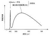
図4は、青色レーザ光源からの青色レーザ光及び青色レーザ光が蛍光体により波長変換された発光スペクトルを示すグラフである。レーザ光源LD2から発せられる青色レーザ光は、中心波長445nmの輝線で表され、青色レーザ光による蛍光体48Aからの励起発光光は、概ね450nm〜700nmの波長範囲で発光強度が増大する分光強度分布となる。この励起発光光と青色レーザ光との合波光によって、上述した疑似白色光が形成される。蛍光体48Bも同様である。 FIG. 4 is a graph showing an emission spectrum obtained by converting the wavelength of blue laser light and blue laser light from a blue laser light source with a phosphor. The blue laser light emitted from the laser light source LD2 is represented by a bright line having a central wavelength of 445 nm, and the excitation light emitted from the
ここで、本発明でいう白色光とは、厳密に可視光の全ての波長成分を含むものに限らず、例えば、上述した疑似白色光を始めとして、基準色であるR(赤),G(緑),B(青)等、特定の波長帯の光を含むものであればよい。つまり、本発明のいう白色光には、例えば、緑色から赤色にかけての波長成分を含む光や、青色から緑色にかけての波長成分を含む光等も広義に含まれるものとする。 Here, the white light referred to in the present invention is not limited to the one that strictly includes all the wavelength components of visible light. For example, the above-described pseudo white light and the reference colors R (red) and G ( Any material including light in a specific wavelength band such as green and B (blue) may be used. That is, the white light referred to in the present invention broadly includes, for example, light including a wavelength component from green to red, light including a wavelength component from blue to green, and the like.
前者(照明窓42A側)および後者(照明窓42B側)の照明光学系は同等の構成および作用のものであって、照明窓42A,42Bからは、基本的に同時に同等の照明光が照射される。 The former (
観察窓43の奥には、被検体の被観察領域の像光を取り込むための対物レンズユニット50等の光学系が取り付けられ、さらに対物レンズユニット50の奥には、被観察領域の画像情報を取得するCCD(Charge Coupled Device)イメージセンサやCMOS(Complementary Metal-Oxide Semiconductor)イメージセンサ等の撮像素子52が取り付けられている。 An optical system such as an
撮像素子52は、対物レンズユニット50からの光を受光面(撮像面)で受光し、受光した光を光電変換して撮像信号(アナログ信号)を出力する。本実施形態の撮像素子52はカラーCCDイメージセンサであり、その受光面には、図5に示す分光透過率を有するR色、G色、B色のカラーフィルタ54,56,58が設けられ、R画素、G画素、B画素の3色の画素を1組として、複数組の画素がマトリクス状に配列されている。 The imaging element 52 receives light from the
白色光は、その波長範囲が約470〜700nmであるため、R色、G色、B色のカラーフィルタ54,56,58は、白色光のうちそれぞれの分光透過率に応じた波長の光を透過し、R画素、G画素およびB画素の撮像信号が出力される。一方、半導体レーザLD1から発せられるレーザ光は、中心波長が473nmであるため、その反射光はB色のカラーフィルタ58のみを透過し、B画素の撮像信号のみが出力される。 Since white light has a wavelength range of about 470 to 700 nm, the R, G, and
光源装置12から発せられる4系統の光は、それぞれ対応する光ファイバ44A〜44Dによってスコープ先端部38まで導光され、導光される光、もしくは、導光される光が蛍光体48A,48Bに照射され、蛍光体48A,48Bから発せられる白色光が、スコープ先端部38の照明窓42A,42Bから被検体の被観察領域に向けて照射される。そして、照明光が照射された被観察領域の様子が対物レンズユニット50等により撮像素子52の受光面上に結像され、撮像素子52で光電変換されて撮像される。 The four systems of light emitted from the
撮像素子52からは、撮像された被検体の被観察領域の撮像信号(アナログ信号)が出力される。撮像素子52から出力される各画像の撮像信号(アナログ信号)は、スコープケーブル60を通じてA/D変換器62に入力される。A/D変換器62は、撮像素子52からの撮像信号(アナログ信号)をその電圧レベルに対応する画像信号(デジタル信号)に変換する。変換後の画像信号は、コネクタ部32Bを介してプロセッサ装置16の画像処理部66に入力される。 From the imaging element 52, an imaging signal (analog signal) of the observed region of the subject imaged is output. An image pickup signal (analog signal) of each image output from the image pickup device 52 is input to the A /
なお、図示はしていないが、操作部30及び内視鏡スコープ28の内部には、組織採取用処置具等を挿入する鉗子チャンネルや、送気・送水用のチャンネル等、各種のチャンネルが設けられている。 Although not shown in the drawing, various channels such as a forceps channel for inserting a tissue collection treatment tool, an air supply / water supply channel, and the like are provided in the
続いて、プロセッサ装置16は、制御部64と、画像処理部66と、記憶部68とを備えている。制御部64には、表示装置18および入力装置20が接続されている。 Subsequently, the
制御部64は、内視鏡装置14の切り替えスイッチ63や入力装置20から入力される観察モード等の指示に基づいて、画像処理部66、光源装置12の光源制御部22、および、表示装置18の動作を制御する。 The
画像処理部66は、制御部64の制御の基で、観察モードに基づき、内視鏡装置14から入力される画像信号に対して所定の画像処理を施す。画像処理部66は、白色光画像処理部72と、酸素飽和度画像処理部74とを備えている。 The
白色光画像処理部72は、白色光観察モードの場合に、内視鏡装置14から入力される画像信号に対して、白色光画像に適した所定の画像処理を施し、白色光画像信号を出力する。 In the white light observation mode, the white light
酸素飽和度画像処理部74は、酸素飽和度観察モードの場合に、内視鏡装置14から入力される画像信号に対して、第1および第2の照明窓から照射される照明光の配光分布の違いを補正し、被検体の血液量および血中ヘモグロビンの酸素飽和度の情報を算出し、算出した酸素飽和度の情報に基づいて、酸素飽和度の分布を疑似カラー表示するための酸素飽和度画像信号を出力する。酸素飽和度画像処理部74は、配光分布補正部75と、信号比算出部76と、相関関係記憶部78と、血液量−酸素飽和度算出部80と、酸素飽和度画像生成部82とを備えている。 In the oxygen saturation observation mode, the oxygen saturation
ここで、内視鏡装置14は、酸素飽和度観察モードの場合に、第1の照明光として473nmの光を第1の照明窓から照射して被検体を撮像して第1の画像の画像信号を取得する。また、第3の照明光として445nmの光を蛍光体48A,48Bに照射することによって、第2の照明光として蛍光体48A,48Bを透過した445nmの照明光および蛍光体48A,48Bから発せられる励起発光光を含む疑似白色光を第2の照明窓から照射して撮像して第2の画像の画像信号を取得する。さらに、第3の照明光を第1の照明窓からもしくは第1の照明光を第2の照明窓から照射して撮像して第3の画像の画像信号を取得する。 Here, in the oxygen saturation observation mode, the
配光分布補正部75は、第1および第2の画像の画像信号に現れる照明光の配光分布の違いを、第3の画像の画像信号を用いて補正する。 The light distribution
例えば、内視鏡装置14が、第3の照明光を第1の照明窓から照射して撮像して第3の画像を取得する場合、配光分布補正手段75は、第2および第3の画像の画像信号に基づいて補正係数を算出し、補正係数を用いて第1の画像の画像信号を補正する。また、内視鏡装置14が、第1の照明光を第2の照明窓から照射して撮像して第3の画像を取得する場合、配光分布補正手段75は、第1および第3の画像の画像信号に基づいて補正係数を算出し、補正係数を用いて第2の画像の画像信号を補正する。 For example, when the
信号比算出部76は、血管部分の画像信号とそれ以外の部分の画像信号との差に基づいて、配光分布の違いが補正された画像信号から血管領域を特定する。そして、信号比算出部76は、血管領域内の同じ位置の画素について、血中ヘモグロビンの酸素飽和度に応じて還元ヘモグロビンと酸化ヘモグロビンの吸光係数(吸光度)の大小関係が逆転する波長範囲の2つの狭帯域光の反射光に対応する画像信号をS1,S2とし、吸光係数が同じになる波長範囲の1つの狭帯域光の反射光に対応する画像信号をS3として、信号比S1/S3およびS2/S3を求める。 Based on the difference between the image signal of the blood vessel portion and the image signal of the other portion, the signal
相関関係記憶部78は、信号比S1/S3およびS2/S3と、血液量および酸素飽和度との相関関係を記憶している。この相関関係は、血管が図6に示すヘモグロビンの吸光係数を有する場合の相関関係であり、これまでの診断等で蓄積された多数の画像信号を分析することにより得られたものである。 The
図6に示すように、血中ヘモグロビンは、照射する光の波長によって吸光係数μaが変化する吸光特性を持っている。吸光係数μaは、ヘモグロビンの光の吸収の大きさである吸光度を表す。また、酸素と結合していない還元ヘモグロビン70と、酸素と結合した酸化ヘモグロビン71は、異なる吸光特性を持っており、同じ吸光度(吸光係数μa)を示す等吸収点(図6における各ヘモグロビン70,71の交点)を除いて、吸光度に差が生じる。 As shown in FIG. 6, blood hemoglobin has a light absorption characteristic in which the light absorption coefficient μa changes depending on the wavelength of light to be irradiated. The extinction coefficient μa represents absorbance, which is the magnitude of light absorption of hemoglobin. Further, the reduced hemoglobin 70 not bound to oxygen and the oxygenated hemoglobin 71 bound to oxygen have different light absorption characteristics and have the same absorption point (absorption coefficient μa) (each hemoglobin 70, FIG. Except for 71 intersection points), there is a difference in absorbance.
一般的に、図6の分布は撮像対象の部位によって非線形に変化するため、実際の生体組織の計測や光伝播シミュレーション等により予め求めておく必要がある。 In general, since the distribution of FIG. 6 changes nonlinearly depending on the region to be imaged, it is necessary to obtain in advance by actual measurement of biological tissue, light propagation simulation, or the like.
図7は、信号比B/GおよびR/Gと、血液量および酸素飽和度との相関関係を表すグラフである。このグラフの横軸はlog(R/G)、縦軸はlog(B/G)であり、信号比R/Gは信号比S1/S3に対応し、信号比B/Gは信号比S2/S3に対応するものとする。このグラフに示すように、信号比R/Gの値は、血液量に依存して変化し、血液量が大きくなるほど大きくなる。また、信号比B/Gの値は、血液量および酸素飽和度の両方に依存して変化する。つまり、信号比B/Gの値は、血液量が大きくなるほど大きくなるとともに、酸素飽和度が低くなるほど大きくなる。 FIG. 7 is a graph showing the correlation between the signal ratios B / G and R / G, blood volume, and oxygen saturation. The horizontal axis of this graph is log (R / G), the vertical axis is log (B / G), the signal ratio R / G corresponds to the signal ratio S1 / S3, and the signal ratio B / G is the signal ratio S2 / S. It shall correspond to S3. As shown in this graph, the value of the signal ratio R / G varies depending on the blood volume, and increases as the blood volume increases. The value of the signal ratio B / G varies depending on both the blood volume and the oxygen saturation. That is, the value of the signal ratio B / G increases as the blood volume increases and increases as the oxygen saturation level decreases.
血液量−酸素飽和度算出部80は、相関関係記憶部78に記憶された相関関係に基づき、信号比算出部76で算出された信号比S1/S3およびS2/S3に対応する血液量および酸素飽和度を算出する。 The blood volume-oxygen
酸素飽和度画像生成部82は、酸素飽和度の大小に応じてカラー情報が割り当てられたカラーテーブルを備えている。カラーテーブルは、入力装置20から入力される指示によって切り替えが可能であり、例えば、胃、十二指腸、小腸等のように、観察する部位に合ったものが選択される。酸素飽和度画像生成部82は、カラーテーブルを用い、血液量−酸素飽和度算出部80で算出された酸素飽和度に対応するカラー情報を特定する。そして、酸素飽和度画像生成部82は、血管領域内の全ての画素についてのカラー情報を特定すると、例えば、白色光画像の画像信号に対してカラー情報を反映させることにより、血中ヘモグロビンの酸素飽和度が反映(疑似カラー表示)された酸素飽和度画像信号を生成する。 The oxygen saturation image generation unit 82 includes a color table to which color information is assigned according to the magnitude of oxygen saturation. The color table can be switched by an instruction input from the
画像処理部66で処理された画像信号は、制御部64に送られ、制御部64で各種情報と共に内視鏡観察画像にされて表示装置18に表示され、必要に応じて、メモリやストレージ装置からなる記憶部68に記憶される。 The image signal processed by the
以下、血液量および酸素飽和度の算出方法について説明する。 Hereinafter, a method for calculating blood volume and oxygen saturation will be described.
被検体の粘膜組織内に光が入射すると、その一部は血管のところで吸収され、吸収されなかった光のさらに一部が反射光として戻ってくる。この時、血管の深さが深くなるほど、その上の組織からの散乱の影響を大きく受けることになる。 When light enters the mucosal tissue of the subject, a part of the light is absorbed in the blood vessel, and a part of the light that has not been absorbed returns as reflected light. At this time, the greater the depth of the blood vessel, the greater the influence of scattering from the tissue above it.
ところで、470〜700nmの波長範囲の光は、粘膜組織内での散乱係数が小さく、かつ波長依存性が小さいという性質がある。このため、この波長範囲の光を照明光として用いることによって、血管の深さの影響を低減しつつ、血液量および酸素飽和度の情報を含む血液情報を得ることができる。従って、内視鏡診断装置10では、血中ヘモグロビンの酸素飽和度に応じて吸光係数が変化する2つ以上の波長範囲の反射光および変化しない1つ以上の波長範囲の反射光を含む、460〜700nmの波長範囲の異なる3つ以上の反射光に対応する画像信号を用いて、血中ヘモグロビンの酸素飽和度を算出する。 By the way, light in the wavelength range of 470 to 700 nm has a property that the scattering coefficient in the mucosal tissue is small and the wavelength dependency is small. Therefore, by using light in this wavelength range as illumination light, blood information including information on blood volume and oxygen saturation can be obtained while reducing the influence of blood vessel depth. Therefore, the endoscope
ここで、血中ヘモグロビンの吸光係数の波長依存性から、以下の3つのことが言える。
・波長470nm近辺(例えば、中心波長470nm±10nmのBの波長範囲)では酸素飽和度の変化に応じて吸光係数が大きく変化する。
・540〜580nmのGの波長範囲で平均すると、酸素飽和度の影響を受けにくい。
・590〜700nmのRの波長範囲では、酸素飽和度によって一見吸光係数が大きく変化するように見えるが、吸光係数の値自体が非常に小さいので、結果的に酸素飽和度の影響を受けにくい。Here, the following three things can be said from the wavelength dependence of the extinction coefficient of blood hemoglobin.
In the vicinity of the wavelength of 470 nm (for example, the B wavelength range of the central wavelength of 470 nm ± 10 nm), the extinction coefficient changes greatly according to the change in the oxygen saturation.
-When averaged over the G wavelength range of 540 to 580 nm, it is less susceptible to oxygen saturation.
In the R wavelength range of 590 to 700 nm, the extinction coefficient seems to change greatly depending on the oxygen saturation, but the value of the extinction coefficient itself is very small so that it is hardly affected by the oxygen saturation.
また、粘膜の反射スペクトルから以下の2つの性質がある。
・Rの波長範囲ではヘモグロビンの影響がほとんどないと見なせるが、Gの波長範囲では吸収が生じるので、血液量(血管の太さあるいは血管の密度に対応)が大きいほど、Gの波長範囲での反射率とRの波長範囲での反射率との差が大きくなる。
・波長470nm近辺の反射率とGの波長範囲での反射率との差は、酸素飽和度が低いほど大きくなり、同時に、血液量が大きいほど大きくなる。Moreover, there are the following two properties from the reflection spectrum of the mucous membrane.
・ In the wavelength range of R, it can be considered that there is almost no influence of hemoglobin. However, since absorption occurs in the wavelength range of G, the larger the blood volume (corresponding to the thickness of the blood vessel or the density of the blood vessel), The difference between the reflectance and the reflectance in the R wavelength range is increased.
The difference between the reflectance near the wavelength of 470 nm and the reflectance in the G wavelength range increases as the oxygen saturation level decreases, and at the same time increases as the blood volume increases.
つまり、B画素の画像信号BとG画素の画像信号Gとの間の信号比B/Gは、その値が酸素飽和度および血液量の両方に依存して変化し、G画素の画像信号GとR画素の画像信号Rとの間の信号比R/Gは、その値が主に血液量だけに依存して変化する。従って、この性質を利用することによって、波長470nm近辺、GおよびRの波長範囲を含む3波長範囲の分光画像から、酸素飽和度と血液量とを分離してそれぞれの値を正確に算出することができる。これに基づいて作成したものが、信号比B/GおよびR/Gと、血液量および酸素飽和度との相関関係を表す前述の図7のグラフである。 That is, the signal ratio B / G between the image signal B of the B pixel and the image signal G of the G pixel changes depending on both the oxygen saturation and the blood volume, and the image signal G of the G pixel And the signal ratio R / G between the R pixel and the image signal R of the R pixel varies depending on the value mainly depending on only the blood volume. Therefore, by utilizing this property, oxygen saturation and blood volume can be separated from a spectral image of a three-wavelength range including the wavelength range of G and R in the vicinity of a wavelength of 470 nm, and each value can be accurately calculated. Can do. Based on this, the graph of FIG. 7 described above showing the correlation between the signal ratios B / G and R / G, the blood volume, and the oxygen saturation is shown.
次に、配光分布の違いの補正方法について説明する。 Next, a method for correcting the difference in light distribution will be described.
酸素飽和度は、例えば、前述の第1および第2の画像の画像信号を用いて算出することができる。しかし、第1および第2の画像の撮像時には、照明光が照射される照明窓が異なる(第1の画像の撮像時は第1の照明窓、第2の画像の撮像時は第2の照明窓)ため、被検体上の配光分布が異なる。配光分布の違いを補正せずに酸素飽和度を算出すると、不適切な値が算出される虞があるため、前述のように、第3の画像の画像信号を利用して、第1および第2の画像の画像信号に現れる配光分布の違いを補正する。 The oxygen saturation can be calculated using, for example, the image signals of the first and second images described above. However, when the first and second images are captured, the illumination windows irradiated with the illumination light are different (the first illumination window when capturing the first image, and the second illumination when capturing the second image). Therefore, the light distribution on the subject is different. If the oxygen saturation is calculated without correcting the difference in the light distribution, an inappropriate value may be calculated. As described above, the first and the first images are obtained using the image signal of the third image. The difference in the light distribution that appears in the image signal of the second image is corrected.
ここで、酸素飽和度観察モードの場合に、内視鏡装置14によって撮像される第1の画像の画像信号をB1,G1,R1、第2の画像の画像信号をB2,G2,R2、第3の画像の画像信号をB3,G3,R3とする。 Here, in the oxygen saturation observation mode, the image signals of the first image captured by the
撮像素子52の分光感度と蛍光体48A,48Bから発せられる白色光のスペクトルとから、画像信号B2は、中心波長445nmの励起光と、蛍光体48A,48Bから発せられる少量の励起発光光の画像信号とだけを含む信号となる。そのため、画像信号B2は、おおよそ中心波長445nm単色の照明光による画像の画像信号に近いと見なすことができる。 From the spectral sensitivity of the image sensor 52 and the spectrum of white light emitted from the
従って、内視鏡装置14が、第3の照明光を第1の照明窓から照射して撮像して第3の画像を取得する場合、配光分布補正部75は、画像信号B2と画像信号B3との信号比C=B2/B3を算出して補正係数とし、この補正係数Cを第1の画像の画像信号B1,G1,R1に掛けることによって、第1の照明窓から照射される照明光の配光分布を、第2の照明窓から照射される照明光の配光分布に合わせるように補正することができる。 Therefore, when the
一方、内視鏡装置14が、第1の照明光を第2の照明窓から照射して撮像して第3の画像を取得する場合、配光分布補正部75は、画像信号B1と画像信号B3との信号比C=B1/B3を算出して補正係数とし、この補正係数Cを画像信号B2,G2,R2に掛けることによって、第2の照明窓から照射される照明光の配光分布を、第1の照明窓から照射される照明光の配光分布に合わせるように補正することができる。 On the other hand, when the
ここで、配光分布の違いを表す補正係数Cは、本来空間的に細かい構造を持っていない。そのため、低周波成分抽出手段を用いて、補正係数Cを算出するために用いる画像信号B2およびB3から、画像を縮小する、あるいは、平均値フィルタを掛けるなどして低周波成分の信号のみを抽出し、データ量を削減しておくことが望ましい。 Here, the correction coefficient C representing the difference in the light distribution does not have a spatially fine structure. Therefore, only low-frequency component signals are extracted from the image signals B2 and B3 used to calculate the correction coefficient C by using a low-frequency component extracting means by reducing the image or applying an average value filter. It is desirable to reduce the amount of data.
また、第1および第2の画像の撮像時には、照明光が照射される照明窓の位置が異なるため、光源の正反射によって、画像上に現れる白色の輝点の位置が異なる。そのため、補正係数Cを算出するためには、この白色の輝点の影響を受けないように、輝点領域除去手段を用いて、画像信号B2およびB3から輝点領域を除去した後に低周波成分を抽出することが望ましい。白色の輝点を除去する方法としては、例えば、画像信号に閾値を設けて、ある閾値以上の画像信号を持つ領域を、周辺の画像信号値に置換する方法を例示することができる。 In addition, when the first and second images are captured, the position of the illumination window irradiated with the illumination light is different, so the position of the white bright spot appearing on the image is different due to regular reflection of the light source. Therefore, in order to calculate the correction coefficient C, the low-frequency component is used after removing the bright spot area from the image signals B2 and B3 by using the bright spot area removing means so as not to be affected by the white bright spot. It is desirable to extract As a method for removing white bright spots, for example, a method of setting a threshold value for an image signal and replacing a region having an image signal equal to or higher than a certain threshold value with a peripheral image signal value can be exemplified.
次に、内視鏡診断装置10の動作を説明する。
まず、白色光観察モードの場合の動作を説明する。Next, the operation of the
First, the operation in the white light observation mode will be described.
観察モード等の指示が、内視鏡装置14の切り替えスイッチ63や入力装置20からプロセッサ装置16の制御部64に入力され、白色光観察モードに設定される。 An instruction such as an observation mode is input from the
白色光観察モードの場合、プロセッサ装置16の制御部64により光源装置12の光源制御部22の動作が制御され、レーザ光源LD1がオフ、レーザ光源LD2がオンとされ、レーザ光源LD2から2系統の白色光観察用の励起光が発せられる。 In the white light observation mode, the operation of the light
内視鏡装置14では、光源装置12から発せられる2系統の白色光観察用の励起光が、それぞれ、光ファイバ44B,44Dによってスコープ先端部38の蛍光体48A,48Bへ導光される。これにより、蛍光体48A,48Bから白色光が発せられ、それぞれ、レンズ46B,46Dを介して照明窓42A,42Bから被検体の被観察領域に照射される。そして、被観察領域からの反射光が対物レンズユニット50により集光され、撮像素子52により光電変換されて白色光画像の撮像信号(アナログ信号)が出力される。 In the
白色光画像の撮像信号(アナログ信号)は、A/D変換器62により画像信号(デジタル信号)に変換され、観察モードに従って、画像処理部68の白色光画像処理部72により白色光画像に適した所定の画像処理が施され、白色光画像信号が出力される。そして、制御部64により、白色光画像信号から白色光画像が発生され、白色光画像が表示装置18上に表示される。 The imaging signal (analog signal) of the white light image is converted into an image signal (digital signal) by the A /
次に、酸素飽和度観察モードの場合の動作を説明する。 Next, the operation in the oxygen saturation observation mode will be described.
まず、観察モードが、通常光画像モードから酸素飽和度観察モードに切り替えられる。酸素飽和度観察モードになると、このモード切替時点での白色光画像信号が、酸素飽和度画像の生成に用いられる基準画像として記憶部68に記憶される。また、入力装置20の操作によって、胃、十二指腸、小腸など現時点での観察部位の情報が指定される。これにより、酸素飽和度画像生成部82において、その観察部位に応じたカラーテーブルが選択される。 First, the observation mode is switched from the normal light image mode to the oxygen saturation observation mode. In the oxygen saturation observation mode, the white light image signal at the time of switching the mode is stored in the
酸素飽和度観察モードでは、3フレームを1組として、1フレーム毎に照射パターンの異なる照明光が照射される。まず、第1フレームにおいてLD1がオン、LD2がオフとされ、光源装置12から2系統の酸素飽和度観察用のレーザ光が発せられる。 In the oxygen saturation observation mode, illumination light having a different irradiation pattern is irradiated for each frame with one set of three frames. First, in the first frame, LD1 is turned on and LD2 is turned off, and two light sources of oxygen saturation observation laser light are emitted from the
内視鏡装置14では、光源装置12から発せられる2系統の酸素飽和度観察用のレーザ光が、それぞれ、光ファイバ44A,44Cによってスコープ先端部38まで導光され、レンズ46A,46Cを介して第1の照明窓から被検体の被観察領域に照射される。そして、被観察領域からの反射光が対物レンズユニット50により集光され、撮像素子52により光電変換されて酸素飽和度観察用の狭帯域光画像(第1の画像)の撮像信号(アナログ信号)が出力される。狭帯域光画像の撮像信号(アナログ信号)は、A/D変換器62により画像信号(デジタル信号)に変換された後、一旦、制御部64の制御により記憶部68に記憶される。 In the
続いて、第2フレームにおいてLD1がオフ、LD2がオンとされ、光源装置12から2系統の白色光観察用の励起光が発せられる。そして、内視鏡装置14において、励起光が蛍光体48A,48Bに照射されて白色光が発せられ、蛍光体48A,48Bから発せられる白色光が第2の照明窓から照射される。この時の内視鏡装置14の動作は、白色光観察モードの場合と同じであり、白色光画像(第2の画像)の画像信号である白色光画像信号が記憶部68に記憶される。 Subsequently, in the second frame, LD1 is turned off and LD2 is turned on, and two types of excitation light for white light observation are emitted from the
第3フレームでは、第2フレームにおけるLD1がオフ、LD2がオンの状態が継続され、光源装置12から2系統の配光分布補正用のレーザ光が発せられ、第1の照明窓から照射される。この時の内視鏡装置14の動作は第1フレームの場合と同様であり、配光分布補正用の狭帯域光画像(第3の画像)の画像信号が記憶部68に記憶される。 In the third frame, LD1 in the second frame is kept off and LD2 is kept on, and two light distribution distribution correction laser lights are emitted from the
ここで、第1フレームで得られる第1の画像の画像信号をB1,G1,R1、第2フレームで得られる第2の画像の画像信号をB2,G2,R2、第3フレームで得られる第3の画像の画像信号をB3,G3,R3とする。B1は、中心波長473nmの単色照明の画像信号、G2は、蛍光体48A,48Bから発せられる励起発光光の主として540〜580nmの波長範囲の分光照明の画像信号、R2は、同590〜700nmの波長範囲の分光照明の画像信号である。また、B1およびR2は、血中ヘモグロビンの酸素飽和度に応じて吸光係数が変化する2つの波長範囲の反射光に対応する画像信号であり、G2は、吸光係数が変化しない1つの波長範囲の反射光に対応する画像信号である。 Here, the image signals of the first image obtained in the first frame are B1, G1, R1, and the image signals of the second image obtained in the second frame are obtained in B2, G2, R2, and the third frame. The image signals of the third image are B3, G3, and R3. B1 is an image signal of monochromatic illumination having a central wavelength of 473 nm, G2 is an image signal of spectral illumination mainly in the wavelength range of 540 to 580 nm of excitation light emitted from the
配光分布補正部75は、第1〜第3の画像の画像信号が記憶部68に記憶された後、記憶部68に記憶されている第1〜第3の画像の画像信号を読み出す。そして、画像信号B2と画像信号B3との信号比C=B2/B3を算出して補正係数とし、この補正係数Cを画像信号B1,G1,R1に掛けることによって、第1の照明窓から照射される照明光の配光分布を、第2の照明窓から照射される照明光の配光分布に合わせるように補正する。補正後の第1の画像の画像信号は再度記憶部68に記憶される。 The light distribution
続いて、信号比算出部76は、まず、記憶部68に記憶されている第1の画像(酸素飽和度観察用の狭帯域光画像)および第2の画像(白色光画像)から、血管を含む血管領域を特定する。続いて、信号比算出部76は、血管領域内の同じ位置の画素について、画像信号B1と画像信号G2との間の信号比B1/G2と、画像信号G2と画像信号R2との間の信号比R2/G2を算出する。 Subsequently, the signal
前述のように、信号比B1/G2は、その値が酸素飽和度および血液量の両方に依存して変化し、信号比R2/G2は、その値が主に血液量だけに依存して変化する。血液量−酸素飽和度算出部80は、図7に示す、相関関係記憶部78に記憶されている、これらの信号比B1/G2およびR2/G2と、血液量および酸素飽和度との間の相関関係に基づいて、信号比B1/G2およびR2/G2に対応する、血液量および酸素飽和度の情報を算出する。 As described above, the signal ratio B1 / G2 varies depending on both the oxygen saturation and the blood volume, and the signal ratio R2 / G2 varies depending on only the blood volume. To do. The blood volume-oxygen
酸素飽和度画像生成部82は、血液量および酸素飽和度が求まると、選択されたカラーテーブルに基づき、酸素飽和度に対応するカラー情報を特定する。そして、血管領域内の全ての画素について、上述した手順で、血液量および酸素飽和度を求め、酸素飽和度に対応するカラー情報を特定する。そして、血管領域内の全ての画素について酸素飽和度とそれに対応するカラー情報が得られると、酸素飽和度画像生成部82は、記憶部68から基準画像となる白色光画像信号を読み出し、この白色光画像に対してカラー情報を反映させることにより、酸素飽和度画像信号を生成する。生成された酸素飽和度画像信号は、記憶部68に記憶される。 When the blood volume and the oxygen saturation are obtained, the oxygen saturation image generation unit 82 specifies color information corresponding to the oxygen saturation based on the selected color table. Then, the blood volume and the oxygen saturation are obtained for all the pixels in the blood vessel region by the above-described procedure, and the color information corresponding to the oxygen saturation is specified. When oxygen saturation and corresponding color information are obtained for all the pixels in the blood vessel region, the oxygen saturation image generation unit 82 reads the white light image signal serving as the reference image from the
そして、制御部64は、記憶部68から酸素飽和度画像信号を読み出し、読み出した酸素飽和度画像信号に基づいて、酸素飽和度画像を表示装置18に疑似カラー表示する。 Then, the
上記のようにして、内視鏡診断装置10では、第1および第2の照明窓から照射される照明光の配光分布の違いを補正することにより、正確な酸素飽和度画像を得ることができるため、医師による診断精度を向上させることができる。また、内視鏡診断装置10では、血管の深さの影響を低減しつつ、血液量を考慮して酸素飽和度の情報を正確に算出し、酸素飽和度の分布を疑似カラー画像として表示することができる。 As described above, the endoscope
次に、第2の実施形態について説明する。 Next, a second embodiment will be described.
図8は、本発明に係る内視鏡診断装置の構成を表す第2の実施形態の外観図、図9は、その内部構成を表すブロック図である。以下、第2の実施形態の内視鏡診断装置11について、第1の実施形態の内視鏡診断装置10と異なる部分を中心に説明する。 FIG. 8 is an external view of the second embodiment showing the configuration of the endoscope diagnosis apparatus according to the present invention, and FIG. 9 is a block diagram showing the internal configuration thereof. Hereinafter, the endoscope
本実施形態の内視鏡診断装置11は、白色光観察モードと、被検体に白色光と自家蛍光観察用の励起光とを交互に照射して白色光画像と自家蛍光画像とを交互に撮像し、両者の合成画像を生成(して観察)する自家蛍光観察モードとを有する。 The
光源装置12のレーザ光源LD1からは、中心波長が405nmである、所定の波長範囲(例えば、中心波長±10nm)の狭帯域光が発せられる。レーザ光源LD1は、自家蛍光観察用の励起光を発する光源である。 The laser light source LD1 of the
内視鏡装置14の内視鏡スコープ28の先端部には、撮像素子52の受光面で受光される光のうち、光源装置12から照射される励起光を含む所定の波長範囲の光をカット(遮光)する励起光カットフィルタ59がキャップとして装着されている。 At the distal end portion of the
図10は、励起光カットフィルタの分光透過率特性を表すグラフである。グラフの縦軸は光強度、横軸は光の波長である。このグラフに示すように、所定の光強度の中心波長405nmの励起光を被検体に照射すると、励起光が照射された被検体の部位から、約420〜650nmの波長帯域の自家蛍光が発せられる。自家蛍光は、励起光と比べて極めて微弱な光であるため、自家蛍光を観察するためには、励起光カットフィルタ59によって励起光をカットする必要がある。 FIG. 10 is a graph showing the spectral transmittance characteristics of the excitation light cut filter. The vertical axis of the graph is the light intensity, and the horizontal axis is the wavelength of the light. As shown in this graph, when the subject is irradiated with excitation light having a center wavelength of 405 nm with a predetermined light intensity, autofluorescence in a wavelength band of about 420 to 650 nm is emitted from the portion of the subject irradiated with the excitation light. . Since the autofluorescence is extremely weak light compared to the excitation light, it is necessary to cut the excitation light by the excitation light cut
このグラフに示す励起光カットフィルタ59は、励起光の405nm±10nmの波長範囲を含む415nm以下の波長範囲の光をカットする。つまり、励起光カットフィルタ59を透過する光のうち、415nm以下の波長範囲の光は遮光され、撮像素子52の受光面には受光されない。なお、励起光の波長範囲の光のみをカットすればよく、これ以外の波長範囲の光はカットしない方が望ましい。 The excitation light cut
プロセッサ装置16の画像処理部66は、白色光画像処理部72と、自家蛍光画像処理部84とを備えている。 The
自家蛍光画像処理部84は、自家蛍光観察モードの場合に、内視鏡装置14から入力される画像信号に対して、第1および第2の照明窓から照射される照明光の配光分布の違いを補正し、白色光画像と自家蛍光画像との合成画像の画像信号(自家蛍光画像信号)を出力する。自家蛍光画像処理部84は、配光分布補正部75と、自家蛍光信号算出部86と、自家蛍光画像生成部88とを備えている。 The autofluorescence
ここで、内視鏡装置14は、自家蛍光観察モードの場合に、第1の照明光として405nmの光を照射して被検体を撮像して第1の画像の画像信号を取得する。また、第3の照明光として445nmの光を蛍光体48A,48Bに照射することによって、第2の照明光として蛍光体48A,48Bから発せられる疑似白色光を照射して撮像して第2の画像の画像信号を取得する。さらに、第3の照明光を第1の照明窓からもしくは第1の照明光を第2の照明窓から照射して撮像して第3の画像の画像信号を取得する。 Here, in the case of the autofluorescence observation mode, the
第1の実施形態の場合と同様に、第1および第2の画像の撮像時には、照明光が照射される照明窓が異なる(第1の画像の撮像時は第1の照明窓、第2の画像の撮像時は第2の照明窓)ため、被検体上の配光分布が異なる。配光分布の違いを補正せずに自家蛍光画像信号を算出すると、不適切な値が算出される虞があるため、配光分布補正部75は、第1の実施形態の場合と同様にして、第3の画像の画像信号を利用して、第1および第2の画像の画像信号に現れる配光分布の違いを補正する。 As in the case of the first embodiment, when the first and second images are captured, the illumination windows irradiated with the illumination light are different (when the first image is captured, the first illumination window and the second illumination window are different). Since the second illumination window is used when an image is captured, the light distribution on the subject is different. If the autofluorescence image signal is calculated without correcting the difference in the light distribution, an inappropriate value may be calculated. Therefore, the light distribution
自家蛍光画像は、白色光画像と比べて輝度成分が非常に微弱であるため、両者の合成画像において自家蛍光画像を適切に観察するためには、両者の特性(γ値、輝度レベル、コントラスト等)のバランスを適切に設定する必要がある。自家蛍光信号算出部86は、配光分布の違いが補正された画像信号に基づいて、自家蛍光観察用の狭帯域光画像(第1の画像)の画像信号と、参照画像としての白色光画像(第2の画像)の画像信号とのバランスを調整するために、自家蛍光観察用の狭帯域光画像の画像信号を補正することによって自家蛍光信号を算出する。 Since the autofluorescence image has a very weak luminance component compared to the white light image, in order to properly observe the autofluorescence image in the composite image of both, the characteristics of both (gamma value, luminance level, contrast, etc.) ) Must be set appropriately. The autofluorescence
自家蛍光画像生成部88は、白色光画像信号と蛍光画像信号とを画素毎に合成することにより、参照画像となる白色光画像において自家蛍光の分布が反映されるように疑似カラーで表現された合成画像の画像信号(自家蛍光画像信号)を生成する。 The self-fluorescent
次に、自家蛍光観察モードの場合の動作を説明する。 Next, the operation in the auto fluorescence observation mode will be described.
自家蛍光観察モードでは、3フレームを1組として、1フレーム毎に照射パターンの異なる照明光が照射される。内視鏡装置14において、第1〜第3フレームで第1〜第3の画像の画像信号が記憶部68に記憶され、プロセッサ装置16において、配光分布の違いが補正されるまでの動作は、レーザ光源LD1から照射される酸素飽和度観察用のレーザ光が自家蛍光観察用のレーザ光になる点を除いて、第1の実施形態の場合と同様である。 In the auto-fluorescence observation mode, illumination light having a different irradiation pattern is irradiated for each frame with one set of three frames. In the
自家蛍光信号算出部86は、第1〜第3の画像の画像信号が記憶部68に記憶された後、記憶部68に記憶されている第1〜第3の画像の画像信号を読み出す。そして、例えば、自家蛍光観察用の狭帯域光画像(第1の画像)のG画素の画像信号G1と、参照画像としての白色光画像(第2の画像)のG画素の画像信号G2との信号比G1/G2に基づいて、両者のバランスを調整するために、自家蛍光観察用の狭帯域光画像の画像信号を補正することによって自家蛍光信号を算出する。 The autofluorescence
自家蛍光画像生成部88は、例えば、白色光画像のR画像およびB画像をそれぞれRチャンネル信号およびBチャンネル信号として割り当て、自家蛍光画像のG画像をGチャンネル信号として割り当てて、RGBの各チャンネル信号を合成することによって、自家蛍光の分布が疑似カラーで表現される合成画像の画像信号(自家蛍光画像信号)を生成する。合成画像は、例えば、正常部がG色の色調で表示され、病変部がマゼンタの色調で表示されるように合成処理される。 The autofluorescence
そして、制御部64は、記憶部68から自家蛍光画像信号を読み出し、読み出した自家蛍光画像信号に基づいて、参照画像となる白色光画像と自家蛍光画像との合成画像を表示装置18に表示する。 Then, the
第2の実施形態の内視鏡診断装置11においても、第1および第2の照明窓から照射される照明光の配光分布の違いを補正することにより、正確な自家蛍光画像を得ることができるため、医師による診断精度を向上させることができる。 Also in the
なお、内視鏡装置は、血中ヘモグロビンの酸素飽和度に応じて吸光係数が変化する2つの波長範囲の反射光および吸光係数が変化しない1つの波長範囲の反射光を含む、460〜700nmの波長範囲の異なる3つ以上の反射光に対応する画像信号を取得することができればよく、光源の種類(レーザ光源、白色光光源、レーザ光源および蛍光体の組合せ、など)および波長、撮像素子の種別(カラーもしくはモノクロ)、照明光の照射パターン(1フレーム毎、複数フレームを1組とする、など)、照明光学系の形態(1灯、2灯、4灯、など)等の組合せは、必要に応じて適宜変更することができる。 Note that the endoscope apparatus includes reflected light in two wavelength ranges in which the absorption coefficient changes according to the oxygen saturation of blood hemoglobin and reflected light in one wavelength range in which the absorption coefficient does not change. It suffices if image signals corresponding to three or more reflected lights having different wavelength ranges can be acquired, and the type of light source (laser light source, white light source, combination of laser light source and phosphor, etc.), wavelength, imaging device Combinations of type (color or monochrome), illumination light irradiation pattern (one frame, one set of multiple frames, etc.), illumination optical system form (one light, two lights, four lights, etc.) It can be changed as necessary.
本発明は、基本的に以上のようなものである。
以上、本発明について詳細に説明したが、本発明は上記実施形態に限定されず、本発明の主旨を逸脱しない範囲において、種々の改良や変更をしてもよいのはもちろんである。The present invention is basically as described above.
Although the present invention has been described in detail above, the present invention is not limited to the above-described embodiment, and it is needless to say that various improvements and modifications may be made without departing from the gist of the present invention.
10,11 内視鏡診断装置
12 光源装置
14 内視鏡装置
16 プロセッサ装置
18 表示装置
20 入力装置
22 光源制御部
LD1,LD2 レーザ光源
24 コンバイナ
26 カプラ
28 内視鏡スコープ
30 操作部
32A,32B コネクタ部
34 軟性部
36 湾曲部
38 スコープ先端部
40 アングルノブ
42A,42B 照明窓
43 観察窓
44A〜44D 光ファイバ
46A〜46D レンズ
48A,48B 蛍光体
50 対物レンズユニット
52 撮像素子
54,56,58 カラーフィルタ
59 励起光カットフィルタ
60 スコープケーブル
62 A/D変換器
63 切り替えスイッチ
64 制御部
66 画像処理部
68 記憶部
70 還元ヘモグロビン
71 酸化ヘモグロビン
72 白色光画像処理部
74 酸素飽和度画像処理部
75 配光分布補正部
76 信号比算出部
78 相関関係記憶部
80 血液量−酸素飽和度算出部
82 酸素飽和度画像生成部
84 自家蛍光画像処理部
86 自家蛍光信号算出部
88 自家蛍光画像生成部DESCRIPTION OF
Claims (8)
Translated fromJapanese内視鏡スコープの先端部の異なる位置に配置された第1および第2の照明窓を有し、第1の照明光を前記第1の照明窓から照射して撮像した第1の画像の画像信号、第3の照明光を前記内視鏡スコープの先端部に配置された蛍光体に照射することによって、該蛍光体を透過した第3の照明光および該蛍光体から発せられる励起発光光を含む疑似白色光である第2の照明光を前記第2の照明窓から照射して撮像した第2の画像の画像信号、および、前記第3の照明光を前記第1の照明窓からもしくは前記第1の照明光を前記第2の照明窓から照射して撮像した第3の画像の画像信号を取得する内視鏡装置と、
前記第1および第2の画像の画像信号に現れる前記第1および第2の照明光の配光分布の違いを、前記第3の画像の画像信号を用いて補正する配光分布補正手段とを備えることを特徴とする内視鏡診断装置。An endoscope diagnostic apparatus that irradiates a subject with illumination light and captures an image of the subject,
An image of a first image having first and second illumination windows arranged at different positions on the distal end portion of the endoscope scope and imaged by irradiating the first illumination light from the first illumination window By irradiating the phosphor disposed at the distal end portion of the endoscope scope with the signal and the third illumination light, the third illumination light transmitted through the phosphor and the excitation light emitted from the phosphor are generated. An image signal of a second image captured by irradiating the second illumination light, which is pseudo white light including, from the second illumination window, and the third illumination light from the first illumination window or the An endoscope apparatus for acquiring an image signal of a third image captured by irradiating the first illumination light from the second illumination window;
Light distribution distribution correction means for correcting a difference in light distribution between the first and second illumination lights appearing in the image signals of the first and second images using the image signal of the third image; An endoscopic diagnosis apparatus comprising:
前記配光分布補正手段は、前記第2および第3の画像の画像信号に基づいて補正係数を算出し、該補正係数を用いて前記第1の画像の画像信号を補正するものである請求項1に記載の内視鏡診断装置。The endoscopic device acquires an image signal of a third image captured by irradiating the third illumination light from the first illumination window,
The light distribution distribution correcting unit calculates a correction coefficient based on the image signals of the second and third images, and corrects the image signal of the first image using the correction coefficient. The endoscope diagnosis apparatus according to 1.
前記配光分布補正手段は、前記第1および第3の画像の画像信号に基づいて補正係数を算出し、該補正係数を用いて前記第2の画像の画像信号を補正するものである請求項1に記載の内視鏡診断装置。The endoscope apparatus acquires an image signal of a third image captured by irradiating the first illumination light from the second illumination window,
The light distribution distribution correcting unit calculates a correction coefficient based on the image signals of the first and third images, and corrects the image signal of the second image using the correction coefficient. The endoscope diagnosis apparatus according to 1.
前記配光分布補正手段は、前記輝点領域除去手段によって前記白色の輝点領域の信号が除去された第1〜第3の画像の画像信号に基づいて、前記第1および第2の照明光の配光分布の違いを補正するものである請求項1〜3のいずれかに記載の内視鏡診断装置。Furthermore, it comprises a bright spot area removing means for removing the signal of the white bright spot area appearing on the first to third images by regular reflection of illumination light from the image signals of the first to third images,
The light distribution distribution correcting unit is configured to perform the first and second illumination lights based on the image signals of the first to third images from which the signal of the white bright spot region has been removed by the bright spot region removing unit. The endoscope diagnostic apparatus according to any one of claims 1 to 3, wherein the difference in light distribution is corrected.
前記配光分布補正手段は、前記低周波成分抽出手段によって前記第1〜第3の画像の画像信号から抽出された低周波成分の信号に基づいて、前記第1および第2の照明光の配光分布の違いを補正するものである請求項1〜4のいずれかに記載の内視鏡診断装置。Furthermore, a low frequency component extraction means for extracting a low frequency component signal from the image signals of the first to third images,
The light distribution distribution correcting unit distributes the first and second illumination lights based on the low frequency component signals extracted from the image signals of the first to third images by the low frequency component extracting unit. The endoscope diagnosis apparatus according to any one of claims 1 to 4, which corrects a difference in light distribution.
前記酸素飽和度の情報に基づいて、酸素飽和度の分布を疑似カラー画像として表示する画像表示手段とを備える請求項1〜5のいずれかに記載の内視鏡診断装置。And oxygen saturation calculation means for calculating oxygen saturation information of blood hemoglobin based on the image signals of the first and second images in which the difference in light distribution is corrected by the light distribution distribution correction means. ,
The endoscope diagnosis apparatus according to claim 1, further comprising: an image display unit that displays a distribution of the oxygen saturation as a pseudo color image based on the information on the oxygen saturation.
Priority Applications (1)
| Application Number | Priority Date | Filing Date | Title |
|---|---|---|---|
| JP2010249469AJP2012100733A (en) | 2010-11-08 | 2010-11-08 | Endoscopic diagnostic apparatus |
Applications Claiming Priority (1)
| Application Number | Priority Date | Filing Date | Title |
|---|---|---|---|
| JP2010249469AJP2012100733A (en) | 2010-11-08 | 2010-11-08 | Endoscopic diagnostic apparatus |
Publications (1)
| Publication Number | Publication Date |
|---|---|
| JP2012100733Atrue JP2012100733A (en) | 2012-05-31 |
Family
ID=46391934
Family Applications (1)
| Application Number | Title | Priority Date | Filing Date |
|---|---|---|---|
| JP2010249469AWithdrawnJP2012100733A (en) | 2010-11-08 | 2010-11-08 | Endoscopic diagnostic apparatus |
Country Status (1)
| Country | Link |
|---|---|
| JP (1) | JP2012100733A (en) |
Cited By (3)
| Publication number | Priority date | Publication date | Assignee | Title |
|---|---|---|---|---|
| JP2014064778A (en)* | 2012-09-26 | 2014-04-17 | Fujifilm Corp | Endoscope system, processor device for endoscope system, and display control method for endoscopic image |
| JP2014064777A (en)* | 2012-09-26 | 2014-04-17 | Fujifilm Corp | Endoscope system, processor device for endoscope system, and display control method for endoscopic image |
| WO2018159346A1 (en)* | 2017-03-03 | 2018-09-07 | ソニー株式会社 | Image processing device and method, and endoscope system |
- 2010
- 2010-11-08JPJP2010249469Apatent/JP2012100733A/ennot_activeWithdrawn
Cited By (4)
| Publication number | Priority date | Publication date | Assignee | Title |
|---|---|---|---|---|
| JP2014064778A (en)* | 2012-09-26 | 2014-04-17 | Fujifilm Corp | Endoscope system, processor device for endoscope system, and display control method for endoscopic image |
| JP2014064777A (en)* | 2012-09-26 | 2014-04-17 | Fujifilm Corp | Endoscope system, processor device for endoscope system, and display control method for endoscopic image |
| WO2018159346A1 (en)* | 2017-03-03 | 2018-09-07 | ソニー株式会社 | Image processing device and method, and endoscope system |
| US10939051B2 (en) | 2017-03-03 | 2021-03-02 | Sony Corporation | Image processing apparatus and image processing method, and endoscopic system |
Similar Documents
| Publication | Publication Date | Title |
|---|---|---|
| JP5231511B2 (en) | Endoscopic diagnosis device | |
| JP5496075B2 (en) | Endoscopic diagnosis device | |
| JP5303012B2 (en) | Endoscope system, processor device for endoscope system, and method for operating endoscope system | |
| JP5405373B2 (en) | Electronic endoscope system | |
| US9044163B2 (en) | Endoscope apparatus | |
| JP5309120B2 (en) | Endoscope device | |
| JP5159904B2 (en) | Endoscopic diagnosis device | |
| JP5371946B2 (en) | Endoscopic diagnosis device | |
| JP5496852B2 (en) | Electronic endoscope system, processor device for electronic endoscope system, and method for operating electronic endoscope system | |
| CN108366717B (en) | Endoscope device | |
| JP5222934B2 (en) | Endoscope system, processor device for endoscope system, and method for operating endoscope system | |
| WO2011010534A1 (en) | Transmissivity-adjusting device, observation device and observation system | |
| US20140316195A1 (en) | Endoscope system, processor device of endoscope system, and image processing method | |
| JP2011200531A (en) | Electronic endoscope system, processor for electronic endoscope, and blood vessel data acquiring method | |
| JP2013099464A (en) | Endoscope system, processor device in endoscope system, and image display method | |
| JP2012217673A (en) | Endoscopic diagnosis system | |
| JP5558331B2 (en) | Endoscope system, processor device for endoscope system, and method for operating endoscope system | |
| JP2012100733A (en) | Endoscopic diagnostic apparatus | |
| JP5331855B2 (en) | Endoscopic diagnosis device | |
| JP2019048171A (en) | Endoscope system |
Legal Events
| Date | Code | Title | Description |
|---|---|---|---|
| A300 | Withdrawal of application because of no request for examination | Free format text:JAPANESE INTERMEDIATE CODE: A300 Effective date:20140204 |