JP2012099615A - Arrester and manufacturing method thereof - Google Patents
Arrester and manufacturing method thereofDownload PDFInfo
- Publication number
- JP2012099615A JP2012099615AJP2010245448AJP2010245448AJP2012099615AJP 2012099615 AJP2012099615 AJP 2012099615AJP 2010245448 AJP2010245448 AJP 2010245448AJP 2010245448 AJP2010245448 AJP 2010245448AJP 2012099615 AJP2012099615 AJP 2012099615A
- Authority
- JP
- Japan
- Prior art keywords
- covering portion
- linear resistance
- resin material
- resistance element
- coating
- Prior art date
- Legal status (The legal status is an assumption and is not a legal conclusion. Google has not performed a legal analysis and makes no representation as to the accuracy of the status listed.)
- Pending
Links
Images


Landscapes
- Thermistors And Varistors (AREA)
Abstract
Description
Translated fromJapanese本発明は、電力系統に発生した開閉サージや雷サージなどの異常電圧から電気機器を保護するために用いられる避雷器およびその製造方法に関するものである。 The present invention relates to a lightning arrester used for protecting electrical equipment from abnormal voltages such as switching surges and lightning surges generated in an electric power system, and a method for manufacturing the same.
発電所や変電所で用いられる避雷器として、外被に絶縁性の樹脂材料を用いたポリマー形避雷器がある。このような避雷器の内部要素は、複数積層された非直線抵抗素子(例えば、酸化亜鉛素子)と、この酸化亜鉛素子の両端に配置された端子電極と、を備えて構成される。そして、これら内部要素の周囲を絶縁性の樹脂材料でモールドし、絶縁外被としている。 As a lightning arrester used in a power plant or substation, there is a polymer type lightning arrester using an insulating resin material for a jacket. The internal element of such a lightning arrester includes a plurality of stacked non-linear resistance elements (for example, zinc oxide elements) and terminal electrodes arranged at both ends of the zinc oxide elements. Then, the periphery of these internal elements is molded with an insulating resin material to form an insulating jacket.
内部要素の周囲を樹脂材料でモールドする際に、積層された酸化亜鉛素子の隙間に、樹脂材料が侵入してしまい、接触不良を招いてしまう場合があった。そこで、特許文献1や特許文献2には、内部要素の一部を熱収縮チューブ等で一次被覆する技術が開示されている。 When molding the periphery of the internal element with a resin material, the resin material may enter the gaps between the stacked zinc oxide elements, leading to poor contact. Therefore,
しかしながら、上記従来の技術によれば、熱収縮チューブと絶縁材料の接着性が低い場合には、界面剥離が発生して水分が浸入しやすくなったり亀裂の発生を招きやすくなったりするという問題があった。 However, according to the above conventional technique, when the adhesion between the heat-shrinkable tube and the insulating material is low, there is a problem that interfacial peeling occurs and moisture easily enters or cracks easily occur. there were.
本発明は、上記に鑑みてなされたものであって、非直線抵抗素子の隙間への樹脂材料の侵入を抑えつつ、界面剥離の発生も抑えることのできる避雷器を得ることを目的とする。 This invention is made | formed in view of the above, Comprising: It aims at obtaining the lightning arrester which can also suppress generation | occurrence | production of interface peeling, suppressing the penetration | invasion of the resin material to the clearance gap of a non-linear resistance element.
上述した課題を解決し、目的を達成するために、本発明は、積層された非直線抵抗素子と、非直線抵抗素子の積層方向の両側に配置された一対の端子電極と、非直線抵抗素子の周囲を絶縁性の樹脂材料で被覆して形成される第1被覆部と、第1被覆部の周囲を絶縁性の樹脂材料で被覆して形成される第2被覆部と、を備え、第1被覆部は、液状の樹脂材料を常圧下で直線抵抗素子の表面に接触させて形成されることを特徴とする。 In order to solve the above-described problems and achieve the object, the present invention provides a stacked non-linear resistance element, a pair of terminal electrodes arranged on both sides in the stacking direction of the non-linear resistance element, and a non-linear resistance element A first covering portion formed by covering the periphery of the first covering portion with an insulating resin material, and a second covering portion formed by covering the periphery of the first covering portion with an insulating resin material, The one covering portion is formed by bringing a liquid resin material into contact with the surface of the linear resistance element under normal pressure.
この発明によれば、第1被覆部と第2被覆部をともに絶縁性の樹脂材料で形成することで両者の接着性の向上を図ることができ、界面剥離の発生を抑えることができるという効果を奏する。また、常圧下で第1被覆部を形成するので、積層された非直線抵抗素子同士の隙間に、樹脂材料が侵入しにくくなる。また、第1被覆部によって非直線抵抗素子同士の隙間が覆われるので、第2被覆部の形成時にも樹脂材料が侵入しにくくなるという効果を奏する。 According to the present invention, the first covering portion and the second covering portion are both formed of an insulating resin material, thereby improving the adhesion between them, and suppressing the occurrence of interface peeling. Play. In addition, since the first covering portion is formed under normal pressure, the resin material is less likely to enter the gap between the stacked non-linear resistance elements. Moreover, since the clearance gap between nonlinear resistance elements is covered by the 1st coating | coated part, there exists an effect that a resin material becomes difficult to penetrate | invade also at the time of formation of a 2nd coating | coated part.
以下に、本発明の実施の形態にかかる避雷器およびその製造方法を図面に基づいて詳細に説明する。なお、この実施の形態によりこの発明が限定されるものではない。 Hereinafter, a lightning arrester according to an embodiment of the present invention and a manufacturing method thereof will be described in detail with reference to the drawings. Note that the present invention is not limited to the embodiments.
実施の形態1.
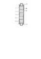
図1は、本発明の実施の形態1にかかる避雷器の概略構成を示す横断面図である。図1に示すように、避雷器10は、非直線抵抗素子1、押圧ばね2、端子電極3、第1被覆部4、絶縁支持体5、第2被覆部6を有して構成される。避雷器10は、第2被覆部6として、絶縁性の樹脂材料、例えばシリコーンゴムを用いたポリマー形避雷器である。
FIG. 1 is a cross-sectional view showing a schematic configuration of a lightning arrester according to a first embodiment of the present invention. As shown in FIG. 1, the
非直線抵抗素子1は、例えば、酸化亜鉛素子である。非直線抵抗素子1は、円柱形状を呈しており、円形面同士を接触させるように複数の非直線抵抗素子が積層される。押圧ばね2は、積層された非直線抵抗素子1の両端に設けられる。押圧ばね2は、積層された非直線抵抗素子1を両端から圧縮して、非直線抵抗素子1同士を密着させる。端子電極3は、積層された非直線抵抗素子1の両端に設けられる。 The
第1被覆部4は、図1に示すように、積層された非直線抵抗素子1の周囲と、端子電極3の一部の周囲を被覆する。第1被覆部4には、上述したように絶縁性の樹脂材料、例えばシリコーンゴムが用いられる。これら、非直線抵抗素子1、押圧ばね2、端子電極3および第1被覆部4で避雷器10の内部要素を構成する。 As shown in FIG. 1, the first covering
図2は、避雷器10の内部要素を拡大した部分拡大断面図である。図2に示すように、第1被覆部4は、その外周面4aがひだのない円滑面で形成されている。 FIG. 2 is a partially enlarged cross-sectional view in which the internal elements of the
内部要素の両端には、端末金具7が設けられる。端末金具7は、内部要素を挟み込むとともに、端子電極3と電気的に接続される。絶縁支持体5は、棒状形状を呈している。絶縁支持体5は、非直線抵抗素子1の積層方向に延伸するように配置される。また、絶縁支持体5は、内部要素の周り、すなわち第1被覆部4の外側に配置される。 Terminal fittings 7 are provided at both ends of the internal element. The terminal fitting 7 sandwiches an internal element and is electrically connected to the
絶縁支持体5は、端末金具7同士を連結し、避雷器10の機械的強度を向上させる。絶縁支持体5は、絶縁物であり比較的強度の高いガラス繊維強化プラスチック(FRP)等が用いられる。 The insulating support 5 connects the terminal fittings 7 to each other and improves the mechanical strength of the
第2被覆部6は、内部要素と絶縁支持体5とを一体的に被覆する。第2被覆部6には、その外周面にひだが形成されている。ひだは、非直線抵抗素子1の積層方向(以下、軸方向という。)に沿って略等間隔で複数個形成されている。第2被覆部6には、上述したように絶縁性の樹脂材料、例えばシリコーンゴムが用いられる。 The second covering
次に、避雷器10の製造方法について説明する。図3は、本発明の実施の形態1に係る避雷器の製造方法を説明するためのフローチャートである。 Next, the manufacturing method of the
まず、内部要素の一部を組み立てる(ステップS1)。より具体的には、積層された非直線抵抗素子1を押圧ばね2と端子電極3とで挟み込んだ状態で、図示しない冶具によって固定する。次に、組み立てられた内部要素の一部にプライマーを塗布する(ステップS2)。より具体的には、非直線抵抗素子1と端子電極3の表面にプライマーを塗布する。プライマーは、例えばシランカップリング剤である。シランカップリング剤を塗布してから、湿度30%〜80%の室温環境に約1時間放置することで、シランカップリング剤が遷移状態となる。 First, some of the internal elements are assembled (step S1). More specifically, the laminated
次に、シランカップリング剤が遷移状態となっている状態で、常圧下において、非直線抵抗素子1の周囲と端子電極3の一部の周囲に、絶縁性の樹脂材料を接触させて第1被覆部4を形成する(ステップS3)。これにより、積層された非直線抵抗素子1同士の隙間の周囲と、非直線抵抗素子1と端子電極3との隙間の周囲に、第1被覆部4が形成される。 Next, in a state where the silane coupling agent is in a transition state, an insulating resin material is brought into contact with the periphery of the
第1被覆部4を構成する絶縁性の樹脂材料としては、例えば、主剤と硬化剤の2液混合性で反応硬化タイプのシリコーンゴムを用いる。また、このシリコーンゴムは、室温での粘度が高粘度であるが、高温に加熱することで低粘度になるものを用いる。 As the insulating resin material constituting the first covering
ここで、第1被覆部4の常圧下での形成は、例えば、内部要素を低粘度のシリコーンゴム、例えば液状のシリコーンゴムにどぶ漬けしたり、内部要素を回転させながら液状のシリコーンゴムを内部要素の表面に垂らしたりすることで行われる。第1被覆部4は、例えば0.5〜1.0mmの厚さで形成される。 Here, the formation of the first covering
また、内部要素を金型で囲って第1被覆部4を形成する場合には、金型内部の成型部を真空状態にせずに、常圧のまま液状のシリコーンゴムを金型内部の成型部に注入すればよい。上述したように、第1被覆部4の外周面4aは円滑面で形成されているので、成型部の形状も複雑な形状にする必要がない。そのため、内部を真空状態にしない場合であっても、シリコーンゴムが成型部の隅々まで充填されやすい。なお、液状のシリコーンゴムは、付加反応(例えば加熱による反応)によって硬化する。 Further, when the first covering
次に、冶具を取り外し、内部要素を端末金具7で挟み込むとともに、端末金具7同士を絶縁支持体5で連結する(ステップS4)。端末金具7を絶縁支持体5で連結することで、端末金具7間が所定の距離に固定され、押圧ばね2による付勢力を非直線抵抗素子1に加えることができる。 Next, the jig is removed, the internal element is sandwiched between the terminal fittings 7, and the terminal fittings 7 are connected to each other by the insulating support 5 (step S4). By connecting the terminal fittings 7 with the insulating support 5, the terminal fittings 7 are fixed at a predetermined distance, and the urging force by the pressing spring 2 can be applied to the
次に、第1被覆部4の外周面にプライマーを塗布する(ステップS5)。ステップS2と同様に、プライマーとして、例えばシランカップリング剤を用いる。シランカップリング剤を塗布してから、湿度30%〜80%の室温環境に約1時間放置することで、シランカップリング剤が遷移状態となる。 Next, a primer is apply | coated to the outer peripheral surface of the 1st coating | coated part 4 (step S5). As in step S2, for example, a silane coupling agent is used as a primer. After applying the silane coupling agent, the silane coupling agent is brought into a transition state by leaving it in a room temperature environment of 30% to 80% humidity for about 1 hour.
次に、シランカップリング剤が遷移状態となっている状態で、内部要素と絶縁支持体5とを一体的に被覆するように第2被覆部6を形成する(ステップS6)。第2被覆部6を構成する絶縁性の樹脂材料としては、第1被覆部4と同様に、例えば、主剤と硬化剤の2液混合性で反応硬化タイプのシリコーンゴムを用いる。また、このシリコーンゴムは、室温での粘度が高粘度であるが、高温に加熱することで低粘度になるものを用いる。 Next, in a state where the silane coupling agent is in the transition state, the
第2被覆部6の形成は、内部要素と絶縁支持体5とを金型で囲い、金型内部の成型部に液状のシリコーンゴムを注入することで行われる。また、シリコーンゴムの注入時には、金型は予熱されているとともに、内部の成型部は真空状態とされている。また、シリコーンゴムの注入後は、注入口などを閉塞する。なお、液状のシリコーンゴムは、付加反応(例えば加熱による反応)によって硬化する。 Formation of the 2nd coating |
上述したように、第2被覆部6は、その外周面に複数個のひだが形成されている。そのため、金型の成型部の形状は、第1被覆部4を形成するための金型の成型部の形状に比べて複雑になる。しかしながら、成型部を真空状態にしてシリコーンゴムを注入すること、および予熱された金型によって温度が上昇し、シリコーンゴムの体積が膨張することによる内圧の上昇によって、複雑な形状の成型部の隅々までシリコーンゴムが充填されやすくなる。 As described above, the
以上説明したように、第1被覆部4と第2被覆部6とを同じ材料(本実施の形態ではシリコーンゴム)で構成したため、第1被覆部4と第2被覆部6との接着性の向上を図ることができる。したがって、第1被覆部4と第2被覆部6との間で界面剥離が発生するのを抑えることができ、避雷器10の信頼性の向上を図ることができる。 As described above, since the
また、シランカップリング剤が遷移状態となった状態で第2被覆部6が形成されるので、第1被覆部4と第2被覆部6との接着性のより一層の向上を図ることができる。したがって、第1被覆部4と第2被覆部6との間で内部で界面剥離が発生するのをより確実に抑えることができ、避雷器10の信頼性のより一層の向上を図ることができる。 Moreover, since the 2nd coating |
また、シランカップリング剤が遷移状態となった状態で第1被覆部4が形成されるので、第1被覆部4と非直線抵抗素子1との接着性の向上を図ることができる。したがって、第1被覆部4と非直線抵抗素子1との間で界面剥離が発生するのを抑えることができ、避雷器10の信頼性の向上を図ることができる。 Moreover, since the 1st coating |
また、第1被覆部4を常圧下で形成するので、積層された非直線抵抗素子1同士の隙間や、非直線抵抗素子1と端子電極3との隙間に、絶縁性の樹脂材料が侵入するのを抑えることができる。これにより、避雷器10の内部での接触不良を抑えることができ、部分放電の発生を抑えて、避雷器10の信頼性の向上を図ることができる。 Moreover, since the 1st coating |
また、積層された非直線抵抗素子1同士の隙間の周囲と、非直線抵抗素子1と端子電極3との隙間の周囲を、第1被覆部4が被覆するので、第2被覆部6を形成する際に、積層された非直線抵抗素子1同士の隙間や、非直線抵抗素子1と端子電極との隙間に絶縁性の樹脂材料が侵入するのを抑えることができる。 Moreover, since the 1st coating |
特に、第2被覆部6は、真空状態の成型部にシリコーンゴムを注入することや、内圧が上昇することにより、非直線抵抗素子1同士の隙間などにシリコーンゴムが侵入しやすい状態となるが、本実施の形態では、第1被覆部4によって、これらの侵入をより確実に抑えることができる。これにより、避雷器10の内部での接触不良を抑えことができ、部分放電の発生を抑えて、避雷器10の信頼性の向上を図ることができる。 In particular, the
また、絶縁支持体5が、内部要素の周り、すなわち第1被覆部4の外側に配置されるので、非直線抵抗素子1と絶縁支持体5との間に第1被覆部4が介在することとなる。これにより、非直線抵抗素子1と絶縁支持体5とが接触してしまうのを防ぐことができる。 In addition, since the insulating support 5 is disposed around the inner element, that is, outside the
特に、第1被覆部4を形成してから絶縁支持体5を配置することで、非直線抵抗素子1と絶縁支持体5とが接触したまま避雷器10が組み立てられてしまうことを防ぐことができる。これにより、避雷器10における電界集中などの不具合の発生を抑えることができる。 In particular, by disposing the insulating support 5 after forming the
以上のように、本発明にかかる避雷器は、電気機器の回路を保護する避雷器に有用であり、特に、内部要素を絶縁性の樹脂材料で被覆する避雷器に適している。 As described above, the lightning arrester according to the present invention is useful for a lightning arrester that protects a circuit of an electric device, and is particularly suitable for a lightning arrester that covers an internal element with an insulating resin material.
1 非直線抵抗素子
3 端子電極
4 第1被覆部
4a 外周面
5 絶縁支持体
6 第2被覆部
7 端末金具
10 避雷器DESCRIPTION OF
Claims (6)
Translated fromJapanese前記非直線抵抗素子の積層方向の両側に配置された一対の端子電極と、
前記非直線抵抗素子の周囲を絶縁性の樹脂材料で被覆して形成される第1被覆部と、
前記第1被覆部の周囲を絶縁性の樹脂材料で被覆して形成される第2被覆部と、を備え、
前記第1被覆部は、液状の樹脂材料を常圧下で前記直線抵抗素子の表面に接触させて形成されることを特徴とする避雷器。Laminated non-linear resistance elements;
A pair of terminal electrodes disposed on both sides of the non-linear resistance element in the stacking direction;
A first covering portion formed by coating the periphery of the non-linear resistance element with an insulating resin material;
A second covering portion formed by coating the periphery of the first covering portion with an insulating resin material,
The first covering part is formed by bringing a liquid resin material into contact with the surface of the linear resistance element under normal pressure.
前記絶縁支持体は、前記第1被覆部よりも外側に設けられ、
前記第2被覆部は、前記第1被覆部と前記絶縁支持体とを一体的に被覆することを特徴とする請求項1または2に記載の避雷器。A plurality of insulating elements arranged around the non-linear resistance element, each extending in the laminating direction, and further connecting the pair of terminal electrodes;
The insulating support is provided outside the first covering portion;
The lightning arrester according to claim 1 or 2, wherein the second covering portion integrally covers the first covering portion and the insulating support.
前記非直線抵抗素子の周囲を絶縁性の樹脂材料で被覆して第1被覆部を形成し、
前記第1被覆部の周囲を絶縁性の樹脂材料で被覆して第2被覆部を形成し、
前記第1被覆部の形成は、液状の樹脂材料を常圧下で前記非直線抵抗素子の表面に接触させる工程を含むことを特徴とする避雷器の製造方法。A method of manufacturing a lightning arrester comprising: a laminated non-linear resistance element; and a pair of terminal electrodes disposed on both sides of the non-linear resistance element in a laminating direction,
A first covering portion is formed by coating the periphery of the non-linear resistance element with an insulating resin material;
A second coating portion is formed by coating the periphery of the first coating portion with an insulating resin material;
The formation of the first covering portion includes a step of bringing a liquid resin material into contact with the surface of the non-linear resistance element under normal pressure.
前記第1被覆部と前記絶縁支持体とを一体的に被覆するように前記第2被覆部を形成することを特徴とする請求項4または5に記載の避雷器の製造方法。A plurality of insulating supports that extend in the stacking direction and connect the pair of terminal electrodes are arranged around the non-linear resistance element,
The method for manufacturing a lightning arrester according to claim 4 or 5, wherein the second covering portion is formed so as to integrally cover the first covering portion and the insulating support.
Priority Applications (1)
| Application Number | Priority Date | Filing Date | Title |
|---|---|---|---|
| JP2010245448AJP2012099615A (en) | 2010-11-01 | 2010-11-01 | Arrester and manufacturing method thereof |
Applications Claiming Priority (1)
| Application Number | Priority Date | Filing Date | Title |
|---|---|---|---|
| JP2010245448AJP2012099615A (en) | 2010-11-01 | 2010-11-01 | Arrester and manufacturing method thereof |
Publications (1)
| Publication Number | Publication Date |
|---|---|
| JP2012099615Atrue JP2012099615A (en) | 2012-05-24 |
Family
ID=46391208
Family Applications (1)
| Application Number | Title | Priority Date | Filing Date |
|---|---|---|---|
| JP2010245448APendingJP2012099615A (en) | 2010-11-01 | 2010-11-01 | Arrester and manufacturing method thereof |
Country Status (1)
| Country | Link |
|---|---|
| JP (1) | JP2012099615A (en) |
Citations (5)
| Publication number | Priority date | Publication date | Assignee | Title |
|---|---|---|---|---|
| JPS61284902A (en)* | 1985-06-11 | 1986-12-15 | 日本碍子株式会社 | Stationary connection of lightning arrestor element |
| JPS63312602A (en)* | 1987-06-16 | 1988-12-21 | Ngk Insulators Ltd | Lightning arrester |
| JPH053371A (en)* | 1991-06-25 | 1993-01-08 | Fuji Electric Co Ltd | Resin molding method for semiconductor laser device |
| JP2001023807A (en)* | 1999-07-09 | 2001-01-26 | Toshiba Corp | Arrester and method of manufacturing the same |
| JP2009111150A (en)* | 2007-10-30 | 2009-05-21 | Mitsubishi Electric Corp | Molded lightning arrester and manufacturing method thereof |
- 2010
- 2010-11-01JPJP2010245448Apatent/JP2012099615A/enactivePending
Patent Citations (5)
| Publication number | Priority date | Publication date | Assignee | Title |
|---|---|---|---|---|
| JPS61284902A (en)* | 1985-06-11 | 1986-12-15 | 日本碍子株式会社 | Stationary connection of lightning arrestor element |
| JPS63312602A (en)* | 1987-06-16 | 1988-12-21 | Ngk Insulators Ltd | Lightning arrester |
| JPH053371A (en)* | 1991-06-25 | 1993-01-08 | Fuji Electric Co Ltd | Resin molding method for semiconductor laser device |
| JP2001023807A (en)* | 1999-07-09 | 2001-01-26 | Toshiba Corp | Arrester and method of manufacturing the same |
| JP2009111150A (en)* | 2007-10-30 | 2009-05-21 | Mitsubishi Electric Corp | Molded lightning arrester and manufacturing method thereof |
Similar Documents
| Publication | Publication Date | Title |
|---|---|---|
| US12062502B2 (en) | Electrolytic capacitor and manufacturing method thereof | |
| KR101063137B1 (en) | Switch gear and manufacturing method | |
| JP6358405B2 (en) | Film for sealing, sealing method for electronic component mounting substrate, and film-covered electronic component mounting substrate for sealing | |
| US9312647B2 (en) | Connection of a first metal component to a covered second metal component | |
| EP3066170B1 (en) | Joining dissimilar materials of a capacitor using an epoxy resin composition | |
| CN118888943B (en) | Cover plate assembly and battery cell | |
| CN106463300A (en) | Method for the production a solid-insulated circuit-breaker pole, and solid-insulated circuit breaker pole | |
| CN101536116B (en) | Insulating support for high or medium voltage equipment, and device comprising such a support | |
| CN103339699B (en) | Thin film capacitor | |
| JP2012099616A (en) | Arrester and manufacturing method thereof | |
| JP2012099615A (en) | Arrester and manufacturing method thereof | |
| US20080136578A1 (en) | Method for Sheathing a Varsitor Block with an Electrically Insulating Sheath, as well as a Varsitor Block for a Surge Arrester | |
| KR101240078B1 (en) | Vacuum interrupter insulation device and method for manufacturing the same | |
| CN110164639B (en) | Arrester core, arrester and arrester processing method | |
| US10910135B2 (en) | Surge arrester and associated manufacturing method | |
| US20200373700A1 (en) | Wire connector | |
| JP2004071605A (en) | Arrester and manufacturing method thereof | |
| JPH07296657A (en) | Insulator type arrester | |
| CN223038659U (en) | A polymer high temperature resistant cross-linked automotive wire material structure | |
| CN204118173U (en) | A kind of battery terminal assembly | |
| CN202549524U (en) | Positive temperature coefficient (PTC) thermistor with stable performance | |
| JPH07192929A (en) | Molding material for electrical equipment, molding method and molded electrical equipment utilizing molding method | |
| JP2011514001A (en) | Solar cell module and manufacturing method thereof | |
| JP2004015991A (en) | Cable connecting part | |
| JP5805032B2 (en) | Power cable connecting component and manufacturing method thereof |
Legal Events
| Date | Code | Title | Description |
|---|---|---|---|
| A621 | Written request for application examination | Free format text:JAPANESE INTERMEDIATE CODE: A621 Effective date:20130529 | |
| A977 | Report on retrieval | Free format text:JAPANESE INTERMEDIATE CODE: A971007 Effective date:20140220 | |
| A131 | Notification of reasons for refusal | Free format text:JAPANESE INTERMEDIATE CODE: A131 Effective date:20140225 | |
| A02 | Decision of refusal | Free format text:JAPANESE INTERMEDIATE CODE: A02 Effective date:20140624 |