JP2012098892A - Position input device, position input method and program - Google Patents
Position input device, position input method and programDownload PDFInfo
- Publication number
- JP2012098892A JP2012098892AJP2010245586AJP2010245586AJP2012098892AJP 2012098892 AJP2012098892 AJP 2012098892AJP 2010245586 AJP2010245586 AJP 2010245586AJP 2010245586 AJP2010245586 AJP 2010245586AJP 2012098892 AJP2012098892 AJP 2012098892A
- Authority
- JP
- Japan
- Prior art keywords
- wind
- sound
- input device
- unit
- position input
- Prior art date
- Legal status (The legal status is an assumption and is not a legal conclusion. Google has not performed a legal analysis and makes no representation as to the accuracy of the status listed.)
- Pending
Links
Images


Landscapes
- Position Input By Displaying (AREA)
Abstract
Translated fromJapaneseDescription
Translated fromJapanese本発明は、位置入力装置、位置入力方法及びプログラムに関し、特に、ユーザが手指を触れることなく手軽にオブジェクトの位置を入力できる技術に関する。 The present invention relates to a position input device, a position input method, and a program, and more particularly to a technique that allows a user to easily input an object position without touching a finger.
従来より、ユーザが手足の不自由な人であっても、手指を触れることなく任意の操作情報を手軽に入力できる入力装置が要求されている。
このような要求に応えるべく、例えば、特許文献1には、次のような一連の処理を実行することで、ユーザが手指を触れることなく操作情報を入力する技術が開示されている。
即ち、特許文献1によれば、デバイスに設けられた圧力センサは、ユーザの口から吹き込まれた息を、空気圧の急激な変化として検出する。当該デバイスは、この圧力センサの検出結果に応じた所定の受信信号を生成して、受信機に伝送する。受信機は、受信信号に応じた操作情報を上位装置に入力させる。Conventionally, there has been a demand for an input device that allows a user to easily input arbitrary operation information without touching a finger even if the user is a handicapped person.
In order to meet such a demand, for example, Patent Document 1 discloses a technique for inputting operation information without touching a finger by executing the following series of processes.
That is, according to Patent Document 1, the pressure sensor provided in the device detects breath blown from the user's mouth as a sudden change in air pressure. The device generates a predetermined reception signal corresponding to the detection result of the pressure sensor, and transmits it to the receiver. The receiver causes the host device to input operation information corresponding to the received signal.
しかしながら、特許文献1に記載の技術では、1つの圧力センサのみを用いて空気圧の変化を検出している。
このため、特許文献1に記載の技術では、画面内の1点を押圧操作したか否かを示す操作情報、例えばソフトウェアボタンのオン又はオフを示す操作情報については、ユーザが手指を触れることなく手軽に入力することができる。
ところが、画面内でのオブジェクトの移動操作に関する操作情報、例えばカーソル等のオブジェクトの位置を、ユーザが手指を触れることなく入力することについては、特許文献1の技術をそのまま適用して実現することは非常に困難である。
ここで、受信機を複数配置して組み合わせることで、カーソル等のオブジェクの位置を、上位装置に入力させること自体は可能になるかもしれない。しかしながら、デバイスが各受信機に受信信号を伝送するためには、当該デバイス自体の方向を変えなければならない。よって、ユーザにとっては、手指を触れることなく手軽にオブジェクトの位置を入力できるとは言い難い。However, in the technique described in Patent Document 1, a change in air pressure is detected using only one pressure sensor.
For this reason, in the technique described in Patent Document 1, the operation information indicating whether or not one point in the screen is pressed, for example, the operation information indicating whether the software button is on or off, is not touched by the user. Easy input.
However, input of operation information related to the movement operation of an object on the screen, for example, the position of an object such as a cursor without touching a finger by a user, can be realized by applying the technique of Patent Document 1 as it is. It is very difficult.
Here, by arranging a plurality of receivers and combining them, it may be possible to cause the host device to input the position of an object such as a cursor. However, in order for a device to transmit a received signal to each receiver, the direction of the device itself must be changed. Therefore, it is difficult for the user to input the position of the object easily without touching the fingers.
本発明は、このような状況に鑑みてなされたものであり、ユーザが手指を触れることなく手軽にオブジェクトの位置を入力できることを目的とする。 The present invention has been made in view of such a situation, and an object of the present invention is to allow a user to easily input an object position without touching a finger.
上記目的を達成するため、請求項1に記載の発明は、
表示部におけるオブジェクトの移動の指示を入力するためにユーザにより発生された風について、複数位置における前記風に関する物理量をそれぞれ検出する風検出手段と、
前記風情報取得手段により検出された各物理量に基づいて、前記ユーザにより移動が指示された前記オブジェクトの移動先の位置を算出する移動先算出手段と、
を備える位置入力装置を提供する。In order to achieve the above object, the invention described in claim 1
Wind detection means for detecting physical quantities related to the wind at a plurality of positions for the wind generated by the user to input an instruction to move the object on the display unit;
Based on each physical quantity detected by the wind information acquisition means, a movement destination calculation means for calculating the position of the movement destination of the object instructed to move by the user;
A position input device is provided.
本発明の別の態様によると、上述した本発明の一態様に係る位置入力装置に対応する位置入力方法及びプログラムを提供する。 According to another aspect of the present invention, there is provided a position input method and program corresponding to the position input device according to one aspect of the present invention described above.
本発明によれば、ユーザが手指を触れることなく手軽にオブジェクトの位置を入力できる。 According to the present invention, the position of an object can be easily input without the user touching a finger.
以下、本発明の位置入力装置の実施形態として、第1実施形態と第2実施形態について、その順番で個別に説明する。 Hereinafter, as an embodiment of the position input device of the present invention, the first embodiment and the second embodiment will be described individually in that order.
[第1実施形態]
図1は、本発明の第1実施形態に係る位置入力装置の外観構成を示す斜視図である。
位置入力装置10は、例えばフォトフレームにより構成され、少なくともオブジェクト(第1実施形態ではカーソルであるとする)を移動させる、又は、オブジェクトに関連付けられたアプリケーションを操作するGUI(Graphical User Interface)が実現可能になっている。
この場合、ユーザは、マウス等の入力機器を用いずに、自身の口から吹きかける息を用いて、カーソルの移動指示を入力する。即ち、ユーザは、手指を触れることなく手軽にカーソルの位置を入力できる。
換言すると、位置入力装置10は、ユーザにより吹きかけられた息により生ずる風を検出することによって、ユーザにより入力されるカーソルの移動指示を認識し、当該移動指示に従った処理を実行する。
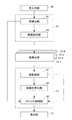
位置入力装置10は、このような処理の実行を可能にすべく、筺体11と、表示部12と、音入力部13と、を備えている。
筺体11は、矩形状に形成され、それぞれに分割可能な略同形状の基台11aと、上部カバー11bと、を備えている。なお、上部カバー11bの各辺の中央周辺に形成された孔14−1,14−2,14−3,14−4については、図3を参照して後述する。[First Embodiment]
FIG. 1 is a perspective view showing an external configuration of the position input device according to the first embodiment of the present invention.
The
In this case, the user inputs an instruction to move the cursor using a breath blown from his / her mouth without using an input device such as a mouse. That is, the user can easily input the position of the cursor without touching the fingers.
In other words, the
The
The
図2は、図1の位置入力装置10の筺体11の基台11aの外観構成を示す斜視図である。
基台11aは、矩形状に形成され、液晶ディスプレイ等で構成される表示部12と、マイクロフォン等で構成される音入力部13と、複数の風検出部15−1,15−2,15−3,15−4と、が配置されている。
具体的には、基台11aの中央部には表示部12が配置されている。換言すると、表示部12は、基台11aの上面に配置されており、基台11aに上部カバー11bが被されることによって、図1に示すように筺体11の内方に配置されることになる。
また、基台11aの外縁部には、音入力部13と、複数の風検出部15−1,15−2,15−3,15−4とがそれぞれ配置されている。
換言すると、音入力部13は基台11aの外縁部のうち、1つの長辺部の中央付近に配置されている。
複数の風検出部15−1,15−2,15−3,15−4の各々は、基台11aの外縁部の各辺部の略中央に配置されている。2 is a perspective view showing an external configuration of the
The
Specifically, the
A
In other words, the
Each of the plurality of wind detectors 15-1, 15-2, 15-3, and 15-4 is disposed at the approximate center of each side of the outer edge of the
図3は、図1の位置入力装置10の筺体11の上部カバー11bの外観構成を示す斜視図である。
上部カバー11bには、上述したように、風検出部15−1,15−2,15−3,15−4のそれぞれを外方と挿通可能な孔14−1,14−2,14−3,14−4がそれぞれ形成されている。
なお、以下、風検出部15−1,15−2,15−3,15−4を個々に区別する必要がない場合、これらをまとめて「風検出部15」と呼ぶ。また、風検出部15と呼んでいる場合、孔14−1,14−2,14−3,14−4をまとめて「孔14」と呼ぶ。FIG. 3 is a perspective view showing an external configuration of the
As described above, the
Hereinafter, when it is not necessary to individually distinguish the wind detection units 15-1, 15-2, 15-3, and 15-4, they are collectively referred to as “
風検出部15は、風に関する物理量を検出できれば足り、その構成は特に限定されないが、本実施形態では図4に示すような風力センサとして構成されている。
図4は、図1乃至図3の位置入力装置10に設けられる風検出部15として適用される風力センサの内部構成を示す斜視図である。
風検出部15は、第1実施形態では図4に示す構成の風力センサにより構成されている。即ち、第1実施形態の風検出部15は、センサ筺体16と、ファン17と、フォトカプラ18と、を備えている。
センサ筺体16は、長方形状を有し、外方からの気体が進入可能な入口孔部19と、入口孔部19から進入した気体を外方へ排出可能な出口孔部20と、がそれぞれ形成されている。
ファン17は、多翼状のシロッコファンにより構成され、入口孔部19から気体が進入することに伴い、回転可能に軸支されている。
フォトカプラ18は、回転したファン17の外周形状の翼の凹凸の繰り返しを、風検出部15の検出結果(風力量)を示すパルス信号に変換して出力する。The
FIG. 4 is a perspective view showing an internal configuration of a wind sensor applied as the
In the first embodiment, the
The
The
The
位置入力装置10(より正確には後述する図5のCPU51)は、フォトカプラ18から出力されたパルス信号に基づいてファン17の回転速度を検出し、当該回転速度に基づいて、風検出部15により検出された風力量を取得する。
即ち、位置入力装置10は、各風検出部15−1,15−2,15−3,15−4のそれぞれのフォトカプラ18から出力されたパルス信号に基づいて、各風検出部15−1,15−2,15−3,15−4の各々により検出された風力量をそれぞれ取得する。
ここで、位置入力装置10に設けられた表示部12は、一般的には、その長辺方向を左右方向として、その短辺方向を上下方向として、画像を表示する。そこで、以下、表示部12の長辺方向、即ち、図1乃至図3において筺体11の外縁部の長辺部(風検出部15−2,15−4が配置される部)と略水平な方向を、「左右方向」と呼ぶ。また、左右方向と垂直な方向、即ち、図1乃至図3において筺体11の外縁部の短辺部(風検出部15−1,15−3が配置される部)と略水平な方向を、「垂直方向」と呼ぶ。
この場合、位置入力装置10は、風検出部15−1と15−3とにより検出された各々の風力量の差分に基づいて、風の左右方向の成分を推定することができる。同様に、位置入力装置10は、風検出部15−2と15−4とにより検出された各々の風力量の差分に基づいて、風の上下方向の成分を推定することができる。
そこで、位置入力装置10は、推定した風の左右方向及び上下方向の各成分に基づいて、カーソルの移動先の位置を算出する。
なお、このような位置入力装置10により、カーソルの移動先の位置が算出されるまでに実行される一連の処理を、以下、「移動先算出処理」と呼ぶ。The position input device 10 (more precisely, a
That is, the
Here, the
In this case, the
Accordingly, the
Note that a series of processes executed until the position of the cursor destination is calculated by the
図5は、このような移動先算出処理を実行可能な図1の位置入力装置10のハードウェアの構成を示すブロック図である。 FIG. 5 is a block diagram showing a hardware configuration of the
位置入力装置10は、上述した表示部12、音入力部13、及び風検出部15−1乃至15−4に加えてさらに、CPU(Central Processing Unit)51と、ROM(Read Only Memory)52と、RAM(Random Access Memory)53と、バス54と、入出力インターフェース55と、操作部56と、音出力部57と、通信部58と、ドライブ59と、を備えている。 In addition to the
CPU51は、ROM52に記録されているプログラム、又は、RAM53にロードされたプログラムに従って各種の処理を実行する。
RAM53にはまた、CPU51が各種の処理を実行する上において必要なデータ等も適宜記憶される。
また、RAM53は、DRAM(Dynamic Random Access Memory)等で構成され、ドライブ59から出力された画像のデータを一時的に記憶する。また、RAM53は、各種画像処理に必要な各種データ、例えば、画像のデータ、各種フラグの値、閾値等も記憶する。The
The
The
例えば本実施形態では、後述する図6の音検出部81、感度設定部82、風取得部91、移動先算出部92及びカーソル制御部93の各機能を実現するプログラムが、ROM52やドライブ61に記憶されている。従って、CPU51が、これらのプログラムに従った処理を実行することで、後述する図6の音検出部81、感度設定部82、風取得部91、移動先算出部92及びカーソル制御部93の各機能を実現することができる。 For example, in the present embodiment, programs for realizing the functions of a
CPU51、ROM52、及びRAM53は、バス54を介して相互に接続されている。このバス54にはまた、入出力インターフェース55も接続されている。入出力インターフェース55には、上述した表示部12、音入力部13、及び風検出部15−1乃至15−4に加えてさらに、操作部56、音出力部57、及び通信部58が接続されている。 The
操作部56は、電源釦、モードSW(Switch)釦等各種釦等で構成され、ユーザの指示操作を受け付ける。 The
音出力部57は、スピーカ等で構成され、効果音等、各種音を出力する。 The
通信部58は、図示せぬ他の装置との間で行う各種通信(インターネット等のネットワークを介する通信を含む)も制御する。 The
入出力インターフェース55にはまた、必要に応じてドライブ59が接続され、磁気ディスク、光ディスク、光磁気ディスク、或いは半導体メモリ等よりなるリムーバブルメディア71が適宜装着される。
ドライブ59によってリムーバブルメディア71から読み出されたプログラムは、必要に応じてRAM53にインストールされる。また、リムーバブルメディア71は、RAM53に記憶されている画像データ等の各種データも、RAM53と同様に記憶することができる。A
The program read from the removable medium 71 by the
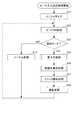
図6は、このような位置入力装置10の機能的構成のうち、移動先算出処理を実行するための機能的構成を示す機能ブロック図である。
図6においては、図5の位置入力装置10の構成のうち、表示部12と、音入力部13と、風検出部15−1乃至15−4と、CPU51と、風検出部15が図示されている。
CPU51は、音検出部81と、感度設定部82と、風取得部91と、移動先算出部92と、カーソル制御部93と、を備えている。FIG. 6 is a functional block diagram showing a functional configuration for executing the destination calculation process among the functional configurations of the
6, the
The
音検出部81は、ユーザにより吹きかけられた息の音を音入力部13を介して検出する。
具体的には、音入力部13は、ユーザが位置入力装置10に対して息を吹きかけることにより生ずる表示部12付近で発生した息の音を入力し、音声データに変換して音検出部81に供給する。音検出部81は、当該音声データに基づいて、息の音の音量及び種別を検出する。
音検出部81が検出する息の音の種別としては、例えば本実施形態では、ユーザの口から息が高圧で吹き出す時に発生する音、即ち、いわゆる“風切音”と呼ばれる、10khz成分が多い非常に高い周波数の音が存在する。風切音は、口を思いっきりすぼめてかなり強く息を吹き出した時、又は歯を食いしばって息を吹き出した時に出やすい種別の音である。
また、音検出部81が検出する息の音の種別としては、例えば本実施形態では、ユーザが位置入力を行う際に発生させる息の音、即ちいわゆる“吹かれノイズ”と呼ばれる、風切音とは異なる周波数帯の音が存在する。
本実施形態では、ユーザは、カーソルの移動先の位置の入力(以下、「カーソル移動先入力」と呼ぶ)をする際には、吹かれノイズを発生させるように息を吹きかけるものとする。また、ユーザは、カーソルが指し示すアイコン等の選択の指示、具体的には、当該アイコン等の移動、アイコン等に関連付けられたアプリケーションの起動、終了等の操作の入力をする際には、いわゆるマウスのクリック操作に対応する入力(以下、「クリック入力」と呼ぶ)をする際には、風切音を発生させるように息を吹きかけるものとする。
この場合、吹かれノイズと風切音とは上述したように周波数帯が相異なるため、音検出部81は、周波数帯で切り分けることにより、ほぼ誤検出することなく、吹かれノイズと風切音との各々の種別を検出することが可能になる。よって、風切音によるカーソル移動先入力と、吹かれノイズによるクリック入力とが、混同して検知されることがほぼなくなる。
音検出部81は、このようにして検出した息の音の音量及び種別を示す情報(以下、「音検出情報」と呼ぶ)を生成し、感度設定部82及びカーソル制御部93に供給する。The
Specifically, the
As types of breath sounds detected by the
As a type of breath sound detected by the
In the present embodiment, when inputting the position of the cursor movement destination (hereinafter referred to as “cursor movement destination input”), it is assumed that the user blows to generate blowing noise. In addition, when the user inputs an instruction to select an icon or the like pointed to by the cursor, specifically, an operation such as movement of the icon or the like, activation or termination of an application associated with the icon or the like, a so-called mouse is input. When performing an input corresponding to the click operation (hereinafter referred to as “click input”), it is assumed to blow to generate a wind noise.
In this case, since the blowing noise and the wind noise are different from each other in the frequency band as described above, the
The
感度設定部82は、音検出部81から供給された音検出情報のうち、息の音の音量に応じて各風検出部15−1乃至15−4における風力量の検出の感度をそれぞれ設定する。
具体的には、後述の図9の音入力処理において詳述するが、息の音の種別のうち、吹かれノイズの音量に応じて、風検出部15−1乃至15−4における風力量の検出の感度がそれぞれ設定される。The
Specifically, as will be described in detail in the sound input process of FIG. 9 described later, according to the volume of the blowing noise among the types of breath sounds, the wind amount of the wind detectors 15-1 to 15-4 is determined. Detection sensitivity is set for each.
風検出部15−1乃至15−4の各々は、感度設定部82により設定された感度で、ユーザが位置入力装置10に対して息を吹きかけることにより生ずる風の風力量をそれぞれ検出する。
各風検出部15−1乃至15−4の各々は、検出した各風の風力量を示す情報(以下、「風情報」と呼ぶ)を風取得部91に供給する。本実施形態では、図4を参照して上述したように、フォトカプラ18から出力されるパルス信号が、風情報として風取得部91に供給される。Each of the wind detection units 15-1 to 15-4 detects the amount of wind force generated by the user blowing on the
Each of the wind detection units 15-1 to 15-4 supplies information (hereinafter referred to as “wind information”) indicating the detected wind amount of each wind to the
風取得部91は、各風検出部15−1乃至15−4の各々から供給された各風情報を取得し、移動先算出部92及びカーソル制御部93に供給する。 The
移動先算出部92は、風取得部91から供給された各風情報に基づいて、表示部12におけるカーソルの移動先の位置を算出する。
具体的には、表示部12の上下方向に対向して配置された風検出部15−2及び風検出部15−4の各風情報に基づいて、風検出部15−2と風検出部15−4との間の各風力量の差分、即ち、上下方向の風の成分が求められる。当該差分に基づいて、即ち、上下方向の風の成分に基づいて、上下方向のカーソルの移動先の位置が算出される。
また、表示部12の左右方向に対向して配置された風検出部15−1及び風検出部15−3の各風情報に基づいて、風検出部15−1と風検出部15−3との間の各風力量の差分、即ち、左右方向の風の成分が求められる。当該差分に基づいて、即ち、左右方向の風の成分に基づいて、左右方向のカーソルの移動先の位置が算出される。
移動先算出部92は、算出したカーソルの移動先の位置を示す情報(以下、「カーソル移動先情報」と呼ぶ)をカーソル制御部93に供給する。The movement
Specifically, the wind detection unit 15-2 and the
Further, based on the wind information of the wind detection unit 15-1 and the wind detection unit 15-3 arranged to face the left and right direction of the
The movement
カーソル制御部93は、移動先算出部92からカーソル移動先情報が供給された場合、ユーザによりカーソル移動先入力がなされたものとして、当該カーソル移動先情報に基づき、表示部12におけるカーソルの位置を移動させる制御を実行する。
また、カーソル制御部93は、音検出部81から供給された音検出情報に含まれる息の音の種別が、風切音であった場合、ユーザによりクリック入力がなされたものとして、表示部12におけるカーソルをクリックする制御を実行する。When the cursor movement destination information is supplied from the movement
In addition, the
次に、図7を参照して、このような図6の機能的構成を有する位置入力装置10が、カーソル移動入力等のユーザからの指示の入力を受け付け、当該指示に従った処理を実行するまでの一連の処理(以下、「ユーザ入力対応処理」と呼ぶ)について説明する。 Next, referring to FIG. 7,
図7は、ユーザ入力対応処理の流れを説明するフローチャートである。
例えば、ユーザ入力対応処理は、本実施形態では、操作部56の電源釦の押下操作等、ユーザが位置入力を開始する指示操作を操作部56に対して行った場合、その指示操作を契機として開始される。FIG. 7 is a flowchart for explaining the flow of the user input handling process.
For example, in the present embodiment, the user input handling process is triggered by the instruction operation when the user performs an instruction operation for starting position input, such as a pressing operation of the power button of the
図7のステップS11において、CPU51は、全システムを初期設定するためのイニシャライズ処理を行う。具体的には例えば、CPU51は、後述するモードSW処理において設定されるモードの初期値として通常モードを設定する。
また例えば、CPU51は、後述する音入力処理において設定される風力センサ15−1乃至15−4の感度を初期状態に設定すると共に、感度アップフラグを0に設定する。
ここで、感度アップフラグとは、風力センサ15−1乃至15−4の感度が上げられたか否かを示すフラグである。風力センサ15−1乃至15−4の感度が上げられると、感度アップフラグは「1」に設定される(後述する図9のステップS55参照)。一方、風力センサ15−1乃至15−4の感度が下げられる(本実施形態では、感度は2値であって、低値が基準値とされているので、「感度が戻される」とも表現する)と、感度アップフラグは「0」に設定される(後述する図9のステップS58参照)。
それ以外にも様々な初期設定が行われるが、詳細の説明は省略する。In step S11 of FIG. 7, the
Further, for example, the
Here, the sensitivity up flag is a flag indicating whether or not the sensitivity of the wind sensors 15-1 to 15-4 has been increased. When the sensitivity of the wind sensors 15-1 to 15-4 is increased, the sensitivity increase flag is set to “1” (see step S55 in FIG. 9 described later). On the other hand, the sensitivity of the wind sensors 15-1 to 15-4 is lowered (in this embodiment, the sensitivity is binary, and the low value is the reference value, so it is also expressed as “sensitivity is returned”). ) And the sensitivity up flag is set to “0” (see step S58 in FIG. 9 described later).
Various other initial settings are made, but detailed description thereof is omitted.
ステップS12において、CPU51は、モードSW釦のSW操作があった場合に、通常モード又は風向モードの何れかのモードへの反転を行うまでの一連の処理(以下、「モードSW処理」と呼ぶ)を実行する。
モードSW処理の詳細については図8を参照して後述する。
ステップS12のモードSW処理が終了すると、処理はステップS13に進む。In step S12, the
Details of the mode SW process will be described later with reference to FIG.
When the mode SW process in step S12 ends, the process proceeds to step S13.
ステップS13において、CPU51は、現在のモードが風向モードであるか否かを判定する。 In step S13, the
ここで、位置入力装置10の動作モードとして、本実施形態では、風向モードと通常モードの2種類が存在する。風向モードと通常モードの一方から他方への切り替えは、ステップS12のモードSW処理において、モードSW釦に対する押下操作によって行われる。 Here, in the present embodiment, there are two types of operation modes of the position input device 10: a wind direction mode and a normal mode. Switching from one of the wind direction mode and the normal mode to the other is performed by pressing the mode SW button in the mode SW process of step S12.
風向モードとは、表示部12に対するGUI操作が、ユーザにより吹きかけられる息によって行われる場合の動作モードをいう。
例えば、風向モードでは、表示部12におけるカーソルの移動先を、ユーザが息を吹きかける操作をすることによって、位置入力装置10が、当該操作を認識して、カーソルを移動先まで移動させる(そのように表示部12に表示させる)ように動作する。
また例えば、風向モードでは、カーソルが指し示すアイコン等の選択指示を、ユーザが風切音を出すように息を吹きかける操作をすることによって、位置入力装置10が、当該操作を認識して、アイコン等の選択をするように動作する。具体的には、アイコン等の選択により、アイコン等の移動、アイコン等に関連付けられたアプリケーションの起動、終了等の操作が行われる。The wind direction mode refers to an operation mode when a GUI operation on the
For example, in the wind direction mode, the
Further, for example, in the wind direction mode, the
一方、通常モードとは、表示部12に対するGUI操作がマウス等の入力機器を用いて行われる場合の動作モードをいう。
例えば、通常モードでは、表示部12におけるカーソルの移動先を、ユーザがマウスを移動させる操作をすることにより、位置入力装置10が、当該操作を認識して、カーソルを移動先まで移動させる(そのように表示部12に表示させる)ように動作する。
また例えば、通常モードでは、カーソルが指し示すアイコン等の選択指示を、ユーザがマウスのクリック操作により行い、位置入力装置10が、当該クリック操作を認識して、アイコン等の選択をするように動作する。
このような、通常モード時における位置入力装置10のCPU51が実行する処理を、以下、「ノーマル処理」と呼ぶ。On the other hand, the normal mode refers to an operation mode when a GUI operation on the
For example, in the normal mode, the
Further, for example, in the normal mode, the user performs an instruction to select an icon or the like pointed to by the cursor by a click operation of the mouse, and the
Such processing executed by the
従って、現在のモードが風向モードでない場合、即ち、通常モードの場合、ステップS13においてNOであると判定されて、処理はステップS14に進む。
ステップS14において、CPU51は、ノーマル処理を行う。
その後処理は、ステップS12に戻される。
即ち、本実施形態では、ステップS12のモードSW処理で現在のモードが風向モードに切り替えられるまでの間、ステップS12、ステップS13:NO、及びステップS14のループ処理が繰り返し実行されて、ノーマル処理がその間継続して実行される。Therefore, if the current mode is not the wind direction mode, that is, if it is the normal mode, it is determined NO in step S13, and the process proceeds to step S14.
In step S14, the
Thereafter, the process returns to step S12.
That is, in this embodiment, until the current mode is switched to the wind direction mode in the mode SW process of step S12, the loop process of step S12, step S13: NO, and step S14 is repeatedly executed to perform the normal process. During that time, it is executed continuously.
これに対し、現在のモードが風向モードである場合、ステップS13においてYESであると判定されて、処理はステップS15に進む。 On the other hand, when the current mode is the wind direction mode, it is determined as YES in Step S13, and the process proceeds to Step S15.
ステップS15において、CPU51は、音入力部13に入力された音の音量に応じて風力センサ15−1乃至15−4の感度の設定を行うまでの一連の処理(以下、「音入力処理」と呼ぶ)を実行する。
音入力処理の詳細については、図9を参照して後述する。
ステップS15の音入力処理が終了すると、処理はステップS16に進む。In step S15, the
Details of the sound input processing will be described later with reference to FIG.
When the sound input process in step S15 ends, the process proceeds to step S16.
ステップS16において、CPU51は、図6の機能的構成に基づく各種機能を発揮することで、図6を参照して上述した移動先算出処理を実行する。
移動先算出処理の詳細については、図10を参照して後述する。
ステップS16の移動先算出処理が終了すると、処理はステップS17に進む。In step S <b> 16, the
Details of the destination calculation process will be described later with reference to FIG.
When the movement destination calculation process in step S16 ends, the process proceeds to step S17.
ステップS17において、CPU51は、音入力部13に入力された音の種別に応じてクリック入力を検出するまでの一連の処理(以下、「クリック検出処理」と呼ぶ)を実行する。
クリック検出処理の詳細については、図11を参照して後述する。
ステップS17のクリック検出処理が終了すると、処理はステップS18に進む。In step S <b> 17, the
Details of the click detection process will be described later with reference to FIG.
When the click detection process in step S17 ends, the process proceeds to step S18.
ステップS18において、CPU51は、発音処理を実行する。
発音処理とは、所定の音を音出力部57から発生させる処理をいう。例えば、ステップS17のクリック検出処理においてクリック入力が検出された場合、マウスのクリック音(録音された音でもよいし、模擬的に作り出した音でもよい)を音出力部57から出力する処理が、発音処理の一部として実行される。
このようなステップS18の発音処理が終了すると、処理は、ステップS12に戻され、それ以降の処理が実行される。
即ち、本実施形態では、ステップS12の処理で現在のモードが通常モードに切り替えられるまでの間、ステップS12、ステップS13:YES、ステップS15乃至ステップS18のループ処理が繰り返し実行されて、風向モードによる処理、例えば移動先算出処理等がその間継続して実行される。In step S18, the
The sound generation process is a process for generating a predetermined sound from the
When the sound generation process in step S18 is completed, the process returns to step S12, and the subsequent processes are executed.
That is, in this embodiment, until the current mode is switched to the normal mode in the process of step S12, the loop process of step S12, step S13: YES, step S15 to step S18 is repeatedly executed, and the wind direction mode is used. A process, for example, a movement destination calculation process is continuously executed during that time.
以上、図7を参照して、ユーザ入力対応処理の流れについて説明した。
次に、図8を参照して、図7のユーザ入力対応処理のうち、ステップS12のモードSW処理の詳細な流れについて説明する。The flow of user input handling processing has been described above with reference to FIG.
Next, with reference to FIG. 8, the detailed flow of the mode SW process of step S12 in the user input handling process of FIG. 7 will be described.
図8は、モードSW処理の流れを説明するフローチャートである。
上述したように、CPU51により、図7のステップS11の処理でイニシャライズが行われると、処理はステップS12に進み、モードSW処理として次のような処理が実行される。FIG. 8 is a flowchart for explaining the flow of the mode SW process.
As described above, when initialization is performed by the
即ち、図8のステップS31において、CPU51は、ユーザによりモードSW釦(操作部56の一部)のSW操作があったか否かを判定する。
ユーザがモードSW釦の押下操作をしていない状態では、SW操作が行われないため、ステップS31においてNOであると判定されて、モードSW処理は終了となるThat is, in step S31 of FIG. 8, the
Since the SW operation is not performed when the user has not pressed the mode SW button, it is determined as NO in step S31, and the mode SW process ends.
CPU51により、ユーザによりモードSW釦のSW操作があったと判定された場合、ステップS31においてYESであると判定されて、処理はステップS32に進む。 When it is determined by the
ステップS32において、CPU51はモードの反転を行う。
モードの反転とは、位置入力装置10の動作モードとして、通常モードと風向モードとのうち、一方から他方に反転するように切り替える処理をいう。例えば、現在のモードが通常モードである場合に、モードSW釦のSW操作がなされた場合には、通常モードから風向モードに切り替わる。一方、現在のモードが風向モードである場合に、モードSW釦のSW操作がなされた場合には、風向モードから通常モードに切り替わる。In step S32, the
The inversion of the mode refers to a process of switching the normal mode and the wind direction mode so as to invert from one to the other as the operation mode of the
ステップS32の処理が終了すると、モードSW処理が終了となる。即ち、図7のステップS12の処理は終了し、処理はステップS13に進む。当該モードSW処理で、風向モードに切り替えられた場合、ステップS13においてYESであると判定されて、処理はステップS15の音入力処理に進む。 When the process of step S32 ends, the mode SW process ends. That is, the process of step S12 in FIG. 7 ends, and the process proceeds to step S13. If the mode SW process is switched to the wind direction mode, it is determined as YES in step S13, and the process proceeds to the sound input process in step S15.
そこで、以下、図9を参照して、図7のユーザ入力対応処理のうち、ステップS15の音入力処理の詳細な流れについて説明する。 Therefore, with reference to FIG. 9, a detailed flow of the sound input process of step S15 in the user input handling process of FIG. 7 will be described below.
図9は、音入力処理の流れを説明するフローチャートである。
上述したように、CPU51により、現在のモードが風向モードであると判定されると、処理はステップS15に進み、音入力処理として次のような処理が実行される。FIG. 9 is a flowchart for explaining the flow of sound input processing.
As described above, when the
即ち、図9のステップS51において、音検出部81は、ユーザにより吹きかけられた息の音の音量及び種別を、音入力部13を介して検出する。
そして、音検出部81は、検出された音の音量及び種別を示す音検出情報を生成して、感度設定部82及びカーソル制御部93に供給する。That is, in step S51 of FIG. 9, the
The
ステップS52において、感度設定部82は、感度アップフラグは「0」であるか否かを判定する。
上述したとおり、感度アップフラグは、風力センサ15−1乃至15−4の感度が上げられたか又は下げられたのか(戻されたか)を示すフラグである。従って、この処理では、感度アップフラグが判定されることにより、現在の風力センサ15−1乃至15−4の感度が高い状態であるのか否かを判別することができる。
例えば、現在の風力センサ15−1乃至15−4の感度が低い状態の場合には、感度アップフラグは「0」になっており、このような場合、ステップS52においてYESであると判定されて、ステップS53乃至S55の処理が実行されて、必要に応じて感度が上げられる。
これに対して、例えば、現在の風力センサ15−1乃至15−4の感度が高い状態の場合には、感度アップフラグは「1」になっており、このような場合、ステップS52においてNOであると判定されて、ステップS56乃至S58の処理が実行されて、必要に応じて感度が下げられる(戻される)。
以下、感度アップフラグが「0」になっている場合に実行されるステップS53乃至S55の処理と、感度アップフラグが「1」になっている場合に実行されるステップS56乃至S58の処理との各々について、その順番に個別に説明する。In step S52, the
As described above, the sensitivity up flag is a flag indicating whether the sensitivity of the wind sensors 15-1 to 15-4 has been increased or decreased (returned). Therefore, in this process, it is possible to determine whether or not the sensitivity of the current wind sensors 15-1 to 15-4 is high by determining the sensitivity up flag.
For example, when the current wind sensor 15-1 to 15-4 is in a low sensitivity state, the sensitivity up flag is “0”. In such a case, it is determined as YES in step S52. Steps S53 to S55 are executed, and the sensitivity is increased as necessary.
On the other hand, for example, when the sensitivity of the current wind sensors 15-1 to 15-4 is high, the sensitivity up flag is “1”. In such a case, NO is determined in step S52. When it is determined that there is, the processing of steps S56 to S58 is executed, and the sensitivity is lowered (returned) as necessary.
Hereinafter, steps S53 to S55 executed when the sensitivity up flag is “0” and steps S56 to S58 executed when the sensitivity up flag is “1”. Each will be described individually in that order.
先ず、感度アップフラグが「0」になっている場合には、ステップS52においてYESであると判定されて、処理はステップS53に進む。
ステップS53において、感度設定部82は、吹かれノイズは−6dB以上であるか否かを判定する。
吹かれノイズが−6dB未満であると判定された場合には、ステップS53においてNOであると判定されて、音入力処理が終了となる。
即ち、感度アップフラグが「0」であり、かつ、音入力部13を通じて取得された音の音量が閾値より小さい場合には、感度設定部82は、ユーザによる位置入力操作が行われていないと判断して、各風力センサ15−1乃至15−4の感度を下げたままの状態にする。First, when the sensitivity up flag is “0”, it is determined as YES in Step S52, and the process proceeds to Step S53.
In step S53, the
If it is determined that the blown noise is less than −6 dB, it is determined NO in step S53, and the sound input process ends.
That is, when the sensitivity up flag is “0” and the volume of the sound acquired through the
これに対して、吹かれノイズが−6dB以上であると判定された場合には、ステップS53においてYESであると判定されて、処理はステップS54に進む。 On the other hand, if it is determined that the blowing noise is -6 dB or more, it is determined as YES in step S53, and the process proceeds to step S54.
ステップS54において、感度設定部82は、風力センサ15−1乃至15−4の感度を上げる。
即ち、感度アップフラグが「0」であるにも関わらず、音入力部13を通じて取得された音の音量が閾値より大きい場合には、感度設定部82は、ユーザによる位置入力操作が行われ始めたと判断して、各風力センサ15−1乃至15−4の感度を上げる。In step S54, the
That is, when the sound volume acquired through the
ステップS55において、感度設定部82は、感度アップフラグを「1」に設定する。
これにより、音入力処理が終了する。In step S55, the
This completes the sound input process.
以上、現在の風力センサ15−1乃至15−4の感度が低い状態の場合の処理、即ち、感度アップフラグが「0」になっており、ステップS52においてYESであると判定された後に実行されるステップS53乃至S55の処理について説明した。
次に、現在の風力センサ15−1乃至15−4の感度が高い状態の場合の処理、即ち、感度アップフラグが「1」になっている場合の処理について説明する。このような場合、ステップS52においてNOであると判定されて、処理はステップS56に進む。As described above, the processing when the sensitivity of the current wind sensors 15-1 to 15-4 is low, that is, the sensitivity up flag is “0”, and is executed after it is determined as YES in step S52. The process of steps S53 to S55 has been described.
Next, processing when the sensitivity of the current wind sensors 15-1 to 15-4 is high, that is, processing when the sensitivity up flag is “1” will be described. In such a case, it is determined as NO in Step S52, and the process proceeds to Step S56.
ステップS56において、感度設定部82は、吹かれノイズは−20dB以下であるか否かを判定する。
吹かれノイズが−20dBより大きいと判定された場合には、ステップS56においてNOであると判定されて、音入力処理が終了となる。
即ち、感度アップフラグが「1」であり、かつ、音入力部13を通じて取得された音の閾値以上の音量が発生している場合には、感度設定部82は、ユーザによる位置入力操作が継続して行われていると判断して、各風力センサ15−1乃至15−4の感度を上げた状態を継続させる。In step S56, the
If it is determined that the blown noise is greater than −20 dB, it is determined NO in step S56, and the sound input process ends.
That is, when the sensitivity up flag is “1” and the sound volume is higher than the threshold value of the sound acquired through the
これに対して、吹かれノイズが−20dB以下であると判定された場合には、ステップS56においてYESであると判定されて、処理はステップS57に進む。 On the other hand, if it is determined that the blowing noise is -20 dB or less, it is determined as YES in step S56, and the process proceeds to step S57.
ステップS57において、感度設定部82は、風力センサ15−1乃至15−4の感度を初期状態に戻す。
即ち、感度アップフラグが「1」であるにも関わらず、音入力部13を通じて取得された音の音量が閾値より小さい場合には、感度設定部82は、ユーザによる位置入力操作が終了していると判断して、風力センサ15−1乃至15−4の感度を下げる。In step S57, the
That is, when the sound volume acquired through the
ステップS58において、感度設定部82は、感度アップフラグを「0」に設定する。
これにより、音入力処理が終了する。In step S58, the
This completes the sound input process.
以上説明したように、ステップS52乃至S58の処理により、位置入力装置1に対してユーザが息を吹きかけることによる位置入力操作を継続しているときは、各風力センサ15−1乃至15−4の感度を瞬間的に大きく上げることで、ユーザの息の吹きかけに対する位置入力装置1の動作のレスポンスを向上させることができる。
これに対し、ユーザが位置入力操作を使用していないときは、各風力センサ15−1乃至15−4の感度を下げることで、ノイズを拾うことを抑止して、クリック等価操作の誤検出等を減らし、その結果、位置入力装置1は、ユーザの息の吹きかけによる操作に対して正確な処理が可能となる。As described above, when the position input operation by the user blowing on the position input device 1 is continued by the processing of steps S52 to S58, each of the wind sensors 15-1 to 15-4 is operated. The response of the operation of the position input device 1 to the user's breath blowing can be improved by increasing the sensitivity momentarily.
On the other hand, when the user is not using the position input operation, by reducing the sensitivity of each of the wind sensors 15-1 to 15-4, it is possible to suppress the picking up of noise, and to detect false click equivalent operations. As a result, the position input device 1 can perform an accurate process with respect to an operation by blowing a user's breath.
以上、図9を参照して、音入力処理の流れについて説明した。
このような音入力処理が終了すると、即ち、図7のステップS15の処理が終了し、処理はステップS16の移動先算出処理に進む。
そこで以下、図10を参照して、移動先算出処理の詳細な流れについて説明する。
図10は、図7のユーザ入力対応処理のうち、ステップS16の移動先算出処理の流れを説明するフローチャートである。The flow of sound input processing has been described above with reference to FIG.
When such a sound input process ends, that is, the process of step S15 in FIG. 7 ends, and the process proceeds to the movement destination calculation process of step S16.
Therefore, a detailed flow of the destination calculation process will be described below with reference to FIG.
FIG. 10 is a flowchart illustrating the flow of the destination calculation process in step S16 in the user input handling process of FIG.
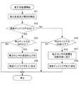
即ち、図10のステップS71において、風取得部91は、各風力センサ15−1乃至15−4から風の風力量をそれぞれ取得する。風取得部91は、取得した各風力量の情報を移動先算出部92に供給する。 That is, in step S71 of FIG. 10, the
ステップS72において、移動先算出部92は、ステップS71の処理で取得された各風力量のうち、表示部12の各端縁のそれぞれ対向する位置における各風力量の差分を算出する。
具体的には、表示部12の左右方向の各端縁のそれぞれ対向する位置に配置された風力センサ15−1,15−3の各風力量をそれぞれ、V1,V3とそれぞれ表記すると、移動先算出部92は、その差分として、V1−V3=Vxを算出する。同様に、表示部12の上下方向の各端縁のそれぞれ対向する位置に配置された風力センサ15−2,15−4の各風力量をそれぞれ、V2,V4とそれぞれ表記すると、移動先算出部92は、その差分として、V2−V3=Vyを算出する。In step S <b> 72, the movement
Specifically, when the wind power amounts of the wind sensors 15-1 and 15-3 disposed at the positions facing the respective edges in the left and right direction of the
ステップS73において、移動先算出部92は、ステップS72の処理で算出した各風力量の差分Vx,Vyに基づいてカーソルの移動先の位置を算出する。
具体的には本実施形態では、カーソルの移動先の位置は、カーソルの現在の位置に対する、左右方向の移動量と、上下方向の移動量とによって算出される。
即ち、風力量の差分Vxに基づき、表示部12の左右方向におけるカーソルの移動量が算出される。また、風力量の差分Vyに基づき、表示部12の上下方向におけるカーソルの移動量が算出される。In step S73, the movement
Specifically, in the present embodiment, the position to which the cursor is moved is calculated from the movement amount in the left-right direction and the movement amount in the vertical direction with respect to the current position of the cursor.
That is, the amount of movement of the cursor in the left-right direction of the
さらに以下、図11を参照して、カーソルの移動先の算出手法の一例について説明する。
図11は、風力量の差分とカーソルの移動量との関係を示す図である。
図11に示すように、カーソルの移動量は、風力量の差分を入力とする一次関数の出力として得られる。
例えば、移動先算出部92は、ステップS72の処理で算出した表示部12の左右(x軸)方向における差分Vxを入力パラメータとして図11の一次関数に代入すると、カーソルの左右方向の移動量として+60pixelを得ることができる。
同様に、移動先算出部92は、ステップS72の処理で算出した表示部12の上下(y軸)方向における差分Vyを入力パラメータとして図11の一次関数に代入すると、カーソルの上下方向の移動量として+100pixelを得ることができる。Further, an example of a method for calculating the cursor movement destination will be described below with reference to FIG.
FIG. 11 is a diagram illustrating the relationship between the difference in wind power and the amount of movement of the cursor.
As shown in FIG. 11, the amount of movement of the cursor is obtained as an output of a linear function that receives the difference in wind power.
For example, the movement
Similarly, the movement
ステップS74において、カーソル制御部93は、ステップS73の処理でカーソルの移動先として算出された位置にカーソルを移動させる(そのように表示部12の表示内容を変化させる)。
具体的には、表示部12において、ステップS73の処理で算出された左右方向の移動量の分だけ左右方向に、ステップS73の処理で算出された上下方向の移動量の分だけ上下方向に、それぞれカーソルが移動される。In step S74, the
Specifically, on the
図12は、表示部12におけるカーソルの移動の基準を示す図である。
図12に示す原点(X軸とY軸の交点)は、カーソルの現在位置を示している。そして、X軸の方向が左右方向とされており、特に、X軸の正方向が右方向とされ、X軸の負方向が左方向にされている。また、Y軸の方向が上下方向とされており、特に、Y軸の正方向が上方向とされ、Y軸の負方向が下方向にされている。
例えば、上述の例ではステップS73の処理で算出された左右方向(X軸方向)の移動量は+60pixelであることから、X軸の+方向、即ち右方向に60pixel分だけカーソルが移動される。また、ステップS73の処理で算出された上下方向(Y軸方向)の移動量は+100pixelであることから、Y軸の+方向、即ち上方向に100pixel分だけカーソルが移動される。FIG. 12 is a diagram illustrating a reference for moving the cursor on the
The origin (intersection of X axis and Y axis) shown in FIG. 12 indicates the current position of the cursor. The direction of the X axis is the left-right direction, and in particular, the positive direction of the X axis is the right direction, and the negative direction of the X axis is the left direction. The direction of the Y axis is the vertical direction, and in particular, the positive direction of the Y axis is the upward direction, and the negative direction of the Y axis is the downward direction.
For example, in the above example, the movement amount in the left-right direction (X-axis direction) calculated in the process of step S73 is +60 pixels, so the cursor is moved by 60 pixels in the + direction of the X-axis, that is, in the right direction. Further, since the movement amount in the vertical direction (Y-axis direction) calculated in the process of step S73 is +100 pixels, the cursor is moved by 100 pixels in the + direction of the Y-axis, that is, upward.
このようにして、ステップS74の処理によりカーソルが移動すると、移動先算出処理が終了する。即ち、図7のステップS16の処理が終了し、処理はステップS17のクリック検出処理に進む。
そこで以下、図13を参照して、クリック検出処理の詳細な流れについて説明する。
図13は、図7のユーザ入力対応処理のうち、ステップS17のクリック検出処理の流れを説明するフローチャートである。In this way, when the cursor moves in the process of step S74, the movement destination calculation process ends. That is, the process of step S16 in FIG. 7 ends, and the process proceeds to the click detection process of step S17.
Therefore, a detailed flow of the click detection process will be described below with reference to FIG.
FIG. 13 is a flowchart for explaining the flow of the click detection process in step S17 in the user input handling process of FIG.
即ち、図13のステップS91において、音検出部81は、音入力部13に入力された音の種別を検出する。 That is, in step S91 of FIG. 13, the
ステップS92において、音検出部81は、風切音が−3dB以上であるか否かを判定する。
ステップS91の処理で検出された音の種別が、風切音以外の種別であった場合や、風切音が−3dB未満であると判定された場合には、ステップS92においてNOであると判定されて、クリック検出処理が終了する。
即ち、音入力部13を通じて一定音量以上の風切音が取得できない場合には、音検出部81は、ユーザによるクリック入力が行われていないと判断して、クリック検出処理を終了させる。In step S92, the
If the type of sound detected in the process of step S91 is a type other than wind noise, or if it is determined that the wind noise is less than −3 dB, it is determined as NO in step S92. Then, the click detection process ends.
That is, when a wind noise of a certain volume or higher cannot be acquired through the
これに対して、風切音が−3dB以上であると判定された場合には、ステップS92においてYESであると判定されて、処理はステップS93に進む。この場合、音検出部81は、音の種別が風切音であり、その音量が−3dB以上であることを示す音検出情報を生成し、カーソル制御部93に供給する。 On the other hand, when it is determined that the wind noise is -3 dB or more, it is determined as YES in Step S92, and the process proceeds to Step S93. In this case, the
ステップS93において、カーソル制御部93は、−3dB以上の風切音を示す音検出情報が音検出部81から供給されたことをもって、ユーザによるクリック入力を検出する。
この処理が終了するとクリック検出処理が終了する。In step S <b> 93, the
When this process ends, the click detection process ends.
以上説明したように、本実施形態の位置入力装置10は、風検出部15と、移動先算出部92と、を備えている。
風検出部15は、複数の風力センサとして構成され、複数の風力センサが配置された複数位置における風に関する物理量として、風力を検出する。
移動先算出部92は、風検出部15により検出された各物理量(風力)に基づいて、表示部12におけるオブジェクト(カーソル)の移動先の位置を算出する。
このように、複数位置における風に関する各物理量に基づいてオブジェクトの移動先を算出することで、オブジェクトの移動先として適切な位置(ユーザが指示した位置)を算出することができる。このように、ユーザは、手指を触れることなく手軽にオブジェクト(カーソル)の位置を入力することが可能となる。As described above, the
The
The movement
Thus, by calculating the object movement destination based on the physical quantities related to the wind at a plurality of positions, it is possible to calculate an appropriate position (position designated by the user) as the object movement destination. Thus, the user can easily input the position of the object (cursor) without touching the fingers.
以上、本発明の第1実施形態に係る位置入力装置について説明した。
次に、本発明の第2実施形態に係る位置入力装置について説明する。The position input device according to the first embodiment of the present invention has been described above.
Next, a position input device according to a second embodiment of the present invention will be described.
[第2実施形態]
第1実施形態では、風検出部15は、4つの風力センサとして構成され、4つの風力センサの各々が配置された位置(4つの位置)における風に関する物理量として、風力量の検出を行っていた。
これに対し、第2実施形態で、図示はしないが、風力センサ15は、風力センサに換えて、感圧パッドにおける複数の感圧スイッチとして構成され、複数の感圧スイッチの各々が配置された位置(複数位置)における風に関する物理量として、風圧を検出する。[Second Embodiment]
In the first embodiment, the
On the other hand, although not shown in the second embodiment, the
即ち、本発明の第2実施形態に係る位置入力装置10の移動先算出処理を行うための機能的構成は、感圧パッドを構成する複数の感圧スイッチに基づく移動先算出処理を行う点を除くと、第1実施形態に係る位置入力装置10と基本的に同様である。
即ち、第1実施形態の位置入力装置10は、図6の各風検出部15−1乃至15−4により検出された各風の物理量の差分を算出し、算出した物理量の差分に基づいて、オブジェクトの一例としてのカーソルの移動先の位置を算出する。
これに対し、第2実施形態の位置入力装置10は、風検出部15を構成する、格子状に形成された各感圧スイッチの各々における風圧に基づいて、風の圧力分布を算出し、算出した圧力分布に基づきカーソルの移動先の位置を算出する。
なお、本発明の第2実施形態に係る撮像装置のハードウェアの構成は、第1実施形態に係る位置入力装置10の図1のハードウェアの構成と基本的に同様の構成で実現することができる。That is, the functional configuration for performing the movement destination calculation process of the
That is, the
On the other hand, the
Note that the hardware configuration of the imaging apparatus according to the second embodiment of the present invention can be realized by a configuration basically similar to the hardware configuration of FIG. 1 of the
ここで、風検出部15を構成する感圧スイッチは、公知の又は今後登場するであろう感圧導電材料からなるものであり、ブラックマスクと共通電極との間に配置されている。感圧スイッチは、表示部12の表示を妨げることがないように、上下左右の格子状に配置されるものとなっている。
さらに、感圧スイッチは、無圧状態、即ち、風が当たっていない状態で、ブラックマスクと共通電極とを電気的に絶縁状態に保つと共に、圧力がかかった状態、即ち、風が当たった状態で導電性になるために、ブラックマスクと共通電極とを短絡することができる。
従って、位置入力装置10は、感圧スイッチに対し風が当たった場合には、その感圧スイッチが配置されている箇所においての導通状態を確認することで、当該箇所で風力を受けたと判断することができる。これに対し、位置入力装置10は、感圧スイッチに対し風が当たっていない場合には、その感圧スイッチが配置されている箇所においての非導通状態を確認することで、風力を受けていないと判断することができる。Here, the pressure-sensitive switch constituting the
Further, the pressure sensitive switch is in a non-pressure state, that is, in a state where no wind is applied, and the black mask and the common electrode are electrically insulated and in a state where pressure is applied, ie, a state where the wind is applied. Therefore, the black mask and the common electrode can be short-circuited.
Therefore, when the wind is applied to the pressure sensitive switch, the
図14を参照して、このような第2実施形態に係る位置入力装置10が実行する移動先算出処理について説明する。
図14は、本発明の第2実施形態に係る位置入力装置10において行われる移動先算出処理の流れを説明するフローチャートである。
第1実施形態と同様に、図7のユーザ入力対応処理において、CPU51により、ステップS15の音入力処理の実行が終了すると、処理はステップS16に進み、移動先算出処理として次のような処理が実行される。With reference to FIG. 14, a destination calculation process executed by the
FIG. 14 is a flowchart illustrating the flow of a movement destination calculation process performed in the
As in the first embodiment, in the user input handling process of FIG. 7, when the
即ち、図14のステップS111において、風取得部91は、感圧パッドを構成する各感圧スイッチからなる風検出部15の風力の有無を示す風情報を取得する。風取得部91は、取得した風情報を移動先算出部92に供給する。 That is, in step S111 of FIG. 14, the
ステップS112において、移動先算出部92は、ステップS111の処理で取得された各風力の有無に基づいて、圧力分布を算出する。
具体的には、移動先算出部92は、格子状に配置された風検出部15として各感圧スイッチのうち、風力を受けたスイッチが配置された位置に、点をプロットした散布図を作成することによって、圧力分布を算出する。In step S112, the
Specifically, the
ステップS113において、移動先算出部92は、算出した圧力分布から最大圧力部分を検索し、その最大圧力部分の位置座標を、カーソルの移動先の位置として算出する。
具体的には、移動先算出部92は、ステップS112の処理で作成した圧力分布、即ち、各風力を受けた点をプロットした散布図のうち、プロット点が一番密集している部分を検索し、当該を部分を最大圧力部分として決定する。そして、移動先算出部92は、この決定した最大圧力部分の位置座標を算出する。In step S113, the movement
Specifically, the movement
ステップS114において、カーソル制御部93は、ステップS113において算出した位置座標にカーソルを移動させる(そのように表示部12に表示させる)。
この処理が終了すると、移動先算出処理が終了する。In step S114, the
When this process ends, the destination calculation process ends.
以上説明したように、第2実施形態の位置入力装置10は、風検出部15としての感圧パッドにおける各感圧スイッチにより検出された各物理量(風圧)の分布を演算し、当該分布に基づいてオブジェクトであるカーソルの移動先の位置を算出する。
これにより、表示部12の表示面上に無数に配置された各感圧スイッチに基づき、ユーザが指示するカーソルの移動先の位置座標を適切に算出することができる。このようにして、ユーザは、手指を触れることなく手軽にオブジェクトの移動先の位置を入力することが可能となる。As described above, the
Thereby, based on each pressure-sensitive switch arrange | positioned innumerably on the display surface of the
なお、本発明は、上述の実施形態に限定されるものではなく、本発明の目的を達成できる範囲での変形、改良等は本発明に含まれるものである。 In addition, this invention is not limited to the above-mentioned embodiment, The deformation | transformation in the range which can achieve the objective of this invention, improvement, etc. are included in this invention.
例えば、上述の第1実施形態では、風検出部15として構成される風力センサは、筺体11に4つ配置されているが、特にこれに限定されない。例えば、風力センサの数は4つ以上であればよいため、4つ以上の風力センサにより風検出部15が構成されていてもよい。 For example, in the first embodiment described above, four wind sensors configured as the
また、例えば、上述の実施形態では、カーソル制御部93は、移動先として算出された位置にカーソルを移動させる制御を実行しているが、制御の内容は特にこれに限られない。例えば、カーソル制御部93は、風検出部15により検出された風の物理量(風力量等)の強さに基づいてカーソルの移動速度の制御をさらに実行してもよい。 Further, for example, in the above-described embodiment, the
また、例えば、風検出部15としては、上述の第1実施形態では、シロッコファンにより検出する風力センサを採用し、上述の第2実施形態では、感圧パッドにおける各感圧スイッチを採用しているが、特にこれに限られない。例えば、熱電対や、ピトー管等、風に関する物理量を検出できる任意のセンサを、風検出部15として採用することができる。 In addition, for example, as the
また、例えば、上述の実施形態では、音取得部72は、風切音が−3dB以上であるか否かに応じてクリック入力を検出しているが特にこれに限られない。例えば、風の風力量、又は、風の音量の変化を複数回検出したり、或いは、吃音等の別の音を検出することにより、クリック入力を検出するようにしてもよい。 Further, for example, in the above-described embodiment, the sound acquisition unit 72 detects a click input according to whether or not the wind noise is −3 dB or more, but is not limited thereto. For example, the click input may be detected by detecting a change in the amount of wind or the volume of the wind a plurality of times, or by detecting another sound such as a roar.
また、例えば、上述の実施形態では、風検出部15の検出結果は、カーソルの移動先の位置の演算や、クリック入力の検出に用いられていたが、その用途は特にこれに限らない。例えば、風力センサとして構成される風検出部15−1乃至15−4により検出された風力量に基づいて、表示部12に表示されている映像が揺れたり、風鈴が鳴ったり、風車が回ったりするようにしてもよい。 Further, for example, in the above-described embodiment, the detection result of the
また、例えば、風検出部15として、上述の第1実施形態では風力センサを採用し、第2実施形態では感圧パッドを構成する複数の感圧スイッチを採用していたが、風検出部15として採用するセンサ等は特に1種類である必要はなく、複数種類でもよい。例えば、第1実施形態の風力センサと、第2実施形態の感圧パッドを構成する複数の感圧スイッチとを組み合わせて、風検出部15としてもよい。これにより、位置入力の精度をさらに一段と高めることができる。 Further, for example, as the
また、上述の実施形態では、オブジェクトの選択によりオブジェクトが移動する場合について説明したが、本発明はこれに限定されない。オブジェクトの選択により、オブジェクトが移動する代わりに、オブジェクトに関連付けられたアプリケーションの起動、終了等の操作が行われるように構成してもよい。この場合は、カーソル制御部93が、風取得部91が取得した各風情報に基づいてオブジェクトに関連付けられたアプリケーションの起動、終了等の操作を行うようにすればよい。 In the above-described embodiment, the case where the object is moved by the selection of the object has been described, but the present invention is not limited to this. Instead of moving the object by the selection of the object, operations such as activation and termination of an application associated with the object may be performed. In this case, the
また例えば、上述した実施形態では、本発明が適用される位置入力装置は、フォトフレームとして構成される例として説明した。
しかしながら、本発明は、特にこれに限定されず、入力機能を有する電子機器一般に適用することができ、例えば、本発明は、携帯電話、パーソナルコンピュータ、携帯型ナビゲーション装置、ポータブルゲーム機等に幅広く適用可能である。For example, in the above-described embodiment, the position input device to which the present invention is applied has been described as an example configured as a photo frame.
However, the present invention is not particularly limited to this, and can be applied to general electronic devices having an input function. For example, the present invention is widely applied to mobile phones, personal computers, portable navigation devices, portable game machines, and the like. Is possible.
上述した一連の処理は、ハードウェアにより実行させることもできるし、ソフトウェアにより実行させることもできる。 The series of processes described above can be executed by hardware or can be executed by software.
一連の処理をソフトウェアにより実行させる場合には、そのソフトウェアを構成するプログラムが、コンピュータ等にネットワークや記録媒体からインストールされる。コンピュータは、専用のハードウェアに組み込まれているコンピュータであってもよい。また、コンピュータは、各種のプログラムをインストールすることで、各種の機能を実行することが可能なコンピュータ、例えば汎用のパーソナルコンピュータであってもよい。 When a series of processing is executed by software, a program constituting the software is installed on a computer or the like from a network or a recording medium. The computer may be a computer incorporated in dedicated hardware. The computer may be a computer capable of executing various functions by installing various programs, for example, a general-purpose personal computer.
このようなプログラムを含む記録媒体は、ユーザにプログラムを提供するために装置本体とは別に配布されるリムーバブルメディア31により構成されるだけでなく、装置本体に予め組み込まれた状態でユーザに提供される記録媒体等で構成される。リムーバブルメディア71は、例えば、磁気ディスク(フロッピディスクを含む)、光ディスク、又は光磁気ディスク等により構成される。光ディスクは、例えば、CD−ROM(Compact Disk−Read Only Memory),DVD(Digital Versatile Disk)等により構成される。光磁気ディスクは、MD(Mini−Disk)等により構成される。また、装置本体に予め組み込まれた状態でユーザに提供される記録媒体は、例えば、プログラムが記録されているROM52やハードディスク等で構成される。 A recording medium including such a program is provided not only to the removable medium 31 distributed separately from the apparatus main body in order to provide the program to the user, but also to the user in a state of being incorporated in the apparatus main body in advance. Recording medium. The
なお、本明細書において、記録媒体に記録されるプログラムを記述するステップは、その順序に沿って時系列的に行われる処理はもちろん、必ずしも時系列的に処理されなくとも、並列的或いは個別に実行される処理をも含むものである。 In the present specification, the step of describing the program recorded on the recording medium is not limited to the processing performed in time series along the order, but is not necessarily performed in time series, either in parallel or individually. The process to be executed is also included.
10・・・位置入力装置、11・・・筺体、11a・・・基台、11b・・・上部カバー、12・・・表示部、13・・・音入力部、14−1,14−2,14−3,14−4・・・孔、15−1,15−2,15−3,15−4・・・風検出部、16・・・センサ筺体、17・・・ファン、18・・・フォトカプラ、19・・・入口孔部、20・・・出口孔部、51・・・CPU、52・・・ROM、53・・・RAM、56・・・操作部、57・・・音出力部、58・・・通信部、59・・・ドライブ、71・・・リムーバブルメディア、81・・・音取得部、82・・・感度設定部、91・・・風取得部、92・・・移動先算出部、93・・・カーソル制御部 DESCRIPTION OF
Claims (10)
Translated fromJapanese前記風検出手段により検出された各物理量に基づいて、前記ユーザにより移動が指示された前記オブジェクトの移動先の位置を算出する移動先算出手段と、
を備える位置入力装置。Wind detection means for detecting physical quantities related to the wind at a plurality of positions for the wind generated by the user to input an instruction to move the object on the display unit;
Based on each physical quantity detected by the wind detection means, a movement destination calculation means for calculating the position of the movement destination of the object instructed to move by the user;
A position input device comprising:
前記移動先算出手段は、前記風検出手段により検出された、前記対向する位置における各物理量の差分を演算し、前記差分に基づいてオブジェクトの移動先の位置を算出する、
請求項1に記載の位置入力装置。The wind detection means detects physical quantities related to wind at positions facing each of the edges of the display unit,
The movement destination calculation means calculates a difference between the physical quantities detected at the opposing positions detected by the wind detection means, and calculates the position of the movement destination of the object based on the difference.
The position input device according to claim 1.
請求項1に記載の位置入力装置。The movement destination calculation means obtains a distribution of each physical quantity detected by the wind detection means, and calculates the position of the movement destination of the object based on the distribution.
The position input device according to claim 1.
請求項1乃至3の何れか1項に記載の位置入力装置。The display unit further includes cursor control means for executing control to move the cursor to the position of the movement destination calculated by the movement destination calculation means.
The position input device according to any one of claims 1 to 3.
請求項4に記載の位置入力装置。The position input device according to claim 4, wherein the cursor control unit further controls the movement speed of the cursor based on the strength of the physical quantity of the wind acquired by the wind detection unit.
前記音検出手段によって検出された第1の音の音量に応じて、前記風検出手段の検出の感度を設定する感度設定手段と、
をさらに備える請求項4又は5に記載の位置入力装置。Sound detection means for detecting sound;
Sensitivity setting means for setting the detection sensitivity of the wind detection means according to the volume of the first sound detected by the sound detection means;
The position input device according to claim 4 or 5, further comprising:
請求項6に記載の位置入力装置。The cursor control means further executes control for determining that a click input for selecting an object indicated by the cursor is made when a second sound different from the first sound is detected by the sound detection means. To
The position input device according to claim 6.
請求項7に記載の位置入力装置。The first sound and the second sound are sounds having different frequencies,
The position input device according to claim 7.
表示部におけるオブジェクトの移動の指示を入力するためにユーザにより発生された風について、複数位置における前記風に関する物理量をそれぞれ検出する風検出ステップと、
前記風検出ステップにより検出された各物理量に基づいて、前記ユーザにより移動が指示された前記オブジェクトの移動先の位置を算出する移動先算出ステップと、
を含む位置入力方法。A position input method of a position input device that executes control for calculating a position of a movement destination of an object on a display unit,
A wind detection step of detecting physical quantities related to the wind at a plurality of positions, respectively, with respect to the wind generated by the user in order to input an instruction to move the object on the display unit;
A destination calculation step of calculating a position of the destination of the object instructed to move by the user based on each physical quantity detected by the wind detection step;
Position input method including
表示部におけるオブジェクトの移動の指示を入力するためにユーザにより発生された風について、複数位置における前記風に関する物理量をそれぞれ検出する風検出機能と、
前記風検出機能により検出された各物理量に基づいて、前記ユーザにより移動が指示された前記オブジェクトの移動先の位置を算出する移動先算出機能と、
を実現させるプログラム。A computer that controls a position input device including a destination calculation unit that executes control for calculating a position of a destination of an object on the display unit,
A wind detection function for detecting physical quantities related to the wind at a plurality of positions, respectively, with respect to the wind generated by the user in order to input an instruction to move the object on the display unit;
Based on each physical quantity detected by the wind detection function, a destination calculation function for calculating a destination position of the object instructed to move by the user;
A program that realizes
Priority Applications (1)
| Application Number | Priority Date | Filing Date | Title |
|---|---|---|---|
| JP2010245586AJP2012098892A (en) | 2010-11-01 | 2010-11-01 | Position input device, position input method and program |
Applications Claiming Priority (1)
| Application Number | Priority Date | Filing Date | Title |
|---|---|---|---|
| JP2010245586AJP2012098892A (en) | 2010-11-01 | 2010-11-01 | Position input device, position input method and program |
Publications (2)
| Publication Number | Publication Date |
|---|---|
| JP2012098892Atrue JP2012098892A (en) | 2012-05-24 |
| JP2012098892A5 JP2012098892A5 (en) | 2013-12-05 |
Family
ID=46390729
Family Applications (1)
| Application Number | Title | Priority Date | Filing Date |
|---|---|---|---|
| JP2010245586APendingJP2012098892A (en) | 2010-11-01 | 2010-11-01 | Position input device, position input method and program |
Country Status (1)
| Country | Link |
|---|---|
| JP (1) | JP2012098892A (en) |
Citations (7)
| Publication number | Priority date | Publication date | Assignee | Title |
|---|---|---|---|---|
| JPH06342365A (en)* | 1990-12-26 | 1994-12-13 | Internatl Business Mach Corp <Ibm> | Method and apparatus for linear sound control |
| JP2000148379A (en)* | 1998-11-12 | 2000-05-26 | Murata Mfg Co Ltd | Computer pointing device |
| JP2002366275A (en)* | 2001-06-08 | 2002-12-20 | Victor Co Of Japan Ltd | Electronic voting terminal |
| JP2004177992A (en)* | 2002-11-22 | 2004-06-24 | Panasonic Mobile Communications Co Ltd | Portable terminal with wind pressure sensor and program executable by portable terminal with wind pressure sensor |
| JP2004280301A (en)* | 2003-03-13 | 2004-10-07 | Yoshitaka Fukumoto | Pointing device |
| WO2009120856A2 (en)* | 2008-03-26 | 2009-10-01 | Inputive Corporation | Method and system for interfacing with an electronic device via respiratory and/or tactual input |
| JP2009230182A (en)* | 2008-03-19 | 2009-10-08 | Equos Research Co Ltd | Information input device |
- 2010
- 2010-11-01JPJP2010245586Apatent/JP2012098892A/enactivePending
Patent Citations (8)
| Publication number | Priority date | Publication date | Assignee | Title |
|---|---|---|---|---|
| JPH06342365A (en)* | 1990-12-26 | 1994-12-13 | Internatl Business Mach Corp <Ibm> | Method and apparatus for linear sound control |
| JP2000148379A (en)* | 1998-11-12 | 2000-05-26 | Murata Mfg Co Ltd | Computer pointing device |
| JP2002366275A (en)* | 2001-06-08 | 2002-12-20 | Victor Co Of Japan Ltd | Electronic voting terminal |
| JP2004177992A (en)* | 2002-11-22 | 2004-06-24 | Panasonic Mobile Communications Co Ltd | Portable terminal with wind pressure sensor and program executable by portable terminal with wind pressure sensor |
| JP2004280301A (en)* | 2003-03-13 | 2004-10-07 | Yoshitaka Fukumoto | Pointing device |
| JP2009230182A (en)* | 2008-03-19 | 2009-10-08 | Equos Research Co Ltd | Information input device |
| WO2009120856A2 (en)* | 2008-03-26 | 2009-10-01 | Inputive Corporation | Method and system for interfacing with an electronic device via respiratory and/or tactual input |
| JP2011520167A (en)* | 2008-03-26 | 2011-07-14 | ピエール・ボナ | Method and system for interfacing with electronic devices via respiratory input and / or tactile input |
Similar Documents
| Publication | Publication Date | Title |
|---|---|---|
| JP5423686B2 (en) | Computer program, input device and input method | |
| EP2332023B1 (en) | Two-thumb qwerty keyboard | |
| CN104914987B (en) | Systems and methods for a haptically-enabled projected user interface | |
| KR102051418B1 (en) | User interface controlling device and method for selecting object in image and image input device | |
| EP3114556B1 (en) | Proximity sensor-based interactions | |
| JP5958215B2 (en) | Information terminal device, touch coordinate determination method, and touch coordinate determination program | |
| EP3023865B1 (en) | Portable terminal having display and method for operating same | |
| US20110018795A1 (en) | Method and apparatus for controlling electronic device using user interaction | |
| JP2012502393A (en) | Portable electronic device with relative gesture recognition mode | |
| TW200813795A (en) | Method, apparatus, and computer program product for entry of data or commands based on tap detection | |
| KR20150019352A (en) | Method and apparatus for grip recognition in electronic device | |
| KR20140060818A (en) | Remote controller and display apparatus, control method thereof | |
| JP2010102474A (en) | Information display device, personal digital assistant, display control method, and display control program | |
| WO2019105376A1 (en) | Gesture recognition method, terminal and storage medium | |
| US20150026638A1 (en) | Apparatus and method of controlling external input device, and computer-readable recording medium | |
| CN103164156A (en) | Touch input method and apparatus of portable terminal | |
| US20150002417A1 (en) | Method of processing user input and apparatus using the same | |
| KR101339985B1 (en) | Display apparatus, remote controlling apparatus and control method thereof | |
| CN108733275A (en) | A kind of object displaying method and terminal | |
| KR20160047775A (en) | Method of user input of portable device using virtual input area | |
| WO2018094558A1 (en) | Floating touch control sensing method, floating touch control sensing system and floating touch control electronic device | |
| JP2013058037A (en) | Item selection device, item selection method, and program | |
| CN101546231B (en) | Method and device for multi-object orientation touch selection | |
| JP2012098892A (en) | Position input device, position input method and program | |
| JP6233040B2 (en) | Input device, display control method, program, and integrated circuit device |
Legal Events
| Date | Code | Title | Description |
|---|---|---|---|
| A521 | Request for written amendment filed | Free format text:JAPANESE INTERMEDIATE CODE: A523 Effective date:20131017 | |
| A621 | Written request for application examination | Free format text:JAPANESE INTERMEDIATE CODE: A621 Effective date:20131017 | |
| A977 | Report on retrieval | Free format text:JAPANESE INTERMEDIATE CODE: A971007 Effective date:20140528 | |
| A131 | Notification of reasons for refusal | Free format text:JAPANESE INTERMEDIATE CODE: A131 Effective date:20140708 | |
| A02 | Decision of refusal | Free format text:JAPANESE INTERMEDIATE CODE: A02 Effective date:20141104 |