JP2012095152A - Portable electronic device - Google Patents
Portable electronic deviceDownload PDFInfo
- Publication number
- JP2012095152A JP2012095152AJP2010241493AJP2010241493AJP2012095152AJP 2012095152 AJP2012095152 AJP 2012095152AJP 2010241493 AJP2010241493 AJP 2010241493AJP 2010241493 AJP2010241493 AJP 2010241493AJP 2012095152 AJP2012095152 AJP 2012095152A
- Authority
- JP
- Japan
- Prior art keywords
- housing
- module
- recess
- electronic device
- metal plate
- Prior art date
- Legal status (The legal status is an assumption and is not a legal conclusion. Google has not performed a legal analysis and makes no representation as to the accuracy of the status listed.)
- Pending
Links
- 229920005989resinPolymers0.000claimsabstractdescription43
- 239000011347resinSubstances0.000claimsabstractdescription43
- 239000002184metalSubstances0.000claimsabstractdescription32
- 239000000853adhesiveSubstances0.000claimsdescription13
- 230000001070adhesive effectEffects0.000claimsdescription13
- 239000000758substrateSubstances0.000claimsdescription5
- 230000002093peripheral effectEffects0.000claimsdescription2
- 238000000465mouldingMethods0.000abstractdescription6
- 238000012856packingMethods0.000description9
- 230000001413cellular effectEffects0.000description5
- 230000000149penetrating effectEffects0.000description4
- 239000000463materialSubstances0.000description3
- 229910001220stainless steelInorganic materials0.000description2
- 239000010935stainless steelSubstances0.000description2
- NIXOWILDQLNWCW-UHFFFAOYSA-Nacrylic acid groupChemical groupC(C=C)(=O)ONIXOWILDQLNWCW-UHFFFAOYSA-N0.000description1
- 238000004891communicationMethods0.000description1
- 239000003822epoxy resinSubstances0.000description1
- 230000001771impaired effectEffects0.000description1
- 230000010365information processingEffects0.000description1
- 239000004973liquid crystal related substanceSubstances0.000description1
- 238000004519manufacturing processMethods0.000description1
- 238000012986modificationMethods0.000description1
- 230000004048modificationEffects0.000description1
- 229920000647polyepoxidePolymers0.000description1
- 230000002265preventionEffects0.000description1
- 238000005549size reductionMethods0.000description1
- 230000005236sound signalEffects0.000description1
- 239000012780transparent materialSubstances0.000description1
- 238000004078waterproofingMethods0.000description1
Images


Classifications
- H—ELECTRICITY
- H04—ELECTRIC COMMUNICATION TECHNIQUE
- H04M—TELEPHONIC COMMUNICATION
- H04M1/00—Substation equipment, e.g. for use by subscribers
- H04M1/02—Constructional features of telephone sets
- H04M1/0202—Portable telephone sets, e.g. cordless phones, mobile phones or bar type handsets
- H04M1/0206—Portable telephones comprising a plurality of mechanically joined movable body parts, e.g. hinged housings
- H04M1/0208—Portable telephones comprising a plurality of mechanically joined movable body parts, e.g. hinged housings characterized by the relative motions of the body parts
- H04M1/0214—Foldable telephones, i.e. with body parts pivoting to an open position around an axis parallel to the plane they define in closed position
- H04M1/0216—Foldable in one direction, i.e. using a one degree of freedom hinge
- H—ELECTRICITY
- H04—ELECTRIC COMMUNICATION TECHNIQUE
- H04M—TELEPHONIC COMMUNICATION
- H04M1/00—Substation equipment, e.g. for use by subscribers
- H04M1/02—Constructional features of telephone sets
- H04M1/0202—Portable telephone sets, e.g. cordless phones, mobile phones or bar type handsets
- H04M1/0206—Portable telephones comprising a plurality of mechanically joined movable body parts, e.g. hinged housings
- H04M1/0208—Portable telephones comprising a plurality of mechanically joined movable body parts, e.g. hinged housings characterized by the relative motions of the body parts
- H04M1/021—Portable telephones comprising a plurality of mechanically joined movable body parts, e.g. hinged housings characterized by the relative motions of the body parts using combined folding and rotation motions
- H04M1/0212—Portable telephones comprising a plurality of mechanically joined movable body parts, e.g. hinged housings characterized by the relative motions of the body parts using combined folding and rotation motions with a two degrees of freedom mechanism, i.e. folding around a first axis and rotating around a second axis perpendicular to the first
- H—ELECTRICITY
- H04—ELECTRIC COMMUNICATION TECHNIQUE
- H04M—TELEPHONIC COMMUNICATION
- H04M1/00—Substation equipment, e.g. for use by subscribers
- H04M1/02—Constructional features of telephone sets
- H04M1/18—Telephone sets specially adapted for use in ships, mines, or other places exposed to adverse environment
Landscapes
- Engineering & Computer Science (AREA)
- Signal Processing (AREA)
- Telephone Set Structure (AREA)
- Casings For Electric Apparatus (AREA)
Abstract
Description
Translated fromJapanese本発明は、携帯電子機器に関し、更に詳しくは、防水機能を備える携帯電子機器に関する。 The present invention relates to a portable electronic device, and more particularly to a portable electronic device having a waterproof function.
携帯電子機器は、その携帯性から様々な環境で使用される。種々の使用環境に対応するため、携帯電子機器は、防水機能を備えることが望まれる。例えば、下記特許文献には、防水機能を備える携帯電子機器が開示されている。 Portable electronic devices are used in various environments due to their portability. In order to cope with various usage environments, it is desired that the portable electronic device has a waterproof function. For example, the following patent document discloses a portable electronic device having a waterproof function.
上記特許文献1に記載の携帯電子機器は、構成部品同士の隙間を、防水パッキンにより塞いでいる。しかしながら、この場合、防水パッキンを嵌め込むための溝の寸法等、構成部品の寸法に高い精度が求められる。また、ねじやフック等の部材を用いて、構成部品同士を締め付けて、防水パッキンを圧縮する必要もある。この結果、コストが高くなるとともに、歩留まりが悪くなるおそれがある。また、構造が複雑になることから、携帯電子機器を小型化、薄型化することが難しく、近年の携帯電子機器の小型化、薄型化の趨勢に反してしまう。 In the portable electronic device described in Patent Document 1, a gap between components is closed with a waterproof packing. However, in this case, high accuracy is required for the dimensions of the component parts, such as the dimensions of the grooves for fitting the waterproof packing. Further, it is necessary to compress the waterproof packing by tightening the components using members such as screws and hooks. As a result, the cost increases and the yield may deteriorate. In addition, since the structure is complicated, it is difficult to reduce the size and thickness of portable electronic devices, which is contrary to the recent trend of reducing the size and thickness of portable electronic devices.
上記特許文献2に記載の携帯電子機器は、構成部品同士の隙間を、防止パッキンではなく、両面テープによって塞ぐことにより、防水構造を簡素にしている。しかしながら、この携帯電子機器は、筐体の内部に回路基板が収納され、さらに、この回路基板上に表示モジュールが配置される構造となっている。この回路基板には、多くの電子部品が実装されていることから、表示モジュールは、電子部品との干渉を避けるように固定される。これにより、表示モジュールの固定が十分ではなく、不安定な状態となってしまう。そのため、ユーザが誤って落とすなどして、この携帯電子機器に衝撃が加わった場合、表示モジュールが筐体から容易に外れてしまい、ひいては、表示モジュールが破損するおそれがある。 In the portable electronic device described in Patent Document 2, the waterproof structure is simplified by closing the gap between the component parts with a double-sided tape instead of the prevention packing. However, this portable electronic device has a structure in which a circuit board is housed in a housing, and a display module is disposed on the circuit board. Since many electronic components are mounted on this circuit board, the display module is fixed so as to avoid interference with the electronic components. As a result, the display module is not sufficiently fixed and becomes unstable. Therefore, when an impact is applied to the portable electronic device, for example, when the user accidentally drops the display module, the display module is easily detached from the casing, and as a result, the display module may be damaged.
本発明は、上述の事情の下になされたもので、簡素な防水構造を有し、衝撃に強い携帯電子機器を提供することを目的とする。 The present invention has been made under the above circumstances, and an object thereof is to provide a portable electronic device having a simple waterproof structure and strong against impact.
上述の目的を達成するために、本発明に係る携帯電子機器は、
第1筐体と、
前記第1筐体上の一の面側に固定され、電子部品を備える電子モジュールと、
防水性の接着部材を介して、前記第1筐体に水密に取り付けられることにより、前記電子モジュールを覆う第1カバーと、
前記第1筐体上の他の面側に固定され、回路基板を含む基板モジュールと、
防水性の接着部材を介して、前記第1筐体に水密に取り付けられることにより、前記基板モジュールを覆う第2カバーと、
を有することを特徴とする。In order to achieve the above object, a portable electronic device according to the present invention includes:
A first housing;
An electronic module fixed to one surface on the first housing and provided with an electronic component;
A first cover that covers the electronic module by being watertightly attached to the first housing via a waterproof adhesive member;
A board module fixed to the other surface of the first housing and including a circuit board;
A second cover that covers the substrate module by being watertightly attached to the first housing via a waterproof adhesive member;
It is characterized by having.
本発明によれば、接着部材により防水性を確保するとともに、例えば、表示モジュールなどの電子モジュールは、第1筐体に直接固定されている。このため、簡素な防水構造のまま、耐衝撃性を向上させることができる。 According to the present invention, waterproofness is ensured by the adhesive member, and for example, an electronic module such as a display module is directly fixed to the first housing. For this reason, impact resistance can be improved with a simple waterproof structure.
以下、本発明の実施形態に係る携帯電話機10について、図面を参照しつつ説明する。なお、理解を容易にするため、X軸を携帯電話機10の側面方向、Y軸を携帯電話機10の鉛直方向、Z軸を携帯電話機10の正面方向とするXYZ座標を設定し、適宜参照する。 Hereinafter, a
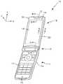
携帯電話機10は、携帯時等には閉じた状態とし、通話時等には、図1に示すように、展開した状態とすることが可能な折り畳み式携帯電話機である。携帯電話機10は、操作ユニット11と、表示ユニット12と、ヒンジユニット13と、を有しており、表示ユニット12は、ヒンジユニット13を介して、操作ユニット11に回動可能に接続されている。 The
操作ユニット11は、直方体板状の操作筐体11aを有しており、この操作筐体11aには、テンキー、方向キー/決定キー、及びファンクションキー等からなる操作キー14が配設されている。ユーザによる情報の入力は、この操作キー14を通じて行われる。 The
操作筐体11aには、操作キー14からの入力を検知するための電子モジュールや、ユーザの音声を音声信号に変換して出力するためのマイクモジュール等が、収納されている。マイクモジュールは、操作筐体11aに形成された孔16近傍に配置されている。 The
表示ユニット12の表面には、表示画面15が配設されている。この表示画面15は、画像、図形、文字、記号などの情報を、ユーザに表示する。表示画面15は、例えば、液晶ディスプレイから構成される。ユーザは、この表示画面15を、表示ユニット11の+Z側から視認することができる。 A
また、表示ユニット12は、図2に示すように、表示筐体20と、フロントパネル30と、両面テープ31,34と、表示モジュール32と、回路基板33と、リアパネル35と、レシーバモジュール36と、カメラモジュール37と、を有している。 2, the
表示筐体20は、略直方体状の部材であり、図3に示すように、金属板21と、金属板21上に形成された樹脂部22と、を有する。金属板21は、例えば、ステンレス鋼からなる。金属板21の縁には、全周に渡って、湾曲部21aが形成されている。この湾曲部21aによって、表示筐体20の強度が確保される。金属板21は、例えば、ステンレス鋼の板をプレス成形することにより形成される。 The
樹脂部22は、金属板21の湾曲部21aを覆って、略枠形状に形成されている。樹脂部22は、例えば、インサート成形により形成される。樹脂部22の正面側(+Z側)の面には、フロントパネル30を貼り付けるための貼付面22aが形成されている。この貼付面22aは、後述する凹部23の縁に沿って、形成されている。 The
同様に、樹脂部22の背面側(−Z側)の面には、リアパネル35を貼り付けるための貼付面22bが形成されている。この貼付面22bは、後述する凹部24の縁に沿って、形成されている。また、樹脂部22は、金属板21の正面側(+Z側)に形成された樹脂量と背面側(−Z側)に形成された樹脂量とがそれぞれほぼ均等となるように、金属板21上に形成されている。 Similarly, a
表示筐体20には、金属板21の正面側の表面と、樹脂部22の表面と、によって規定される凹部23が形成されている。この凹部23には、表示モジュール32が収納される。 The
同様に、表示筐体20には、金属板21の背面側の表面と、樹脂部22の表面と、によって規定される凹部24が形成されている。この凹部24には、回路基板33が収納される。 Similarly, the
表示筐体20の上方には、レシーバモジュール36やカメラモジュール37を収納するためのモジュール収納部25が形成されている。モジュール収納部25は、Z方向に貫通する孔26によって、表示筐体20の正面側(+Z側)に通じている。孔26の形状は、任意である。本実施形態においては、孔26は、長円形状に形成されている。また、モジュール収納部25の上方を覆うように、樹脂部22には庇部27が形成されている。この庇部27の背面側(−Z側)の面は、上述した貼付面22bを構成する。 A
表示筐体20の下方には、後述するヒンジユニット13が嵌め込まれる凹部28が形成されている。そして、この凹部28の上方には、複数のナット29が埋設されている。ナット29の数は、任意である。本実施形態においては、X方向に沿って4つ埋設されている。 A
フロントパネル30は、図4に示すように、表示モジュール32を保護する。フロントパネル30は、アクリル製の透明な素材からなる。フロントパネル30は、両面テープ31を介して、樹脂部22の貼付面22aに固定される。 The
両面テープ31は、防水性の素材からなる。また、両面テープ31は、枠形状に形成されている。両面テープ31は、樹脂部22の貼付面22aに貼り付けられる。 The double-
表示モジュール32は、表示画面15を有する表示素子と、この表示素子が実装される基板などから構成されている。表示モジュール32は、表示筐体20の凹部23に収納され、金属板21上に直接固定される。また、表示モジュール32は、図示しないフレキシブル配線基板等によって、回路基板33に電気的に接続されている。 The
回路基板33は、例えば、エポキシ樹脂からなる。この回路基板33には、回路パターンが形成され、図示しない電子部品等が実装されている。回路基板33は、表示筐体20の凹部24に収納され、金属板21上に直接固定される。 The
リアパネル35は、回路基板33やレシーバモジュール36、カメラモジュール37等を保護し、略板状に形成されている。リアパネル35は、例えば、樹脂からなる。リアパネル35は、両面テープ34を介して、樹脂部22の貼付面22bに固定される。 The
両面テープ34は、両面テープ31と同様に、防水性の素材からなる。また、両面テープ34は、枠形状に形成されている。両面テープ34は、樹脂部22の貼付面22bに貼り付けられる。 Similar to the double-
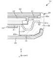
レシーバモジュール36は、音声信号に基づく音声を出力する。レシーバモジュール36は、図5(A)に示すように、庇部27の下方から挿入されて、モジュール収納部25に収納される。そして、レシーバモジュール36は、レシーバモジュール押さえ19によって固定され、孔26近傍に配置される。また、孔26の正面側には、カバー17が取り付けられている。カバー17は、レシーバモジュール36を防水、防塵するための部材で、例えば、樹脂からなる。 The
カメラモジュール37は、CMOS等の撮像素子から構成され、ユーザ等を撮像する。カメラモジュール37は、図1に示す表示筐体20の孔18近傍に配置される。 The
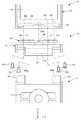
ヒンジユニット13は、図6に示すように、ヒンジユニット本体40と、ヒンジユニット本体40の+Y側に取り付けられた回転プレート41と、を有する。 As shown in FIG. 6, the
回転プレート41は、ヒンジユニット本体40に対して、Y軸回りに回動可能に取り付けられている。この回転プレート41には、Y方向に貫通する孔43が、X方向に沿って複数形成されている。この孔43は、例えば、円形に形成されている。また、孔43の数は、表示筐体20の下方に埋設されたナット29の数と等しく、本実施形態では、孔43は、4つ形成されている。回転プレート41の中央には、防水性のコネクタ44が形成されている。このコネクタ44は、ヒンジユニット13が表示ユニット12に接続された場合に、表示筐体20の凹部28内に形成されたコネクタ28aに接続される。 The
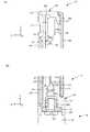
ヒンジユニット13は、締結ねじ50によって、表示ユニット12に取り付けられている。詳しくは、締結ねじ50を、回転プレート41の孔43及び表示筐体20のナット29に、+Y方向にねじ込むことによって、回転プレート41は、表示筐体20に取り付けられる。これにより、図5(B)に示すように、ヒンジユニット13と表示ユニット12とが接続される。また、同時に、ヒンジユニット13の回転プレート41に形成されたコネクタ44と、表示筐体20の凹部28に形成されたコネクタ28aと、が接続される。なお、ねじ込まれた締結ねじ50のねじ頭は、凹部28内に収納される。 The
ヒンジユニット本体40の−Y側には、図6に示すように、ヒンジ筒42が形成されている。このヒンジ筒42には、X軸方向に貫通する孔42aが形成されている。 As shown in FIG. 6, a
また、操作ユニット11の+Y側の端部には、一対のヒンジ筒45が形成されている。このヒンジ筒45には、X軸方向に貫通する孔45aが形成されている。この孔45aと、ヒンジユニット本体40のヒンジ筒42に形成された孔42aとに、ヒンジ軸が挿入される。このヒンジ軸の挿入により、操作ユニット11とヒンジユニット13とが接続される。 A pair of
ヒンジユニット本体40の内部には、図示しないケーブルが配置されている。ケーブルには、例えば、防水チューブが被覆された同軸ケーブルや、防水性のフレキシブルケーブル等が用いられる。ケーブルの一端は、回転プレート41のコネクタ44に接続されている。そして、ケーブルの他端は、ヒンジ筒42から引き出され、操作ユニット11の電子ユニット等に接続されている。 A cable (not shown) is arranged inside the hinge unit
上述の携帯電話機10は、以下のように組み立てられる。図4を参照するとわかるように、先ず、表示筐体20の凹部23に、表示モジュール32を固定する。同様に、表示筐体20の凹部24に、ねじ等によって、回路基板33を固定する。そして、図示しないフレキシブル配線基板を、表示モジュール32と回路基板33とに接続する。これにより、表示モジュール32と回路基板33とは、電気的に接続される。 The
次に、図5(A)を参照するとわかるように、樹脂部22の庇部27の下方からモジュール収納部25内に、レシーバモジュール36を挿入する。そして、レシーバモジュール36の下端を、レシーバモジュール押さえ19によって固定する。同様に、図示しないカメラモジュール37も、樹脂部22の庇部27の下方からモジュール収納部25内に挿入し、固定する。 Next, as can be seen with reference to FIG. 5A, the
次に、図4及び図5を参照するとわかるように、表示筐体20の樹脂部22の貼付面22aに、両面テープ31を貼り付ける。そして、この両面テープ31を介して、フロントパネル30を貼付面22aに固定する。同様に、樹脂部22の貼付面22bに、両面テープ34を貼り付ける。そして、この両面テープ34を介して、フロントパネル30を貼付面22bに固定する。これにより、表示モジュール32や回路基板33等は、表示筐体20内に水密に保護される。以上により、表示ユニット12の組み立てが完了する。 Next, as can be seen with reference to FIGS. 4 and 5, the double-
次に、図6を参照するとわかるように、締結ねじ50を、ヒンジユニット13の回転プレート41の孔43を介して、表示筐体20のナット29にそれぞれ挿入する。このとき、回転プレート41を、ヒンジユニット本体40に対して、Y軸回りに90°回動させておく。そして、ドライバー等の工具を用いて、締結ねじ50をねじ込む。これにより、ヒンジユニット13は、表示ユニット12に接続される。 Next, as can be seen with reference to FIG. 6, the fastening screws 50 are respectively inserted into the
次に、ヒンジユニット13のヒンジユニット本体40のヒンジ筒42と、操作ユニット11のヒンジ筒45とに、ヒンジ軸を挿入する。これにより、ヒンジユニット13は、操作ユニット11に接続される。以上により、携帯電話機10の組み立てが完了する。 Next, the hinge shaft is inserted into the
上述のように構成された携帯電話機10においては、図1に示すような展開した状態から、X軸回りに表示ユニット12を回動させて、図7(A)に示すような閉じた状態にすることができる。また、逆に、図7(A)に示すような閉じた状態から、X軸回りに表示ユニット12を回動させて、図1に示すような展開した状態にすることができる。さらには、展開した状態時においては、図7(B)に示すように、Y軸回りに表示ユニット12を回動させることができる。 In the
以上、説明したように、本実施形態に係る携帯電話機10によれば、表示ユニット12のフロントパネル30及びリアパネル35が、防水性の素材からなる両面テープ31,34を介して、表示筐体20に固定されている。これにより、簡素な構造のまま、表示ユニット12の防水性を確保できる。 As described above, according to the
具体的には、例えば、従来の携帯電話機のように、構成部品の隙間が防水パッキンによって塞がれている場合、防水機能を実現するため、構成部品の寸法に高い精度が求められる。また、この場合、ねじやフック等の部材を用いて、防水パッキンを圧縮する必要がある。 Specifically, for example, when the gap between the component parts is closed by waterproof packing as in a conventional mobile phone, high accuracy is required for the dimensions of the component parts in order to realize a waterproof function. In this case, it is necessary to compress the waterproof packing using a member such as a screw or a hook.
これに対して、本実施形態に係る携帯電話機10の表示ユニット12は、フロントパネル30及びリアパネル35と表示筐体20との隙間を、防水パッキンではなく、両面テープ31,34で塞いでいる。このため、防水パッキンを備えた従来の携帯電話機ほどの高い精度は、不要となる。また、ねじやフック等の防水パッキンを圧縮する部材も不要となる。これにより、コストを低くできるとともに、歩留まりを良好にすることができる。また、携帯電話機10の小型化、薄型化に寄与することができる。また、携帯電話機10の組み立て作業も容易となる。 On the other hand, the
また、本実施形態に係る携帯電話機10によれば、表示モジュール32は、表示筐体20の金属板21に直接固定されている。これにより、ユーザが誤って落とすなどして、この携帯電子機器10に衝撃が加わった場合においても、表示モジュール32は、表示筐体20から外れにくい。ひいては、表示筐体20から外れることによる、表示モジュール32の破損を防ぐことができる。 Further, according to the
また、表示筐体20は、−Z側に貼付面22bが形成された庇部27を有しており、この庇部27の+Z側にレシーバモジュール36を収納している。このため、レシーバモジュール36と固定テープ34とは、携帯電話機10の厚み方向(Z方向)に重なって配置される。これにより、携帯電話機10の小型化、薄型化に寄与することができる。 Further, the
また、表示筐体20の樹脂部22は、金属板21に形成されている。このため、樹脂部22の厚みを、樹脂のみで形成された筐体における樹脂の厚みよりも、薄くすることができる。これにより、充填された樹脂の硬化時に発生するひけを防止することができる。 In addition, the
また、金属板21の正面側(+Z側)及び背面側(−Z側)の樹脂量がそれぞれ均等となるように、樹脂部22は、金属板21上に形成されている。これにより、インサート成形時における樹脂部22の反りの発生を防止することができる。 In addition, the
また、鉛直方向(+Y方向)にねじ込まれた締結ねじ50のねじ頭は、樹脂筐体20の凹部28内に収納されている。そのため、携帯電話機10を図1に示す展開状態とした場合に、締結ねじ50のねじ頭が、外部に露出せず、携帯電話機10の美観を損ねることはない。また、ねじ頭を隠すためのカバー部材等を別途用意する必要がない。 Further, the screw head of the
また、締結ねじ50は、鉛直方向(+Y方向)にねじ込まれている。そのため、厚み方向(Z方向)に締結ねじがねじ込まれた携帯電話機に比べて、両面テープ31,34の貼り付け面積を大きく確保することができる。 The
以上、実施形態について説明したが、本発明は上記各実施形態に限定されるものではない。 As mentioned above, although embodiment was described, this invention is not limited to said each embodiment.
例えば、上記実施形態においては、携帯電話機10は、折り畳み式の携帯電話機であるが、これに限らず、スライド式の携帯電話機、回転2軸ヒンジ式や回転式(リボルバー式)等の携帯電話機であってもよい。 For example, in the above embodiment, the
また、上記実施形態においては、表示ユニット12の表示筐体20のみが、インサート成形により形成された部材である。しかしながら、これに限らず、操作ユニット11の操作筐体11aについても、表示筐体20と同様に、インサート成形により形成された部材とすることができる。 Moreover, in the said embodiment, only the display housing | casing 20 of the
また、上記実施形態の表示筐体20は、インサート成形により形成された部材である。しかしながら、これに限らず、樹脂のみからなる部材であってもよい。 Moreover, the display housing | casing 20 of the said embodiment is a member formed by insert molding. However, the invention is not limited to this, and a member made of only resin may be used.
また、上記実施形態のフロントパネル30及びリアパネル35は、両面テープ31,34を介して、表示筐体20に固定されている。これに限らず、フロントパネル30及びリアパネル35を、接着剤等により、表示筐体20に固定してもよい。 Further, the
また、上記実施形態においては、図5(B)を参照するとわかるように、締結ねじ50は、両面テープ31,34の下端よりも、さらに下方(−Y方向)に配置されている。これに限らず、締結ねじ50を、両面テープ31,34に対して厚み方向(Z方向)に重なるように、配置してもよい。これにより、表示筐体20のY方向の寸法を小さくすることができ、ひいては、携帯電話機10の小型化に寄与することができる。 In the above embodiment, as can be seen with reference to FIG. 5B, the
本発明は、上記実施形態で説明した携帯電話機に限らず、PDA(Personal Digital
Assistant)、PHS(Personal Handy-phone System)、携帯型PC(Mobile Personal Computer)などの携帯通信端末、及びその他の情報処理装置においても適用することができる。The present invention is not limited to the mobile phone described in the above embodiment, but is also a PDA (Personal Digital
The present invention can also be applied to portable communication terminals such as assistants, personal handy-phone systems (PHS), and portable personal computers (PCS), and other information processing apparatuses.
また、本発明は、本発明の広義の精神と範囲を逸脱することなく、様々な実施形態及び変形が可能とされるものである。上述した実施形態は、本発明を説明するためのものであり、本発明の範囲を限定するものではない。 Various embodiments and modifications of the present invention are possible without departing from the broad spirit and scope of the present invention. The above-described embodiments are for explaining the present invention, and do not limit the scope of the present invention.
上記の実施形態の一部または全部は、以下の付記のようにも記載されうるが、以下には限られない。 A part or all of the above-described embodiment can be described as in the following supplementary notes, but is not limited thereto.
(付記1)第1筐体と、
前記第1筐体上の一の面側に固定され、電子部品を備える電子モジュールと、
防水性の接着部材を介して、前記第1筐体に水密に取り付けられることにより、前記電子モジュールを覆う第1カバーと、
前記第1筐体上の他の面側に固定され、回路基板を含む基板モジュールと、
防水性の接着部材を介して、前記第1筐体に水密に取り付けられることにより、前記基板モジュールを覆う第2カバーと、
を有することを特徴とする携帯電子機器。(Appendix 1) a first housing;
An electronic module fixed to one surface on the first housing and provided with an electronic component;
A first cover that covers the electronic module by being watertightly attached to the first housing via a waterproof adhesive member;
A board module fixed to the other surface of the first housing and including a circuit board;
A second cover that covers the substrate module by being watertightly attached to the first housing via a waterproof adhesive member;
A portable electronic device characterized by comprising:
(付記2)前記第1筐体の前記一の面には、第1凹部が形成されるとともに、前記第1筐体の前記他の面には、第2凹部が形成され、
前記電子モジュールは、前記第1凹部に収納されるとともに、前記基板モジュールは、前記第2凹部に収納されることを特徴とする付記1に記載の携帯電子機器。(Appendix 2) A first recess is formed on the one surface of the first casing, and a second recess is formed on the other surface of the first casing.
The portable electronic device according to claim 1, wherein the electronic module is accommodated in the first recess, and the substrate module is accommodated in the second recess.
(付記3)前記第1筐体は、金属板と、前記金属板の縁に沿って被覆し、略枠形状に形成された樹脂部と、を有し、
前記第1凹部及び前記第2凹部は、前記樹脂の略枠形状の内周面と、前記金属板の表面と、によって規定され、
前記電子モジュール及び前記基板モジュールは、前記金属板の表面上に固定されることを特徴とする付記2に記載の携帯電子機器。(Supplementary Note 3) The first housing includes a metal plate and a resin portion that covers the edge of the metal plate and is formed in a substantially frame shape.
The first recess and the second recess are defined by a substantially frame-shaped inner peripheral surface of the resin and a surface of the metal plate,
The portable electronic device according to appendix 2, wherein the electronic module and the board module are fixed on a surface of the metal plate.
(付記4)前記金属板の一の面に形成された前記樹脂部の樹脂量は、前記金属板の他の面に形成された樹脂量と同等であることを特徴とする付記3に記載の携帯電子機器。 (Additional remark 4) The resin amount of the said resin part formed in one surface of the said metal plate is equivalent to the resin amount formed in the other surface of the said metal plate, The additional note 3 characterized by the above-mentioned Portable electronic device.
(付記5)前記第1筐体の一の面には、前記接着部材を貼り付けるための第1貼付面が、前記第1凹部の縁に沿って形成され、
前記第1筐体の他の面には、前記接着部材を貼り付けるための第2貼付面が、前記第2凹部の縁に沿って形成されていることを特徴とする付記3又は4に記載の携帯電子機器。(Additional remark 5) The 1st sticking surface for sticking the said adhesive member on one surface of the said 1st housing | casing is formed along the edge of the said 1st recessed part,
The supplementary note 3 or 4, wherein a second pasting surface for pasting the adhesive member is formed along the edge of the second recess on the other surface of the first casing. Portable electronic devices.
(付記6)前記電子モジュールは、ユーザに情報を表示するための表示部を有することを特徴とする付記1乃至5のいずれか一つに記載の携帯電子機器。 (Additional remark 6) The said electronic module has a display part for displaying information to a user, The portable electronic device as described in any one of additional marks 1 thru | or 5 characterized by the above-mentioned.
(付記7)ユーザが情報を入力するための操作部を有する操作モジュールを収納する第2筐体と、
前記第1筐体と前記第2筐体とを回動可能に接続するヒンジユニットと、
前記ヒンジユニットを前記第1筐体に固定する締結ねじと、
をさらに有し、
前記締結ねじのねじ込み方向は、前記第1筐体の厚み方向と直交する方向に、前記第1筐体に対してねじ込むことを特徴とする付記1乃至6のいずれか一つに記載の携帯電子機器。(Supplementary note 7) a second housing that houses an operation module having an operation unit for a user to input information;
A hinge unit that rotatably connects the first housing and the second housing;
A fastening screw for fixing the hinge unit to the first housing;
Further comprising
The portable electronic device according to any one of appendices 1 to 6, wherein the fastening screw is screwed into the first housing in a direction orthogonal to the thickness direction of the first housing. machine.
(付記8)前記第1筐体には、前記第1筐体にねじ込まれた前記締結ねじのねじ頭を収納する凹部が形成されていることを特徴とする付記7に記載の携帯電子機器。 (Additional remark 8) The said 1st housing | casing is formed with the recessed part which accommodates the screw head of the said fastening screw screwed in the said 1st housing | casing, The portable electronic device of
本発明の携帯電子機器は、携帯電話機に用いるのに適している。 The portable electronic device of the present invention is suitable for use in a mobile phone.
10 携帯電話機
11 操作ユニット
11a 操作筐体(第2筐体)
12 表示ユニット
13 ヒンジユニット
14 操作キー
15 表示画面
16 孔
17 カバー
18 孔
19 レシーバモジュール押さえ
20 表示筐体(第1筐体)
21 金属板
22 樹脂部
22a、22b 貼付面
23、24 凹部
25 モジュール収納部
26 孔
27 庇部
28 凹部
29 ナット
30 フロントパネル(第1カバー)
31、34 両面テープ(接着手段)
32 表示モジュール(電子モジュール)
33 回路基板(回路モジュール)
35 リアパネル(第2カバー)
36 レシーバモジュール
37 カメラモジュール
40 ヒンジユニット本体
41 回転プレート
42、45 ヒンジ筒
42a、45a 孔
43 孔
44 コネクタ
50 締結ねじ10
12
21
31, 34 Double-sided tape (adhesive means)
32 Display module (electronic module)
33 Circuit board (circuit module)
35 Rear panel (second cover)
36
Claims (8)
Translated fromJapanese前記第1筐体上の一の面側に固定され、電子部品を備える電子モジュールと、
防水性の接着部材を介して、前記第1筐体に水密に取り付けられることにより、前記電子モジュールを覆う第1カバーと、
前記第1筐体上の他の面側に固定され、回路基板を含む基板モジュールと、
防水性の接着部材を介して、前記第1筐体に水密に取り付けられることにより、前記基板モジュールを覆う第2カバーと、
を有することを特徴とする携帯電子機器。A first housing;
An electronic module fixed to one surface on the first housing and provided with an electronic component;
A first cover that covers the electronic module by being watertightly attached to the first housing via a waterproof adhesive member;
A board module fixed to the other surface of the first housing and including a circuit board;
A second cover that covers the substrate module by being watertightly attached to the first housing via a waterproof adhesive member;
A portable electronic device characterized by comprising:
前記電子モジュールは、前記第1凹部に収納されるとともに、前記基板モジュールは、前記第2凹部に収納されることを特徴とする請求項1に記載の携帯電子機器。A first recess is formed on the one surface of the first housing, and a second recess is formed on the other surface of the first housing,
The portable electronic device according to claim 1, wherein the electronic module is housed in the first recess, and the board module is housed in the second recess.
前記第1凹部及び前記第2凹部は、前記樹脂の略枠形状の内周面と、前記金属板の表面と、によって規定され、
前記電子モジュール及び前記基板モジュールは、前記金属板の表面上に固定されることを特徴とする請求項2に記載の携帯電子機器。The first housing includes a metal plate and a resin portion that is covered along the edge of the metal plate and is formed in a substantially frame shape.
The first recess and the second recess are defined by a substantially frame-shaped inner peripheral surface of the resin and a surface of the metal plate,
The portable electronic device according to claim 2, wherein the electronic module and the board module are fixed on a surface of the metal plate.
前記第1筐体の他の面には、前記接着部材を貼り付けるための第2貼付面が、前記第2凹部の縁に沿って形成されていることを特徴とする請求項3又は4に記載の携帯電子機器。On one surface of the first housing, a first pasting surface for pasting the adhesive member is formed along an edge of the first recess,
The second surface for attaching the adhesive member is formed on the other surface of the first housing along the edge of the second recess. The portable electronic device described.
前記第1筐体と前記第2筐体とを回動可能に接続するヒンジユニットと、
前記ヒンジユニットを前記第1筐体に固定する締結ねじと、
をさらに有し、
前記締結ねじのねじ込み方向は、前記第1筐体の厚み方向と直交する方向に、前記第1筐体に対してねじ込むことを特徴とする請求項1乃至6のいずれか一項に記載の携帯電子機器。A second housing that houses an operation module having an operation unit for a user to input information;
A hinge unit that rotatably connects the first housing and the second housing;
A fastening screw for fixing the hinge unit to the first housing;
Further comprising
The mobile phone according to any one of claims 1 to 6, wherein a screwing direction of the fastening screw is screwed into the first housing in a direction orthogonal to a thickness direction of the first housing. Electronics.
Priority Applications (5)
| Application Number | Priority Date | Filing Date | Title |
|---|---|---|---|
| JP2010241493AJP2012095152A (en) | 2010-10-27 | 2010-10-27 | Portable electronic device |
| EP11836135.1AEP2635007A4 (en) | 2010-10-27 | 2011-10-20 | Portable electronic device |
| US13/881,798US8838190B2 (en) | 2010-10-27 | 2011-10-20 | Portable electronic device |
| CN2011800516575ACN103190137A (en) | 2010-10-27 | 2011-10-20 | Portable electronic device |
| PCT/JP2011/074208WO2012056999A1 (en) | 2010-10-27 | 2011-10-20 | Portable electronic device |
Applications Claiming Priority (1)
| Application Number | Priority Date | Filing Date | Title |
|---|---|---|---|
| JP2010241493AJP2012095152A (en) | 2010-10-27 | 2010-10-27 | Portable electronic device |
Publications (1)
| Publication Number | Publication Date |
|---|---|
| JP2012095152Atrue JP2012095152A (en) | 2012-05-17 |
Family
ID=45993711
Family Applications (1)
| Application Number | Title | Priority Date | Filing Date |
|---|---|---|---|
| JP2010241493APendingJP2012095152A (en) | 2010-10-27 | 2010-10-27 | Portable electronic device |
Country Status (5)
| Country | Link |
|---|---|
| US (1) | US8838190B2 (en) |
| EP (1) | EP2635007A4 (en) |
| JP (1) | JP2012095152A (en) |
| CN (1) | CN103190137A (en) |
| WO (1) | WO2012056999A1 (en) |
Cited By (9)
| Publication number | Priority date | Publication date | Assignee | Title |
|---|---|---|---|---|
| JP2013258653A (en)* | 2012-06-14 | 2013-12-26 | Sharp Corp | Portable terminal |
| JP2014032587A (en)* | 2012-08-06 | 2014-02-20 | Sharp Corp | Portable terminal |
| WO2014061476A1 (en)* | 2012-10-16 | 2014-04-24 | 京セラ株式会社 | Portable electronic apparatus |
| JP2015102668A (en)* | 2013-11-25 | 2015-06-04 | 三菱電機株式会社 | Electronics |
| JP2018019391A (en)* | 2016-07-13 | 2018-02-01 | 株式会社デンソーウェーブ | Mobile terminal |
| JP2020014172A (en)* | 2018-07-20 | 2020-01-23 | 富士通コンポーネント株式会社 | Beacon device with waterproof structure |
| WO2020116832A1 (en)* | 2018-12-06 | 2020-06-11 | Samsung Electronics Co., Ltd. | Electronic device having waterproof structure |
| JP2021125097A (en)* | 2020-02-07 | 2021-08-30 | カシオ計算機株式会社 | Manufacturing method of reinforcing members, information terminals and cases |
| JP2023056830A (en)* | 2021-10-08 | 2023-04-20 | 東芝ライフスタイル株式会社 | clothing processing equipment |
Families Citing this family (39)
| Publication number | Priority date | Publication date | Assignee | Title |
|---|---|---|---|---|
| US9354748B2 (en) | 2012-02-13 | 2016-05-31 | Microsoft Technology Licensing, Llc | Optical stylus interaction |
| US9870066B2 (en) | 2012-03-02 | 2018-01-16 | Microsoft Technology Licensing, Llc | Method of manufacturing an input device |
| USRE48963E1 (en) | 2012-03-02 | 2022-03-08 | Microsoft Technology Licensing, Llc | Connection device for computing devices |
| US9064654B2 (en) | 2012-03-02 | 2015-06-23 | Microsoft Technology Licensing, Llc | Method of manufacturing an input device |
| US9426905B2 (en) | 2012-03-02 | 2016-08-23 | Microsoft Technology Licensing, Llc | Connection device for computing devices |
| US8873227B2 (en) | 2012-03-02 | 2014-10-28 | Microsoft Corporation | Flexible hinge support layer |
| US9298236B2 (en) | 2012-03-02 | 2016-03-29 | Microsoft Technology Licensing, Llc | Multi-stage power adapter configured to provide a first power level upon initial connection of the power adapter to the host device and a second power level thereafter upon notification from the host device to the power adapter |
| US9075566B2 (en) | 2012-03-02 | 2015-07-07 | Microsoft Technoogy Licensing, LLC | Flexible hinge spine |
| US9460029B2 (en) | 2012-03-02 | 2016-10-04 | Microsoft Technology Licensing, Llc | Pressure sensitive keys |
| US9360893B2 (en) | 2012-03-02 | 2016-06-07 | Microsoft Technology Licensing, Llc | Input device writing surface |
| US20130300590A1 (en) | 2012-05-14 | 2013-11-14 | Paul Henry Dietz | Audio Feedback |
| US10031556B2 (en) | 2012-06-08 | 2018-07-24 | Microsoft Technology Licensing, Llc | User experience adaptation |
| US9019615B2 (en) | 2012-06-12 | 2015-04-28 | Microsoft Technology Licensing, Llc | Wide field-of-view virtual image projector |
| US8964379B2 (en) | 2012-08-20 | 2015-02-24 | Microsoft Corporation | Switchable magnetic lock |
| JP6043572B2 (en)* | 2012-10-04 | 2016-12-14 | 京セラ株式会社 | Portable electronic devices |
| US8952892B2 (en) | 2012-11-01 | 2015-02-10 | Microsoft Corporation | Input location correction tables for input panels |
| US8786767B2 (en) | 2012-11-02 | 2014-07-22 | Microsoft Corporation | Rapid synchronized lighting and shuttering |
| JP6028654B2 (en)* | 2013-03-27 | 2016-11-16 | 富士通株式会社 | Housing with charging terminal and electronic device including the housing |
| US9304549B2 (en) | 2013-03-28 | 2016-04-05 | Microsoft Technology Licensing, Llc | Hinge mechanism for rotatable component attachment |
| KR102119660B1 (en)* | 2013-10-17 | 2020-06-08 | 엘지전자 주식회사 | Mobile terminal |
| KR102094754B1 (en)* | 2013-12-03 | 2020-03-30 | 엘지전자 주식회사 | Mobile terminal |
| JP6228859B2 (en)* | 2014-02-06 | 2017-11-08 | シャープ株式会社 | Mobile device |
| KR102246134B1 (en) | 2014-02-21 | 2021-04-29 | 삼성전자주식회사 | Electronic device and protection cover thereof |
| US10120420B2 (en) | 2014-03-21 | 2018-11-06 | Microsoft Technology Licensing, Llc | Lockable display and techniques enabling use of lockable displays |
| CN105101686B (en)* | 2014-04-28 | 2018-05-01 | 富泰华精密电子(郑州)有限公司 | Housing and the mobile terminal using the housing |
| US10324733B2 (en) | 2014-07-30 | 2019-06-18 | Microsoft Technology Licensing, Llc | Shutdown notifications |
| US9424048B2 (en) | 2014-09-15 | 2016-08-23 | Microsoft Technology Licensing, Llc | Inductive peripheral retention device |
| US9447620B2 (en) | 2014-09-30 | 2016-09-20 | Microsoft Technology Licensing, Llc | Hinge mechanism with multiple preset positions |
| US9752361B2 (en) | 2015-06-18 | 2017-09-05 | Microsoft Technology Licensing, Llc | Multistage hinge |
| US9864415B2 (en) | 2015-06-30 | 2018-01-09 | Microsoft Technology Licensing, Llc | Multistage friction hinge |
| US9608685B2 (en)* | 2015-09-01 | 2017-03-28 | Apple Inc. | Deformable seal for an electronic device |
| US10344797B2 (en) | 2016-04-05 | 2019-07-09 | Microsoft Technology Licensing, Llc | Hinge with multiple preset positions |
| US10142526B2 (en)* | 2016-07-28 | 2018-11-27 | Microsoft Technology Licensing, Llc | Self-aligning multi-part camera system |
| US10037057B2 (en) | 2016-09-22 | 2018-07-31 | Microsoft Technology Licensing, Llc | Friction hinge |
| GB2560878B (en)* | 2017-02-24 | 2021-10-27 | Google Llc | A panel loudspeaker controller and a panel loudspeaker |
| US10103478B1 (en)* | 2017-06-23 | 2018-10-16 | Amazon Technologies, Inc. | Water resistant connectors with conductive elements |
| TWI704396B (en)* | 2019-08-15 | 2020-09-11 | 啟碁科技股份有限公司 | Electronic display device |
| TWI709795B (en)* | 2019-09-27 | 2020-11-11 | 友達光電股份有限公司 | System frame sealing structure and display device including the same |
| CN115361458B (en)* | 2022-08-18 | 2025-07-22 | 维沃移动通信有限公司 | Electronic devices |
Family Cites Families (16)
| Publication number | Priority date | Publication date | Assignee | Title |
|---|---|---|---|---|
| JP4266923B2 (en)* | 2004-12-27 | 2009-05-27 | 埼玉日本電気株式会社 | Flat panel speaker mounting method, electronic device assembling method, gasket member, diaphragm, and flat panel speaker |
| JP4725895B2 (en)* | 2006-09-28 | 2011-07-13 | Necカシオモバイルコミュニケーションズ株式会社 | Waterproof structure of the housing |
| KR100877049B1 (en) | 2006-09-28 | 2009-01-07 | 가시오 히타치 모바일 커뮤니케이션즈 컴퍼니 리미티드 | Waterproof structure |
| JP5135957B2 (en)* | 2007-09-04 | 2013-02-06 | 日本ケミコン株式会社 | HINGE DEVICE AND DEVICE HAVING THE HINGE DEVICE |
| JP2009071461A (en)* | 2007-09-12 | 2009-04-02 | Nec Saitama Ltd | Mobile terminal and coupling structure of its case |
| JP5528665B2 (en)* | 2007-10-30 | 2014-06-25 | 京セラ株式会社 | Portable electronic devices |
| JP2009147450A (en)* | 2007-12-11 | 2009-07-02 | Fujitsu Ltd | Enclosure and electronic device |
| JP2009188488A (en)* | 2008-02-04 | 2009-08-20 | Panasonic Corp | Mobile terminal device |
| JP5354639B2 (en) | 2008-02-08 | 2013-11-27 | Necカシオモバイルコミュニケーションズ株式会社 | Waterproof housing structure and electronic device |
| JP4875650B2 (en)* | 2008-03-27 | 2012-02-15 | シャープ株式会社 | Display device for portable terminal and portable terminal equipped with the display device |
| JP2010011205A (en)* | 2008-06-27 | 2010-01-14 | Kyocera Corp | Portable electronic equipment |
| JP5146286B2 (en) | 2008-11-28 | 2013-02-20 | 富士通株式会社 | Device housing and portable terminal device |
| JP2010147551A (en)* | 2008-12-16 | 2010-07-01 | Nec Corp | Housing waterproof structure and portable apparatus |
| JP5521375B2 (en) | 2009-04-09 | 2014-06-11 | 凸版印刷株式会社 | Caps for containers and containers for liquids |
| US8317659B2 (en)* | 2009-06-02 | 2012-11-27 | Swimnetix Corporation | Aquatic training system and method |
| US8311595B2 (en)* | 2009-06-03 | 2012-11-13 | Sony Mobile Communications Japan, Inc. | Portable wireless communication device |
- 2010
- 2010-10-27JPJP2010241493Apatent/JP2012095152A/enactivePending
- 2011
- 2011-10-20WOPCT/JP2011/074208patent/WO2012056999A1/enactiveApplication Filing
- 2011-10-20EPEP11836135.1Apatent/EP2635007A4/ennot_activeWithdrawn
- 2011-10-20CNCN2011800516575Apatent/CN103190137A/enactivePending
- 2011-10-20USUS13/881,798patent/US8838190B2/ennot_activeExpired - Fee Related
Cited By (16)
| Publication number | Priority date | Publication date | Assignee | Title |
|---|---|---|---|---|
| JP2013258653A (en)* | 2012-06-14 | 2013-12-26 | Sharp Corp | Portable terminal |
| JP2014032587A (en)* | 2012-08-06 | 2014-02-20 | Sharp Corp | Portable terminal |
| WO2014061476A1 (en)* | 2012-10-16 | 2014-04-24 | 京セラ株式会社 | Portable electronic apparatus |
| JP2014082632A (en)* | 2012-10-16 | 2014-05-08 | Kyocera Corp | Portable electronic apparatus |
| US9332095B2 (en) | 2012-10-16 | 2016-05-03 | Kyocera Corporation | Portable electronic apparatus |
| JP2015102668A (en)* | 2013-11-25 | 2015-06-04 | 三菱電機株式会社 | Electronics |
| JP2018019391A (en)* | 2016-07-13 | 2018-02-01 | 株式会社デンソーウェーブ | Mobile terminal |
| JP2020014172A (en)* | 2018-07-20 | 2020-01-23 | 富士通コンポーネント株式会社 | Beacon device with waterproof structure |
| WO2020116832A1 (en)* | 2018-12-06 | 2020-06-11 | Samsung Electronics Co., Ltd. | Electronic device having waterproof structure |
| US11374606B2 (en) | 2018-12-06 | 2022-06-28 | Samsung Electronics Co., Ltd. | Electronic device having waterproof structure |
| JP2021125097A (en)* | 2020-02-07 | 2021-08-30 | カシオ計算機株式会社 | Manufacturing method of reinforcing members, information terminals and cases |
| JP7516768B2 (en) | 2020-02-07 | 2024-07-17 | カシオ計算機株式会社 | Method for manufacturing reinforcement member, information terminal, and case |
| JP2024129100A (en)* | 2020-02-07 | 2024-09-26 | カシオ計算機株式会社 | Method for manufacturing reinforcement member, information terminal, and case |
| JP7679909B2 (en) | 2020-02-07 | 2025-05-20 | カシオ計算機株式会社 | Method for manufacturing reinforcement member, information terminal, and case |
| JP2023056830A (en)* | 2021-10-08 | 2023-04-20 | 東芝ライフスタイル株式会社 | clothing processing equipment |
| JP7623262B2 (en) | 2021-10-08 | 2025-01-28 | 東芝ライフスタイル株式会社 | Clothes Processing Equipment |
Also Published As
| Publication number | Publication date |
|---|---|
| EP2635007A1 (en) | 2013-09-04 |
| WO2012056999A1 (en) | 2012-05-03 |
| EP2635007A4 (en) | 2014-06-25 |
| US20130217451A1 (en) | 2013-08-22 |
| US8838190B2 (en) | 2014-09-16 |
| CN103190137A (en) | 2013-07-03 |
Similar Documents
| Publication | Publication Date | Title |
|---|---|---|
| WO2012056999A1 (en) | Portable electronic device | |
| JP5000243B2 (en) | Electronics | |
| EP2773083B1 (en) | Fixation of the battery with a metal plate to the housing of an electronic device | |
| JP4266923B2 (en) | Flat panel speaker mounting method, electronic device assembling method, gasket member, diaphragm, and flat panel speaker | |
| JP6460633B2 (en) | Electronic device including a camera module | |
| JP2006186691A (en) | Dust-proof structure and dust-proof method in electronic equipment, and electronic equipment | |
| KR100985080B1 (en) | Display devices and electronics | |
| JP2013070271A (en) | Electronic apparatus | |
| US12387629B2 (en) | Display assembly and electronic device | |
| EP4344372B1 (en) | Flexible display module comprising shielding structure and waterproofing structure, and electronic device comprising same | |
| KR102210861B1 (en) | Display assembly, electronic device and method for assembling it (DISPLAY ASSEMBLY, ELECTRONIC DEVICE AND METHOD FOR ASSEMBLING THE SAME) | |
| CN111641740B (en) | Electronic device | |
| JP2010074439A (en) | Electronic device | |
| KR101275832B1 (en) | Display device and cover of electronic device | |
| JP4061474B2 (en) | Electronic equipment with a liquid crystal display | |
| JP2014017719A (en) | Portable terminal | |
| KR101667429B1 (en) | Portable electronic apparatus | |
| JP2014045295A (en) | Portable terminal device | |
| JP2010109772A (en) | Mobile electronic apparatus | |
| JP2011040853A (en) | Portable terminal device | |
| JP2009194031A (en) | Electronics | |
| CN120051742A (en) | Interactive intelligent flat board | |
| JP2009059754A (en) | Electronics | |
| WO2013018439A1 (en) | Mobile terminal device | |
| JP2019080154A (en) | Electronic apparatus and electronic apparatus system |