JP2012091860A - Bottle - Google Patents
BottleDownload PDFInfo
- Publication number
- JP2012091860A JP2012091860AJP2010267385AJP2010267385AJP2012091860AJP 2012091860 AJP2012091860 AJP 2012091860AJP 2010267385 AJP2010267385 AJP 2010267385AJP 2010267385 AJP2010267385 AJP 2010267385AJP 2012091860 AJP2012091860 AJP 2012091860A
- Authority
- JP
- Japan
- Prior art keywords
- bottle
- wall portion
- movable wall
- peripheral wall
- ribs
- Prior art date
- Legal status (The legal status is an assumption and is not a legal conclusion. Google has not performed a legal analysis and makes no representation as to the accuracy of the status listed.)
- Pending
Links
- 230000002093peripheral effectEffects0.000claimsabstractdescription48
- 230000000994depressogenic effectEffects0.000claimsdescription17
- 230000000630rising effectEffects0.000claimsdescription16
- 239000000463materialSubstances0.000claimsdescription9
- 229920003002synthetic resinPolymers0.000claimsdescription5
- 239000000057synthetic resinSubstances0.000claimsdescription5
- 230000009467reductionEffects0.000abstractdescription2
- 230000002708enhancing effectEffects0.000abstract1
- 238000010521absorption reactionMethods0.000description14
- 230000008859changeEffects0.000description10
- 230000000052comparative effectEffects0.000description5
- 239000010410layerSubstances0.000description5
- 238000009751slip formingMethods0.000description5
- 230000006837decompressionEffects0.000description4
- 230000000644propagated effectEffects0.000description3
- 239000000470constituentSubstances0.000description2
- -1polyethylene terephthalatePolymers0.000description2
- 229920005989resinPolymers0.000description2
- 239000011347resinSubstances0.000description2
- QVGXLLKOCUKJST-UHFFFAOYSA-Natomic oxygenChemical compound[O]QVGXLLKOCUKJST-UHFFFAOYSA-N0.000description1
- 230000004888barrier functionEffects0.000description1
- 230000000903blocking effectEffects0.000description1
- 238000000071blow mouldingMethods0.000description1
- 238000005429filling processMethods0.000description1
- 239000007789gasSubstances0.000description1
- 230000006872improvementEffects0.000description1
- 238000001746injection mouldingMethods0.000description1
- 230000013011matingEffects0.000description1
- 239000000203mixtureSubstances0.000description1
- 230000004048modificationEffects0.000description1
- 238000012986modificationMethods0.000description1
- 239000001301oxygenSubstances0.000description1
- 229910052760oxygenInorganic materials0.000description1
- 229920003207poly(ethylene-2,6-naphthalate)Polymers0.000description1
- 229920000728polyesterPolymers0.000description1
- 239000011112polyethylene naphthalateSubstances0.000description1
- 229920000139polyethylene terephthalatePolymers0.000description1
- 239000005020polyethylene terephthalateSubstances0.000description1
- 230000001902propagating effectEffects0.000description1
- 239000002356single layerSubstances0.000description1
Images


Classifications
- B—PERFORMING OPERATIONS; TRANSPORTING
- B65—CONVEYING; PACKING; STORING; HANDLING THIN OR FILAMENTARY MATERIAL
- B65D—CONTAINERS FOR STORAGE OR TRANSPORT OF ARTICLES OR MATERIALS, e.g. BAGS, BARRELS, BOTTLES, BOXES, CANS, CARTONS, CRATES, DRUMS, JARS, TANKS, HOPPERS, FORWARDING CONTAINERS; ACCESSORIES, CLOSURES, OR FITTINGS THEREFOR; PACKAGING ELEMENTS; PACKAGES
- B65D1/00—Rigid or semi-rigid containers having bodies formed in one piece, e.g. by casting metallic material, by moulding plastics, by blowing vitreous material, by throwing ceramic material, by moulding pulped fibrous material or by deep-drawing operations performed on sheet material
- B65D1/02—Bottles or similar containers with necks or like restricted apertures, designed for pouring contents
- B—PERFORMING OPERATIONS; TRANSPORTING
- B65—CONVEYING; PACKING; STORING; HANDLING THIN OR FILAMENTARY MATERIAL
- B65D—CONTAINERS FOR STORAGE OR TRANSPORT OF ARTICLES OR MATERIALS, e.g. BAGS, BARRELS, BOTTLES, BOXES, CANS, CARTONS, CRATES, DRUMS, JARS, TANKS, HOPPERS, FORWARDING CONTAINERS; ACCESSORIES, CLOSURES, OR FITTINGS THEREFOR; PACKAGING ELEMENTS; PACKAGES
- B65D90/00—Component parts, details or accessories for large containers
- B65D90/22—Safety features
- B65D90/32—Arrangements for preventing, or minimising the effect of, excessive or insufficient pressure
- B65D90/36—Weakened parts
- B—PERFORMING OPERATIONS; TRANSPORTING
- B65—CONVEYING; PACKING; STORING; HANDLING THIN OR FILAMENTARY MATERIAL
- B65D—CONTAINERS FOR STORAGE OR TRANSPORT OF ARTICLES OR MATERIALS, e.g. BAGS, BARRELS, BOTTLES, BOXES, CANS, CARTONS, CRATES, DRUMS, JARS, TANKS, HOPPERS, FORWARDING CONTAINERS; ACCESSORIES, CLOSURES, OR FITTINGS THEREFOR; PACKAGING ELEMENTS; PACKAGES
- B65D1/00—Rigid or semi-rigid containers having bodies formed in one piece, e.g. by casting metallic material, by moulding plastics, by blowing vitreous material, by throwing ceramic material, by moulding pulped fibrous material or by deep-drawing operations performed on sheet material
- B65D1/02—Bottles or similar containers with necks or like restricted apertures, designed for pouring contents
- B65D1/0223—Bottles or similar containers with necks or like restricted apertures, designed for pouring contents characterised by shape
- B65D1/0261—Bottom construction
- B65D1/0276—Bottom construction having a continuous contact surface, e.g. Champagne-type bottom
- B—PERFORMING OPERATIONS; TRANSPORTING
- B65—CONVEYING; PACKING; STORING; HANDLING THIN OR FILAMENTARY MATERIAL
- B65D—CONTAINERS FOR STORAGE OR TRANSPORT OF ARTICLES OR MATERIALS, e.g. BAGS, BARRELS, BOTTLES, BOXES, CANS, CARTONS, CRATES, DRUMS, JARS, TANKS, HOPPERS, FORWARDING CONTAINERS; ACCESSORIES, CLOSURES, OR FITTINGS THEREFOR; PACKAGING ELEMENTS; PACKAGES
- B65D1/00—Rigid or semi-rigid containers having bodies formed in one piece, e.g. by casting metallic material, by moulding plastics, by blowing vitreous material, by throwing ceramic material, by moulding pulped fibrous material or by deep-drawing operations performed on sheet material
- B65D1/02—Bottles or similar containers with necks or like restricted apertures, designed for pouring contents
- B65D1/0223—Bottles or similar containers with necks or like restricted apertures, designed for pouring contents characterised by shape
- B65D1/0261—Bottom construction
- B65D1/0284—Bottom construction having a discontinuous contact surface, e.g. discrete feet
- B—PERFORMING OPERATIONS; TRANSPORTING
- B65—CONVEYING; PACKING; STORING; HANDLING THIN OR FILAMENTARY MATERIAL
- B65D—CONTAINERS FOR STORAGE OR TRANSPORT OF ARTICLES OR MATERIALS, e.g. BAGS, BARRELS, BOTTLES, BOXES, CANS, CARTONS, CRATES, DRUMS, JARS, TANKS, HOPPERS, FORWARDING CONTAINERS; ACCESSORIES, CLOSURES, OR FITTINGS THEREFOR; PACKAGING ELEMENTS; PACKAGES
- B65D79/00—Kinds or details of packages, not otherwise provided for
- B65D79/005—Packages having deformable parts for indicating or neutralizing internal pressure-variations by other means than venting
- B65D79/008—Packages having deformable parts for indicating or neutralizing internal pressure-variations by other means than venting the deformable part being located in a rigid or semi-rigid container, e.g. in bottles or jars
- B65D79/0081—Packages having deformable parts for indicating or neutralizing internal pressure-variations by other means than venting the deformable part being located in a rigid or semi-rigid container, e.g. in bottles or jars in the bottom part thereof
- B—PERFORMING OPERATIONS; TRANSPORTING
- B65—CONVEYING; PACKING; STORING; HANDLING THIN OR FILAMENTARY MATERIAL
- B65D—CONTAINERS FOR STORAGE OR TRANSPORT OF ARTICLES OR MATERIALS, e.g. BAGS, BARRELS, BOTTLES, BOXES, CANS, CARTONS, CRATES, DRUMS, JARS, TANKS, HOPPERS, FORWARDING CONTAINERS; ACCESSORIES, CLOSURES, OR FITTINGS THEREFOR; PACKAGING ELEMENTS; PACKAGES
- B65D2501/00—Containers having bodies formed in one piece
- B65D2501/0009—Bottles or similar containers with necks or like restricted apertures designed for pouring contents
- B65D2501/0018—Ribs
- B65D2501/0036—Hollow circonferential ribs
Landscapes
- Engineering & Computer Science (AREA)
- Mechanical Engineering (AREA)
- Ceramic Engineering (AREA)
- Containers Having Bodies Formed In One Piece (AREA)
Abstract
Description
Translated fromJapanese本発明は、ボトルに関する。 The present invention relates to a bottle.
従来から、合成樹脂材料で有底筒状に形成されたボトルとして、例えば下記特許文献1に示されるように、底部の底壁部が、外周縁部に位置する接地部と、該接地部にボトル径方向の内側から連なり上方に向けて延びる立ち上がり周壁部と、該立ち上がり周壁部の上端部からボトル径方向の内側に向けて突出する可動壁部と、該可動壁部のボトル径方向の内端部から上方に向けて延びる陥没周壁部と、を備え、可動壁部が陥没周壁部を上方に向けて移動させるように、立ち上がり周壁部との接続部分を中心に回動することにより、ボトル内の減圧を吸収する構成が知られている。 Conventionally, as a bottle formed into a bottomed cylindrical shape with a synthetic resin material, for example, as shown in
しかしながら、前記従来のボトルでは、ボトル内の減圧吸収性能を向上させることに対して改善の余地があった。 However, the conventional bottle has room for improvement with respect to improving the vacuum absorption performance in the bottle.
そこで、本発明は、前述した事情に鑑みてなされたものであって、その目的は、ボトル内の減圧吸収性能を向上させることができるボトルを提供することである。 Then, this invention was made | formed in view of the situation mentioned above, Comprising: The objective is to provide the bottle which can improve the pressure reduction absorption performance in a bottle.
上記課題を解決するために、本発明は以下の手段を提案している。
本発明に係るボトルは、合成樹脂材料で形成された有底筒状のボトルであって、底部の底壁部が、外周縁部に位置する接地部と、該接地部にボトル径方向の内側から連なり上方に向けて延びる立ち上がり周壁部と、該立ち上がり周壁部の上端部からボトル径方向の内側に向けて突出する可動壁部と、該可動壁部のボトル径方向の内端部から上方に向けて延びる陥没周壁部と、を備え、前記可動壁部は、前記立ち上がり周壁部との接続部分を中心に前記陥没周壁部とともに上方に向けて移動自在に配設され、前記可動壁部には、複数のリブがボトル軸を中心に放射状に配設されていることを特徴としている。In order to solve the above problems, the present invention proposes the following means.
The bottle according to the present invention is a bottomed cylindrical bottle formed of a synthetic resin material, the bottom wall portion of the bottom portion is a grounding portion located at the outer peripheral edge portion, and the grounding portion on the inner side in the bottle radial direction A rising peripheral wall portion that extends upward from the upper end portion, a movable wall portion that protrudes inward in the bottle radial direction from the upper end portion of the rising peripheral wall portion, and an upper end from the inner end portion of the movable wall portion in the bottle radial direction. A recessed peripheral wall portion extending toward the movable wall portion, and the movable wall portion is movably disposed upward together with the depressed peripheral wall portion around a connection portion with the rising peripheral wall portion. The plurality of ribs are arranged radially around the bottle axis.
このような特徴により、底壁部の可動壁部に複数のリブを形成することで、可動壁部の表面積を増加させることができる。これにより、可動壁部における受圧面積を増加できるため、可動壁部がボトルの内圧変化に速やかに対応して変形する。したがって、ボトルの減圧吸収性能を向上させることができる。
しかも、ボトル軸を中心にして放射状にリブを配設することで、可動壁部の全域を均等に変形させることが可能になり、減圧吸収性能をより高めることができる。With such a feature, the surface area of the movable wall can be increased by forming a plurality of ribs on the movable wall of the bottom wall. Thereby, since the pressure receiving area in a movable wall part can be increased, a movable wall part deform | transforms corresponding to the internal pressure change of a bottle rapidly. Therefore, the vacuum absorption performance of the bottle can be improved.
In addition, by arranging the ribs radially around the bottle axis, the entire area of the movable wall can be uniformly deformed, and the reduced pressure absorption performance can be further improved.
また、前記リブは、それぞれボトル径方向に沿って断続的に延在していてもよい。 The ribs may extend intermittently along the bottle radial direction.
この場合、ボトル径方向に沿って断続的にリブを形成することで、リブの表面積を効果的に増加させることができる。これにより、可動壁部における受圧面積をさらに増加できる。さらに、ボトルの内圧変化に応じて可動壁部を柔軟に変形させることができる。 In this case, the rib surface area can be effectively increased by intermittently forming the rib along the bottle radial direction. Thereby, the pressure receiving area in a movable wall part can further be increased. Furthermore, the movable wall can be flexibly deformed according to the change in the internal pressure of the bottle.
また、本発明に係るボトルは、前記リブは、上方に向けて窪んだ凹形状に形成されていることが好ましい。 In the bottle according to the present invention, the rib is preferably formed in a concave shape that is recessed upward.
この場合、リブが減圧時における可動壁部の変形方向である上方に向けて窪んだ凹形状に形成されているので、可動壁部の内圧変化に応じて可動壁部を確実に変形させることができる。 In this case, since the rib is formed in a concave shape that is recessed upward, which is the deformation direction of the movable wall portion at the time of decompression, the movable wall portion can be reliably deformed according to the change in internal pressure of the movable wall portion. it can.
また、本発明に係るボトルは、前記可動壁部のうち、前記ボトル軸回りの周方向で隣接する前記リブ同士の間に位置する部分の最外周における周長に対する、前記リブの前記周方向における幅の割合が、0.12以上となっていることが好ましい。 In the bottle according to the present invention, the rib in the circumferential direction with respect to the circumferential length in the outermost circumference of the portion located between the ribs adjacent in the circumferential direction around the bottle axis in the movable wall portion. The width ratio is preferably 0.12 or more.
この場合、ボトル減圧時に、可動壁部に局所的に大きな応力が作用する部分が生じ(例えば、放射状に形成された複数のリブのうちの一つ、又はその近傍に生じる)、この応力が直近のリブに伝播することで、可動壁部が全周に亘って反転変形するものと考えられる。したがって、可動壁部のうち、ボトル軸回りの周方向で隣接するリブ同士の間に位置する部分の可動壁部における最外周の周長に対する、リブの周方向における幅の割合が、0.12以上となっていることで、周方向で隣接するリブ間の距離を比較的近くできる。これにより、局所的な応力を直近のリブに確実に伝播させることができるため、可動壁部を全周に亘って確実に反転変形させることができ、減圧吸収性能を確実に発揮させることができる。 In this case, when the bottle is depressurized, a portion where a large stress is locally applied to the movable wall portion is generated (for example, one of a plurality of radially formed ribs or the vicinity thereof), and this stress is the closest. It is considered that the movable wall portion is inverted and deformed over the entire circumference by propagating to the rib. Therefore, the ratio of the width in the circumferential direction of the rib to the circumferential length of the outermost periphery of the movable wall portion of the movable wall portion located between the ribs adjacent in the circumferential direction around the bottle axis is 0.12. By being above, the distance between the ribs adjacent in the circumferential direction can be made relatively short. Thereby, since local stress can be reliably propagated to the nearest rib, the movable wall portion can be reliably reversed and deformed over the entire circumference, and the reduced pressure absorption performance can be reliably exhibited. .
本発明に係るボトルによれば、ボトル内の減圧吸収性能を向上させることができる。 According to the bottle according to the present invention, the reduced-pressure absorption performance in the bottle can be improved.
以下、図面を参照し、本発明の実施形態に係るボトルを説明する。
本実施形態に係るボトル1は、図1〜図3に示されるように、口部11、肩部12、胴部13および底部14を備え、これら11〜14が、それぞれの中心軸線を共通軸上に位置させた状態で、この順に連設された概略構成となっている。Hereinafter, bottles according to embodiments of the present invention will be described with reference to the drawings.
As shown in FIGS. 1 to 3, the
以下、前記共通軸をボトル軸Oといい、ボトル軸O方向に沿って口部11側を上側、底部14側を下側といい、また、ボトル軸Oに直交する方向を径方向といい、ボトル軸Oを中心に周回する方向を周方向という。
なお、ボトル1は、射出成形により有底筒状に形成されたプリフォームが、ブロー成形されて形成され、合成樹脂材料で一体に形成されている。また、口部11には、図示されないキャップが装着される。さらに、口部11、肩部12、胴部13および底部14はそれぞれ、ボトル軸Oに直交する横断面視形状が円形状となっている。Hereinafter, the common axis is referred to as the bottle axis O, the
The
肩部12と胴部13との接続部分には、第1環状凹溝16が全周に亘って連続して形成されている。
胴部13は筒状に形成され、ボトル軸O方向の両端部同士の間は、これら両端部より小径に形成されている。胴部13には、ボトル軸O方向に間隔をあけて複数の第2環状凹溝15が全周に亘って連続して形成されている。A first
The trunk |
胴部13と底部14との接続部分には、第3環状凹溝20が全周に亘って連続して形成されている。
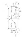
底部14は、上端開口部が胴部13の下端開口部に接続されたヒール部17と、ヒール部17の下端開口部を閉塞し、かつ外周縁部が接地部18とされた底壁部19と、を備えるカップ状に形成されている。
ヒール部17には、第3環状凹溝20と同じ深さの第4環状凹溝31が全周に亘って連続して形成されている。A third
The
In the
さらに、本実施形態では、ヒール部17の外周面、および胴部13の下端部の外周面に凹凸部17aが形成されている。これにより、充填工程において、ボトル1を多数本連立させて搬送している際に、隣り合うボトル1のヒール部17の外周面同士、および胴部13の下端部の外周面同士が互いに密接し合い滑り難くなることが抑えられ、いわゆるブロッキングの発生が抑制される。なお、図示の例では、第3環状凹溝20の表面および第4環状凹溝31の表面にも凹凸部17aが形成されている。 Further, in the present embodiment, the
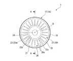
底壁部19は、図3に示すように、接地部18に径方向内側から連なり上方に向けて延びる立ち上がり周壁部21と、立ち上がり周壁部21の上端部から径方向の内側に向けて突出する環状の可動壁部22と、可動壁部22の径方向の内端部から上方に向けて延びる陥没周壁部23と、を備えている。 As shown in FIG. 3, the
立ち上がり周壁部21は、下方から上方に向かうに従い漸次縮径している。
可動壁部22は、下方に向けて突の曲面状に形成されるとともに、径方向の外側から内側に向かうに従い漸次下方に向けて延在している。この可動壁部22と立ち上がり周壁部21とは上方に向けて突の曲面部25を介して連結されている。そして、可動壁部22は、陥没周壁部23を上方に向けて移動させるように、曲面部(立ち上がり周壁部21との接続部分)25を中心に回動自在となっている。なお、可動壁部22の高低差H(陥没周壁部23との接続部分近傍から曲面部25までのボトル軸O方向における長さ)は、可動壁部22の直径Dの5%以上に設定されている(H/D≧0.05)。これにより、可動壁部22を移動(回動)させ易くすることができるとともに、移動量を大きく確保することができる。The rising
The
可動壁部22には、複数のリブ26がボトル軸Oを中心に放射状に配設されている。すなわち、各リブ26は、周方向に沿って等間隔に配設されている。図示の例では、リブ26は、上方に向けて曲面状に窪んだ複数の凹部26aが径方向に沿って断続的に、かつ真直ぐ延在して構成されている。これにより、リブ26は、周方向に沿う縦断面視形状が波形状に形成される。
各凹部26aは、それぞれ同形同大に形成され、径方向に沿って等間隔に配置されている。そして、複数のリブ26各々において、複数の凹部26aが配設されている径方向に沿う各位置は同じになっている。なお、各リブ26において、複数の凹部26aのうち、最も径方向の外側に位置する凹部26aは、曲面部25に径方向の内側から近接し、最も径方向内側に位置する凹部26aは、陥没周壁部23に径方向外側から近接している。A plurality of
The
陥没周壁部23は、ボトル軸Oと同軸に配設されるとともに、上方から下方に向かうに従い漸次拡径している。陥没周壁部23の上端部には、ボトル軸Oと同軸に配置された円板状の頂壁24が接続されており、陥没周壁部23および頂壁24の全体で有頂筒状をなしている。なお、陥没周壁部23は、横断面視円形状に形成されている。また、陥没周壁部23は、径方向の内側に向けて突の曲面状に形成された湾曲壁部23aの上端が頂壁24に、湾曲壁部23aの下端が屈曲部23bを介して傾斜壁部23cに連接されて構成されている。傾斜壁部23cは、上方から下方に向かうに従い漸次拡径し、その下端が環状の可動壁部22の径方向における内端部に連接されている。 The depressed
そして、本実施形態では、ヒール部17のうち、接地部18に径方向の外側から連なるヒール下端部27は、該ヒール下端部27に上方から連なる上ヒール部28より小径に形成されている。なお、上ヒール部28は、胴部13のボトル軸O方向両端部とともに、ボトル1の最大外径部となっている。 In the present embodiment, in the
さらに本実施形態では、ヒール下端部27と上ヒール部28との連結部分29は、上方から下方に向かうに従い漸次縮径されている。また、この連結部分の縦断面視形状は、上方から下方に向けて直線状に延在している。 Furthermore, in the present embodiment, the connecting
このように構成されたボトル1内が減圧すると、底壁部19の曲面部25を中心にして可動壁部22が上方に向かって回動することで、可動壁部22は、陥没周壁部23を上方に向けて持ち上げるように移動する。すなわち、減圧時にボトル1の底壁部19を積極的に変形させることで、胴部13等の変形を伴うことなく、ボトル1の内圧変化(減圧)を吸収することができる。この場合、立ち上がり周壁部21と可動壁部22との接続部分を、上方に向けて突の曲面部25に形成することで、立ち上がり周壁部21の上端部を中心にして可動壁部22を移動(回動)させ易くすることができる。そのため、ボトル1の内圧変化に応じて可動壁部22を柔軟に変形させることができる。 When the inside of the
特に、本実施形態では、底壁部19の可動壁部22に複数のリブ26を形成することで、可動壁部22の表面積を増加させることができる。これにより、可動壁部22における受圧面積を増加できるため、可動壁部22がボトル1の内圧変化に速やかに対応して変形する。したがって、ボトル1の減圧吸収性能を向上させることができる。
しかも、本実施形態のリブ26は、ボトル軸Oを中心にして放射状に配設されているため、可動壁部22の全域を均等に変形させることが可能になる。これにより、減圧吸収性能をより高めることができる。In particular, in the present embodiment, the surface area of the
Moreover, since the
さらに、本実施形態のリブ26は、複数の凹部26aを径方向に沿って断続的に延在させて構成されているため、リブ26の表面積を効果的に増加させることができる。これにより、可動壁部22の受圧面積をさらに増加できる。さらに、ボトル1の内圧変化に応じて可動壁部22を柔軟に変形させることができる。 Furthermore, since the
また、リブ26(凹部26a)が減圧時における可動壁部22の変形方向である上方に向けて窪んだ凹形状に形成されているので、可動壁部22の内圧変化に応じて可動壁部22を確実に変形させることができる。 Further, since the rib 26 (
ここで、本願発明者は、図4に示すように、可動壁部22のうち、周方向で隣接するリブ26同士の中心間に位置する部分の最外周(曲面部25との連接部)における周長Tに対する、リブ26の周方向における幅W(凹部26aの直径)の割合(以下、リブ幅比率K=W/Tという)を変化させ、それぞれの条件において減圧強度(kPa)と吸収容量(ml)との関係がどのように変化するかを解析した。
また、本解析における凹部26aは全て同形同大の半球状としている。なお、リブ26が径方向で連続的に形成されている場合は、その周方向の幅をリブ幅Wとする。径方向で連続的に設けられたリブ26の場合は、前記リブ幅Wを一定としている。Here, as shown in FIG. 4, the inventor of the present application, in the
In addition, all the
本解析において、リブ幅比率Kの変更は、リブ26の幅Wは変化させずに、可動壁部22に放射状に形成されたリブ26の本数、すなわち隣接するリブ26の中心間における周長Tを変化させることで行った。具体的な条件は、以下の実施例1〜3、および比較例1,2の通りである。なお、本解析に用いたボトルは、上述した実施形態と同様の構成で、内容量が500mlのボトル1である。
<実施例1>リブ8本(リブ幅比率K=0.132)
<実施例2>リブ12本(リブ幅比率K=0.198)
<実施例3>リブ24本(リブ幅比率K=0.396)
<比較例1>リブ6本(リブ幅比率K=0.099)
<比較例2>リブ7本(リブ幅比率K=0.116)In this analysis, the rib width ratio K is changed by changing the number W of the
<Example 1> Eight ribs (rib width ratio K = 0.132)
<Example 2> 12 ribs (rib width ratio K = 0.198)
<Example 3> 24 ribs (rib width ratio K = 0.396)
<Comparative example 1> Six ribs (rib width ratio K = 0.099)
<Comparative example 2> Seven ribs (rib width ratio K = 0.116)
まず、実施例1〜3及び比較例1,2の何れの場合においても、ボトル1内を減圧していくと、減圧強度の増加に伴って減圧吸収容量が徐々に増加することが確認できた。これは、ボトル1内の減圧によって、可動壁部22が少なくとも部分的に立ち上がり周壁部21の上端部を中心にして回動することで、可動壁部22が陥没周壁部23を上方に向けて持ち上げるように移動したためと考えられる。 First, in any case of Examples 1 to 3 and Comparative Examples 1 and 2, it was confirmed that when the inside of the
その後、さらに減圧強度を増加させると、実施例1〜3の場合には、減圧強度の増加途中で減圧吸収容量が急激に増加したことが確認された。これは、ボトル減圧時に、可動壁部22に局所的に大きな応力が作用する部分が生じ(例えば、放射状に形成された複数のリブ26のうちの一つ、又はその近傍に生じる)、この応力が直近のリブ26に伝播することで、可動壁部22が全周に亘って反転変形するものと考えられる。このように、実施例1〜3では、可動壁部22の全体が反転変形することで可動壁部22の上方への移動量が急増し、これに追従して陥没周壁部23がさらに上方に移動したため、上述したような結果が得られたと考えられる。 Thereafter, when the reduced pressure strength was further increased, in the case of Examples 1 to 3, it was confirmed that the reduced pressure absorption capacity increased rapidly during the increase of the reduced pressure strength. This is because a portion where a large stress acts locally on the
一方、比較例1,2の場合には、可動壁部22の全体が反転変形せず、減圧吸収容量の急増は確認できなかった。なお、この場合には、可動壁部22が反転変形するよりも前に、ボトル1の胴部13等が変形してしまうことも考えられる。 On the other hand, in the case of Comparative Examples 1 and 2, the entire
以上のことから、可動壁部22の反転変形による減圧吸収性能を確実に発揮させるためには、リブ26の本数が比較的多いこと、すなわち周方向で隣接するリブ26間の距離が比較的近いことが好ましい。具体的に、可動壁部23のうち、周方向で隣接するリブ26同士の中心間に位置する部分の最外周(曲面部25との連接部)における周長Tに対する、リブ26の周方向における幅W(凹部26aの直径)の割合が0.12以上になっていることが好ましい(リブ幅比率K≧0.12)。
この構成によれば、周方向で隣接するリブ26間の距離を比較的近くできるので、局所的な応力を直近のリブ26に確実に伝播させることができるため、可動壁部22を全周に亘って確実に反転変形させることができ、減圧吸収性能を確実に発揮させることができる。From the above, in order to reliably exhibit the reduced pressure absorption performance due to the reverse deformation of the
According to this configuration, since the distance between the
以上、本発明の実施形態について図面を参照して詳述したが、具体的な構成はこの実施形態に限られるものではなく、本発明の要旨を逸脱しない範囲の設計変更等も含まれる。 As mentioned above, although embodiment of this invention was explained in full detail with reference to drawings, the concrete structure is not restricted to this embodiment, The design change etc. of the range which does not deviate from the summary of this invention are included.
例えば、前記実施形態では、リブ26を放射状に断続的に延在させたが、これに限らず、連続的に延在させてもよいし、湾曲して延在させてもよい。
また、リブ26(凹部26a)の形状は、円形に限らず、矩形状等、適宜設計変更が可能である。さらに凹部26aの大きさを変更しても構わない。この場合、凹部26aを径方向内方側から径方向外方側に向かうにつれて、漸次大きくなるように配置する等、適宜変更可能である。
また、立ち上がり周壁部21は、例えばボトル軸O方向に沿って平行に延在させる等、適宜変更してもよい。
また、可動壁部22は、例えばボトル径方向に沿って平行に突出させる等、適宜変更してもよい。
さらに、陥没周壁部23は、例えばボトル軸O方向に沿って平行に延在させる等、適宜変更してもよい。
さらに、凹凸部17aを形成しなくてもよい。For example, in the above-described embodiment, the
The shape of the rib 26 (recessed
The rising
Moreover, you may change the
Further, the depressed
Furthermore, the
また、ボトル1を形成する合成樹脂材料は、例えばポリエチレンテレフタレートや、ポリエチレンナフタレート、非晶性ポリエステル等、またはこれらのブレンド材料等、適宜変更してもよい。
さらに、ボトル1は単層構造体に限らず中間層を有する積層構造体としてもよい。この中間層としては、例えばガスバリア性を有する樹脂材料からなる層、再生材からなる層、若しくは酸素吸収性を有する樹脂材料からなる層等が挙げられる。
また、前記実施形態では、肩部12、胴部13および底部14のそれぞれのボトル軸Oに直交する横断面視形状を円形状としたが、これに限らず例えば、多角形状にする等適宜変更してもよい。The synthetic resin material forming the
Further, the
Moreover, in the said embodiment, although the cross-sectional view shape orthogonal to each bottle axis | shaft O of the
その他、本発明の趣旨を逸脱しない範囲で、前記実施形態における構成要素を周知の構成要素に置き換えることは適宜可能であり、また、前記変形例を適宜組み合わせてもよい。 In addition, it is possible to appropriately replace the constituent elements in the embodiment with known constituent elements without departing from the spirit of the present invention, and the modification examples may be combined as appropriate.
1…ボトル
14…底部
18…接地部
19…底壁部
21…立ち上がり周壁部
22…可動壁部
23…陥没周壁部
25…曲面部
26…リブDESCRIPTION OF
Claims (4)
Translated fromJapanese底部の底壁部が、
外周縁部に位置する接地部と、
該接地部にボトル径方向の内側から連なり上方に向けて延びる立ち上がり周壁部と、
該立ち上がり周壁部の上端部からボトル径方向の内側に向けて突出する可動壁部と、
該可動壁部のボトル径方向の内端部から上方に向けて延びる陥没周壁部と、を備え、
前記可動壁部は、前記立ち上がり周壁部との接続部分を中心に前記陥没周壁部とともに上方に向けて移動自在に配設され、
前記可動壁部には、複数のリブがボトル軸を中心に放射状に配設されていることを特徴とするボトル。A bottomed cylindrical bottle formed of a synthetic resin material,
The bottom wall of the bottom
A grounding portion located at the outer periphery,
A rising peripheral wall portion extending from the inside in the bottle radial direction to the grounding portion and extending upward;
A movable wall portion protruding from the upper end of the rising peripheral wall portion toward the inside in the bottle radial direction;
A depressed peripheral wall portion extending upward from an inner end portion in the bottle radial direction of the movable wall portion,
The movable wall portion is disposed so as to be movable upward together with the depressed peripheral wall portion around a connection portion with the rising peripheral wall portion,
A bottle characterized in that a plurality of ribs are radially arranged around the bottle axis on the movable wall portion.
Priority Applications (9)
| Application Number | Priority Date | Filing Date | Title |
|---|---|---|---|
| JP2010267385AJP2012091860A (en) | 2010-09-30 | 2010-11-30 | Bottle |
| PCT/JP2011/071577WO2012043362A1 (en) | 2010-09-30 | 2011-09-22 | Bottle |
| AU2011309311AAU2011309311B2 (en) | 2010-09-30 | 2011-09-22 | Bottle |
| CA2811710ACA2811710C (en) | 2010-09-30 | 2011-09-22 | Bottle |
| CN201180045761.3ACN103153797B (en) | 2010-09-30 | 2011-09-22 | Bottle |
| KR1020137006581AKR101818078B1 (en) | 2010-09-30 | 2011-09-22 | Bottle |
| US13/823,552US9650207B2 (en) | 2010-09-30 | 2011-09-22 | Cylindrical bottle with bottom |
| EP11828919.8AEP2623427B1 (en) | 2010-09-30 | 2011-09-22 | Bottle |
| TW100134661ATWI527737B (en) | 2010-09-30 | 2011-09-26 | Bottle |
Applications Claiming Priority (3)
| Application Number | Priority Date | Filing Date | Title |
|---|---|---|---|
| JP2010220704 | 2010-09-30 | ||
| JP2010220704 | 2010-09-30 | ||
| JP2010267385AJP2012091860A (en) | 2010-09-30 | 2010-11-30 | Bottle |
Publications (1)
| Publication Number | Publication Date |
|---|---|
| JP2012091860Atrue JP2012091860A (en) | 2012-05-17 |
Family
ID=45892813
Family Applications (1)
| Application Number | Title | Priority Date | Filing Date |
|---|---|---|---|
| JP2010267385APendingJP2012091860A (en) | 2010-09-30 | 2010-11-30 | Bottle |
Country Status (9)
| Country | Link |
|---|---|
| US (1) | US9650207B2 (en) |
| EP (1) | EP2623427B1 (en) |
| JP (1) | JP2012091860A (en) |
| KR (1) | KR101818078B1 (en) |
| CN (1) | CN103153797B (en) |
| AU (1) | AU2011309311B2 (en) |
| CA (1) | CA2811710C (en) |
| TW (1) | TWI527737B (en) |
| WO (1) | WO2012043362A1 (en) |
Cited By (5)
| Publication number | Priority date | Publication date | Assignee | Title |
|---|---|---|---|---|
| JP2014088210A (en)* | 2012-10-31 | 2014-05-15 | Yoshino Kogyosho Co Ltd | Bottle |
| JP2014193737A (en)* | 2013-03-29 | 2014-10-09 | Yoshino Kogyosho Co Ltd | Bottle |
| WO2015166682A1 (en)* | 2014-04-30 | 2015-11-05 | 株式会社吉野工業所 | Bottle |
| JP2016534950A (en)* | 2013-11-05 | 2016-11-10 | アムコー リミテッド | High temperature filling container |
| JP2017178381A (en)* | 2016-03-30 | 2017-10-05 | 株式会社吉野工業所 | Synthetic resin bottle |
Families Citing this family (8)
| Publication number | Priority date | Publication date | Assignee | Title |
|---|---|---|---|---|
| US9751679B2 (en) | 2003-05-23 | 2017-09-05 | Amcor Limited | Vacuum absorbing bases for hot-fill containers |
| US9346610B2 (en)* | 2013-03-14 | 2016-05-24 | James Nelson | Variable volume container |
| US10703024B2 (en)* | 2014-04-11 | 2020-07-07 | Dak Americas Llc | EBM ePET container drop-impact enhancement |
| EP3109176A1 (en)* | 2015-06-23 | 2016-12-28 | Sidel Participations | Container provided with a curved invertible diaphragm |
| CA2999296A1 (en)* | 2017-03-27 | 2018-09-27 | Yoshino Kogyosho Co., Ltd. | Pressure reduction-absorbing bottle |
| JP7114276B2 (en) | 2018-03-05 | 2022-08-08 | サントリーホールディングス株式会社 | plastic bottle |
| US11970324B2 (en) | 2022-06-06 | 2024-04-30 | Envases USA, Inc. | Base of a plastic container |
| US20240294296A1 (en)* | 2023-03-02 | 2024-09-05 | Starbucks Corporation | Systems, methods, and devices for beverage containers with a foamed base |
Citations (2)
| Publication number | Priority date | Publication date | Assignee | Title |
|---|---|---|---|---|
| WO2010056517A1 (en)* | 2008-11-17 | 2010-05-20 | Amcor Limited | Container base structure responsive to vacuum related forces |
| WO2010061758A1 (en)* | 2008-11-27 | 2010-06-03 | 株式会社 吉野工業所 | Synthetic resin bottle |
Family Cites Families (12)
| Publication number | Priority date | Publication date | Assignee | Title |
|---|---|---|---|---|
| JPH0678093B2 (en) | 1986-03-27 | 1994-10-05 | 大日本印刷株式会社 | Bottle body made of saturated polyester resin |
| US4785949A (en)* | 1987-12-11 | 1988-11-22 | Continental Pet Technologies, Inc. | Base configuration for an internally pressurized container |
| JPH07112729A (en) | 1993-10-13 | 1995-05-02 | Toppan Printing Co Ltd | Heat resistant plastic container |
| US5503283A (en)* | 1994-11-14 | 1996-04-02 | Graham Packaging Corporation | Blow-molded container base structure |
| US6065624A (en)* | 1998-10-29 | 2000-05-23 | Plastipak Packaging, Inc. | Plastic blow molded water bottle |
| US7543713B2 (en)* | 2001-04-19 | 2009-06-09 | Graham Packaging Company L.P. | Multi-functional base for a plastic, wide-mouth, blow-molded container |
| US7900425B2 (en) | 2005-10-14 | 2011-03-08 | Graham Packaging Company, L.P. | Method for handling a hot-filled container having a moveable portion to reduce a portion of a vacuum created therein |
| US6634517B2 (en)* | 2001-09-17 | 2003-10-21 | Crown Cork & Seal Technologies Corporation | Base for plastic container |
| TWI375641B (en) | 2004-12-20 | 2012-11-01 | Co2 Pac Ltd | A method of processing a container and base cup structure for removal of vacuum pressure |
| JP2007290772A (en) | 2006-04-27 | 2007-11-08 | Hokkai Can Co Ltd | Synthetic resin bottle and method for producing synthetic resin bottle |
| CA2719488C (en)* | 2008-03-27 | 2016-07-12 | Constar International, Inc. | Container base having volume absorption panel |
| JP5316940B2 (en)* | 2008-11-27 | 2013-10-16 | 株式会社吉野工業所 | Synthetic resin housing |
- 2010
- 2010-11-30JPJP2010267385Apatent/JP2012091860A/enactivePending
- 2011
- 2011-09-22AUAU2011309311Apatent/AU2011309311B2/ennot_activeCeased
- 2011-09-22USUS13/823,552patent/US9650207B2/enactiveActive
- 2011-09-22WOPCT/JP2011/071577patent/WO2012043362A1/enactiveApplication Filing
- 2011-09-22CACA2811710Apatent/CA2811710C/enactiveActive
- 2011-09-22EPEP11828919.8Apatent/EP2623427B1/enactiveActive
- 2011-09-22CNCN201180045761.3Apatent/CN103153797B/enactiveActive
- 2011-09-22KRKR1020137006581Apatent/KR101818078B1/enactiveActive
- 2011-09-26TWTW100134661Apatent/TWI527737B/ennot_activeIP Right Cessation
Patent Citations (2)
| Publication number | Priority date | Publication date | Assignee | Title |
|---|---|---|---|---|
| WO2010056517A1 (en)* | 2008-11-17 | 2010-05-20 | Amcor Limited | Container base structure responsive to vacuum related forces |
| WO2010061758A1 (en)* | 2008-11-27 | 2010-06-03 | 株式会社 吉野工業所 | Synthetic resin bottle |
Cited By (9)
| Publication number | Priority date | Publication date | Assignee | Title |
|---|---|---|---|---|
| JP2014088210A (en)* | 2012-10-31 | 2014-05-15 | Yoshino Kogyosho Co Ltd | Bottle |
| JP2014193737A (en)* | 2013-03-29 | 2014-10-09 | Yoshino Kogyosho Co Ltd | Bottle |
| JP2016534950A (en)* | 2013-11-05 | 2016-11-10 | アムコー リミテッド | High temperature filling container |
| WO2015166682A1 (en)* | 2014-04-30 | 2015-11-05 | 株式会社吉野工業所 | Bottle |
| JP2015209240A (en)* | 2014-04-30 | 2015-11-24 | 株式会社吉野工業所 | bottle |
| KR20170005408A (en) | 2014-04-30 | 2017-01-13 | 가부시키가이샤 요시노 고교쇼 | bottle |
| US10167127B2 (en) | 2014-04-30 | 2019-01-01 | Yoshino Kogyosho Co., Ltd. | Cylindrical bottle with bottom |
| JP2017178381A (en)* | 2016-03-30 | 2017-10-05 | 株式会社吉野工業所 | Synthetic resin bottle |
| EP3225562B1 (en)* | 2016-03-30 | 2023-09-20 | Yoshino Kogyosho Co., Ltd. | Synthetic resin bottle |
Also Published As
| Publication number | Publication date |
|---|---|
| EP2623427A1 (en) | 2013-08-07 |
| TW201221433A (en) | 2012-06-01 |
| US9650207B2 (en) | 2017-05-16 |
| KR101818078B1 (en) | 2018-01-12 |
| CA2811710A1 (en) | 2012-04-05 |
| CA2811710C (en) | 2018-05-22 |
| AU2011309311A1 (en) | 2013-04-11 |
| US20130180998A1 (en) | 2013-07-18 |
| AU2011309311B2 (en) | 2016-06-09 |
| TWI527737B (en) | 2016-04-01 |
| KR20140125279A (en) | 2014-10-28 |
| EP2623427A4 (en) | 2014-03-26 |
| CN103153797B (en) | 2015-02-25 |
| WO2012043362A1 (en) | 2012-04-05 |
| EP2623427B1 (en) | 2017-05-31 |
| CN103153797A (en) | 2013-06-12 |
Similar Documents
| Publication | Publication Date | Title |
|---|---|---|
| JP2012091860A (en) | Bottle | |
| JP6397652B2 (en) | Bottle | |
| WO2012057026A1 (en) | Bottle | |
| JP2012076746A (en) | Bottle | |
| WO2012147885A1 (en) | Bottle | |
| JP5719677B2 (en) | Bottle | |
| JP5785823B2 (en) | Bottle | |
| JP5793300B2 (en) | Bottle | |
| JP5650520B2 (en) | Bottle | |
| JP5684534B2 (en) | Bottle | |
| JP5645604B2 (en) | Bottle | |
| JP5489953B2 (en) | Bottle | |
| JP2012076747A (en) | Bottle | |
| JP6151881B2 (en) | Blow bottle | |
| JP5645602B2 (en) | Bottle | |
| JP2012091827A (en) | Bottle | |
| JP2014105002A (en) | Bottle | |
| JP2012091816A (en) | Bottle |
Legal Events
| Date | Code | Title | Description |
|---|---|---|---|
| A621 | Written request for application examination | Free format text:JAPANESE INTERMEDIATE CODE: A621 Effective date:20130531 | |
| A131 | Notification of reasons for refusal | Free format text:JAPANESE INTERMEDIATE CODE: A131 Effective date:20140513 | |
| A521 | Written amendment | Free format text:JAPANESE INTERMEDIATE CODE: A523 Effective date:20140609 | |
| A02 | Decision of refusal | Free format text:JAPANESE INTERMEDIATE CODE: A02 Effective date:20150203 | |
| A521 | Written amendment | Free format text:JAPANESE INTERMEDIATE CODE: A523 Effective date:20150408 | |
| A911 | Transfer to examiner for re-examination before appeal (zenchi) | Free format text:JAPANESE INTERMEDIATE CODE: A911 Effective date:20150416 | |
| A912 | Re-examination (zenchi) completed and case transferred to appeal board | Free format text:JAPANESE INTERMEDIATE CODE: A912 Effective date:20150703 |