JP2012090194A - Network system - Google Patents
Network systemDownload PDFInfo
- Publication number
- JP2012090194A JP2012090194AJP2010236982AJP2010236982AJP2012090194AJP 2012090194 AJP2012090194 AJP 2012090194AJP 2010236982 AJP2010236982 AJP 2010236982AJP 2010236982 AJP2010236982 AJP 2010236982AJP 2012090194 AJP2012090194 AJP 2012090194A
- Authority
- JP
- Japan
- Prior art keywords
- server device
- server
- field
- address
- service providing
- Prior art date
- Legal status (The legal status is an assumption and is not a legal conclusion. Google has not performed a legal analysis and makes no representation as to the accuracy of the status listed.)
- Granted
Links
Images


Classifications
- H—ELECTRICITY
- H04—ELECTRIC COMMUNICATION TECHNIQUE
- H04L—TRANSMISSION OF DIGITAL INFORMATION, e.g. TELEGRAPHIC COMMUNICATION
- H04L67/00—Network arrangements or protocols for supporting network services or applications
- H04L67/01—Protocols
- H04L67/10—Protocols in which an application is distributed across nodes in the network
- H04L67/1001—Protocols in which an application is distributed across nodes in the network for accessing one among a plurality of replicated servers
- H04L67/1004—Server selection for load balancing
- H04L67/1008—Server selection for load balancing based on parameters of servers, e.g. available memory or workload
- H—ELECTRICITY
- H04—ELECTRIC COMMUNICATION TECHNIQUE
- H04L—TRANSMISSION OF DIGITAL INFORMATION, e.g. TELEGRAPHIC COMMUNICATION
- H04L61/00—Network arrangements, protocols or services for addressing or naming
- H04L61/45—Network directories; Name-to-address mapping
- H04L61/4505—Network directories; Name-to-address mapping using standardised directories; using standardised directory access protocols
- H04L61/4511—Network directories; Name-to-address mapping using standardised directories; using standardised directory access protocols using domain name system [DNS]
- H—ELECTRICITY
- H04—ELECTRIC COMMUNICATION TECHNIQUE
- H04L—TRANSMISSION OF DIGITAL INFORMATION, e.g. TELEGRAPHIC COMMUNICATION
- H04L67/00—Network arrangements or protocols for supporting network services or applications
- H04L67/01—Protocols
- H04L67/10—Protocols in which an application is distributed across nodes in the network
- H04L67/1001—Protocols in which an application is distributed across nodes in the network for accessing one among a plurality of replicated servers
- H04L67/1031—Controlling of the operation of servers by a load balancer, e.g. adding or removing servers that serve requests
- H—ELECTRICITY
- H04—ELECTRIC COMMUNICATION TECHNIQUE
- H04L—TRANSMISSION OF DIGITAL INFORMATION, e.g. TELEGRAPHIC COMMUNICATION
- H04L67/00—Network arrangements or protocols for supporting network services or applications
- H04L67/01—Protocols
- H04L67/10—Protocols in which an application is distributed across nodes in the network
- H04L67/1001—Protocols in which an application is distributed across nodes in the network for accessing one among a plurality of replicated servers
- H04L67/1034—Reaction to server failures by a load balancer
Landscapes
- Engineering & Computer Science (AREA)
- Computer Networks & Wireless Communication (AREA)
- Signal Processing (AREA)
- Computer Hardware Design (AREA)
- General Engineering & Computer Science (AREA)
- Computer And Data Communications (AREA)
- Data Exchanges In Wide-Area Networks (AREA)
Abstract
Description
Translated fromJapanese本発明は、クライアント端末からのサービス要求に対し、安定したサービスを提供するネットワークシステムに関するものである。 The present invention relates to a network system that provides a stable service in response to a service request from a client terminal.
IPネットワーク環境において、クライアント端末からサーバ装置への名前解決処理を行うためのドメインネームシステム(DNS)において、複数台存在しているサーバ装置を仮想的に1台のサーバであるかのようにクライアント端末に見せかけ、更にサーバの負荷分散を行う、DNSラウンドロビンと呼ばれる技術が存在する。 In an IP network environment, in a domain name system (DNS) for performing name resolution processing from a client terminal to a server device, a plurality of server devices exist as if they were virtually one server There is a technology called DNS round robin that pretends to be a terminal and further distributes the load on the server.
さらに、DNSラウンドロビン技術を発展させた技術としては、DNSサーバが、サーバ装置の負荷状態を監視し、負荷の軽いサーバ装置のIPアドレスを応答するといった、米国特許第7284051号公報に記載のDNSシステム技術がある(特許文献1)。 Further, as a technology developed from the DNS round robin technology, a DNS server described in US Pat. No. 7,284,051 in which a DNS server monitors a load state of a server device and responds with an IP address of a lightly loaded server device. There is a system technology (Patent Document 1).
この公報には、「A relaying apparatus comprises a client terminal, many server terminals connected via network to the client terminal, a DNS responding device which accepts a DNS inquiry from the client terminal via a client-side DNS device, and one path load measuring device for each of the server terminals which measures a load in the communication path up to the client-side DNS device. The DNS responding device distributes a work load by routing a service request from the client terminal to any one of the server terminals based on the measurement result (i.e. route load). 」(abstract)と記載されている。 This publication states that `` A relaying apparatus comprises a client terminal, many server terminals connected via network to the client terminal, a DNS responding device which accepts a DNS inquiry from the client terminal via a client-side DNS device, and one path load. measuring device for each of the server terminals which measures a load in the communication path up to the client-side DNS device.The DNS responding device distributes a work load by routing a service request from the client terminal to any one of the server terminals based. on the measurement result (ie route load). ”(abstract).
特許文献1が開示する技術は、クライアント端末からのサービス要求を複数台のサーバ装置に分散させる技術であり、クライアント端末からの名前解決要求時に、特に負荷の軽いサーバ装置のIPアドレスを応答することで、負荷を均等化させようとするものである。しかし、この技術では、サーバ装置が均等に高負荷になったり、そのために輻輳もしくはサービス不能な状態になった場合にも、サーバ装置にクライアント端末からのサービス要求が届いてしまい、ますます状況が悪化するという課題がある。 The technology disclosed in
上記課題を解決するために、本明細書においては、例えば、ドメインネームシステム(DNS)サーバ装置と、一つ以上のサービス提供サーバ装置と、Sorryサーバ装置とがネットワークで接続され、クライアント端末に対し前記ネットワークを経由してサービス提供を行うネットワークシステムが開示される。 In order to solve the above-described problem, in this specification, for example, a domain name system (DNS) server device, one or more service providing server devices, and a sorry server device are connected via a network and are connected to a client terminal. A network system for providing a service via the network is disclosed.
本明細書において開示されるDNSサーバ装置は、クライアント端末に対して、DNSサービス、即ち名前解決処理サービスを提供する。また、繰り返し、例えば定期的に、サービス提供サーバ装置の死活状態(すなわち、アクティブ状態/非アクティブ状態)の監視、及び負荷情報の収集を行い、名前解決処理時に、収集した死活状態及び負荷情報に応じて、どのサービス提供サーバ装置のIPアドレスを応答するかを決定する、という特徴を備える。 The DNS server device disclosed in this specification provides a DNS service, that is, a name resolution processing service to a client terminal. Also, repeatedly, for example, periodically monitor the alive state (that is, active state / inactive state) of the service providing server device and collect load information, and collect the alive state and load information during the name resolution process. In response, the service providing server device is characterized in that it determines which IP address of the service providing server device to respond to.
なお、サービス提供サーバ装置は、クライアント端末に対し、WebサービスやProxyサービスを提供するものであり、Sorryサーバ装置は、クライアント端末からHTTPアクセスを受信すると、要求されたサービスを提供できない旨を示すメッセージを応答するものである。 Note that the service providing server device provides a Web service or a proxy service to the client terminal, and when the sorry server device receives the HTTP access from the client terminal, a message indicating that the requested service cannot be provided. Is a response.
本明細書において開示されるDNSサーバ装置は、具体的には、名前解決処理の結果、該当するサービス提供サーバ装置がアクティブだが輻輳している場合、もしくは非アクティブの場合に、Sorryサーバ装置に割り付けられたIPアドレスを応答する手段を備えることを特徴とする。 Specifically, the DNS server device disclosed in this specification is allocated to the sorry server device when the corresponding service providing server device is active but congested or inactive as a result of the name resolution process. Means for responding to the received IP address.
また、本明細書において開示されるDNSサーバ装置は、具体的には、あるサーバ装置がアクティブ状態だが輻輳している場合や、もしくは非アクティブ状態の場合に、スタンバイ状態になっている別のサーバ装置に対し、起動するためのサーバ起動命令と、サービス用のIPアドレスを送信する、サーバ遠隔起動処理を備えることを特徴とする。 Further, the DNS server device disclosed in the present specification specifically refers to another server that is in a standby state when a certain server device is active but congested or inactive. A server remote activation process for transmitting a server activation command for activation and an IP address for service to the apparatus is provided.
さらに、DNSサーバ装置は、サービス提供サーバ装置の代表ドメイン名ごとの情報を管理するサーバ情報管理テーブルを備え、サービス提供サーバ装置の死活状態監視処理と負荷情報収集処理とを繰り返し行うサーバ監視処理を行い、サーバ監視処理結果をサーバ情報管理テーブルに記録するように構成しても良く、
サービス提供サーバ装置は、DNSサーバ装置からの負荷情報収集要求に対して、自サーバ装置に設定されている仮想IPアドレス毎に、クライアント端末から接続されているTCP接続の接続数を応答する負荷情報応答処理を行うように構成しても良い。Further, the DNS server device includes a server information management table that manages information for each representative domain name of the service providing server device, and performs server monitoring processing that repeatedly performs the alive state monitoring processing and load information collection processing of the service providing server device. And the server monitoring process result may be recorded in the server information management table.
In response to a load information collection request from the DNS server device, the service providing server device responds with the number of TCP connections connected from the client terminal for each virtual IP address set in the server device itself. You may comprise so that a response process may be performed.
DNSサーバ装置がSorryサーバ装置のIPアドレスを応答することで、サーバ装置が輻輳もしくはサービス不能な状態の場合に、それ以上サーバ装置に、新規に接続してくるクライアント端末からのアクセスを抑制する。これによりサーバ装置の更なる輻輳を回避することができる。 Since the DNS server device responds with the IP address of the sorry server device, when the server device is congested or in a service-incapable state, further access from client terminals newly connected to the server device is suppressed. Thereby, further congestion of the server device can be avoided.
また、DNSサーバ装置は、サーバ装置が輻輳もしくはサービス不能な状態の場合に、スタンバイ状態のサーバ装置に対し、新しくサーバ処理を開始させ、新規に接続してくるクライアント端末からのアクセスを新サーバ装置に振り分けることで、トラフィックが急上昇した場合でも、ユーザに対して、サービスを停止させずに処理を継続することができる。 In addition, when the server device is congested or incapable of service, the DNS server device starts a new server process for the server device in the standby state, and accesses from the newly connected client terminal to the new server device. By allocating to, processing can be continued without stopping the service for the user even when traffic rapidly increases.
サーバ装置が輻輳もしくはサービス不能な状態になった場合であっても、更なる輻輳を回避したり、サービスを停止させずに処理を継続したり、することが可能になる。 Even when the server device is congested or incapable of service, it becomes possible to avoid further congestion and to continue processing without stopping the service.
以下、実施例を、図面を用いて説明する。 Hereinafter, examples will be described with reference to the drawings.
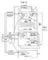
図1は、本発明に関わるネットワークシステムの第1の構成例を示すブロック図である。 FIG. 1 is a block diagram showing a first configuration example of a network system according to the present invention.
図1において、クライアント端末10、DNSサーバ装置20、一つ以上のサーバ装置30、及びSorryサーバ装置40は、それぞれLAN(Local Area Network)や無線ネットワークなどのネットワーク50に接続されており、ネットワーク50を経由して遠隔からの接続が可能な状態にある。 In FIG. 1, a
クライアント端末10は、HTTP(HyperText Transfer Protocol)などのTCP/IP上のプロトコルを用いてサーバ装置30に接続し、サービス要求を行うユーザ端末である。クライアント端末10は、サーバ装置30にアクセスする前に、DNSサーバ装置20に対して、DNSプロトコルを用いて、サーバ装置30の代表ドメイン名の名前解決要求を送信する。そして、その応答としてサーバ装置30のIPアドレスを受信する。 The
DNSサーバ装置20は、名前解決サービスを提供するサーバ装置である。 The
DNSサーバ装置20は、繰り返し(例えば定期的に)、サーバ装置30の死活状態の監視、及び負荷情報の収集を行う。そして、サーバ装置30の名前解決時に、サーバ装置30の死活状態及び負荷情報に応じて、どのIPアドレスを応答するかを決定する。また、サーバ装置30がアクティブだが輻輳している場合や、もしくは非アクティブの場合に、Sorryサーバ装置40に割り付けられたIPアドレスを応答する。 The
Sorryサーバ装置40は、クライアント端末10からHTTPアクセスを受信すると、常に、システムが輻輳に陥っている旨をユーザに知らせるメッセージを応答するサーバ装置である。本処理は、Sorryサーバ処理部41にて行う。前述のメッセージは、例えば「本サービスはただ今混雑しております。しばらく経ってから再度アクセスしてください。」というような文言である。 The sorry server device 40 is a server device that responds to a message that informs the user that the system is congested whenever an HTTP access is received from the
DNSサーバ装置20がSorryサーバ装置40のIPアドレスを応答することで、サーバ装置30が輻輳している場合に、それ以上サーバ装置30に、新規に接続してくるクライアント端末10からのアクセスを抑制する。 When the
さらに、あるサーバ装置30がアクティブ状態だが輻輳している場合や、もしくは非アクティブ状態の場合に、スタンバイ状態になっている別のサーバ装置30に対し、新しくサーバを起動するためのサーバ起動命令と、サービス用のIPアドレスを送信する(サーバ遠隔起動処理)。これにより、高負荷時に動的にサーバ装置30の台数を増やし、サーバ装置30の1台当たりの負荷を軽減する。 Further, when a
ここで、アクティブ状態とは、サーバ装置を実現するコンピュータの電源がONになっており、かつサーバ装置を実現するプログラムも起動していて、サービスを提供できる状態のことを指す。 Here, the active state refers to a state in which a computer that realizes the server device is turned on and a program that realizes the server device is activated to provide a service.
また、非アクティブ状態とは、サーバ装置を実現するコンピュータの電源がONになっていない状態か、もしくは、電源がONになっていてサーバ装置を実現するプログラムも起動しているが、コンピュータの故障や、プログラムの不具合などの理由によりサービスを提供できない状態のことを指す。 The inactive state is a state in which the computer that realizes the server device is not turned on, or the power is turned on and the program that realizes the server device is running, but the computer has failed. It means that the service cannot be provided due to a problem with the program.
また、スタンバイ状態とは、サーバ装置を実現するコンピュータは起動しているが、サーバ装置を実現するプログラムが起動しておらずサービスを提供できない状態のことを指す。例えば、あるサーバ装置を、障害時のための予備用のため、コンピュータの電源ONの状態にしているが、あえてサーバ装置を実現するプログラムを起動させずにいるとき、そのサーバ装置はスタンバイ状態である。 The standby state refers to a state in which a computer that realizes the server apparatus is activated, but a program that realizes the server apparatus is not activated and a service cannot be provided. For example, when a server device is turned on as a spare for a failure, but the computer that realizes the server device is not activated, the server device is in a standby state. is there.
DNSサーバ装置20の構成を具体的に説明する。 The configuration of the
DNSサーバ装置20は、DNSサーバ処理部21と、サーバ監視処理部22と、サーバ情報管理テーブル23と、フリーIPアドレスプール24を備える。 The
DNSサーバ処理部21は、クライアント端末10から名前解決要求を受信すると、DNSサーバ処理を行う。サーバ監視処理部22は、繰り返し(例えば定期的に)、サーバ装置30の死活状態監視処理と負荷情報収集処理を行う。また、サーバ装置30の遠隔起動処理を行う。 When receiving a name resolution request from the
サーバ情報管理テーブル23は、サーバ装置30の代表ドメイン名ごとの情報を管理するテーブルである。 The server information management table 23 is a table for managing information for each representative domain name of the
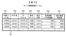
サーバ情報管理テーブル23の構成について、図2を用いて説明する。サーバ情報管理テーブル23は、エントリ毎に、代表ドメイン名231と、ホスト名232と、IPアドレス233と、待受ポート234と、死活状態235と、負荷情報236と、最大接続制限値237とを管理する。 The configuration of the server information management table 23 will be described with reference to FIG. The server information management table 23 includes, for each entry, a
代表ドメイン名231は、クライアント端末10にとってアクセス先となるホスト名である。ホスト名231は、サーバ監視処理部22にとって、サーバ装置30を識別するためのホスト名情報である。IPアドレス233は、サーバ装置30に割り付けられた仮想IPアドレスである。仮想IPアドレスの割り付けは、後述のサーバ遠隔起動処理でDNSサーバ装置が行ってもよいし、システム運用者が手動で割り付けてもよい。 The
クライアント端末10は、この仮想IPアドレス宛てにアクセスする。待受ポート234は、サーバ装置30のサーバプロセスがクライアント端末10からのアクセスを待ち受けているTCPポート番号である。サーバプロセスによっては、UDPポート番号の場合もある。 The
死活状態235は、サーバ装置30がアクティブ(active)状態か、もしくは非アクティブ(inactive)状態か、もしくはスタンバイ(standby)状態か、のいずれかを示す情報である。ここで、DNSサーバ装置20起動時の、サーバ情報管理テーブル23における各エントリの死活状態235の初期状態は、設定ファイルで設定してもよい。例えば、設定ファイルにアクティブ状態のサーバ装置30のリストと、スタンバイ状態のサーバ装置30のリストを設定しておき、DNSサーバ装置20の起動時に、その設定ファイルを読み込み、サーバ情報管理テーブル23に反映しても良い。また、DNSサーバ装置20は、死活情報235がアクティブ(active)もしくは非アクティブ(inactive)となっているエントリを、管理者等が手動でスタンバイ(standby)に変更するためのコマンドを提供しても良い。 The life /
負荷情報236は、サーバ装置30の負荷を表す値である。ここでは、クライアント端末10からサーバ装置30に対して接続されているTCP接続の接続数としている。別の方法としては、CPU使用率などの負荷情報を用いてもよい。最大接続制限値237は、サーバ装置30の許容性能を表す値である。ここでは、クライアント端末10からサーバ装置30に対して接続を許容するTCP接続の(おおよその)接続数としている。この値は、設定値としてDNSサーバ装置20の起動時に与えられている。また、この値は条件に応じて動的に変化させても良い。 The
フリーIPアドレスプール24は、サーバ遠隔起動処理にて、サーバ装置30に仮想IPアドレスとして割り付けるためのIPアドレスを管理するための領域である。ここでは、単純にIPアドレスをリスト形式にて管理している、メモリ上の領域とする。また、その管理、たとえば、増減管理、はシステム運用者がIPアドレスのリストを手動で設定するなどの方法に依ってもよいし、管理機能を備えた専用のシステム管理ソフトウェアで行っても良い。 The free
また、フリーIPアドレスプール24の各エントリは、使用状態フィールドを持つ。使用状態フィールドは、同じIPアドレスを複数のサーバ装置30に重複して割り付けることを防ぐためのフィールドである。サーバ監視処理部22は、使用状態フィールドに、「使用可能(available)」と「使用中(in use)」のどちらかの値を設定する。「使用可能(available)」という値は、あるIPアドレスがサーバ装置30に未割り当ての場合に、そのIPアドレスのエントリの使用状態フィールドに設定される。「使用中(in use)」という値は、あるIPアドレスがサーバ装置30に割り付けられた場合に、そのIPアドレスのエントリの使用状態フィールドに設定される。DNSサーバ装置20は、起動直後に、フリーIPアドレスプール24の全エントリの使用状態フィールドを「使用可能(available)」に初期化する。 Each entry in the free
クライアント端末10と、DNSサーバ装置20と、サーバ装置30と、Sorryサーバ装置40のハードウェア構成の例を図11に示す。 An example of the hardware configuration of the
これらのサーバ装置は、CPU1001、主記憶装置1002、HDD等の外部記憶装置1005、CD-ROMやDVD-ROM等の可搬性を有する記憶媒体1008から情報を読み出す読取装置1003、ディスプレイ、キーボードやマウスなどの入出力装置1006、ネットワーク50に接続するためのNIC(Network Interface Card)等の通信装置1004、及びそれらの装置間を接続するバス等の内部通信線1007を備えた一般的なコンピュータ1000により実現できる。 These server devices include a
例えば、サーバ情報管理テーブル23は、主記憶装置1002の一部の領域を用いて実現する。 For example, the server information management table 23 is realized using a partial area of the
また、DNSサーバ装置20、サーバ装置30、及びSorryサーバ装置40は、それぞれの外部記憶装置1005に記憶されている各種プログラムを主記憶装置1002にロードしてCPU1001で実行し、通信装置1004を用いてネットワーク50に接続してクライアント端末10や他サーバ装置とのネットワーク通信を行うことで、本実施例における各種処理部と、それらによる各種処理を実現する。 Also, the
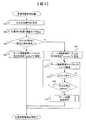
ここで、サーバ監視処理部22が行う死活状態監視処理について、図3を用いて説明する。 Here, the life and death state monitoring process performed by the server
まず、サーバ監視処理部22は、サーバ情報管理テーブル23のIPアドレス233及び待受ポート234及び死活状態235の情報に基づいて、死活状態235が「アクティブ(active)」もしくは「非アクティブ(inactive)」となっている各サーバ装置30の仮想IPアドレス及びポート番号に対して死活状態要求を送信する(ステップS01)。この要求は、例えば、リクエスト行が”GET /health-check.cgi HTTP/1.1”で始まるような、専用のHTTP要求メッセージであっても良いし、ダミーのサービス要求であっても良い。 First, the server
次に、サーバ装置30からの死活状態応答待ち処理を行う(ステップS02)。この時、死活状態応答待ちタイマの設定も行う。 Next, a life / death state response waiting process from the
そして死活状態応答待ちタイマ時間内に死活状態要求に対する応答があるかどうかチェックする(ステップS03)。死活状態要求に対する応答は、例えば、アクティブ状態であれば、レスポンスステータスが”HTTP/1.1 200 OK”となっているようなHTTP応答である。また、非アクティブ状態であれば、それ以外のHTTPエラー応答や無応答である。サーバ装置30から死活状態要求に対する応答があれば、サーバ情報管理テーブル23の死活状態235を「アクティブ(active)」に更新する(ステップS04)。逆に、死活状態の応答がなければ、サーバ情報管理テーブル23の死活状態235を「非アクティブ(inactive)」に更新する(ステップS05)。 Then, it is checked whether there is a response to the life / death state request within the life / death state response waiting timer time (step S03). The response to the alive state request is, for example, an HTTP response whose response status is “HTTP / 1.1 200 OK” in the active state. Further, if it is in an inactive state, there is no other HTTP error response or no response. If there is a response from the
次に、サーバ監視処理部22が行う負荷情報収集処理について、図4を用いて説明する。 Next, load information collection processing performed by the server
まず、サーバ監視処理部22は、サーバ情報管理テーブル23のホスト名232及び死活状態235の情報に基づいて、死活状態235が「アクティブ(active)」となっている各サーバ装置30に対して負荷情報要求を送信する(ステップS11)。この要求は、例えば、独自プロトコルによる要求メッセージである。次に、サーバ装置30からの負荷情報応答待ち処理を行う(ステップS12)。この時、負荷情報応答待ちタイマの設定も行う。 First, the server
そして負荷情報応答待ちタイマ時間内に負荷情報の応答があるかどうかチェックする(ステップS13)。負荷情報の応答は、例えば、独自プロトコルによる応答メッセージであり、サーバ装置30が受信しているHTTP接続数の数などが記載されている。サーバ装置30から負荷情報の応答があれば、サーバ情報管理テーブル23の負荷情報236を、応答メッセージに記載されていたHTTP接続数の値に更新する(ステップS14)。逆に、負荷状態の応答がなければ、サーバ情報管理テーブル23の負荷情報236を「非アクティブ(inactive)」に更新し、負荷情報236を”0”に更新する(ステップS15)。 Then, it is checked whether or not there is a load information response within the load information response waiting timer time (step S13). The load information response is, for example, a response message based on a unique protocol, and describes the number of HTTP connections received by the
次に、DNSサーバ処理部21が行うDNSサーバ処理の一例について、図5を用いて説明する。 Next, an example of DNS server processing performed by the DNS
まず、クライアント端末10から名前解決要求を受信するまで待機する(ステップS21)。 First, it waits until a name resolution request is received from the client terminal 10 (step S21).
名前解決要求を受信すると、名前解決要求対象の代表ドメイン名を検索キーとしてサーバ情報管理テーブル23を検索し、代表ドメイン名231が名前解決要求対象の代表ドメイン名と一致するエントリ情報を取得する(ステップS22)。 When the name resolution request is received, the server information management table 23 is searched using the representative domain name of the name resolution request target as a search key, and entry information whose
ここで、処理の一例として、サーバ情報管理テーブル23の先頭エントリから末尾エントリに向かって、一つずつ順番にエントリ情報を取得してもよい。 Here, as an example of processing, the entry information may be acquired one by one in order from the first entry to the last entry of the server information management table 23.
ステップS22でエントリ情報が取得できたならばステップS24に進む。取得できなければステップS27に進む(ステップS23)。ここで、取得できない場合とは、即ち、全エントリの検索が終了した場合である。 If the entry information can be acquired in step S22, the process proceeds to step S24. If not acquired, the process proceeds to step S27 (step S23). Here, the case where acquisition is not possible means that the search of all entries is completed.
取得したエントリ情報の死活状態235が「アクティブ(active)」かどうかチェックする(ステップS24)。「アクティブ(active)」であればステップS25に進む。それ以外であればステップS22に戻り、次のエントリ情報を取得する。 It is checked whether the life and
ステップS25において、負荷情報236の値が最大接続制限値237以下かどうかチェックする。以下であればステップS26に進む。そうでなければステップS22に戻り、次のエントリ情報を取得する。 In step S25, it is checked whether the value of the
ステップS26において、DNSサーバ処理部21は、当該エントリのIPアドレス233の値をクライアント端末10に応答し、DNSサーバ処理を終了する。 In step S26, the DNS
ステップS23で、エントリ情報が取得できなければ、Sorryサーバ装置40のIPアドレスを応答する(ステップS27)。ここで、Sorryサーバ装置40のIPアドレスを、DNSサーバ装置20の外部記憶装置1005の中の設定ファイルに予め記述しておいて、DNSサーバ装置20は起動時にその設定ファイルを読み取って主記憶装置1002に保持しておき、ステップS27において、そのIPアドレスを応答しても良い。 If the entry information cannot be acquired in step S23, the IP address of the sorry server device 40 is returned (step S27). Here, the IP address of the sorry server device 40 is described in advance in a setting file in the
次に、DNSサーバ処理部21が行うDNSサーバ処理の別の一例について、図6を用いて説明する。この例では、ステップS21ないしステップS27の処理内容については、図5での例と同じである。 Next, another example of the DNS server process performed by the DNS
ここで、ステップS23において、エントリ情報が取得できたならばステップS24に進み、図5と同様の処理を行う。取得できなければステップS31に進み、ステップS31〜S33において、死活状態が「スタンバイ(standby)」のエントリを探す。具体的な処理は、以下の通り。 If entry information can be acquired in step S23, the process proceeds to step S24, and the same processing as in FIG. 5 is performed. If not acquired, the process proceeds to step S31. In steps S31 to S33, an entry whose life and death state is “standby” is searched. Specific processing is as follows.
サーバ情報管理テーブル23から任意のエントリ情報を取得する(ステップS31)。ここで、処理の一例として、サーバ情報管理テーブル23の先頭エントリから末尾エントリに向かって、一つずつ順番にエントリ情報を取得してもよい。 Arbitrary entry information is acquired from the server information management table 23 (step S31). Here, as an example of processing, the entry information may be acquired one by one in order from the first entry to the last entry of the server information management table 23.
次に、ステップS31でエントリ情報が取得できたならばステップS33に進む。取得できなければステップS27に進む(ステップS32)。ここで、取得できない場合とは、即ち、全エントリの検索が終了したが、死活状態が「スタンバイ(standby)」のエントリが無かった場合である。 Next, if entry information can be acquired in step S31, the process proceeds to step S33. If not acquired, the process proceeds to step S27 (step S32). Here, the case where acquisition is not possible means that all entries have been searched, but there is no entry whose life-and-death state is “standby”.
取得したエントリ情報の死活状態235が「スタンバイ(standby)」かどうかをチェックする(ステップS33)。「スタンバイ(standby)」であればステップS34に進む。それ以外であればステップS31に戻り、次のエントリ情報を取得する。 It is checked whether the life and
ステップS34では、サーバ遠隔起動処理を行う(詳細な処理内容は後述する)。 In step S34, server remote activation processing is performed (detailed processing content will be described later).
ステップS34において、サーバ遠隔起動処理が成功したならばステップS26に進む。失敗したならばステップS27に進む(ステップS35)。 If the server remote activation process is successful in step S34, the process proceeds to step S26. If unsuccessful, the process proceeds to step S27 (step S35).
ここで、DNSサーバ装置20のサーバ監視処理部22が行うステップS34のサーバ遠隔起動処理の処理内容の一例について、図7を用いて説明する。 Here, an example of the processing contents of the server remote activation processing in step S34 performed by the server
当該サーバ遠隔起動処理は、サーバ監視処理部22が、サーバ情報管理テーブル23の死活状態235の情報が「スタンバイ(standby)」になっているサーバ装置30のいずれかに対し、新しくサーバ装置を起動する命令を発行する処理である。 In the server remote activation processing, the server
まず、サーバ監視処理部22は、フリーIPアドレスプール24に、使用状態フィールドの値が「使用可能(available)」となっているIPアドレスが1個以上プールされているかをチェックする(ステップS41)。一つ以上の「使用可能(available)」状態のIPアドレスがあれば(S41でY)、サーバ情報管理テーブル23の死活状態235の情報が「スタンバイ(standby)」になっているいずれかのサーバ装置30のサーバ起動処理部33に対し、サーバ装置30のサーバ起動処理部33に対し、サーバ起動命令およびIPアドレスの値を送信し、フリーIPアドレスプール24における、送信したIPアドレスのエントリの使用状態フィールドを「使用中(in use)」に変更する(ステップS42)。 First, the
なお、スタンバイ状態のサーバ装置30が複数ある場合のサーバ装置30の選択方法の一例として、サーバ情報管理テーブル23において、死活状態235の情報が「スタンバイ(standby)」となっているエントリのうち、テーブルの先頭に最も近いエントリを選択する、という方法でもよい。 As an example of a method of selecting the
その後、サーバ装置30に対する起動確認応答待ち処理を行う(ステップS43)。この時、起動確認応答待ちタイマの設定も行う。そして、起動確認応答待ちタイマ時間内に起動確認応答があるかどうかチェックする(ステップS44)。 After that, a startup confirmation response waiting process for the
起動確認応答があれば(S44でY)処理成功とみなし、死活状態235の情報を「スタンバイ(standby)」から「アクティブ(active)」に変更し、本処理を終了する(ステップS45)。また、ステップS41でIPアドレスが無かった場合(S41でN)や、ステップS44でタイマ時間内に起動確認応答が無かった場合(S44でN)は処理失敗とみなし、システムログにエラーメッセージを出力し、本処理を終了する(ステップS46)。 If there is an activation confirmation response (Y in S44), it is considered that the process is successful, the information on the life /
次に、サーバ装置30は、クライアント端末10に対し、WebサービスやProxyサービスを提供するサーバプロセスが稼働する装置である。サーバ装置30は、HTTPサーバ処理部31と、負荷情報応答処理部32と、サーバ起動処理部33とを備える。HTTPサーバ処理部31は、クライアント端末10からHTTP要求を受信すると、HTTPサーバ処理を行う。負荷情報応答処理部32は、DNSサーバ装置20のサーバ監視処理部22からの負荷情報収集要求に対して、仮想IPアドレス毎に、クライアント端末10から接続されているTCP接続の接続数を応答する。別の方法としては、サーバ装置30のCPU使用率などの負荷情報を用いてもよい。サーバ起動処理部33は、DNSサーバ装置20からのサーバ起動命令に対し、サーバ起動処理を行う。 Next, the
ここで、サーバ装置30のサーバ起動処理部33が行うサーバ起動処理について、図8を用いて説明する。 Here, the server activation processing performed by the server
まず、サーバ起動処理部33は、DNSサーバ装置20のサーバ監視処理部22から、ステップS32にてサーバ起動命令およびIPアドレスが送信されるのを待ち受ける(ステップS51)。受信すると、HTTPサーバ処理部31を備えるサーバアプリケーションを起動する(ステップS52)。ここで、起動するサーバは、仮想マシン上で動作する仮想サーバでも良い。そして、サーバ起動後、ステップS51で受信したIPアドレスを、仮想IPアドレスとしてネットワークインタフェースに設定する(ステップS53)。最後に、DNSサーバ装置20に起動の確認応答を送信する(ステップS54)。 First, the server
次に、サーバ監視処理部22が行う死活状態監視処理の別の一例について、図9を用いて説明する。この例では、ステップS01ないしステップS05の処理内容については、図3での例と同じである。また、ステップS31ないしステップS34の処理内容については、図6での例と同じである。 Next, another example of the life and death state monitoring process performed by the server
ステップS05で、死活状態235を「非アクティブ(inactive)」に変更後、サーバ遠隔起動処理を行い、スタンバイサーバを起動する。具体的には、ステップS05の処理を行った後、ステップS31の処理を行い、ステップS32に進み、エントリ情報を取得できれば、ステップS34のサーバ遠隔起動処理を行い、その後、死活状態監視処理を終了する。ステップS32において、エントリ情報を取得できなければ、単に死活状態監視処理を終了する。 In step S05, after changing the life /
次に、サーバ監視処理部22が行う負荷情報収集処理の別の一例について、図10を用いて説明する。この例では、ステップS11ないしステップS15の処理内容については、図4での例と同じである。また、ステップS31ないしステップS34の処理内容については、図6での例と同じである。 Next, another example of the load information collection process performed by the
ステップS15で、死活状態235を「非アクティブ(inactive)」に変更後、サーバ遠隔起動処理を行い、スタンバイサーバを起動する。具体的には、ステップS15の処理を行った後、ステップS31の処理を行い、ステップS32に進み、エントリ情報を取得できれば、ステップS34のサーバ遠隔起動処理を行い、その後、負荷情報収集処理を終了する。ステップS32において、エントリ情報を取得できなければ、単に負荷情報収集処理を終了する。 In step S15, after changing the
なお、本発明は、上記実施形態に限定されず、種々の変形や応用が可能である。 In addition, this invention is not limited to the said embodiment, A various deformation | transformation and application are possible.
10:クライアント端末
20:DNSサーバ装置
21:DNSサーバ処理部
22:サーバ監視処理部
23:サーバ情報管理テーブル
24:フリーIPアドレスプール
30:サーバ装置
31:HTTPサーバ処理部
32:負荷情報応答処理部
33:サーバ起動処理部
40:Sorryサーバ装置
41:Sorryサーバ処理部
50:ネットワーク
231:代表ドメイン名
232:ホスト名
233:IPアドレス
234:待受ポート
235:死活状態
236:負荷情報
237:最大接続制限値
1000:コンピュータ
1001:CPU
1002:主記憶装置
1003:読取装置
1004:通信装置
1005:外部記憶装置
1006:入出力装置
1007:内部通信線
1008:可搬記憶媒体10: Client terminal 20: DNS server device 21: DNS server processing unit 22: Server monitoring processing unit 23: Server information management table 24: Free IP address pool 30: Server device 31: HTTP server processing unit 32: Load information response processing unit 33: Server activation processing unit 40: Sorry server device 41: Sorry server processing unit 50: Network 231: Representative domain name 232: Host name 233: IP address 234: Standby port 235: Life / death state 236: Load information 237: Maximum connection Limit value 1000: Computer 1001: CPU
1002: Main storage device 1003: Reading device 1004: Communication device 1005: External storage device 1006: Input / output device 1007: Internal communication line 1008: Portable storage medium
Claims (9)
Translated fromJapanese前記DNSサーバ装置は、前記クライアント端末から名前解決要求を受信すると、前記クライアント端末に対して、前記名前解決処理を行い、該当するいずれかの前記サービス提供サーバ装置のIPアドレスを応答するDNSサーバ処理を行い、
前記一つ以上のサービス提供サーバ装置は、前記クライアント端末に対し、WebサービスやProxyサービスを提供し、
前記Sorryサーバ装置は、前記クライアント端末からHTTPアクセスを受信すると、要求されたサービスを提供できない旨を示すメッセージを応答し、
前記DNSサーバ装置は、
前記サービス提供サーバ装置のアクティブ/非アクティブ状態の監視、及び負荷情報の収集を、繰り返し行い、
前記名前解決処理の結果、前記該当するサービス提供サーバ装置が、アクティブだが輻輳している場合、もしくは、非アクティブの場合に、前記Sorryサーバに割り付けられたIPアドレスを前記クライアント端末に応答する
ことを特徴とするネットワークシステム。A network system in which a domain name system (DNS) server device, one or more service providing server devices, and a sorry server device are connected via a network and provide services to client terminals via the network,
When the DNS server apparatus receives a name resolution request from the client terminal, the DNS server process performs the name resolution process on the client terminal and responds with an IP address of any corresponding service providing server apparatus And
The one or more service providing server devices provide a Web service or a Proxy service to the client terminal;
When receiving the HTTP access from the client terminal, the sorry server device responds with a message indicating that the requested service cannot be provided,
The DNS server device
Monitoring the active / inactive state of the service providing server device and collecting load information repeatedly,
As a result of the name resolution processing, when the corresponding service providing server device is active but congested or inactive, it responds to the client terminal with the IP address assigned to the sorry server. A characteristic network system.
前記DNSサーバ装置は、
前記サービス提供サーバ装置の代表ドメイン名ごとの情報を管理するサーバ情報管理テーブルを備え、
前記サービス提供サーバ装置の死活状態監視処理と負荷情報収集処理とを繰り返し行うサーバ監視処理を行い、
前記サーバ監視処理結果を前記サーバ情報管理テーブルに記録し、
前記サービス提供サーバ装置は、前記DNSサーバ装置からの負荷情報収集要求に対して、自サーバに設定されている仮想IPアドレス毎に、前記クライアント端末から接続されているTCP接続の接続数を応答する負荷情報応答処理を行う
ことを特徴とするネットワークシステム。The network system according to claim 1,
The DNS server device
A server information management table for managing information for each representative domain name of the service providing server device;
A server monitoring process for repeatedly performing the alive state monitoring process and the load information collecting process of the service providing server device,
Record the server monitoring processing result in the server information management table;
In response to the load information collection request from the DNS server device, the service providing server device responds with the number of TCP connections connected from the client terminal for each virtual IP address set in the server itself. A network system characterized by performing load information response processing.
前記サーバ情報管理テーブルは、エントリ毎に、IPアドレスフィールドと、待受ポートフィールドと、死活状態フィールドと、を備え、
前記IPアドレスフィールドは、前記サービス提供サーバ装置に仮想IPアドレスとして割り付けられたIPアドレスを管理するフィールドであり、
前記待受ポートフィールドは、前記サービス提供サーバ装置が前記クライアント端末からのアクセスを待ち受けているTCPもしくはUDPポート番号を格納するフィールドであり、
前記死活状態フィールドは、前記サービス提供サーバ装置がアクティブ状態か、もしくは非アクティブ状態か、もしくはスタンバイ状態か、を示す情報を格納するフィールドであり、
前記DNSサーバ装置は、前記死活状態監視処理において、
前記サーバ情報管理テーブルの前記IPアドレスフィールド及び前記待受ポートフィールド及び前記死活状態フィールドの情報に基づいて、前記死活状態フィールドの値が「アクティブ」もしくは「非アクティブ」となっている前記サービス提供サーバ装置の仮想IPアドレス及びポート番号に対して死活状態要求を送信し、
タイマ監視しながら、前記サービス提供サーバ装置から、前記死活状態要求への応答待ち処理を行い、
タイマ時間内に、前記サービス提供サーバ装置から前記死活状態要求への応答があれば、前記サーバ情報管理テーブルの前記死活状態フィールドを「アクティブ」に更新し、前記応答がなければ、前記死活状態フィールドを「非アクティブ」に更新する
ことを特徴とするネットワークシステム。The network system according to claim 2,
The server information management table includes, for each entry, an IP address field, a standby port field, and an alive state field,
The IP address field is a field for managing an IP address assigned as a virtual IP address to the service providing server device,
The standby port field is a field for storing a TCP or UDP port number on which the service providing server device is waiting for access from the client terminal,
The life and death state field is a field for storing information indicating whether the service providing server device is in an active state, an inactive state, or a standby state,
In the life and death state monitoring process, the DNS server device
The service providing server in which the value of the alive state field is “active” or “inactive” based on the information of the IP address field, the standby port field, and the alive state field of the server information management table Send a alive request to the virtual IP address and port number of the device,
While monitoring the timer, from the service providing server device, waits for a response to the alive state request,
If there is a response from the service providing server device to the alive state request within the timer time, the alive state field of the server information management table is updated to “active”, and if there is no response, the alive state field A network system characterized in that the system is updated to “inactive”.
前記サーバ情報管理テーブルは、エントリ毎に、ホスト名フィールドと、負荷情報フィールドと、を備え、
前記ホスト名フィールドは、前記サーバ監視処理手段にとって、前記サービス提供サーバ装置を識別するためのホスト名情報を格納するフィールドであり、
前記負荷情報フィールドは、前記サービス提供サーバ装置の負荷を表す値として、前記クライアント端末から前記サービス提供サーバ装置に対して接続されているTCP接続の接続数を格納するフィールドであり、
前記DNSサーバ装置は、前記負荷情報収集処理において、
前記サーバ情報管理テーブルの前記ホスト名フィールド及び前記死活状態フィールドの情報に基づいて、前記死活状態フィールドの値が「アクティブ」となっている前記サービス提供サーバ装置に対して前記負荷情報要求を送信し、
タイマ監視しながら、前記サービス提供サーバ装置から、前記負荷情報要求への応答待ち処理を行い、
タイマ時間内に、前記サービス提供サーバ装置から前記負荷情報要求への応答があれば、前記サーバ情報管理テーブルの前記負荷情報フィールドを、前記応答に含まれているHTTP接続数の値に更新し、前記応答がなければ、前記死活状態フィールドを「非アクティブ」に更新する
ことを特徴とするネットワークシステム。The network system according to claim 3,
The server information management table includes a host name field and a load information field for each entry.
The host name field is a field for storing host name information for identifying the service providing server device for the server monitoring processing means,
The load information field is a field for storing the number of TCP connections connected from the client terminal to the service providing server device as a value representing the load of the service providing server device,
In the load information collection process, the DNS server device
Based on the information of the host name field and the alive state field of the server information management table, the load information request is transmitted to the service providing server device whose value of the alive state field is “active”. ,
While monitoring the timer, from the service providing server device, waits for a response to the load information request,
If there is a response to the load information request from the service providing server device within the timer time, the load information field of the server information management table is updated to the value of the number of HTTP connections included in the response, If there is no response, the alive state field is updated to “inactive”.
前記サーバ情報管理テーブルは、エントリ毎に、代表ドメイン名フィールドと、最大接続制限値フィールドと、を備え、
前記代表ドメイン名フィールドは、前記クライアント端末にとってアクセス先となるホスト名を格納するフィールドであり、
前記最大接続制限値フィールドは、前記サービス提供サーバ装置の許容性能を表す値として、前記クライアント端末から前記サービス提供サーバ装置に対して接続を許容するTCPもしくはUDP接続数を格納するフィールドであり、
前記DNSサーバ装置は、前記DNSサーバ処理として、
前記名前解決要求を受信すると、名前解決要求対象の代表ドメイン名に基づいて、前記サーバ情報管理テーブルの前記代表ドメイン名フィールドを検索し、
前記検索にヒットしたエントリの前記死活状態フィールドが「アクティブ」であり、かつ、前記負荷情報フィールドの値が前記最大接続制限値フィールドの値以下であれば、当該エントリの前記IPアドレスフィールドの値を前記クライアント端末に応答し、
前記死活状態フィールドが「アクティブ」以外であるか、もしくは、前記負荷情報フィールドの値が前記最大接続制限値フィールドの値以上の場合に、前記代表ドメイン名フィールドの値が同じである他エントリがあれば、当該エントリの前記死活状態フィールドが「アクティブ」かどうかチェックし、
前記他エントリがなければ、前記SorryサーバのIPアドレスを応答する
ことを特徴とするネットワークシステム。The network system according to claim 4, wherein
The server information management table includes a representative domain name field and a maximum connection limit value field for each entry,
The representative domain name field is a field for storing a host name to be accessed for the client terminal,
The maximum connection limit value field is a field for storing the number of TCP or UDP connections that allow connection from the client terminal to the service providing server device as a value representing the allowable performance of the service providing server device,
The DNS server apparatus performs the DNS server process as follows:
When the name resolution request is received, the representative domain name field of the server information management table is searched based on the representative domain name of the name resolution request target,
If the alive state field of the entry hit in the search is “active” and the value of the load information field is less than or equal to the value of the maximum connection limit value field, the value of the IP address field of the entry is changed. In response to the client terminal;
If the alive state field is other than “active”, or if the value of the load information field is equal to or greater than the value of the maximum connection limit value field, there may be other entries with the same value of the representative domain name field. For example, check whether the alive state field of the entry is “active”
If there is no other entry, the network system responds with the IP address of the sorry server.
前記DNSサーバ装置は、
スタンバイ状態になっているサービス提供サーバ装置に対し、起動命令を発行するサーバ遠隔起動処理を行う、
ことを特徴とするネットワークシステム。The network system according to claim 5,
The DNS server device
Server remote start processing that issues a start command to the service providing server device in the standby state.
A network system characterized by this.
前記DNSサーバ装置は、前記サービス提供サーバ装置に割り付けるためのIPアドレスを管理するためのメモリ上の領域であるフリーIPアドレスプールを備え、
前記サーバ遠隔起動処理は、
前記フリーIPアドレスプールにIPアドレスが1個以上プールされていれば、前記サーバ情報管理テーブルの前記死活状態フィールドの値が「スタンバイ」になっているエントリの前記ホスト名フィールドが示す前記サービス提供サーバ装置に対し、サーバ起動命令およびIPアドレスを送信して起動を命令し、
前記サーバ起動命令に対する起動確認応答処理を、タイマ監視しながら行い、
タイマ時間内に起動確認応答があれば、前記死活状態フィールドの値を「スタンバイ」から「アクティブ」に変更して、前記サーバ遠隔起動処理を終了し、
プールされている前記IPアドレスが無かった場合、または、タイマ時間内にスタンバイ状態になっている前記サービス提供サーバ装置から起動確認応答が無かった場合に、システムログにエラーメッセージを出力し、前記サーバ遠隔起動処理を終了する処理であり、
スタンバイ状態になっている前記サービス提供サーバ装置は、前記DNSサーバ装置から、サーバ起動命令およびIPアドレスが送信されるのを待ち、
サーバ起動命令およびIPアドレス受信すると、HTTPサーバ処理手段を起動し、
IPアドレスを、仮想IPアドレスとしてネットワークインタフェースに設定し、
前記DNSサーバ装置に起動の確認応答を送信する
ことを特徴とするネットワークシステム。The network system according to claim 6, wherein
The DNS server device includes a free IP address pool that is an area on a memory for managing an IP address to be allocated to the service providing server device,
The server remote activation process includes:
If at least one IP address is pooled in the free IP address pool, the service providing server indicated by the host name field of the entry whose value of the life / death state field of the server information management table is “standby” Instruct the device to start by sending a server start command and IP address,
The start confirmation response process for the server start command is performed while monitoring the timer,
If there is a start confirmation response within the timer time, the value of the alive state field is changed from “standby” to “active”, and the server remote start processing is terminated,
When there is no pooled IP address, or when there is no activation confirmation response from the service providing server device that is in a standby state within a timer time, an error message is output to the system log, and the server It is a process that ends the remote startup process,
The service providing server device in a standby state waits for a server start command and an IP address to be transmitted from the DNS server device,
When the server activation command and the IP address are received, the HTTP server processing means is activated,
Set the IP address to the network interface as a virtual IP address,
A network system, wherein an activation confirmation response is transmitted to the DNS server device.
前記サーバ遠隔起動処理の発動条件が、
いずれかの前記サービス提供サーバ装置が過負荷状態になった場合、
であることを特徴とするネットワークシステム。The network system according to claim 6 or 7, wherein
The activation condition of the server remote activation process is
If any of the service providing server devices is overloaded,
A network system characterized by
前記サーバ遠隔起動処理の発動条件が、
いずれかの前記サービス提供サーバ装置が「非アクティブ」になった場合、
であることを特徴とするネットワークシステム。The network system according to claim 6 or 7, wherein
The activation condition of the server remote activation process is
When any one of the service providing server devices becomes “inactive”,
A network system characterized by
Priority Applications (3)
| Application Number | Priority Date | Filing Date | Title |
|---|---|---|---|
| JP2010236982AJP5557689B2 (en) | 2010-10-22 | 2010-10-22 | Network system |
| US13/216,112US8543692B2 (en) | 2010-10-22 | 2011-08-23 | Network system |
| EP20110178581EP2445173A2 (en) | 2010-10-22 | 2011-08-24 | Network system |
Applications Claiming Priority (1)
| Application Number | Priority Date | Filing Date | Title |
|---|---|---|---|
| JP2010236982AJP5557689B2 (en) | 2010-10-22 | 2010-10-22 | Network system |
Publications (2)
| Publication Number | Publication Date |
|---|---|
| JP2012090194Atrue JP2012090194A (en) | 2012-05-10 |
| JP5557689B2 JP5557689B2 (en) | 2014-07-23 |
Family
ID=44534006
Family Applications (1)
| Application Number | Title | Priority Date | Filing Date |
|---|---|---|---|
| JP2010236982AExpired - Fee RelatedJP5557689B2 (en) | 2010-10-22 | 2010-10-22 | Network system |
Country Status (3)
| Country | Link |
|---|---|
| US (1) | US8543692B2 (en) |
| EP (1) | EP2445173A2 (en) |
| JP (1) | JP5557689B2 (en) |
Cited By (6)
| Publication number | Priority date | Publication date | Assignee | Title |
|---|---|---|---|---|
| JP2013098880A (en)* | 2011-11-04 | 2013-05-20 | Hitachi Ltd | Filtering system and filtering method |
| US9071612B2 (en) | 2011-10-17 | 2015-06-30 | Hitachi, Ltd. | Service providing system |
| CN110995542A (en)* | 2019-12-16 | 2020-04-10 | 金蝶智慧科技(深圳)有限公司 | Network state detection method, system and related equipment |
| US11190583B2 (en) | 2018-03-23 | 2021-11-30 | Nec Corporation | Load balancing device, communication system, control method, and program |
| JP2022046436A (en)* | 2020-09-10 | 2022-03-23 | フィッシャー-ローズマウント システムズ,インコーポレイテッド | Node management of node communication networks for versatile field devices in control and automation systems |
| WO2022190387A1 (en)* | 2021-03-12 | 2022-09-15 | 楽天モバイル株式会社 | Management system and management method |
Families Citing this family (12)
| Publication number | Priority date | Publication date | Assignee | Title |
|---|---|---|---|---|
| JP2012018515A (en)* | 2010-07-07 | 2012-01-26 | Fujitsu Ltd | Information processor, control method, and control program |
| WO2013155685A1 (en)* | 2012-04-18 | 2013-10-24 | Renesas Mobile Corporation | Mobile data collection in a wireless sensing network |
| CN103428310B (en)* | 2013-08-15 | 2016-08-24 | 网宿科技股份有限公司 | Non-HTTP domain name based on virtual IP address guides system and method |
| US9923959B2 (en) | 2014-06-05 | 2018-03-20 | Microsoft Technology Licensing, Llc | Load balancing with layered edge servers |
| US9400654B2 (en)* | 2014-06-27 | 2016-07-26 | Freescale Semiconductor, Inc. | System on a chip with managing processor and method therefor |
| GB2546800B (en)* | 2016-01-29 | 2020-08-05 | Tectonic Interactive Ltd | System and method for managing communication sessions between clients and a server |
| US11223515B2 (en)* | 2017-09-06 | 2022-01-11 | Nec Corporation | Cluster system, cluster system control method, server device, control method, and non-transitory computer-readable medium storing program |
| US10608942B1 (en)* | 2017-11-30 | 2020-03-31 | Amazon Technologies, Inc. | Reducing routes based on network traffic utilization |
| US11245750B2 (en)* | 2019-02-16 | 2022-02-08 | International Business Machines Corporation | File server load balancing |
| US11063882B2 (en)* | 2019-08-07 | 2021-07-13 | International Business Machines Corporation | Resource allocation for data integration |
| CN110995890B (en)* | 2020-03-03 | 2020-10-16 | 北京安博通科技股份有限公司 | Domain name request scheduling method and device |
| US11196665B1 (en)* | 2020-11-12 | 2021-12-07 | Sap Se | Routing application calls |
Citations (4)
| Publication number | Priority date | Publication date | Assignee | Title |
|---|---|---|---|---|
| JP2000196677A (en)* | 1998-12-28 | 2000-07-14 | Fujitsu Ltd | Relay device used in network system |
| JP2002111713A (en)* | 2000-09-28 | 2002-04-12 | Toshiba Corp | Network system, name server, server, and IP communication method for network system |
| JP2006222631A (en)* | 2005-02-09 | 2006-08-24 | Hitachi Ltd | Congestion control device and network congestion control method |
| JP2009017182A (en)* | 2007-07-04 | 2009-01-22 | Toppan Printing Co Ltd | Load distribution apparatus and load distribution method |
Family Cites Families (5)
| Publication number | Priority date | Publication date | Assignee | Title |
|---|---|---|---|---|
| US7373500B2 (en)* | 2003-04-15 | 2008-05-13 | Sun Microsystems, Inc. | Secure network processing |
| JP2008104027A (en)* | 2006-10-19 | 2008-05-01 | Fujitsu Ltd | Packet information collecting apparatus and packet information collecting program |
| US20080291916A1 (en)* | 2007-05-22 | 2008-11-27 | Bo Xiong | Systems and methods for dynamic quality of service |
| JP5074290B2 (en)* | 2008-05-13 | 2012-11-14 | 株式会社日立国際電気 | Redundancy switching system, redundancy management device and application processing device |
| CN102648634A (en)* | 2009-12-07 | 2012-08-22 | 松下电器产业株式会社 | Format conversion server, playback device, and information playback system |
- 2010
- 2010-10-22JPJP2010236982Apatent/JP5557689B2/ennot_activeExpired - Fee Related
- 2011
- 2011-08-23USUS13/216,112patent/US8543692B2/ennot_activeExpired - Fee Related
- 2011-08-24EPEP20110178581patent/EP2445173A2/ennot_activeWithdrawn
Patent Citations (4)
| Publication number | Priority date | Publication date | Assignee | Title |
|---|---|---|---|---|
| JP2000196677A (en)* | 1998-12-28 | 2000-07-14 | Fujitsu Ltd | Relay device used in network system |
| JP2002111713A (en)* | 2000-09-28 | 2002-04-12 | Toshiba Corp | Network system, name server, server, and IP communication method for network system |
| JP2006222631A (en)* | 2005-02-09 | 2006-08-24 | Hitachi Ltd | Congestion control device and network congestion control method |
| JP2009017182A (en)* | 2007-07-04 | 2009-01-22 | Toppan Printing Co Ltd | Load distribution apparatus and load distribution method |
Cited By (8)
| Publication number | Priority date | Publication date | Assignee | Title |
|---|---|---|---|---|
| US9071612B2 (en) | 2011-10-17 | 2015-06-30 | Hitachi, Ltd. | Service providing system |
| JP2013098880A (en)* | 2011-11-04 | 2013-05-20 | Hitachi Ltd | Filtering system and filtering method |
| US11190583B2 (en) | 2018-03-23 | 2021-11-30 | Nec Corporation | Load balancing device, communication system, control method, and program |
| CN110995542A (en)* | 2019-12-16 | 2020-04-10 | 金蝶智慧科技(深圳)有限公司 | Network state detection method, system and related equipment |
| CN110995542B (en)* | 2019-12-16 | 2022-04-22 | 金蝶智慧科技(深圳)有限公司 | Network state detection method, system and related equipment |
| JP2022046436A (en)* | 2020-09-10 | 2022-03-23 | フィッシャー-ローズマウント システムズ,インコーポレイテッド | Node management of node communication networks for versatile field devices in control and automation systems |
| JP7718917B2 (en) | 2020-09-10 | 2025-08-05 | フィッシャー-ローズマウント システムズ,インコーポレイテッド | Node management of node communication networks for highly versatile field devices in control and automation systems |
| WO2022190387A1 (en)* | 2021-03-12 | 2022-09-15 | 楽天モバイル株式会社 | Management system and management method |
Also Published As
| Publication number | Publication date |
|---|---|
| JP5557689B2 (en) | 2014-07-23 |
| US8543692B2 (en) | 2013-09-24 |
| US20120102192A1 (en) | 2012-04-26 |
| EP2445173A2 (en) | 2012-04-25 |
Similar Documents
| Publication | Publication Date | Title |
|---|---|---|
| JP5557689B2 (en) | Network system | |
| JP3980596B2 (en) | Method and system for remotely and dynamically configuring a server | |
| KR100830413B1 (en) | Server access system for clients and load balancing network system including the same | |
| JP5582344B2 (en) | Connection management system and connection management server linkage method in thin client system | |
| US20110087783A1 (en) | Allocating resources of a node in a server farm | |
| JP4311636B2 (en) | A computer system that shares a storage device among multiple computers | |
| CN113760447B (en) | Service management method, device, equipment, storage medium and program product | |
| CN111212134A (en) | Request message processing method and device, edge computing system and electronic equipment | |
| JP2003248611A (en) | Storage management integrated system and storage management control method thereof | |
| JP5724687B2 (en) | Information processing apparatus, server selection method, and program | |
| US7490140B2 (en) | Peer data transfer orchestration | |
| JP6272190B2 (en) | Computer system, computer, load balancing method and program thereof | |
| US9390156B2 (en) | Distributed directory environment using clustered LDAP servers | |
| CN113014611A (en) | Load balancing method and related equipment | |
| WO2023207189A1 (en) | Load balancing method and system, computer storage medium, and electronic device | |
| JP2016526723A (en) | Managing client access to multiple computing systems | |
| JP5749812B2 (en) | DNS proxy service for multi-core platforms | |
| JP5287623B2 (en) | Virtual server management system, image processing system, virtual server management apparatus, and control program | |
| JPWO2009034994A1 (en) | Load distribution system, service processing server, load distribution method, and load distribution program | |
| JP2005010983A (en) | Server load balancing method, load balancing system, load balancing device and server used in the system | |
| CN111711569A (en) | System and method for realizing request dynamic routing in enterprise distributed application | |
| JP2010039661A (en) | Server load distribution device, method, and program | |
| JP2015111330A (en) | Terminal device, communication system, and communication program | |
| JP5691248B2 (en) | Task takeover program, processing device, and computer system | |
| JP2002049602A (en) | Search system |
Legal Events
| Date | Code | Title | Description |
|---|---|---|---|
| RD04 | Notification of resignation of power of attorney | Free format text:JAPANESE INTERMEDIATE CODE: A7424 Effective date:20120521 | |
| A621 | Written request for application examination | Free format text:JAPANESE INTERMEDIATE CODE: A621 Effective date:20130208 | |
| A977 | Report on retrieval | Free format text:JAPANESE INTERMEDIATE CODE: A971007 Effective date:20131115 | |
| A131 | Notification of reasons for refusal | Free format text:JAPANESE INTERMEDIATE CODE: A131 Effective date:20131126 | |
| A521 | Request for written amendment filed | Free format text:JAPANESE INTERMEDIATE CODE: A523 Effective date:20140127 | |
| A131 | Notification of reasons for refusal | Free format text:JAPANESE INTERMEDIATE CODE: A131 Effective date:20140304 | |
| A521 | Request for written amendment filed | Free format text:JAPANESE INTERMEDIATE CODE: A523 Effective date:20140414 | |
| TRDD | Decision of grant or rejection written | ||
| A01 | Written decision to grant a patent or to grant a registration (utility model) | Free format text:JAPANESE INTERMEDIATE CODE: A01 Effective date:20140507 | |
| A61 | First payment of annual fees (during grant procedure) | Free format text:JAPANESE INTERMEDIATE CODE: A61 Effective date:20140603 | |
| LAPS | Cancellation because of no payment of annual fees |