JP2012089906A - Display controller - Google Patents
Display controllerDownload PDFInfo
- Publication number
- JP2012089906A JP2012089906AJP2009101822AJP2009101822AJP2012089906AJP 2012089906 AJP2012089906 AJP 2012089906AJP 2009101822 AJP2009101822 AJP 2009101822AJP 2009101822 AJP2009101822 AJP 2009101822AJP 2012089906 AJP2012089906 AJP 2012089906A
- Authority
- JP
- Japan
- Prior art keywords
- stereoscopic video
- image
- video
- stereoscopic
- information
- Prior art date
- Legal status (The legal status is an assumption and is not a legal conclusion. Google has not performed a legal analysis and makes no representation as to the accuracy of the status listed.)
- Pending
Links
Images


Landscapes
- Controls And Circuits For Display Device (AREA)
- Testing, Inspecting, Measuring Of Stereoscopic Televisions And Televisions (AREA)
Abstract
Translated fromJapaneseDescription
Translated fromJapanese本発明は、立体映像を表示させる表示制御装置に関する。特に、立体映像に対し、装置に予め記録された画像(以下、装置画像と称する)を重ねて表示させる装置に関する。装置画像は、例えば、チャンネルの情報や音量の情報、ディスプレイの輝度・コントラスト量・色温度などを調整するための情報、再生装置の画質を調整するための情報を示す画像などが考えられる。 The present invention relates to a display control apparatus that displays a stereoscopic video. In particular, the present invention relates to an apparatus that displays an image (hereinafter referred to as an apparatus image) that is recorded in advance on a 3D image in an overlapping manner. The device image may be, for example, channel information, volume information, information for adjusting display brightness, contrast amount, color temperature, and the like, and an image showing information for adjusting the image quality of the playback device.
従来の表示制御装置は、例えば、特許文献1に記載されている。 A conventional display control device is described in
この表示制御装置は、立体映像に対して字幕を重ねて表示できるようにしている。この表示制御装置は、立体映像に対して字幕が適切な位置に配置されるよう、字幕の視聴者に対する奥行き方向の表示位置を調整するものである。 This display control device is configured to display subtitles superimposed on a stereoscopic video. This display control apparatus adjusts the display position in the depth direction for the viewer of the caption so that the caption is arranged at an appropriate position with respect to the stereoscopic video.
ところで、表示制御装置では、立体映像に関連して生成される字幕だけでなく、例えば、装置画像も、視聴者に対する奥行き方向の表示位置を調整する必要がある。これは、装置画像が、字幕と同様に、立体映像よりも奥に表示されると、違和感のある映像になってしまうからである。例えば、図9のように、左眼映像と右眼映像に、視差の調整のない装置画像が重ね合わされた場合、左眼映像と右眼映像による一部の立体映像よりも装置画像が奥に位置した違和感のある映像になってしまう可能性がある。つまり、装置画像に関しても字幕と同様に視差の調整が必要である。 By the way, in the display control apparatus, it is necessary to adjust the display position in the depth direction with respect to the viewer, not only for the subtitles generated in association with the stereoscopic video, but also for example the apparatus image. This is because, when the device image is displayed in the back of the stereoscopic video, as in the case of the caption, the video becomes uncomfortable. For example, as shown in FIG. 9, when a device image without parallax adjustment is superimposed on a left eye image and a right eye image, the device image is behind the partial stereoscopic image of the left eye image and the right eye image. There is a possibility that the video will be uncomfortable. That is, parallax adjustment is necessary for the device image as well as the caption.
そこで本発明は、ある装置画像を立体映像に重ね合わせる場合において、より簡易な手段で立体映像に装置画像を重ねあわせることができ、立体映像に対する装置画像の奥行き方向の違和感を軽減できる表示制御装置を提供することを目的とする。 Accordingly, the present invention provides a display control device that can superimpose a device image on a stereoscopic video by a simpler means when superimposing a device image on a stereoscopic video, and can reduce the sense of discomfort in the depth direction of the device image with respect to the stereoscopic video. The purpose is to provide.
すなわち、本発明は、立体映像を示す立体映像情報と、前記立体映像情報が示す立体映像に重畳させて表示される第1付加画像を示す第1付加情報と、を取得する第1取得手段と、前記立体映像情報が示す立体映像に重畳させて表示される第2付加画像を示す第2付加情報を取得する第2取得手段と、前記立体映像、前記第1付加画像および前記第2付加画像を重畳させた重畳画像を、前記第2付加画像が前記第1付加画像よりも立体視された際に手前に表示されるようにして、生成する生成手段と、前記生成された重畳画像を表示する表示手段と、を備える。 That is, the present invention provides first acquisition means for acquiring stereoscopic video information indicating a stereoscopic video and first additional information indicating a first additional image displayed in a superimposed manner on the stereoscopic video indicated by the stereoscopic video information; Second acquisition means for acquiring second additional information indicating a second additional image displayed superimposed on the stereoscopic video indicated by the stereoscopic video information, the stereoscopic video, the first additional image, and the second additional image. Generating means for generating a superimposed image in which the second additional image is displayed in front of the first additional image when viewed stereoscopically, and the generated superimposed image is displayed. Display means.
また、本発明の他の手段では、立体映像を示す立体映像情報と、前記立体映像情報が示す立体映像に重畳させて表示される第1付加画像を示す第1付加情報と、当該第1付加画像の視聴者に対する奥行き方向の表示位置を示す第1位置情報と、を取得する第1取得手段と、前記立体映像情報が示す立体映像に重畳させて表示される第2付加画像を示す第2付加情報を取得する第2取得手段と、前記第1位置情報に基づいて、前記第2付加画像の視聴者に対する奥行き方向の表示位置を示す第2位置情報を決定する決定手段と、前記第2位置情報に基づいて、前記立体映像に前記第2付加画像を重畳させた重畳画像を生成する生成手段と、前記生成された重畳画像を表示する表示手段と、を備える。 According to another aspect of the present invention, stereoscopic video information indicating a stereoscopic video, first additional information indicating a first additional image displayed superimposed on the stereoscopic video indicated by the stereoscopic video information, and the first additional information First acquisition means for acquiring first position information indicating a display position in the depth direction with respect to the viewer of the image, and a second additional image that is displayed superimposed on the stereoscopic video indicated by the stereoscopic video information. A second acquisition unit configured to acquire additional information; a determination unit configured to determine second position information indicating a display position in a depth direction with respect to a viewer of the second additional image based on the first position information; A generating unit configured to generate a superimposed image obtained by superimposing the second additional image on the stereoscopic video based on position information; and a display unit configured to display the generated superimposed image.
また、好ましくは、前記第1付加画像は、外部から取得される情報であり、前記第2付加画像は、装置内に予め記録された情報である。 Preferably, the first additional image is information acquired from the outside, and the second additional image is information recorded in advance in the apparatus.
本発明の表示制御装置は、装置画像を立体映像に重ね合わせる場合において、より簡易な手段で立体映像に装置画像を重ね合わせることができ、立体映像に対する装置画像の奥行き方向の違和感を軽減できる。 The display control apparatus of the present invention can superimpose a device image on a stereoscopic video by a simpler means when superimposing a device image on a stereoscopic video, and can reduce a sense of incongruity in the depth direction of the device image with respect to the stereoscopic video.
本実施の形態において立体映像表示制御装置1は、立体映像に合成される字幕映像の視差情報に基づいて、立体映像に重ねる装置画像の視差情報を調整する。視差情報は、視聴者に対する奥行き方向の表示位置を示す情報の一例である。なお、本実施の形態では、字幕映像の視差情報に基づいた例を説明するが、字幕の視差情報に替えて、立体映像に付加される副映像(たとえば,ポップ・アップ・メニュー映像やボーナス・ビュー映像など)の視差情報を用いてもよい。 In the present embodiment, the stereoscopic video
以下、実施例1に係る立体映像表示制御装置1を説明する。図を用いて説明する。 Hereinafter, the stereoscopic video
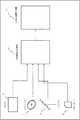
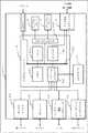
図1は、立体映像表示制御装置1と他の装置との関係を示す図である。図2は、立体映像表示制御装置1の構成例を示す図である。以下、具体的に説明する。 FIG. 1 is a diagram illustrating a relationship between the stereoscopic video
〔1.立体映像表示制御装置1と他の装置との関係〕
立体映像表示制御装置1は、立体映像を表示するための立体映像表示装置2、立体映像ストリームが蓄積されているサーバ3、光ディスク4、アンテナ5及びメモリカード6と接続されている。[1. Relationship between stereoscopic image
The stereoscopic video
立体映像表示装置2は、液晶ディスプレイ、プラズマディスプレイ、又は、有機ELディスプレイ等のディスプレイ24を備え、映像データを表示するものである。立体映像表示装置2は、立体映像表示制御装置1から送信された映像データを表示可能である。なお、立体映像表示装置2は、立体映像表示制御装置1からの要求信号に基づき、画面サイズに関する情報を立体映像表示制御装置1に送信可能である。 The stereoscopic
具体的に立体映像表示装置2は、図3で示すように、コントローラ22、メモリ23、ディスプレイ24、データ伝送インターフェース21、および通信インターフェース25で構成されている。 Specifically, the stereoscopic
メモリ23には、自己の画面サイズに関する情報が予め記憶されている。メモリ23は、例えば、フラッシュメモリやFRAM等で実現可能である。 Information relating to its own screen size is stored in the
コントローラ22は、立体映像表示制御装置1から要求信号を受け付けると、メモリ23に記憶された画面サイズに関する情報を読み出して、立体映像表示制御装置1に送信する。これによって、立体映像表示制御装置1は、立体映像表示装置2から画面サイズに関する情報を取得できる。なお、コントローラ22は、例えば、マイクロプロセッサで実現できる。 When the
また、データ伝送インターフェース21は、立体映像表示制御装置1とデータの送受信を行なうためのインターフェースである。データ伝送インターフェース21は、例えば、HDMIコネクタ等で実現できる。 The
通信インターフェース25は、アクティブシャッターメガネ7と通信を行なうためのインターフェースである。通信インターフェース25は、例えば、赤外線やBluetoothなどの無線、又は、有線でアクティブシャッターメガネ7との通信を確立する。 The
サーバ3は、立体映像ストリームが蓄積されているネットワークサーバである。サーバ3は、ネットワークに接続されており、家庭内におかれた立体映像表示制御装置1と接続可能である。サーバ3は、立体映像表示制御装置1からのアクセス要求に対応して、立体映像ストリームを立体映像表示制御装置1(ネットワーク通信インターフェース13)に送信することが可能である。 The
光ディスク4は、立体映像ストリームが記録された記録メディアである。光ディスク4は、立体映像表示制御装置1のディスクドライブ11に挿入可能である。なお、立体映像表示制御装置1(ディスクドライブ11)は、光ディスク4に記録された立体映像ストリームを読み出すことが可能である。 The optical disc 4 is a recording medium on which a stereoscopic video stream is recorded. The optical disk 4 can be inserted into the disk drive 11 of the stereoscopic video
アンテナ5は、放送局の放送装置から放送された立体映像ストリームを含む放送波を受信するためのアンテナである。アンテナ5は、立体映像表示制御装置1(チューナー12)に対して受信した立体映像ストリームを含む放送波を送信するものである。 The
メモリカード6は、立体映像ストリームが記録された半導体メモリカード、又は半導体メモリを内部に有した記録媒体である。メモリカード6は、立体映像表示制御装置1(データ伝送インターフェース15)に挿入可能である。なお、立体映像表示制御装置1(データ伝送インターフェース15)は、メモリカード6に記録された立体映像ストリームを読み出すことが可能である。 The memory card 6 is a semiconductor memory card in which a stereoscopic video stream is recorded, or a recording medium having a semiconductor memory inside. The memory card 6 can be inserted into the stereoscopic video display control device 1 (data transmission interface 15). Note that the stereoscopic video display control apparatus 1 (data transmission interface 15) can read the stereoscopic video stream recorded on the memory card 6.
〔2.立体映像の撮影方法及び表示方法〕
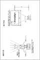
本実施の形態の具体的な構成例を説明する前に、立体映像の撮影方法及び表示方法の一例を説明する(図4)。図4は、立体映像の撮影方法及び表示方法を説明するための図である。[2. 3D image shooting method and display method]
Before describing a specific configuration example of the present embodiment, an example of a stereoscopic image capturing method and a display method will be described (FIG. 4). FIG. 4 is a diagram for explaining a stereoscopic video capturing method and display method.
まず、立体映像の撮影方法について説明する。立体映像は、左眼用カメラと右眼用カメラとを有する複眼カメラで撮影可能である。本実施の形態の複眼カメラは、左眼用カメラの光軸と右眼用カメラの光軸を平行にした状態で立体映像を撮影するものである。なお、本実施の形態では、上記のような複眼カメラを対象としたがこれに限られず、立体映像を撮影可能なカメラであれば、仕様は特に拘わらなくてよい。 First, a method for capturing a stereoscopic image will be described. A stereoscopic image can be taken with a compound eye camera having a left-eye camera and a right-eye camera. The compound eye camera of the present embodiment captures a stereoscopic image in a state where the optical axis of the left-eye camera and the optical axis of the right-eye camera are parallel. In the present embodiment, the compound eye camera as described above is targeted. However, the present invention is not limited to this, and the specification is not particularly limited as long as the camera can capture a stereoscopic image.
上述した複眼カメラにおいて、立体映像を撮影する場合、左右のカメラの各々で動画像を撮影する。このようにして複眼カメラでは、立体映像を表示するのに必要な、左眼用カメラで撮影された左眼映像と、右眼用カメラで撮影された右眼映像を生成する。具体的には、図7のような、左眼映像と右眼映像が生成される。 In the above-described compound eye camera, when shooting a stereoscopic video, a moving image is shot with each of the left and right cameras. In this way, the compound eye camera generates a left-eye image captured by the left-eye camera and a right-eye image captured by the right-eye camera, which are necessary for displaying a stereoscopic image. Specifically, a left eye image and a right eye image as shown in FIG. 7 are generated.
複眼カメラ(立体映像記録回路)は、このようにして生成された左眼映像と右眼映像を立体映像データとして記録メディア(例えば、光ディスクやメモリカード)に記録する。これによって、複眼カメラは、立体映像を表示する際に必要な立体映像データを生成できる。 The compound-eye camera (stereoscopic video recording circuit) records the left-eye video and right-eye video generated in this way as stereoscopic video data on a recording medium (for example, an optical disk or a memory card). Thereby, the compound eye camera can generate the stereoscopic video data necessary when displaying the stereoscopic video.
ここで本実施の形態では、図示しない編集機器で、複眼カメラで生成された立体映像データに、関連情報を付加するようにしている。関連情報には、立体映像の視差情報、立体映像に付加される副映像、字幕映像、そして、立体映像に付加される副映像の視差情報、及び、字幕映像の視差情報が含まれている。立体映像に付加される副映像の視差情報及び字幕映像の視差情報は、立体映像との関係で奥行き方向の違和感が発生しないよう調整された情報である。つまり、字幕映像の視差情報は、立体映像の表示位置よりも字幕映像の表示位置が、視聴者に対して近くに位置するよう調整されている。したがって、立体映像表示制御装置1は、上記情報を取得し、立体映像データに字幕映像を重ね合わせて、立体映像表示装置2に表示させる際、違和感のない立体映像を視聴者に提供できるようになっている。なお、本実施の形態では、立体映像データと関連情報を併せて、立体映像ストリームと呼ぶ。また、具体的な立体映像ストリームの構成は、後述する。 Here, in the present embodiment, related information is added to stereoscopic video data generated by a compound eye camera with an editing device (not shown). The related information includes stereoscopic video parallax information, sub video added to the stereoscopic video, subtitle video, sub video parallax information added to the stereoscopic video, and subtitle video parallax information. The parallax information of the sub-video and the parallax information of the subtitle video added to the stereoscopic video is information adjusted so that a sense of incongruity in the depth direction does not occur in relation to the stereoscopic video. That is, the parallax information of the caption video is adjusted so that the display position of the caption video is closer to the viewer than the display position of the stereoscopic video. Therefore, when the stereoscopic video
次に、立体映像の表示方法について説明する。立体映像表示装置2は、図5のように、アクティブシャッターメガネ7を用いて立体映像を視聴する表示装置である。立体映像表示装置2の立体映像の表示例を説明する。立体映像表示制御装置1は、立体映像表示装置2に対して、左眼映像が示す画像データと右眼映像が示す画面データを交互に出力する。立体映像表示装置2では、立体映像表示制御装置1から取得した画面データをディスプレイ24の画面上に順次表示する。 Next, a method for displaying a stereoscopic image will be described. As shown in FIG. 5, the stereoscopic
この際、立体映像表示制御装置1は、関連情報に含まれた立体映像の視差情報に基づいて、左眼映像と右眼映像の表示画面内の表示位置(オフセット)を調整する。このようにしてディスプレイ24に表示された表示画面を、ユーザは、アクティブシャッターメガネ7を介して視聴する。 At this time, the stereoscopic video
アクティブシャッターメガネ7は、ユーザの左右の何れかの視野を遮ることが可能に構成されている。したがって、アクティブシャッターメガネ7は、立体映像表示装置2に左眼映像が表示されると、ユーザの立体映像表示装置2に対する右眼の視野を遮る。一方で、アクティブシャッターメガネ7は、立体映像表示装置2に右眼映像が表示されると、ユーザの立体映像表示装置2に対する左眼の視野を遮る。つまり、図5のように、立体映像表示装置2に左眼映像を示す画面が表示されている場合は、ユーザは、左眼で映像を見ることになり、立体映像表示装置2に右眼映像を示す画面が表示されている場合は、ユーザは、右眼で映像を見ることになる。これによって、ユーザは、立体映像表示装置2に順次表示された画面を、立体映像として捉えることができる。 The
ここで、ユーザが立体映像を最適な状態で視聴することができる無歪み条件を説明する。なお複眼カメラは、左眼用カメラの光軸と右眼用カメラの光軸を平行にした状態で立体映像を撮影しているものとする。この場合、無歪み条件は、複眼カメラが立体映像を撮影した際の画角と、ユーザが立体映像表示装置を視聴する際の画角が一致し、かつ、複眼カメラが立体映像を撮影した際の左眼映像及び右眼映像のオフセットと、立体映像表示装置に立体映像を表示する際の左眼映像及び右眼映像のオフセットが一致することをいう。 Here, a non-distortion condition that allows the user to view a stereoscopic image in an optimal state will be described. It is assumed that the compound-eye camera captures a stereoscopic image in a state where the optical axis of the left-eye camera and the optical axis of the right-eye camera are parallel. In this case, the no-distortion condition is that the angle of view when the compound-eye camera captures the stereoscopic image matches the angle of view when the user views the stereoscopic image display device, and the compound-eye camera captures the stereoscopic image. The left-eye video and right-eye video offsets coincide with the left-eye video and right-eye video offsets when the stereoscopic video is displayed on the stereoscopic video display device.
例えば、図4において、立体映像データが、左右のカメラ間の距離情報65mm、焦点距離50mmで撮影されたとする。左右のカメラ間の距離情報65mmは、人間の目の間の距離(約63mm〜68mm)に相当する値である。また、焦点距離50mm(画角46度)は、人間が普段見ている遠近感とほぼ等しい値である
このような場合、例えば、立体映像表示装置の横方向の画面サイズWと、立体映像表示装置の最適な視聴距離Lを調整して、画角を一致させればよい。画角を一致させるとは、θcとθdを一致させることである。For example, in FIG. 4, it is assumed that stereoscopic video data is captured with distance information between the left and right cameras of 65 mm and a focal length of 50 mm. The distance information 65 mm between the left and right cameras is a value corresponding to the distance between human eyes (approximately 63 mm to 68 mm). Further, the focal length 50 mm (angle of view 46 degrees) is a value that is almost equal to the perspective normally seen by humans. In this case, for example, the horizontal screen size W of the stereoscopic video display device and the stereoscopic video display The viewing angle L may be adjusted by adjusting the optimum viewing distance L of the apparatus. Matching the angle of view means matching θc and θd.
また、上記のオフセットを一致させるため、左眼映像及び右眼映像を、画面内で以下のように調整して表示する。 In order to match the above-described offsets, the left eye image and the right eye image are adjusted and displayed on the screen as follows.
立体映像表示制御装置1は、左眼映像の画面内の表示位置を、画面の中心から、左へ(dc/2)mm、つまり、32.5mm分移動するよう調整する。また、立体映像表示制御装置は、右眼映像の画面内の表示位置を、画面の中心から、右へ(dc/2)mm、つまり、32.5mm分移動するよう調整する。このようにして、立体映像データを表示する際の左眼映像及び右眼映像の表示の位置の関係を、立体映像データを撮影する際の左眼及び右眼カメラの距離情報に一致させることができる。すなわち、撮影時のカメラ間の距離情報dcと、左眼映像と右眼映像の画面内の表示位置の関係ddを一致させることができる。 The stereoscopic image
上記のようにすれば、複眼カメラが立体映像を撮影した際の画角と、ユーザが立体映像表示装置を視聴する際の画角を一致させることができ、かつ、複眼カメラが立体映像を撮影した際の右眼映像と左眼映像のオフセットと、立体映像表示装置に立体映像を表示する際のオフセットを一致させることができる。このような状況で立体映像を視聴した場合、ユーザはより最適な立体映像を視聴することができる。 According to the above configuration, the angle of view when the compound-eye camera captures the stereoscopic image can be matched with the angle of view when the user views the stereoscopic image display device, and the compound-eye camera captures the stereoscopic image. The offset between the right-eye image and the left-eye image when the image is displayed can be matched with the offset when the stereoscopic image is displayed on the stereoscopic image display device. When viewing stereoscopic video in such a situation, the user can view more optimal stereoscopic video.
なお、上記実施の形態では、立体映像表示装置2は、アクティブシャッターメガネ7を用いた表示装置を説明したが、これに限られない。 In the above embodiment, the stereoscopic
〔3.立体映像ストリームの説明〕
本実施の形態において、立体映像表示制御装置1が、サーバ3、光ディスク4、アンテナ5及びメモリカード6などから取得する立体映像ストリームは、以下のような構成を持っている。図6に立体映像ストリームの構造の一例を示した。立体映像ストリームは、立体映像データと、立体映像データの関連情報と、で構成される。[3. Explanation of stereoscopic video stream)
In the present embodiment, the stereoscopic video stream acquired by the stereoscopic video
立体映像ストリームに含まれる立体映像データは、複眼カメラの左右のカメラで撮影された映像を、任意の圧縮方式で符号化した情報である。任意の圧縮方式には、MVC(Multi−view Video Coding)やMPEG4−AVC/H.264などが考えられるが、これに限られない。なお、圧縮された立体映像データには、上記圧縮方式で圧縮されているため、デコードするために必要な情報(デコード情報)が付加されている。 The stereoscopic video data included in the stereoscopic video stream is information obtained by encoding video captured by the left and right cameras of the compound-eye camera using an arbitrary compression method. As an arbitrary compression method, MVC (Multi-view Video Coding), MPEG4-AVC / H. H.264 is conceivable, but is not limited to this. Since the compressed stereoscopic video data is compressed by the above compression method, information (decoding information) necessary for decoding is added.
立体映像データの関連情報には、立体映像の視差情報、立体映像に付加される副映像、字幕映像、そして、立体映像に付加される副映像の視差情報、及び、字幕映像の視差情報が含まれている。 The related information of the stereoscopic video data includes the parallax information of the stereoscopic video, the sub-video added to the stereoscopic video, the subtitle video, the parallax information of the sub-video added to the stereoscopic video, and the parallax information of the subtitle video. It is.
立体映像の視差情報は、左眼映像と右眼映像のズレ量を示している。つまり、左眼映像と右眼映像とを表示装置に表示する際、どの程度、画面内でずらす必要があるかを示している。例えば、立体映像の視差情報が W mmである場合、画面内において、左眼映像を W/2 mm左方向にずらし、右眼映像を W/2 mm右方向にずらすとよいことになる。 The parallax information of the stereoscopic video indicates the amount of deviation between the left eye video and the right eye video. That is, it shows how much the left eye image and the right eye image need to be shifted in the screen when displayed on the display device. For example, when the parallax information of the stereoscopic video is W mm, it is better to shift the left eye video to the left by W / 2 mm and the right eye video to the right by W / 2 mm on the screen.
一方、字幕映像の視差情報は、左眼映像及び右眼映像に対して、字幕映像をどの程度ずらして重ね合わせればよいかを示している。本実施の形態では、字幕映像の視差情報は、立体映像データに対する相対的なズレ量を示している。例えば、字幕映像のズレ量が Y mmである場合、左眼映像に対して字幕映像を Y/2 mm左方向にずらして重ね合わせ、右眼映像に対して字幕映像を Y/2 mm右方向にずらして重ね合わせればよいことになる。なお、立体映像に付加される副映像の視差情報も同様である。また、ズレ量をあらわす視差情報は、mm単位で表現しているが、これに限られず、ズレ量を映像データ内の画素を表すピクセル数で表現してもよい。 On the other hand, the parallax information of the caption video indicates how much the caption video should be shifted and superimposed on the left-eye video and the right-eye video. In the present embodiment, the parallax information of the caption video indicates a relative shift amount with respect to the stereoscopic video data. For example, when the amount of deviation of the subtitle video is Y mm, the subtitle video is shifted Y / 2 mm to the left and superimposed on the left eye video, and the subtitle video is Y / 2 mm right to the right eye video. It is only necessary to shift and superimpose. The same applies to the parallax information of the sub-picture added to the stereoscopic video. Further, the disparity information representing the amount of deviation is expressed in mm units, but the present invention is not limited to this, and the amount of deviation may be expressed by the number of pixels representing pixels in the video data.
〔3.立体映像表示制御装置1の構成〕
立体映像表示制御装置1の構成を説明する。立体映像表示制御装置1は、ディスクドライブ11、チューナー12、ネットワーク通信インターフェース13、メモリデバイスインターフェース14、データ伝送インターフェース15、バッファメモリ(フレームメモリ)16、HDドライブ17、フラッシュメモリ19及びLSI18を備える。以下、各々の構成について具体的に説明する。[3. Configuration of stereoscopic video display control apparatus 1]
The configuration of the stereoscopic video
ディスクドライブ11は、光ピックアップ等で構成され、光ディスク4から立体映像ストリームを読み出す。ディスクドライブ11は、LSI18と接続されており、光ディスク4から読み出した立体映像ストリームをLSI18に送信する。ディスクドライブ11は、LSI18からの制御に応じて、光ディスク4から立体映像ストリームを読み出し、LSI18に送信する。 The disk drive 11 is composed of an optical pickup or the like, and reads a stereoscopic video stream from the optical disk 4. The disk drive 11 is connected to the
チューナー12は、アンテナ5で受信した立体映像ストリームを含む放送波を取得する。チューナー12は、取得した放送波の内、LSI18によって指定された周波数の立体映像ストリームを取り出す。チューナー12は、LSI18と接続されており、取り出した立体映像ストリームをLSI18に送信する。 The
ネットワーク通信インターフェース13は、ネットワークを介してサーバ3と接続可能である。ネットワーク通信インターフェース13は、サーバ3から送信された立体映像ストリームを取得する。 The
メモリデバイスインターフェース14は、メモリカード6を装着可能に構成されており、装着されたメモリカード6から立体映像ストリームを読み出すことが可能である。メモリデバイスインターフェース14は、メモリカード6から読み出された立体映像ストリームを、LSI18に送信する。 The
HDドライブ17は、ハードディスクなどの記録媒体を内蔵して構成され、記録媒体から読み出されたデータを、LSI18に送信する。また、HDドライブ17は、LSI18から受信したデータを、記録媒体に記録する。 The
データ伝送インターフェース15は、LSI18から送信されたデータを、外部の立体映像表示装置2に送信するためのインターフェースである。データ伝送インターフェース15は、データ信号及びコントロール信号を、立体映像表示装置2との間で送受信可能に構成されている。したがって、LSI18は、データ伝送インターフェース15を介して、立体映像表示装置2を制御することが可能になっている。データ伝送インターフェース15は、例えば、HDMIコネクタ等で実現可能である。なお、データ伝送インターフェース15は、データ信号を立体映像表示装置2に送信できれば、どのような構成であってもかまわない。 The
バッファメモリ16は、LSI18が処理を行う際に、ワークメモリとして作用する。バッファメモリ16は、例えば、DRAMやSRAMなどで実現可能である。 The
フラッシュメモリ19は、装置画像が予め記録されている。装置画像には、例えば、チャンネルの情報や音量の情報、ディスプレイの輝度・コントラスト量・色温度などを調整するための情報、再生装置の画質を調整するための情報を示す画像が含まれている。すなわち、LSI18は、フラッシュメモリ19から読み出した装置画像を映像データに重ね合わせて立体映像表示装置2に表示させることができる。これによって、LSI18は、視聴者に装置の情報を提供できる。また、LSI18は、視聴者に設定画面を表示して、視聴者からの設定を受け付けることが可能になる。 In the flash memory 19, an apparatus image is recorded in advance. The device image includes, for example, an image indicating channel information and volume information, information for adjusting display brightness, contrast amount, color temperature, and the like, and information for adjusting the image quality of the playback device. . That is, the
LSI18は、立体映像表示制御装置1の各部を制御するコントローラである。マイクロコンピュータで実現してもよく、ハードワイヤードな回路で実現してもよい。 The
LSI18の内部には、CPU181、ストリームコントローラ182、デコーダー183、AV入出力回路184、システムバス185及びメモリコントローラ186が実装されている。 Inside the
個々の構成を具体的に説明すると、CPU181は、LSI18全体を制御するものである。LSI18の各部は、LSI18からの制御に基づいて、各種制御を行なうように構成されている。また、CPU181は、外部との通信も制御する。例えば、CPU181は、データ伝送インターフェース15を介して立体映像表示装置2に要求信号を送信し、画面サイズに関する情報を取得することが可能である。CPU181は、取得した画面サイズに関する情報を、メモリコントローラ186を介してバッファメモリ16に記録する。また、CPU181は、サーバ3や光ディスク4、アンテナ5、メモリカード6から立体映像ストリームを取得する際、ディスクドライブ11やチューナー12、ネットワーク通信インターフェース13、メモリデバイスインターフェース14に制御信号を送信する。これによってディスクドライブ11やチューナー12、ネットワーク通信インターフェース13、メモリデバイスインターフェース14は、記録メディアや放送局等から立体映像ストリームを取得することができる。 The individual configuration will be specifically described. The
ストリームコントローラ182は、サーバ3や光ディスク4、アンテナ5、メモリカード6、アクティブシャッターメガネ7との間のデータの送受信を制御するものである。例えば、CPU181は、サーバ3から取得した立体映像ストリームを、メモリコントローラ186に送信する。 The
メモリコントローラ186は、LSI18の各部から送信されたデータを、バッファメモリ16に書き込む。例えば、メモリコントローラ186は、ストリームコントローラ182から取得した立体映像ストリームを、バッファメモリ16に記録する。また、メモリコントローラ186は、バッファメモリ16に記録されたデータを、バッファメモリ16から読み出す。そして、バッファメモリ16は、読み出したデータをLSI18の各部に送信する。 The
デコーダー183は、メモリコントローラ186からデータを取得すると、取得したデータをデコードする。ここで、デコーダー183に入力されるデータは、CPU181の制御に基づいている。具体的には、CPU181は、メモリコントローラ186を制御して、バッファメモリ16に記録された立体映像ストリームを読み出させる。そして、CPU181は、読み出した立体映像ストリームをデコーダー183に送信するようメモリコントローラ186を制御する。これによって、メモリコントローラ186からデコーダー183に立体映像ストリームが入力される。 When the
具体的にデコーダー183では、入力された立体映像ストリームを分離する。本実施の形態では、デコーダー183は、立体映像ストリームから立体映像データと関連情報を分離する。そして、デコーダー183は、関連情報をバッファメモリ16に記録する。 Specifically, the
また、デコーダー183は、立体映像データに含まれるデコード情報に基づいて、圧縮された立体映像データをデコードする。なお、デコーダー183は、デコードした情報をメモリコントローラ186に送信する。メモリコントローラ186では、取得した立体映像データを、バッファメモリ16に記録する。 Further, the
AV入出力回路184は、バッファメモリ16から立体映像データ及び関連情報、画面サイズに関する情報を読み出して、立体映像表示装置2に表示させる表示画像を生成する。そして、AV入出力回路184は、生成した表示画像を、データ伝送インターフェース15を介して立体映像表示装置2に送信する。 The AV input /
具体的には、AV入出力回路184は、立体映像データ及び立体映像の視差情報、画面サイズに関する情報を読み出す。そしてAV入出力回路184は、立体映像の視差情報及び画面サイズに関する情報に基づいて、立体映像データを画面内の表示位置(視差情報)を決定する。そしてAV入出力回路184は、決定された視差情報に基づいて、立体映像データの表示位置を調整した表示画面のデータを、データ伝送インターフェース15を介して立体映像表示装置2に出力する。なお、視差情報は、立体映像データの左眼映像と右眼映像との画面内での表示位置のずれ量を示す情報である。したがって、AV入出力回路184は、例えば、視差情報が30mmであれば、左眼映像の中心と右眼映像の中心を30mmずらして、表示装置に表示させるよう表示画面を生成する。この場合、AV入出力回路184は、例えば、表示画面の中心に対して、左眼映像を左へ15mmずらした表示画面を生成する。また、立体映像表示制御装置1は、表示画面の中心に対して、右眼映像を右へ15mmずらした表示画面を生成する。AV入出力回路184は、このようにして生成した表示画面を示すデータを、データ伝送インターフェース15を介して立体映像表示装置2に送信する。これによって、立体映像表示装置2では、左眼映像を示す表示画面及び右眼映像を示す表示画面が順次表示される。 Specifically, the AV input /
なお、AV入出力回路184は、字幕映像(又は、立体映像に付加される副映像)を立体映像データに重ね合わせるよう設定された場合、以下のように制御を行なう(図8)。AV入出力回路184は、関連情報をバッファメモリ16より取得し、関連情報に含まれる字幕映像の視差情報に基づいて、左眼映像及び右眼映像に字幕映像を重ね合わせる。重ね合わせる位置は、以下の通りである。AV入出力回路184は、例えば、字幕映像の視差情報(ズレ量)が Y mmである場合、左眼映像に対して字幕映像を Y/2 mm左方向にずらして重ね合わせ、右眼映像に対して字幕映像を Y/2 mm右方向にずらして重ね合わせる。立体映像に付加される副映像も同様である。 When the AV input /
ここで本実施の形態では、ユーザが、装置画像を立体映像データに重ねて表示するよう指示する場合がある(図8)。この場合、CPU181は、以下の制御を行なう。 Here, in the present embodiment, the user may instruct to display the device image superimposed on the stereoscopic video data (FIG. 8). In this case, the
まず、CPU181は、リモコンを介してユーザからの指示を受け付ける。リモコンからの指示は、立体映像表示制御装置1に設けられる赤外線センサで受信する。CPU181は、ユーザからの指示が、装置画像の表示(例えば、装置の機能メニュー画面の表示)である場合、フラッシュメモリ19より指示に対応する装置画像(機能メニュー画像)を取得する。そして、CPU181は、バッファメモリ16から字幕映像の視差情報(又はメニュー画面の視差情報)を取得する。CPU181は、この取得した字幕映像の視差情報に基づいて、装置画像の視差情報を決定する。具体的に、CPU181は、装置画像の視差情報(例えば Z mm)が、字幕映像の視差情報(例えば Y mm)よりも大きくなるようにする。 First, the
なお、本実施の形態では、CPU181は、装置画像の視差情報が、字幕映像の視差情報よりも大きくなるように構成したが、装置画像の視差情報が、立体映像に付加される副映像の視差情報よりも大きくなるように構成してもかまわない。すなわち、CPU181は、立体映像に関連する付加情報の、少なくとも1つの視差情報よりも装置画像の視差情報を大きくできるものであれば、どのような構成であってもかまわない。よって、CPU181は、立体映像に関連する付加情報の全ての視差情報よりも装置画像の視差情報を大きくするようにしてよい。 In the present embodiment, the
説明に戻って、CPU181は、このようにして得られた視差情報をAV入出力回路184に入力し、AV入出力回路184に装置画像を立体画像に重ね合わせるよう指示を出す。 Returning to the description, the
AV入出力回路184は、受信した装置画像の視差情報に基づき、立体映像に装置画像を重ね合わせる。例えば、装置画像の視差情報(ズレ量)が Z mmである場合、左眼映像に対して装置画像を Z/2 mm左方向にずらして重ね合わせ、右眼映像に対して装置画像を Z/2 mm右方向にずらして重ね合わせる。AV入出力回路184は、このようにして装置画像を重ね合わせた左眼映像及び右眼映像に対して、上記説明した視差情報で画面全体にオフセットをつけ、表示画面を示すデータを生成する。AV入出力回路184は、このようにして生成された表示画面を示すデータを、立体映像表示装置2に出力する。 The AV input /
これによって、立体映像表示制御装置1は、容易な手段で装置内の画像(装置画像)を立体映像に付加することができ、ユーザに対して表示する装置内の画像(装置画像)の奥行き方向の違和感を軽減できる。 Thereby, the stereoscopic video
なお、図示しないが、立体映像表示制御装置1の各部には電源が接続されており、電源から電力が供給されるように構成されている。 Although not shown, a power source is connected to each part of the stereoscopic video
〔4.立体映像表示制御装置1の動作〕
次に、立体映像表示制御装置1の動作例を、図10のフローチャートに基づいて説明を行なう。アンテナ5で得られた放送波に含まれる立体映像ストリームを立体映像表示装置2に表示させる場合を例にして説明を行なう。立体映像表示制御装置1は、アンテナ5から立体映像ストリームを取得するように設定されると、以下の動作を開始する。[4. Operation of stereoscopic image display control apparatus 1]
Next, an operation example of the stereoscopic image
まず、LSI18は、立体映像表示装置2に要求信号を送信して、立体映像表示装置2の画面サイズに関する情報を取得する。そしてLSI18は、取得した画面サイズに関する情報をバッファメモリ16に記憶する(S1)。そしてLSI18は、チューナー12を制御して、アンテナ5で得られた放送波から、立体映像ストリームを取得する(S2)。LSI18は、取得した立体映像ストリームをバッファメモリ16に記憶する(S3)。LSI18は、バッファメモリ16に記憶された立体映像ストリームを読み出し、立体映像ストリームを立体映像データ及び関連情報に分離する(S4)。LSI18は、分離した関連情報をバッファメモリ16に記憶する。一方でLSI18は、分離した立体映像データをデコードし、デコードした立体映像データをバッファメモリ16に記憶する(S5)。LSI18は、バッファメモリ16に記憶された画面サイズに関する情報、関連情報に含まれる立体映像の視差情報に基づいて、立体映像データの左眼映像と右眼映像の視差情報を算出する(S6)。 First, the
具体的には、以下の方法で、画面サイズに関する情報に基づいて、左眼映像と右眼映像の視差情報を調整する。つまり、LSI18は、画面サイズが大きければ、視差情報を大きくなるように調整し、画面サイズが小さければ、視差情報を小さくなるように調整する。 Specifically, the parallax information of the left eye video and the right eye video is adjusted based on information on the screen size by the following method. That is, the
LSI18は、算出された視差情報に基づいて、デコードされた立体映像データに含まれる左眼映像、又は、右眼映像を表示画面にする(S7)。LSI18は、左眼映像及び右眼映像を示す表示画面を立体映像表示装置2に出力する(S8)。LSI18は、上記動作を繰り替えし行ない立体映像表示装置2に表示画面を順次出力する。 Based on the calculated parallax information, the
次に、ユーザによって装置画像の表示が指示された場合の動作例を図11で説明する。 Next, an operation example when the display of the device image is instructed by the user will be described with reference to FIG.
ステップT1〜T5は、ステップS1〜S5と同様なので、説明を省略する。ステップT5の後、LSI18は、バッファメモリ16から字幕映像の視差情報を取得し、この取得した字幕映像の視差情報に基づいて、装置画像の視差情報を算出する(T6)。そして、LSI18は、算出した装置画像の視差情報に基づき、立体映像データに装置画像を重ね合わせる(T7)。重ね合わせた画像が重畳画像である。 Since steps T1 to T5 are the same as steps S1 to S5, description thereof is omitted. After step T5, the
ここで、装置画像に加えて字幕画像を立体映像データに重ね合わせることも可能である。このような場合、装置画像は、字幕画像よりも立体視された際に手前に表示されるようになる。これによって、装置画像が立体映像に対して違和感のない映像となる。 Here, in addition to the device image, it is also possible to superimpose a caption image on the stereoscopic video data. In such a case, the device image is displayed in front of the subtitle image when stereoscopically viewed. As a result, the device image becomes a video that does not feel uncomfortable with the stereoscopic video.
この後、LSI18は、ステップS6〜S8と同様の動作を行なう(T8〜T10)。なおLSI18は、上記動作を繰り返し行ない、立体映像表示装置2に表示画面を順次出力する。なお、上記動作を繰り返し行なう際、ステップT6の動作は、二回目以降は省略するようにしてもよい。 Thereafter, the
本実施の形態によれば、例えば、字幕映像の視差情報に基づいて、装置画像の視差情報を調整できるので、容易な手段で、立体画像に対する装置画像の表示の違和感を軽減できる。 According to the present embodiment, for example, the parallax information of the device image can be adjusted based on the parallax information of the caption video, and therefore, the uncomfortable feeling of the display of the device image with respect to the stereoscopic image can be reduced with an easy means.
ここで本実施の形態が解決する課題および効果を簡単に説明する。本実施の形態のように字幕映像の視差情報に基づいて装置画像の視差情報を調整しない場合、立体映像データから最も前面に存在する物体の奥行き方向の位置を算出する必要がでてくる。これでは、立体映像データに装置画像を重ねて表示しようとする際に、一々立体映像データを解析しなければならなくなるため、時間がかかってしまう。そこで、本実施の形態のように構成すれば、装置画像を立体映像データに重ねる際、装置画像の違和感を軽減しつつ、短時間で実現できる。 Here, the problem and effect which this Embodiment solves are demonstrated easily. When the parallax information of the device image is not adjusted based on the parallax information of the caption video as in the present embodiment, it is necessary to calculate the position in the depth direction of the object existing in the foreground from the stereoscopic video data. This takes time because it is necessary to analyze the stereoscopic video data one by one when attempting to display the device image superimposed on the stereoscopic video data. Therefore, when configured as in the present embodiment, when the device image is superimposed on the stereoscopic video data, it can be realized in a short time while reducing the uncomfortable feeling of the device image.
また、本実施の形態では、立体映像データに付加される関連情報に、立体映像に関する字幕映像(又は、副映像)の視差情報を付加していることが前提である。すなわち、立体映像データを作成するコンテンツ事業者は、立体映像データとの整合を考えて、違和感のないように、字幕映像の視差情報を、立体映像データに付加しているはずである。したがって、本実施の形態では、このような背景に基づいて、実現している。つまり、本実施の形態では、立体映像データに付加された字幕映像の視差情報に基づいて、装置画像の視差情報を決定する。これによって、立体映像表示制御装置は、立体映像データに対する装置画像の重ね合わせの位置である視差情報を、容易に決定でき、立体映像データに対する装置画像の重ね合わせを、違和感を軽減した状態で設定できる。 Further, in the present embodiment, it is assumed that parallax information of subtitle video (or sub-video) related to stereoscopic video is added to related information added to stereoscopic video data. That is, the content provider who creates the stereoscopic video data should add the parallax information of the caption video to the stereoscopic video data so as not to feel uncomfortable considering the matching with the stereoscopic video data. Therefore, this embodiment is realized based on such a background. That is, in the present embodiment, the parallax information of the device image is determined based on the parallax information of the caption video added to the stereoscopic video data. Thereby, the stereoscopic video display control apparatus can easily determine the parallax information that is the position of the superimposition of the device image on the stereoscopic video data, and sets the superimposition of the device image on the stereoscopic video data in a state in which a sense of incongruity is reduced. it can.
なお、図12のように、立体映像に重畳される字幕映像や副映像が左眼映像、右眼映像の両方の映像を持っている場合には、字幕映像、又は、副映像の左眼映像及び右眼映像によって左右の視差情報を算出するようにするとよい。このようにすれば、主映像(立体映像)の映像データの解析が必要なくなるので、より簡易な手段で、立体映像に対する違和感のない装置画像の視差情報を算出できる。
〔5.本実施の形態の本発明の対応関係〕
立体映像表示制御装置1は、表示制御装置の一例である。また、立体映像データは、立体映像情報の一例と、字幕映像は、第1付加画像の一例である。装置画像は、第2付加画像の一例である。字幕映像の視差情報は、第1位置情報の一例である。装置画像の視差情報は、第2位置情報の一例である。In addition, as shown in FIG. 12, when the subtitle video or the sub video superimposed on the stereoscopic video has both the left eye video and the right eye video, the subtitle video or the left eye video of the sub video is displayed. The right and left parallax information may be calculated from the right eye image. In this way, analysis of the video data of the main video (stereoscopic video) is not necessary, so that the parallax information of the device image without any sense of incongruity with the stereoscopic video can be calculated with simpler means.
[5. Correspondence of the present embodiment to the present invention]
The stereoscopic video
LSI18は、取得手段、付加手段の一例である。LSI18は、第1取得手段、第2取得手段、決定手段の一例である。
〔6.まとめ〕
本実施の形態における立体映像表示制御装置1は、立体映像データと、立体映像データに重ね合わせて表示可能な字幕映像と、字幕映像の視差情報と、を取得するLSI18と、装置画像を取得する第2取得手段と、字幕映像の視差情報に基づいて、装置画像の視差情報を決定するLSI18と、装置画像の視差情報に基づいて、装置画像を立体映像情報に重ね合わせるLSI18と、を備える。The
[6. (Summary)
The stereoscopic video
このようにすれば、装置画像を立体映像に重ね合わせる場合において、より簡易な手段で立体映像に装置画像を重ね合わせることができ、立体映像に対する装置画像の奥行き方向の違和感を軽減できる。
(他の実施の形態)
本発明の一実施の形態として、実施例1を説明した。しかし、本発明は、これに限られず種々の形態で実現することが可能である。以下、他の実施の形態を説明する。In this way, when the device image is superimposed on the stereoscopic video, the device image can be superimposed on the stereoscopic video by a simpler means, and the uncomfortable feeling in the depth direction of the device image with respect to the stereoscopic video can be reduced.
(Other embodiments)
Example 1 has been described as an embodiment of the present invention. However, the present invention is not limited to this and can be realized in various forms. Hereinafter, other embodiments will be described.
本実施の形態では、字幕映像の視差情報を、立体映像データに対して相対的な情報で表現した例を説明した。しかし、これに限られず、字幕映像の視差情報を、絶対的な情報で表示してもよい。この場合、AV入出力回路184は、立体情報の視差情報を考慮して、左眼映像及び右眼映像に字幕映像を重ね合わせる。例えば、AV入出力回路184は、立体映像の視差情報が W mmであり、字幕映像の視差情報が K mmである場合、左眼映像に (K−W)/2 mmの左方向に対するオフセットを付けて、字幕映像を重ね合わせる。一方、AV入出力回路184は、上記条件の場合、右眼映像に (K−W)/2 mmの右方向に対するオフセットを付けて、字幕映像を重ね合わせる。AV入出力回路184は、このようにして生成した左眼映像及び右眼映像に対して、上記説明した視差情報で画面全体にオフセットをつけ、表示画面を示すデータを生成する。AV入出力回路184は、このようにして生成された表示画面を示すデータを、立体映像表示装置2に出力する。 In the present embodiment, the example in which the parallax information of the caption video is expressed by information relative to the stereoscopic video data has been described. However, the present invention is not limited to this, and the parallax information of the caption video may be displayed as absolute information. In this case, the AV input /
本発明は、立体映像を表示可能なテレビ受像機や、ディスプレイに接続可能な録再機に適用可能である。 The present invention can be applied to a television receiver capable of displaying a stereoscopic image and a recording / playback device connectable to a display.
1 立体映像表示制御装置
2 立体映像表示装置
3 サーバ
4 光ディスク
5 アンテナ
6 メモリカード
7 アクティブシャッターメガネ
11 ディスクドライブ
12 チューナー
13 ネットワーク通信インターフェース
14 メモリデバイスインターフェース
15 データ伝送インターフェース
16 バッファメモリ
17 HDドライブ
18 LSI
181 CPU
182 ストリームコントローラ
183 デコーダー
184 AV入出力回路
185 システムバス
186 メモリコントローラ
19 フラッシュメモリ
21 データ伝送インターフェース
22 コントローラ
23 メモリ
24 ディスプレイ
25 通信インターフェースDESCRIPTION OF
181 CPU
182
Claims (3)
Translated fromJapanese前記立体映像情報が示す立体映像に重畳させて表示される第2付加画像を示す第2付加情報を取得する第2取得手段と、
前記立体映像、前記第1付加画像および前記第2付加画像を重畳させた重畳画像を、前記第2付加画像が前記第1付加画像よりも立体視された際に手前に表示されるようにして、生成する生成手段と、
前記生成された重畳画像を表示する表示手段と、
を備える表示制御装置。First acquisition means for acquiring stereoscopic video information indicating a stereoscopic video, and first additional information indicating a first additional image displayed superimposed on the stereoscopic video indicated by the stereoscopic video information;
Second acquisition means for acquiring second additional information indicating a second additional image displayed superimposed on the stereoscopic video indicated by the stereoscopic video information;
The superimposed image obtained by superimposing the stereoscopic image, the first additional image, and the second additional image is displayed in front when the second additional image is stereoscopically viewed from the first additional image. Generating means for generating;
Display means for displaying the generated superimposed image;
A display control device.
前記立体映像情報が示す立体映像に重畳させて表示される第2付加画像を示す第2付加情報を取得する第2取得手段と、
前記第1位置情報に基づいて、前記第2付加画像の視聴者に対する奥行き方向の表示位置を示す第2位置情報を決定する決定手段と、
前記第2位置情報に基づいて、前記立体映像に前記第2付加画像を重畳させた重畳画像を生成する生成手段と、
前記生成された重畳画像を表示する表示手段と、
を備える表示制御装置。3D image information indicating a 3D image, 1st additional information indicating a 1st additional image displayed superimposed on the 3D image indicated by the 3D image information, and a display position of the first additional image in the depth direction for the viewer First position information indicating: first acquisition means for acquiring;
Second acquisition means for acquiring second additional information indicating a second additional image displayed superimposed on the stereoscopic video indicated by the stereoscopic video information;
Determining means for determining second position information indicating a display position of the second additional image in the depth direction for a viewer based on the first position information;
Generating means for generating a superimposed image obtained by superimposing the second additional image on the stereoscopic video based on the second position information;
Display means for displaying the generated superimposed image;
A display control device.
前記第2付加画像は、装置内に予め記録された情報である、
請求項1に記載の表示制御装置。The first additional image is information acquired from the outside,
The second additional image is information recorded in advance in the apparatus.
The display control apparatus according to claim 1.
Priority Applications (1)
| Application Number | Priority Date | Filing Date | Title |
|---|---|---|---|
| PCT/JP2010/000871WO2010092823A1 (en) | 2009-02-13 | 2010-02-12 | Display control device |
Applications Claiming Priority (2)
| Application Number | Priority Date | Filing Date | Title |
|---|---|---|---|
| US15253109P | 2009-02-13 | 2009-02-13 | |
| US61/152531 | 2009-02-13 |
Publications (1)
| Publication Number | Publication Date |
|---|---|
| JP2012089906Atrue JP2012089906A (en) | 2012-05-10 |
Family
ID=46261096
Family Applications (1)
| Application Number | Title | Priority Date | Filing Date |
|---|---|---|---|
| JP2009101822APendingJP2012089906A (en) | 2009-02-13 | 2009-04-20 | Display controller |
Country Status (1)
| Country | Link |
|---|---|
| JP (1) | JP2012089906A (en) |
Cited By (5)
| Publication number | Priority date | Publication date | Assignee | Title |
|---|---|---|---|---|
| JP2010258609A (en)* | 2009-04-22 | 2010-11-11 | Sony Corp | Transmitting apparatus, stereoscopic image data transmitting method, receiving apparatus, and stereoscopic image data receiving method |
| JP2011010255A (en)* | 2009-10-29 | 2011-01-13 | Sony Corp | Three-dimensional image data transmitting method, and three-dimensional image data receiving apparatus and method |
| WO2013176315A1 (en)* | 2012-05-24 | 2013-11-28 | 엘지전자 주식회사 | Device and method for processing digital signals |
| WO2014013695A1 (en)* | 2012-07-19 | 2014-01-23 | パナソニック株式会社 | Image encoding method, image decoding method, image encoding device, and image decoding device |
| US8964000B2 (en) | 2012-05-24 | 2015-02-24 | Lg Electronics Inc. | Apparatus and method for processing digital signal |
- 2009
- 2009-04-20JPJP2009101822Apatent/JP2012089906A/enactivePending
Cited By (8)
| Publication number | Priority date | Publication date | Assignee | Title |
|---|---|---|---|---|
| JP2010258609A (en)* | 2009-04-22 | 2010-11-11 | Sony Corp | Transmitting apparatus, stereoscopic image data transmitting method, receiving apparatus, and stereoscopic image data receiving method |
| US8810563B2 (en) | 2009-04-22 | 2014-08-19 | Sony Corporation | Transmitting apparatus, stereoscopic image data transmitting method, receiving apparatus, and stereoscopic image data receiving method |
| JP2011010255A (en)* | 2009-10-29 | 2011-01-13 | Sony Corp | Three-dimensional image data transmitting method, and three-dimensional image data receiving apparatus and method |
| WO2013176315A1 (en)* | 2012-05-24 | 2013-11-28 | 엘지전자 주식회사 | Device and method for processing digital signals |
| US8964000B2 (en) | 2012-05-24 | 2015-02-24 | Lg Electronics Inc. | Apparatus and method for processing digital signal |
| WO2014013695A1 (en)* | 2012-07-19 | 2014-01-23 | パナソニック株式会社 | Image encoding method, image decoding method, image encoding device, and image decoding device |
| JPWO2014013695A1 (en)* | 2012-07-19 | 2016-06-30 | パナソニック インテレクチュアル プロパティ コーポレーション オブ アメリカPanasonic Intellectual Property Corporation of America | Image encoding method, image decoding method, image encoding device, and image decoding device |
| US10104360B2 (en) | 2012-07-19 | 2018-10-16 | Sun Patent Trust | Image encoding method, image decoding method, image encoding apparatus, and image decoding apparatus |
Similar Documents
| Publication | Publication Date | Title |
|---|---|---|
| WO2010092823A1 (en) | Display control device | |
| US20100265315A1 (en) | Three-dimensional image combining apparatus | |
| US8077964B2 (en) | Two dimensional/three dimensional digital information acquisition and display device | |
| US20130038611A1 (en) | Image conversion device | |
| US20120263372A1 (en) | Method And Apparatus For Processing 3D Image | |
| US20100182404A1 (en) | Three dimensional video reproduction apparatus, three dimensional video reproduction system, three dimensional video reproduction method, and semiconductor device for three dimensional video reproduction | |
| US9137523B2 (en) | Method and apparatus for controlling image display so that viewers selectively view a 2D or a 3D service | |
| JP5390016B2 (en) | Video processing device | |
| US20100238274A1 (en) | Method of displaying three-dimensional image data and an apparatus of processing three-dimensional image data | |
| JP5293500B2 (en) | Display device and control method | |
| US9869875B2 (en) | 3D display device and selective image display method thereof | |
| JP5502436B2 (en) | Video signal processing device | |
| US8836758B2 (en) | Three-dimensional image processing apparatus and method of controlling the same | |
| JP2012015774A (en) | Stereoscopic image processing device and stereoscopic image imaging method | |
| US20110310099A1 (en) | Three-dimensional image processing apparatus and method of controlling the same | |
| KR20110064161A (en) | Compression method and apparatus for 3D image, 3D image display apparatus and system | |
| EP2424259A2 (en) | Stereoscopic video display system with 2D/3D shutter glasses | |
| JP5390017B2 (en) | Video processing device | |
| JP6667981B2 (en) | Imbalance setting method and corresponding device | |
| US8941718B2 (en) | 3D video processing apparatus and 3D video processing method | |
| JP2012089906A (en) | Display controller | |
| KR20110140087A (en) | Stereo display device and display method of stereo display device | |
| WO2011024423A1 (en) | Control device for stereoscopic image display and imaging device for stereoscopic images | |
| JP2014022947A (en) | Stereoscopic video transmission apparatus, stereoscopic video transmission method, and stereoscopic video processing apparatus | |
| KR20110037068A (en) | Stereoscopic Equipment and Picture Quality Control |