JP2012086736A - Vehicular air conditioner - Google Patents
Vehicular air conditionerDownload PDFInfo
- Publication number
- JP2012086736A JP2012086736AJP2010236517AJP2010236517AJP2012086736AJP 2012086736 AJP2012086736 AJP 2012086736AJP 2010236517 AJP2010236517 AJP 2010236517AJP 2010236517 AJP2010236517 AJP 2010236517AJP 2012086736 AJP2012086736 AJP 2012086736A
- Authority
- JP
- Japan
- Prior art keywords
- temperature
- display
- air
- air conditioner
- vehicle
- Prior art date
- Legal status (The legal status is an assumption and is not a legal conclusion. Google has not performed a legal analysis and makes no representation as to the accuracy of the status listed.)
- Granted
Links
Images


Landscapes
- Air-Conditioning For Vehicles (AREA)
Abstract
Translated fromJapaneseDescription
Translated fromJapanese本発明は、車両に搭載される空調装置に関する。 The present invention relates to an air conditioner mounted on a vehicle.
従来、車両に搭載された複数の車載機器に関する操作及び情報表示を統合して行なう車両用情報表示装置が提案されている(特許文献1)。 2. Description of the Related Art Conventionally, there has been proposed a vehicle information display device that integrates operations and information display related to a plurality of in-vehicle devices mounted on a vehicle (Patent Document 1).
この車両用情報表示装置では、車載機器に関する複数の情報が表示されているディスプレイ上に、操作の対象を選択するためのカーソルを表示する。そして、車両の乗員等の操作者が操作部を操作することで、このカーソルを動かして、各車載機器のいずれの機能を操作の対象とするかを切り替えている。 In this vehicle information display device, a cursor for selecting an operation target is displayed on a display on which a plurality of pieces of information regarding in-vehicle devices are displayed. An operator such as a vehicle occupant operates the operation unit to move the cursor to switch which function of each in-vehicle device is to be operated.
しかしながら、特許文献1に記載の情報表示装置では、操作対象を識別するための表示は、該当する表示の下部に表示されるカーソルだけであり、操作対象ではない機能に関する情報も表示されている。このため、操作に対応した表示を識別することに難がある。 However, in the information display device described in
特に車両においては、運転中に車載機器を操作する場合には、運転者が運転に集中できるように、操作に関係する情報表示の視認性を高くして確認する時間を短くすることが好ましい。また、運転者にとっては、車室内の気温が適切かどうか等の空調の状況を確認したいことがある。このため、空調装置の情報表示に関して、適切な操作と確認のために視認性を高くすることが望まれている。 In particular, in a vehicle, when operating an in-vehicle device during driving, it is preferable to increase the visibility of information display related to the operation and shorten the time for checking so that the driver can concentrate on driving. In addition, the driver may want to check the air condition such as whether the temperature in the passenger compartment is appropriate. For this reason, regarding the information display of an air conditioner, it is desired to increase visibility for appropriate operation and confirmation.
本発明は、上記に鑑み、操作に対応する表示の視認性を向上できる車両用空調装置を提供することを目的とする。 In view of the above, an object of the present invention is to provide a vehicle air conditioner that can improve the visibility of a display corresponding to an operation.
本発明の車両用空調装置は、車両に搭載された空調装置を操作するための操作部と、当該空調装置に関する情報を表示する表示部と、前記操作部の操作に応じて前記表示部の表示を制御する制御部とを備え、前記制御部は、前記操作部が操作されてから所定の時間が経過するまで、前記操作に対応する情報を表示し、前記操作に対応しない情報の表示を消すことを特徴とする(第1発明)。 The vehicle air conditioner of the present invention includes an operation unit for operating the air conditioner mounted on the vehicle, a display unit that displays information about the air conditioner, and a display of the display unit according to the operation of the operation unit. A control unit that controls the operation unit, the control unit displays information corresponding to the operation until a predetermined time elapses after the operation unit is operated, and erases the display of information not corresponding to the operation. (First invention).
本発明によれば、制御部は、操作部が操作されてから所定の時間(例えば、操作に対応する情報の表示を確認できるために充分な時間)が経過するまで、操作に対応する情報を表示し、操作に対応しない情報の表示を消す。これにより、表示部には、操作に対応する情報のみが表示されるため、操作に対応する情報の表示の視認性を向上できる。 According to the present invention, the control unit displays the information corresponding to the operation until a predetermined time (for example, a time sufficient to confirm the display of the information corresponding to the operation) elapses after the operation unit is operated. Display and turn off information that does not correspond to the operation. Thereby, since only the information corresponding to operation is displayed on a display part, the visibility of the display of the information corresponding to operation can be improved.
上記第1発明において、前記制御部は、前記操作に対応する情報を拡大表示することが好ましい(第2発明)。これによれば、表示部には、操作に対応する情報が拡大されて表示されるため、当該情報の表示の視認性を更に向上できる。 In the first invention, it is preferable that the control section enlarges and displays information corresponding to the operation (second invention). According to this, since the information corresponding to the operation is enlarged and displayed on the display unit, the visibility of the display of the information can be further improved.
上記第1発明又は第2発明において、当該車両には、当該車両の室内の温度を検出する車内温度検出部と、当該空調装置から送風される空気の温度を検出する送風温度検出部とが設けられ、前記制御部は、前記車内温度検出部によって検出される温度が当該空調装置の設定温度になるように制御するために、前記車内温度検出部によって検出された温度及び前記設定温度に基づいて当該空調装置から送風される空気の温度を算出する送風温度算出部とを備え、当該空調装置の設定温度と、前記送風温度検出部によって検出された温度、前記送風温度算出部によって算出された温度、又は前記車内温度検出部によって検出された温度との差に応じた色で、前記操作に対応する情報を表示することが好ましい(第3発明)。 In the first invention or the second invention, the vehicle is provided with an in-vehicle temperature detecting unit that detects a temperature inside the vehicle and a blowing temperature detecting unit that detects the temperature of air blown from the air conditioner. The control unit is configured to control the temperature detected by the vehicle interior temperature detection unit so that the temperature detected by the vehicle interior temperature detection unit becomes a set temperature of the air conditioner, based on the temperature detected by the vehicle interior temperature detection unit and the set temperature. A blower temperature calculation unit that calculates the temperature of the air blown from the air conditioner, the set temperature of the air conditioner, the temperature detected by the blower temperature detector, and the temperature calculated by the blower temperature calculator Alternatively, it is preferable that information corresponding to the operation is displayed in a color corresponding to a difference from the temperature detected by the in-vehicle temperature detection unit (third invention).
これによれば、制御部は、車内温度検出部によって検出される温度が空調装置の設定温度になるように制御する。この制御をするために、空調装置の設定温度と、送風温度算出部によって算出された温度、送風温度検出部によって検出された温度、又は車内温度検出部によって検出された温度の3つの温度のいずれか1つの温度との差を算出する。 According to this, the control unit performs control so that the temperature detected by the in-vehicle temperature detection unit becomes the set temperature of the air conditioner. In order to perform this control, any one of the three temperatures of the set temperature of the air conditioner, the temperature calculated by the blowing temperature calculation unit, the temperature detected by the blowing temperature detection unit, or the temperature detected by the in-vehicle temperature detection unit is selected. The difference from one temperature is calculated.
送風温度算出部は、車内温度検出部によって検出された温度及び設定温度に基づいて空調装置から送風される空気の温度を算出する。送風温度算出部で算出された温度は、空調装置が冷房及び暖房のいずれの動作でもないときに送風される空気の温度、すなわち、制御部の制御によって空調が安定して動作しているとき(以下、「安定動作中」という)に送風される空気の温度となる。また、送風温度検出部によって検出された温度は、空調装置から実際に送風している空気の温度であり、車内温度検出部によって検出された温度は、車両の室内の温度である。 The blowing temperature calculation unit calculates the temperature of the air blown from the air conditioner based on the temperature detected by the vehicle interior temperature detection unit and the set temperature. The temperature calculated by the blower temperature calculation unit is the temperature of the air blown when the air conditioner is not in any operation of cooling or heating, that is, when the air conditioning is stably operated by the control of the control unit ( Hereinafter, the temperature is referred to as “during stable operation”. Moreover, the temperature detected by the ventilation temperature detection part is the temperature of the air actually blowing from the air conditioner, and the temperature detected by the in-vehicle temperature detection part is the temperature inside the vehicle.
空調装置の設定温度とこれらの3つのいずれか1つの温度との差に応じた色で、操作に対応する情報を表示する。これによって、現在の空調装置の設定温度に対して、空調装置から送風される空気の温度、又は車内温度が低い(冷房中)か高い(暖房中)かを色によって把握可能となり、表示部の視認性を向上できる。 Information corresponding to the operation is displayed in a color corresponding to the difference between the set temperature of the air conditioner and any one of these three temperatures. This makes it possible to grasp by color whether the temperature of the air blown from the air conditioner or the temperature inside the vehicle is low (during cooling) or high (during heating) relative to the current set temperature of the air conditioner. Visibility can be improved.
上記第1発明又は第2発明において、前記制御部は、当該空調装置の設定温度に応じた色で、前記操作に対応する情報を表示することが好ましい(第4発明)。これによれば、空調装置の設定温度を色によって把握可能となり、表示部の視認性を向上できる。 In the first invention or the second invention, it is preferable that the control unit displays information corresponding to the operation in a color corresponding to a set temperature of the air conditioner (fourth invention). According to this, the set temperature of the air conditioner can be grasped by the color, and the visibility of the display unit can be improved.
上記第1発明又は第2発明において、当該車両には、当該車両の室内の温度を検出する車内温度検出部が設けられ、前記制御部は、前記車内温度検出部が検出した温度に応じた色で、前記操作に対応する情報を表示することが好ましい(第5発明)。これによれば、車両の室内の温度を色によって把握可能となり、表示部の視認性を向上できる。 In the first invention or the second invention, the vehicle is provided with an in-vehicle temperature detection unit that detects an indoor temperature of the vehicle, and the control unit has a color corresponding to the temperature detected by the in-vehicle temperature detection unit. Therefore, it is preferable to display information corresponding to the operation (fifth invention). According to this, the temperature in the vehicle interior can be grasped by the color, and the visibility of the display unit can be improved.
上記第1発明〜第5発明のいずれかにおいて、前記制御部は、当該空調装置が除湿を行なっている場合には、除湿を行なっていない場合と異なる色で、前記操作に対応する情報を表示することが好ましい(第6発明)。これによれば、空調装置が除湿を行なっているか否かを色によって把握可能となり、除湿を行なっているか否かに関して、表示部の視認性を向上できる。 In any one of the first to fifth inventions, when the air conditioner is performing dehumidification, the control unit displays information corresponding to the operation in a color different from that when not performing dehumidification. It is preferable to do this (the sixth invention). According to this, it becomes possible to grasp by color whether or not the air conditioner is dehumidifying, and the visibility of the display unit can be improved regarding whether or not dehumidification is being performed.
上記第1発明〜第6発明のいずれかにおいて、当該車両には、外気温を検出する外気温検出部が設けられ、前記制御部は、前記表示部に前記外気温を表示するときには、前記外気温検出部が検出した温度に応じた色で、前記操作に対応する情報を表示することが好ましい(第7発明)。これによれば、外気温を表示するときには、外気温を色によって把握可能となり、外気温の表示に関して、表示部の視認性を向上できる。 In any one of the first to sixth inventions, the vehicle is provided with an outside air temperature detecting unit that detects an outside air temperature, and the control unit displays the outside air temperature when the outside air temperature is displayed on the display unit. It is preferable to display information corresponding to the operation in a color corresponding to the temperature detected by the temperature detector (seventh aspect). According to this, when the outside air temperature is displayed, the outside air temperature can be grasped by the color, and the visibility of the display unit can be improved with respect to the display of the outside air temperature.
上記第1発明〜第7発明のいずれかにおいて、当該車両には、当該車両の室内の湿度を検出する車内湿度検出部が設けられ、前記制御部は、前記表示部に前記湿度を表示するときには、前記車内湿度検出部が検出した湿度に応じた色で、前記操作に対応する情報を表示することが好ましい(第8発明)。これによれば、湿度を表示するときには、湿度を色によって把握可能となり、湿度の表示に関して、表示部の視認性を向上できる。 In any one of the first to seventh inventions, the vehicle is provided with an in-vehicle humidity detection unit that detects humidity in the vehicle interior, and the control unit displays the humidity on the display unit. Preferably, the information corresponding to the operation is displayed in a color corresponding to the humidity detected by the in-vehicle humidity detection unit (eighth invention). According to this, when displaying the humidity, the humidity can be grasped by the color, and the visibility of the display unit can be improved with respect to the display of the humidity.
上記第1発明〜第8発明のいずれかにおいて、前記所定の時間は、当該車両の走行速度の増加に応じて増加することが好ましい(第9発明)。これによれば、車両の走行速度の増加に応じて、所定の時間を増加させるため、特に高速走行時には、運転に支障を与えないようなタイミングで表示部を確認しやすくなる。 In any one of the first to eighth inventions, it is preferable that the predetermined time increases in accordance with an increase in travel speed of the vehicle (9th invention). According to this, since the predetermined time is increased in accordance with the increase in the traveling speed of the vehicle, it is easy to check the display unit at a timing that does not hinder driving, particularly during high-speed traveling.
[第1実施形態]
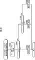
図1は、本発明の第1実施形態の空調装置のシステム構成の概略を示す図である。図外の車両に搭載された空調装置10は、空調装置10を操作するためのスイッチ操作部11と、空調装置10に関する情報を表示する表示部12とを備える。更に、空調装置10は、スイッチ操作部11の操作に応じて、空調装置10の作動や表示部12の表示を制御するCPU(Central Processing Unit:中央処理装置)13を備える。[First Embodiment]
FIG. 1 is a diagram showing an outline of the system configuration of the air conditioner according to the first embodiment of the present invention. An
表示部12は、点灯と消灯とを切り替え可能な小さなドットを並べ、このドットの点灯と消灯とによって文字や絵を表現できるドットマトリクス方式による表示が可能なカラー液晶画面で構成されている。また、表示部12は、赤,緑,青の3つの色の光の透過・非透過を切替自在なカラーフィルタを備えており、様々な色の表示が可能となっている。 The
また、車両には、各センサとして、車両の室内(車内)の湿度Hを検出する湿度センサ14と、車内の気温(内気温)Tiを検出する内気温センサ15と、車外の気温(外気温)Toを検出する外気温センサ16と、車両の走行速度(車速)Vを検出する車速センサ17と、車両の駆動源の冷却水の温度Twを検出する水温センサ18と、車内の送風口から送風される空気の温度(以下、「送風温」という)を検出する送風口温度センサ19と、冷風を送風するために空調装置10内の冷媒を冷却するエバポレータ(図示省略)の温度を検出するエバセンサ20を設けている。 In addition, the vehicle includes a
また、空調装置10は、空調装置10の作動を切り替えるためのアクチュエータとしての複数のモータ21を備える。この各アクチュエータ・モータ21は、例えば、送風口の切り替えを行なうモータ、冷たい空気及び暖かい空気を扉の開度を調整して混ぜることで送風する空気の温度を調整するエアミックス用のモータ、車内の空気を循環させる「内気循環」と車外の空気を車内に取り込む「外気循環」とを切り替えるモータなどで構成される。これらのモータ21が作動することで空調装置10の作動が切り替えられる。 The
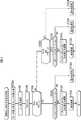
CPU13は、スイッチ操作部11の操作に対応した信号を送信するスイッチ入力部13aと、スイッチ入力部13aから送信された信号に基づいて空調装置10の空調の作動を処理する空調作動処理部13bとを備える。空調作動処理部13bは、表示制御部13cに対して、空調装置10に関する情報を表示部12に表示させるための信号を送信する。また、CPU13は、送風口からの送風温を算出した結果を空調作動処理部13bに信号として送信する送風口温度算出部13dと、各センサ14〜20の検出値を空調作動処理部13bに信号として送信するセンサ検出部13eと、各アクチュエータ・モータ21を作動させる信号を送信する駆動処理部13fとを備える。 The
このように空調作動処理部13bは、スイッチ入力部13a、送風口温度算出部13d及びセンサ検出部13eから送信された信号に基づいて、各アクチュエータ・モータ21を駆動処理部13fによって制御することで空調装置10を作動し、空調装置10に関する情報を表示部12に表示する。また、空調装置10は、CPU13で実行される各種演算プログラム、各種テーブル、演算結果などを記憶するROM及びRAMからなる記憶装置(図示省略)とを備える。 As described above, the air conditioning operation processing unit 13b controls each actuator / motor 21 by the
送風口温度算出部13dは、空調装置10の設定温度と各センサ14〜20の検出値とに基づいて、内気温センサ15によって検出される内気温が設定温度のときの送風温を算出する。送風口温度算出部13dによって算出される温度は、空調装置10の空調が冷房及び暖房のどちらでもなく安定動作中のときの送風温、換言すれば、設定温度に対して目標とする送風温である。内気温が設定温度のときでも、外気温センサによって検出される外気温が内気温よりも高い場合には、送風温を設定温度よりも多少低くするなどの制御が必要であり、そのときの状況に応じてこの目標とする送風温は変化する。このように、空調装置10からの送風温は、送風口温度算出部13dによって算出される温度になるように空調作動処理部13b及び駆動処理部13fによって制御される。 Based on the set temperature of the
スイッチ操作部11が本発明における操作部に相当し、CPU13が本発明における制御部に相当し、送風口温度算出部13dが本発明における送風温度算出部に相当する。また、湿度センサ14が本発明における車内湿度検出部に相当し、内気温センサ15が本発明における車内温度検出部に相当し、外気温センサ16が本発明における外気温検出部に相当し、送風口温度センサ19が本発明における送風温度検出部に相当する。 The
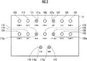
図2は、スイッチ操作部11の詳細を示す図である。図2に示す各スイッチ101〜116はプッシュ式のスイッチになっており、各スイッチ101〜116が操作されると、すなわち、スイッチが押下されると、この操作に対応した信号がスイッチ入力部13aに送信される。以下、空調作動処理部13bが、この送信された信号に基づいて実行する処理について説明する。 FIG. 2 is a diagram illustrating details of the
運転席設定温度上昇スイッチ(図2の右端に配置されたTEMP△スイッチ)101が操作されると運転席の設定温度を上昇させ、運転席設定温度下降スイッチ(図2の右端に配置されたTEMP▽スイッチ)102が操作されると運転席の設定温度を下降させる。助手席設定温度上昇スイッチ(図2の左端に配置されたTEMP△スイッチ)103が操作されると助手席の設定温度を上昇させ、助手席設定温度下降スイッチ(図2の左端に配置されたTEMP▽スイッチ)104が操作されると助手席の設定温度を下降させる。 When the driver's seat set temperature increase switch (TEMP switch arranged at the right end of FIG. 2) 101 is operated, the driver's seat set temperature rises, and the driver seat set temperature decrease switch (TEMP disposed at the right end of FIG. 2). When the ▽
A/Cスイッチ105が操作されると、空調装置10内の冷媒を圧縮するコンプレッサ(図示省略)を作動する「A/Cオン状態」にする。A/Cオン状態のときにA/Cスイッチ105が操作されると、コンプレッサの作動を停止する(A/Cオフ状態)。すなわち、A/Cスイッチ105によって、コンプレッサの作動及び非作動を手動(スイッチ操作)で変更できるように構成されている。 When the A /
また、MODEスイッチ106が操作されると、空調装置10の送風口が選択される。送風口は、運転席及び助手席の上半身に向けて送風する「上半身用」と、運転席及び助手席の足元に向けて送風する「足元用」と、上半身用の送風及び足元用の送風を同時に行なう「上半身+足元用」と、フロントガラスに向けて送風する「フロントガラス用」と、足元用及びフロントガラス用の送風を同時に行なう「足元+フロントガラス用」との5種類ある。MODEスイッチ106が操作される度に、「上半身用」→「上半身+足元用」→「足元用」→「足元+フロントガラス用」の順番で切り替える。 When the
DEFスイッチ107が操作されると、送風口を「フロントガラス用」にしてフロントガラスの霜取りを行なうフロント霜取りモードにする。フロント霜取りモードのときにDEFスイッチ107が操作されると、このモードを解除して、送風口の選択をフロント霜取りモードにする前の送風口に戻して、フロントガラスの霜取りを中止する。また、DEFスイッチ107には、LEDインジケータ107aが埋め込まれており、フロント霜取りモードのときに点灯し、フロント霜取りモードではないときに消灯する。 When the
リアDEFスイッチ108が操作されるとリアガラスの霜取りを行なうリア霜取りモードにする。リア霜取りモードのときにリアDEFスイッチ108が操作されると、このモードを解除して、リアガラスの霜取りを中止する。また、リアDEFスイッチ108には、LEDインジケータ108aが埋め込まれており、リア霜取りモードのときに点灯し、リア霜取りモードではないときに消灯する。 When the
FAN△スイッチ109が操作されると送風口から送風される空気の風量を上昇させ、FAN▽スイッチ110が操作されると送風口から送風される空気の風量を下降させる。 When the
SYNCスイッチ111が操作されると、助手席の設定温度を運転席の設定温度と同じ温度にする同期モードにする。また、同期モードのときにSYNCスイッチ111が操作されると、助手席の設定温度を同期モードにする前の設定温度に戻す。また、SYNCスイッチ111には、LEDインジケータ111aが埋め込まれており、同期モードのときに点灯し、同期モードではないときに消灯する。内気スイッチ112が操作されると、車内の空気を循環させる「内気循環」と車外の空気を車内に取り込む「外気循環」とを切り替える。また、内気スイッチ112には、LEDインジケータ112aが埋め込まれており、「内気循環」のときに点灯し、「外気循環」のときに消灯する。 When the
AUTOスイッチ113が操作されると、風量の設定、送風口の選択、A/Cオン状態又はA/Cオフ状態の選択、内気循環又は外気循環の選択を、各センサの検出値に応じて自動で設定する自動モードにする。OFFスイッチ114が操作されると、送風口から送風される空気の風量を0、すなわち、送風を停止する。 When the
湿度スイッチ115が操作されると、湿度センサ14によって検出された湿度Hを所定時間が経過するまで表示部12に表示する湿度表示モードにする。また、湿度表示モードのときに湿度スイッチ115が操作されると、湿度表示モードにする前に表示していた表示に戻す。また、湿度スイッチ115には、LEDインジケータ115aが埋め込まれており、湿度表示モードのときに点灯し、湿度表示モードではないときに消灯する。 When the
外気スイッチ116が操作されると、外気温センサ16によって検出された外気温Toを表示部12に表示する外気温表示モードにする。また、外気温表示モードのときに外気スイッチ116が操作されると、外気温表示モードにする前に表示していた表示に戻す。また、外気スイッチ116には、LEDインジケータ116aが埋め込まれており、外気温表示モードのときに点灯し、外気温表示モードではないときに消灯する。 When the
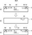
図3は、表示部12の詳細を示す図であり、図3(a)は、足元用の送風口が選択されている状態、図3(b)は、(a)の状態でMODEスイッチ106が操作された直後、図3(c)は、MODEスイッチ106が操作されてから所定時間経過した後の表示部12を示している。これらの表示は、空調作動処理部13bが表示制御部13cに信号を送信することで制御される。 3A and 3B are diagrams showing details of the
表示部12は、黒の背景に白で表示している(以下、この色を「通常の色」という)。図3(a)の運転席設定温度表示201は、運転席設定温度の上昇スイッチ101又は下降スイッチ102が操作されることで変化する運転席の設定温度を数字で表示している。助手席設定温度表示202は、助手席設定温度の上昇スイッチ103又は下降スイッチ104が操作されることで変化する助手席の設定温度を数字で表示している。 The
空調作動表示203は、A/Cスイッチ105が操作されることで変更されるコンプレッサの作動状態(「A/Cオン状態」又は「A/Cオフ状態」)を文字列で表示する。図3(a)は「A/Cオン状態」のときであり、「A/C ON」と表示される。「A/Cオフ状態」のときは、図3(a)に示す「A/C ON」という表示に代わり、「A/C OFF」と表示する。また、「A/Cオン状態」のときは、除湿中であるため、「A/C ON」の表示を緑色にし、除湿中であることの視認性を向上している。 The air
設定風量表示204は、FAN△スイッチ109又はFAN▽スイッチ110が操作されることで変化する送風口から送風される風量を図で表示している。送風口表示205は、MODEスイッチ106の操作によって選択されている送風口の種類を図で表示する。また、図3(a)には図示されていないが、フロント霜取りモード又はリア霜取りモードになっているときは、「DEF ON」又は「REARDEF ON」と表示し、同期モードになっているときは、「SYNC」と表示し、自動モードになっているときは、「AUTO」と表示してもよい。 The set
表示部12が図3(a)のように表示している状態で、MODEスイッチ106が操作されると、送風口を「足元用」から「足元+フロントガラス用」に切り替えるため、空調作動処理部13bは、表示部12の表示を図3(b)の表示に切り替える。すなわち、各表示201〜205を消し、MODEスイッチ106によって選択された送風口の種類に応じた表示を拡大して送風口強調表示205aを行なう。また、このときに、送風口強調表示205aは、他の表示とは異なる色が設定される。色の設定の詳細については、図6のフローチャートの説明で後述する。 When the
図3(b)の表示に切り替えてから所定時間が経過すると、空調作動処理部13bは、表示部12の表示を図3(c)の表示に切り替える。MODEスイッチ106の操作によって送風口の種類が変更されているため、図3(a)に示された表示と比べると、送風口表示205が現在の送風口の種類に変化している。 When a predetermined time elapses after switching to the display of FIG. 3B, the air conditioning operation processing unit 13b switches the display of the
図3では、MODEスイッチ106が操作されたときの例を示したが、空調装置10の作動状態と各操作スイッチ101〜116の操作とに応じて拡大される表示は変化する。例えば、図3(a)の状態で、運転席設定温度上昇スイッチ101が操作されると、現在の運転席の設定温度は25度から26度に変更される。このため、各表示201〜205を消し、「26」という数字を強調表示する。その後、所定時間が経過すると、消された各表示201〜205を再度表示する。このとき、設定温度が26度になったため、運転席設定温度表示201が「26」となる。 Although FIG. 3 shows an example when the
また、湿度スイッチ115又は外気スイッチ116が操作されると、上述したように、湿度H、外気温Toを表示部12に拡大して表示し、所定時間が経過すると、運転席設定温度表示201及び助手席温度表示202の表示部分に湿度H又は外気温Toを表示する。 When the
以下、図3(a),(c)に示す表示を通常表示、図3(b)に示す表示を強調表示という。図3(b)に例示するような強調表示が、本発明において、操作に対応する情報を拡大表示することに相当する。 Hereinafter, the display illustrated in FIGS. 3A and 3C is referred to as normal display, and the display illustrated in FIG. 3B is referred to as highlight display. The highlighted display as exemplified in FIG. 3B corresponds to the enlarged display of information corresponding to the operation in the present invention.
次に、本実施形態のCPU13によって実行される制御の処理について説明する。第1実施形態では、CPU13が、本発明における制御部及び送風温度算出部として動作する。 Next, control processing executed by the
図4は、CPU13が実行する本発明の表示処理の手順を示すフローチャートである。本フローチャートで示される制御処理プログラムは、所定時間(例えば、10msec)毎に呼び出されて実行される。 FIG. 4 is a flowchart showing the procedure of the display process of the present invention executed by the
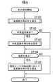
最初のステップST1は、表示用バッファのクリアを行なう。ここで、表示用バッファとは、表示部12に表示するための情報を格納する一時的なバッファである。空調作動処理部13bは、表示部12に表示する情報をこの表示用バッファに格納し、表示制御部13cに送信することで表示部12の表示が更新される。従って、ステップST1で表示用バッファをクリアしても表示制御部13cに送信していないため、表示部12の表示は変化しない。次に、ステップST2に進み、カウンタCの値を1増加する。 In the first step ST1, the display buffer is cleared. Here, the display buffer is a temporary buffer that stores information to be displayed on the
次にステップST3に進み、スイッチ操作部の各スイッチ101〜116のいずれかが操作されたか否かを判定する。判定結果がYESのときは、ステップST4に進み、この操作に対応した表示情報を表示用バッファに設定する。例えば、図3(b)のように、送風口として「足元用」が選択されているときに、MODEスイッチ106が操作されて「足元+フロントガラス用」を選択する場合には、選択されている送風口(送風口強調表示205a)を強調表示するように表示用バッファに設定する。 Next, it progresses to step ST3 and it is determined whether any of each switch 101-116 of a switch operation part was operated. When the determination result is YES, the process proceeds to step ST4, and the display information corresponding to this operation is set in the display buffer. For example, as shown in FIG. 3B, when “for foot” is selected as the air outlet, when the
次にステップST5に進み、表示部12に表示するときの色を設定する。この処理の詳細は、図6のフローチャートを用いて後述する。次にステップST6に進み、カウンタCの値を0にする。次にステップST7に進み、ステップST4,ST5で設定された表示用バッファの内容を表示制御部13cに送信し、表示部12の表示を更新する。 Next, proceeding to step ST5, a color for displaying on the
ステップST3の判定結果がNOのときは、ステップST8に進み、車速センサ17によって検出された車速Vに応じて表示時間閾値用カウンタCvの値を設定する。この設定は、図5に示される車速Vと表示時間との特性のように、車速Vが増加すると表示時間閾値用カウンタCvの値も増加するように設定する。 When the determination result in step ST3 is NO, the process proceeds to step ST8, and the value of the display time threshold counter Cv is set according to the vehicle speed V detected by the
図5は、横軸を車速V、縦軸を表示時間としており、車速Vが速度VLよりも小さいときは表示時間を0、車速Vが速度VL〜VHのときは表示時間をTL〜TH、車速Vが速度VHよりも大きいときは表示時間をTHとしている。速度VLは、表示時間が0、すなわち、図3(b)のような強調表示をしなくても運転に支障のない走行速度に設定される。通常は車速Vが0又は所謂徐行程度の速度に設定すればよい。 In FIG. 5, the horizontal axis represents the vehicle speed V and the vertical axis represents the display time. When the vehicle speed V is lower than the speed VL, the display time is 0. When the vehicle speed V is the speed VL to VH, the display time is TL to TH. When the vehicle speed V is higher than the speed VH, the display time is TH. The speed VL is set to a travel speed at which the display time is zero, that is, there is no hindrance to the driving without highlighting as shown in FIG. Usually, the vehicle speed V may be set to 0 or a so-called slow speed.
このように、速度が増加するに従って、表示時間を増加させることで、運転に支障を与えないタイミングで強調表示を確認できる可能性を高めている。速度VHよりも大きいときに表示時間をTHに固定しているのは、通常の表示に戻すまでの最大時間THを規定することで、いつまでも強調表示が続いてしまい、通常表示の情報を確認できなくなる事態を回避するためである。車速Vと表示時間とが図5に示されるような特性になるように、車速Vから表示時間を決定できるテーブルを予め作成しておき、記憶装置に記憶している。空調作動処理部13bは、このテーブルを参照して表示時間閾値用カウンタCvの値を設定する。 In this way, the display time is increased as the speed increases, thereby increasing the possibility that the highlighted display can be confirmed at a timing that does not hinder driving. The reason why the display time is fixed to TH when the speed is higher than the speed VH is that the maximum display time TH until the display is returned to the normal display is specified. This is to avoid the situation of disappearance. A table capable of determining the display time from the vehicle speed V is created in advance and stored in the storage device so that the vehicle speed V and the display time have characteristics as shown in FIG. The air conditioning operation processing unit 13b refers to this table and sets the value of the display time threshold counter Cv.
次にステップST9に進み、カウンタCの値が表示時間閾値用カウンタCvの値より大きいか否かを判定する。判定結果がNOのときは本処理を終了し、判定結果がYESのときはステップST10に進む。 Next, in step ST9, it is determined whether or not the value of the counter C is larger than the value of the display time threshold counter Cv. If the determination result is NO, the present process ends. If the determination result is YES, the process proceeds to step ST10.
ステップST10では、通常表示用の表示部12に表示する情報を表示用バッファに設定する。例えば、図3(a)のように表示する場合には、運転席の設定温度(運転席設定温度表示201)、助手席の設定温度(助手席設定温度表示202)、選択されている空調装置のコンプレッサの作動状態(空調作動表示203)、送風される空気の設定風量(設定風量表示204)、選択されている送風口(送風口表示205)を設定する。また、このときA/Cオン状態(空調作動表示203が「A/C ON」を表示しているとき)であるならば、上述したように除湿中であるため、空調作動表示203の色を緑色に設定する。 In step ST10, information to be displayed on the
次にステップST11に進み、ステップST10で設定された表示用バッファの内容を表示制御部13cに送信し、表示部12の表示を更新する。次にステップST12に進み、カウンタCに表示時間閾値用カウンタCvの値を設定する。このステップの処理によって、スイッチ操作部11の各スイッチ101〜116の操作が行なわれずに長い時間経過した場合に、図4の処理が定期的に実行され、ステップST2の処理によってカウンタCが増加し続け、オーバーフローなどによる誤作動が発生することを防止している。 In step ST11, the contents of the display buffer set in step ST10 are transmitted to the display control unit 13c, and the display on the
ステップST3の判定結果がYESのときに実行されるステップST4〜ST7の処理が強調表示のための処理となる。また、ステップST3の判定結果がNOのときに実行されるステップST10〜ST12の処理が通常表示のための処理となる。スイッチ操作部11の各スイッチ101〜116が操作されると0に設定されるカウンタCの値が、表示時間閾値用カウンタCvの値を超えたか否かを判定することが、本発明において、操作部が操作されてから所定の時間が経過したか否かを判定することに相当する。 The process of steps ST4 to ST7 executed when the determination result of step ST3 is YES is the process for highlighting. Further, the processing of steps ST10 to ST12 executed when the determination result of step ST3 is NO is the processing for normal display. In the present invention, it is determined whether or not the value of the counter C set to 0 exceeds the value of the display time threshold counter Cv when the
続いて、図6のフローチャートを用いてステップST5の色の設定をする処理の詳細について説明する。なお、「色の設定をする」とは、表示部12の表示に色が付くように、表示用バッファに設定することをいう。 Next, details of the process of setting the color in step ST5 will be described using the flowchart of FIG. “Setting the color” means setting the display buffer so that the display on the
最初のステップST101は、強調表示のときの色を設定する。この処理の詳細について図7を用いて説明する。図7のフローチャートの最初のステップST201は、送風口温度センサ19によって送風口検出温度Taを検出する。 In the first step ST101, a color for highlighting is set. Details of this processing will be described with reference to FIG. In the first step ST201 of the flowchart of FIG. 7, the air outlet temperature sensor 19 detects the air outlet detection temperature Ta.
次にステップST202に進み、空調装置の設定温度Tsを取得する。 Next, it progresses to step ST202 and the preset temperature Ts of an air conditioner is acquired.
次にステップST203に進み、送風口検出温度Taから設定温度Tsを引いた差分TDを求める。続いて、ステップST204に進み、差分TDが0より大きく、且つ差分TDの絶対値|TD|が所定の値α1より大きいか否かを判定する。差分TDが0より大きい場合は、実際の送風温(送風口検出温度Ta)が設定温度Tsより高い場合であり暖房動作中を示す。α1は0として設定してもよいし、実際の送風温が設定温度よりも高い場合に、暖房動作ではなく通常動作として扱える温度の差を設定してもよい。 Next, the process proceeds to step ST203, and a difference TD obtained by subtracting the set temperature Ts from the air outlet detection temperature Ta is obtained. Subsequently, the process proceeds to step ST204, in which it is determined whether or not the difference TD is greater than 0 and the absolute value | TD | of the difference TD is greater than a predetermined value α1. When the difference TD is greater than 0, the actual air temperature (air outlet detection temperature Ta) is higher than the set temperature Ts, indicating that the heating operation is being performed. α1 may be set as 0, or when the actual blown air temperature is higher than the set temperature, a temperature difference that can be handled as a normal operation instead of a heating operation may be set.
ステップST204の判定結果がYESのときは、ステップST205に進み、温風を送風するために空気を暖めるためのヒータコアが暖まっていないか否かを判定する。ヒータコアには、車両の駆動源の冷却水が流れている。このため、駆動源の冷却水の温度Twを水温センサ18で検出し、予め定めた所定の温度以上のときにはヒータコアが暖まっていると判定し(ステップST205の判定結果がNO)、駆動源の冷却水の温度Twが、予め定めた所定の温度未満のときにはヒータコアが暖まっていないと判定する(ステップST205の判定結果がYES)。 When the determination result in step ST204 is YES, the process proceeds to step ST205, in which it is determined whether or not the heater core for warming air to blow warm air is not warmed. Cooling water from the vehicle drive source flows through the heater core. For this reason, the temperature Tw of the cooling water of the drive source is detected by the water temperature sensor 18, and when the temperature is equal to or higher than a predetermined temperature, it is determined that the heater core is warm (the determination result of step ST205 is NO). When the water temperature Tw is lower than a predetermined temperature, it is determined that the heater core is not warmed (the determination result in step ST205 is YES).
ステップST205の判定結果がYESのときは、ステップST206に進み、通常の色(白)を設定する。ステップST205の判定結果がNOのときは、ステップST207に進み、差分TDの絶対値の大きさに応じて色の濃さを調整し、ステップST208に進み、暖色系の色(例えば、赤)を設定する。例えば、ステップST207,ST208で暖色系として赤を設定するならば、差分TDの絶対値の大きさが大きくなるに従い、濃い赤色になるように設定する。 If the decision result in the step ST205 is YES, the process proceeds to a step ST206 to set a normal color (white). If the decision result in the step ST205 is NO, the process advances to a step ST207 to adjust the color intensity according to the magnitude of the absolute value of the difference TD, and the process advances to a step ST208 to select a warm color (for example, red). Set. For example, if red is set as the warm color system in steps ST207 and ST208, the red color is set to become darker as the absolute value of the difference TD increases.
ステップST204の判定結果がNOのときは、ステップST209に進み、差分TDが0より小さく、且つ差分TDの絶対値|TD|が所定の値α2より大きいか否かを判定する。差分TDが0より小さい場合は、実際の送風温(送風口検出温度Ta)が設定温度Tsより低い場合であり冷房動作中を示す。α2は0として設定してもよいし、実際の送風温が設定温度Tsよりも低い場合に、冷房動作ではなく通常動作として扱える温度の差を設定してもよい。 If the decision result in the step ST204 is NO, the process advances to a step ST209 to determine whether or not the difference TD is smaller than 0 and the absolute value | TD | of the difference TD is larger than a predetermined value α2. When the difference TD is smaller than 0, the actual blowing temperature (the blowing port detection temperature Ta) is lower than the set temperature Ts, indicating that the cooling operation is being performed. α2 may be set as 0, or when the actual blowing temperature is lower than the set temperature Ts, a temperature difference that can be handled as a normal operation instead of a cooling operation may be set.
ステップST209の判定結果がYESのときは、ステップST210に進み、冷風を送風するために空気を冷やすためのエバポレータが冷えていないか否かを判定する。これは、エバセンサ20が検出したエバポレータの温度が予め定めた所定の温度以下のときにエバポレータが冷えていると判定し(ステップST210の判定結果がNO)、エバセンサ20が検出した温度が予め定めた所定の温度より大きいときにエバポレータが冷えていないと判定する(ステップST210の判定結果がYES)。 When the determination result in step ST209 is YES, the process proceeds to step ST210, in which it is determined whether or not the evaporator for cooling the air to cool the air is not cooled. It is determined that the evaporator is cold when the temperature of the evaporator detected by the
ステップST210の判定結果がYESのときは、ステップST211に進み、通常の色(白)を設定する。ステップST210の判定結果がNOのときは、ステップST212に進み、差分TDの絶対値の大きさに応じて色の濃さを調整し、ステップST213に進み、寒色系の色(例えば、青)を設定する。例えば、ステップST212,ST213で寒色系として青を設定するならば、差分TDの絶対値の大きさが大きくなるに従い、濃い青色になるように設定する。 If the decision result in the step ST210 is YES, the process proceeds to a step ST211 to set a normal color (white). When the determination result in step ST210 is NO, the process proceeds to step ST212, the color intensity is adjusted according to the absolute value of the difference TD, and the process proceeds to step ST213, where a cold color (for example, blue) is selected. Set. For example, if blue is set as the cold color system in steps ST212 and ST213, the blue color is set to become dark blue as the absolute value of the difference TD increases.
ステップST209の判定結果がNOのときは、ステップST214に進み、通常の色(白)を設定する。ステップST206,ST208,ST211,ST213又はST214の処理が終了すると、図7の処理を終了し、図6のステップST102に進む。 If the decision result in the step ST209 is NO, the process proceeds to a step ST214 to set a normal color (white). When the process of step ST206, ST208, ST211, ST213, or ST214 is completed, the process of FIG. 7 is terminated, and the process proceeds to step ST102 of FIG.
ステップST102では、外気スイッチ116が操作されることで外気温Toを表示する必要が生じたか否かを判定する。判定結果がYESのときは、ステップST103に進み、外気温Toを表示するときの色を設定する。 In step ST102, it is determined whether or not it is necessary to display the outside air temperature To by operating the
図8を用いてステップST103の詳細な処理について説明する。図8のフローチャートの最初のステップST301は、外気温センサ16によって外気温Toを検出する。次に、ステップST302に進み、外気温Toが所定の値β1未満か否かを判定する。ステップST302の判定結果がYESのときは、ステップST303に進み、寒色系の色(例えば、青)に設定し、NOのときは、ステップST304に進む。 The detailed process of step ST103 will be described with reference to FIG. In the first step ST301 in the flowchart of FIG. 8, the outside air temperature To is detected by the outside
ステップST304では、外気温Toが所定の値β2未満か否かを判定する。ステップST304の判定結果がYESのときは、ステップST305に進み、通常の色(白)に設定し、NOのときは、ステップST306に進み、暖色系の色(例えば、赤)に設定する。 In step ST304, it is determined whether or not the outside air temperature To is less than a predetermined value β2. If the determination result in step ST304 is YES, the process proceeds to step ST305, where a normal color (white) is set. If NO, the process proceeds to step ST306, where a warm color (for example, red) is set.
β1及びβ2は、外気温Toが、寒い気温(ステップST302の判定結果がYES)、程よい気温(ステップST304の判定結果がYES)、又は暑い気温(ステップST304の判定結果がNO)のいずれであるかを適切に判別可能に設定されていればよい。 In β1 and β2, the outside air temperature To is either a cold air temperature (the determination result in step ST302 is YES), a moderate air temperature (the determination result in step ST304 is YES), or a hot air temperature (the determination result in step ST304 is NO). It is only necessary to be set so that it can be properly determined.
ステップST303,ST305又はST306の処理が終了するか、図6のステップST102の判定結果がNOのときは、ステップST104に進み、湿度スイッチ115が操作されることで湿度Hを表示する必要が生じたか否かを判定する。判定結果がYESのときは、ステップST105に進み、湿度センサ14の検出値である湿度Hに応じて湿度表示用の色を設定する。これは、湿度Hが増加するに従って、緑色が濃くなるように設定する。色の濃さを変更するだけではなく、ステップST103の外気温Toのときのように閾値を設定して、色を変更してもよい。 When the process of step ST303, ST305 or ST306 is completed, or when the determination result of step ST102 of FIG. 6 is NO, the process proceeds to step ST104, where it is necessary to display humidity H by operating the
ステップST103又はST105による色の設定では、ステップST101の色の設定が上書きされる。但し、ステップST101で強調表示のために背景の色を変更しており、ステップST103又はST105で背景の色を変更していない場合には、強調表示の背景の色は、ST101で設定された背景の色となる。すなわち、このような場合には、ステップST101で設定した背景の色に関しては上書きされない。 In the color setting in step ST103 or ST105, the color setting in step ST101 is overwritten. However, if the background color is changed for highlighting in step ST101 and the background color is not changed in step ST103 or ST105, the background color of highlighting is the background set in ST101. It becomes the color. That is, in such a case, the background color set in step ST101 is not overwritten.
ステップST105の処理が終了すると、前述の図4のステップST6に進む。 When the process of step ST105 ends, the process proceeds to step ST6 of FIG.
以上のように、操作部としてのスイッチ操作部11の各スイッチ101〜116が操作されると、ステップST4,5,6及び7の処理によって、表示部12の表示がこの操作に対応した表示になるように表示用バッファに設定される。そして、各スイッチ101〜116が操作されてカウンタCの値が0に設定されてから(ステップST6)、このカウンタCの値が表示時間閾値用カウンタCvの値を超えるまでは(ステップST9の判定結果がYESになるまでは)、表示部12の表示が図3(b)に例示するような強調表示に変更され、カウンタCの値が表示時間閾値用カウンタCvの値を超えた後は(ステップST9の判定結果がYESになったとき)、表示部12の表示が図3(a),(c)に例示するような通常表示に変更される。 As described above, when each of the
従って、操作部としてのスイッチ操作部11の操作に対応した情報が強調表示されると共に、スイッチ操作部11の操作に対応しない情報の表示は消されるため、表示部12の操作に対応する情報の表示の視認性を向上することができる。 Accordingly, the information corresponding to the operation of the
また、表示部12は、従来から使用されているドットマトリクス方式による表示が可能なカラー液晶画面であるため、従来の機能を有したまま、本発明の効果である視認性の向上を実現できる。 In addition, since the
また、図7に示されるフローチャートの処理によって、送風口温度センサ19の検出値である送風口検出温度Taと空調装置10の設定温度Tsとから強調表示の色を設定している。これは、前記第3発明における空調装置の設定温度と送風温度検出部によって検出された温度との差に応じた色で、操作に対応する情報を表示することに相当する。 Further, by the processing of the flowchart shown in FIG. 7, the highlighted color is set from the air outlet detection temperature Ta, which is a detection value of the air outlet temperature sensor 19, and the set temperature Ts of the
これによって、設定温度に対する空調装置10の現在の作動が暖房動作中、冷房動作中、安定動作中のいずれであるかを色で識別することができる。このため、暖房動作中、冷房動作中、安定動作中のいずれであるかを確認するために、文字や図形を識別する必要がなくなり、空調装置10の作動状態の視認性を向上させることができる。 Accordingly, it is possible to identify by color whether the current operation of the
特に、暖房動作中のときに暖色系を設定し、冷房動作中のときに寒色系を設定することで、温度に対する色の感覚に合い、より視認性を向上させることができる。 In particular, by setting the warm color system during the heating operation and setting the cold color system during the cooling operation, the visibility can be further improved in accordance with the sense of color with respect to the temperature.
また、除湿中は、空調作動表示203を緑色に設定して表示している。これは、前記第6発明における除湿を行なっている場合には、除湿を行なっていない場合と異なる色で、操作に対応する情報を表示することに相当する。これによって、除湿中であることを色で識別することができるため、除湿中か否かの表示の視認性を向上させることができる。 During dehumidification, the air
また、外気温Toを表示するとき(ステップST102の判定結果がYESのとき)は、外気温センサ16の検出値に応じて色を設定している。これは、前記第7発明における表示部に外気温を表示するときには、外気温検出部が検出した温度に応じた色で、操作に対応する情報を表示することに相当する。 Further, when the outside air temperature To is displayed (when the determination result in step ST102 is YES), the color is set according to the detected value of the outside
これによって、外気温Toの高低を色で識別することができるため、外気温Toの表示に関して視認性を向上させることができる。特に、外気温Toが高いときに暖色系を設定し、外気温Toが低いときに寒色系を設定することで、温度に対する色の感覚に合い、より視認性を向上させることができる。 As a result, the level of the outside air temperature To can be identified by color, so that the visibility regarding the display of the outside air temperature To can be improved. In particular, by setting a warm color system when the outside air temperature To is high and setting a cold color system when the outside air temperature To is low, the color perception with respect to temperature can be matched and the visibility can be further improved.
また、湿度Hを表示するとき(ステップST104の判定結果がYESのとき)は、湿度センサ14の検出値に応じて色を設定している。これは、前記第8発明における表示部に湿度を表示するときには、車内湿度検出部が検出した湿度に応じた色で、操作に対応する情報を表示することに相当する。これによって、湿度Hの高低を色で識別することができるため、湿度Hの表示に関して視認性を向上させることができる。 Further, when the humidity H is displayed (when the determination result of step ST104 is YES), the color is set according to the detection value of the
また、ステップST8で、表示時間閾値用カウンタCvの値を車速センサ17によって検出された車速Vが増加すると増加するように設定している。これは、前記第9発明における所定の時間は、車両の走行速度の増加に応じて増加することに相当する。これによって、高速度で運転中であっても、運転に支障を与えないタイミングで強調表示を確認できる可能性を高めることができる。 In step ST8, the value of the display time threshold counter Cv is set to increase as the vehicle speed V detected by the
尚、第1実施形態では、図7のフローチャートにおいて、ステップST201で検出した送風口温度センサの検出値Taと、ステップST202で取得した空調装置10の設定温度Tsとの差分TDをステップST203で求めている。ステップST201の処理は、空調装置10の設定温度Tsを取得する以外の処理でもよく、例えば、内気温センサ15によって内気温Tiを検出してもよい。この場合には、ステップST203で、空調装置10の設定温度Tsと内気温センサ15の検出値の内気温Tiとの差によって差分TDを求めればよい。これによって、設定温度Tsに対する実際の内気温Tiの高低を色で識別することができる。 In the first embodiment, in the flowchart of FIG. 7, the difference TD between the detected value Ta of the air outlet temperature sensor detected in step ST201 and the set temperature Ts of the
これは、第3発明における、空調装置の設定温度と、車内温度検出部によって検出された温度との差に応じた色で、操作に対応する情報を表示することに相当する。 This is equivalent to displaying information corresponding to the operation with a color according to the difference between the set temperature of the air conditioner and the temperature detected by the in-vehicle temperature detection unit in the third invention.
更に、ステップST201の処理としては、CPU13の送風口温度算出部13dによって送風温を算出してもよい。この場合には、ステップST203で、空調装置10の設定温度Tsと送風口温度算出部13dによって算出された送風温との差によって差分TDを求めればよい。これによっても、設定温度Tsに対する送風温の高低を色で識別することができる。 Furthermore, as a process of step ST201, the air blowing temperature may be calculated by the air outlet
これは、第3発明における、空調装置の設定温度と、送風温度算出部によって算出された温度との差に応じた色で、操作に対応する情報を表示することに相当する。 This is equivalent to displaying information corresponding to the operation with a color corresponding to the difference between the set temperature of the air conditioner and the temperature calculated by the blower temperature calculation unit in the third invention.
また、第1実施形態では、背景を黒、通常の色を白、暖色系の色を赤、寒色系の色を青としているが、視認性を低下させるような色でなければ他の色であってもよい。また、第1実施形態では、ステップST208で暖色系、ステップST213で寒色系、ステップST206,ST211,ST214で通常の色を設定しているが、暖房動作中、冷房動作中、安定動作中(暖房動作中、冷房動作中のいずれでもない動作のとき)のいずれであるかの判別が容易な色に設定されればよい。外気温Toを表示するときも同様に、外気温Toの高低を判別が容易であれば、暖色系、寒色系の色ではなくてもよい。 In the first embodiment, the background is black, the normal color is white, the warm color is red, and the cold color is blue. There may be. In the first embodiment, a warm color system is set in step ST208, a cold color system is set in step ST213, and a normal color is set in steps ST206, ST211, and ST214. However, during the heating operation, the cooling operation, and the stable operation (heating) It is only necessary to set the color so that it can be easily determined whether the operation is an operation or an operation other than the cooling operation. Similarly, when the outside temperature To is displayed, the color may not be a warm color or a cold color as long as it is easy to determine the level of the outside temperature To.
また、第1実施形態では、除湿時に空調作動表示203を緑色で表示するように設定しているが、緑色ではなくてもよい。除湿しているときと除湿していないときとの判別が容易であればよい。また、湿度Hを表示するときに、湿度Hに応じて緑色の濃さを設定しているが、緑色ではなくてもよい。また、湿度Hに応じて濃さを変更するのではなく、いくつかの閾値を設定して閾値ごとに暖色系、寒色系のように色を変更してもよい。 In the first embodiment, the air
また、図7のフローチャートにおいて、ヒータコアが暖まっていないとき(ステップST205の判定結果がYESのとき)又はエバポレータが冷えていないとき(ステップST210の判定結果がYESのとき)には、ステップST206又はST211において通常の色を設定している。空調装置10がこれらの状態にあるときは、空調機能を充分に発揮できないときである。これを通知するために、通常の色、暖色及び寒色のいずれでもない色を設定してもよい。これによって、空調が充分に働けない状態であることを色で通知することができる。 In the flowchart of FIG. 7, when the heater core is not warmed (when the determination result of step ST205 is YES) or when the evaporator is not cooled (when the determination result of step ST210 is YES), step ST206 or ST211 is performed. The normal color is set in. When the
また、第1実施形態では、表示部12は、カラーフィルタを有するドットマトリクス方式による表示が可能なカラー液晶画面で構成されているが、この構成に限らず、強調表示や色を設定可能な表示装置であればよい。 In the first embodiment, the
例えば、カラーフィルタを用いずに赤、緑、青の3色のLEDバックライトの点灯時間をずらして色を表現するFSLCD(Filed Sequencial Liquid Crystal Display)、又は電圧の供給によって発光するカラー有機EL(Electro-Luminescence)ディスプレイであってもよい。 For example, FSLCD (Filed Sequencial Liquid Crystal Display) that expresses colors by shifting the lighting time of LED backlights of three colors, red, green, and blue without using color filters, or color organic EL that emits light by supplying voltage ( Electro-Luminescence) display may be used.
この場合であっても、スイッチ操作部11の操作に対応する情報が強調表示され、スイッチ操作部11の操作に対応しない情報の表示は消されるため、本発明の効果として、表示部12の操作に対応する情報の表示の視認性を向上することができる。 Even in this case, the information corresponding to the operation of the
また、表示部12は、強調表示が可能であれば色が設定できなくてもよい。この場合には、ステップST4の処理が終了した後に、ステップST5の処理をせずに、ステップST6の処理を実行すればよい。この場合であっても、スイッチ操作部11の操作に対応する情報が強調表示され、スイッチ操作部11の操作に対応しない情報の表示は消されるため、本発明の効果として、表示部12の操作に対応する情報の表示の視認性を向上することができる。 The
[第2実施形態]
次に、本発明の第2実施形態の空調装置について説明する。第2実施形態の空調装置10は、表示部12が、表示する絵や文字に合わせて予め形状が決定されたセグメント毎に点灯と消灯とを切り替え可能なセグメント方式による表示が可能なカラー液晶画面で構成されている。また、第1実施形態と同様に、表示部12は、赤,緑,青の3つの色の光の透過・非透過を切替自在なカラーフィルタを備えており、様々な色の表示が可能となっている。その他の構成は第1実施形態と同じであるため、説明を省略する。尚、第1実施形態と同様に、表示部12は、FSLCD又はカラー有機ELディスプレイで構成されていてもよい。[Second Embodiment]
Next, an air conditioner according to a second embodiment of the present invention will be described. The
図9は、表示部12の詳細を示す図であり、図9(a)は、足元用の送風口が選択されている状態、図9(b)は、(a)の状態でMODEスイッチ106が操作された直後、図9(c)は、MODEスイッチ106が操作されてから所定時間経過した後の表示部12を示している。これらの表示は、第1実施形態と同様に、空調作動処理部13bが表示制御部13cに信号を送信することで制御される。 FIG. 9 is a diagram showing details of the
表示部12は、第1実施形態と同様に、黒の背景に白で表示している。図9(a)の運転席設定温度表示301,助手席設定温度表示302は、第1実施形態の運転席設定温度表示201,助手席設定温度表示202と同様に、運転席,助手席の設定温度を数字で表示している。 The
空調作動表示303は、A/Cスイッチ105が操作されることで変更されるコンプレッサの作動状態(「A/Cオン状態」又は「A/Cオフ状態」)を文字列で表示する。図9(a)は「A/Cオン状態」のときであり、「A/C ON」と表示される。「A/Cオフ状態」のときは、図3(a)に示す「A/C ON」という表示に代わり、「A/C OFF」と表示する。また、「A/Cオン状態」のときは、除湿中であるため、「A/C ON」の表示を緑色にし、除湿中であることの視認性を向上している。 The air
設定風量表示304は、FAN△スイッチ109又はFAN▽スイッチ110が操作されることで変化する送風口から送風される風量を図で表示している。送風口表示305は、MODEスイッチ106の操作によって選択されている送風口の種類を図で表示する。また、図9(a)には図示されていないが、フロント霜取りモード又はリア霜取りモードになっているときは、「DEF ON」又は「REARDEF ON」と表示し、同期モードになっているときは、「SYNC」と表示し、自動モードになっているときは、「AUTO」と表示してもよい。また、第1実施形態と同様に、4つのLEDインジケータ107a,108a,111a,112aは、点灯又は消灯によって空調装置10の作動状態を通知する。 The set
表示部12が図9(a)のように表示している状態で、MODEスイッチ106が操作されると、送風口を「足元用」から「足元+フロントガラス用」に切り替えるため、空調作動処理部13bは、表示部12の表示を図9(b)の表示に切り替える。すなわち、各表示301〜304を消し、MODEスイッチ106によって選択された送風口の種類に応じた表示305のみを表示する。また、このときに、送風口表示305は、第1実施形態と同様に、他の表示とは異なる色が設定される。 When the
図9(b)の表示に切り替えてから所定時間が経過すると、空調作動処理部13bは、表示部12の表示を図9(c)の表示に切り替える。MODEスイッチ106の操作によって送風口の種類が変更されているため、図9(a)に示された表示と比べると、送風口表示305が現在の送風口の種類に変化している。 When a predetermined time elapses after switching to the display of FIG. 9B, the air conditioning operation processing unit 13b switches the display of the
図9では、MODEスイッチ106が操作されたときの例を示したが、第1実施形態と同様に、空調装置10の作動状態と各操作スイッチ101〜116の操作とに応じて表示は変化する。 Although FIG. 9 shows an example when the
以下、第2実施形態では、図9(a),(c)に示す表示を通常表示、図9(b)に示す表示を強調表示という。図9(b)に例示するような強調表示が、本発明において、操作に対応する情報を表示し、操作に対応しない情報の表示を消すことに相当する。 Hereinafter, in the second embodiment, the display illustrated in FIGS. 9A and 9C is referred to as normal display, and the display illustrated in FIG. 9B is referred to as highlight display. The highlighted display as illustrated in FIG. 9B corresponds to displaying information corresponding to an operation and erasing display of information not corresponding to the operation in the present invention.
第2実施形態においても、制御部としてのCPU13は、第1実施形態と同様に、図4及び図6〜8の処理によって、空調装置10の制御を実行する。 Also in 2nd Embodiment, CPU13 as a control part performs control of the
以上のように構成された空調装置10は、操作部としてのスイッチ操作部11の各スイッチ101〜116が操作されると、表示部12の表示が、この操作に対応した表示、すなわち、図9(b)に例示するような強調表示に変更される。そして、第1実施形態と同様に、所定時間が経過すると、すなわち、カウンタCの値が表示時間閾値用カウンタCvの値を超えると、表示部12の表示が図9(c)に例示するような通常表示に変更される。従って、操作部としてのスイッチ操作部11の表示部12の操作に対応する情報の表示の視認性を向上することができる。 In the
また、表示部12は、従来から使用されているセグメント方式による表示が可能なカラー液晶画面であるため、従来の機能を有したまま、本発明の効果である視認性の向上を実現できる。 In addition, since the
また、第2実施形態では、表示部12をセグメント方式による表示が可能に構成しているため、表示部12をドットマトリクス方式による表示が可能な液晶画面で構成する場合に比べて、安価に構成できると共に、表示部12に表示するための制御の処理を簡潔にできる。 Further, in the second embodiment, since the
また、第1実施形態のドットマトリクス方式によって得られる効果、すなわち、拡大して表示することで視認性を向上できる効果以外の効果に関しては、第2実施形態でも同様に得ることができる。 Further, effects other than the effect obtained by the dot matrix method of the first embodiment, that is, the effect of improving the visibility by enlarging the display, can be similarly obtained in the second embodiment.
[第3実施形態]
次に、本発明の第3実施形態の空調装置について説明する。第3実施形態の空調装置10は、第1実施形態の空調装置10と比べて、図6のステップST101の強調表示用の色の設定をする処理が異なる。これについて、図10を用いて説明する。[Third Embodiment]
Next, an air conditioner according to a third embodiment of the present invention will be described. The
ステップST401は、内気温センサ15によって内気温Tiを検出する。次にステップST402に進み、内気温Tiが所定の値γ1未満か否かを判定する。ステップST402の判定結果がYESのときは、ステップST403に進み、寒色系の色(例えば、青)を設定し、ステップST402の判定結果がNOのときは、ステップST404に進む。 In step ST401, the
ステップST404では、内気温Tiが所定の値γ2未満か否かを判定する。ステップST404の判定結果がYESのときは、ステップST405に進み、通常の色を設定し、ステップST404の判定結果がNOのときは、ステップST406に進み、暖色系の色(例えば、赤)を設定する。 In step ST404, it is determined whether the internal temperature Ti is less than a predetermined value γ2. If the determination result in step ST404 is YES, the process proceeds to step ST405, where a normal color is set. If the determination result in step ST404 is NO, the process proceeds to step ST406, where a warm color (for example, red) is set. To do.
γ1及びγ2は、内気温Tiが、寒い気温(ステップST402の判定結果がYES)、程よい気温(ステップST404の判定結果がYES)、又は暑い気温(ステップST404の判定結果がNO)のいずれであるかを適切に判別可能に設定されていればよい。 In γ1 and γ2, the internal temperature Ti is either a cold temperature (the determination result of step ST402 is YES), a moderate temperature (the determination result of step ST404 is YES), or a hot temperature (the determination result of step ST404 is NO). It is only necessary to be set so that it can be properly determined.
ステップST403,ST405,ST406の処理が終了すると、図6のステップST102の処理を実行する。他の処理に関しては第1実施形態と同じであるため省略する。 When the processes of steps ST403, ST405, and ST406 are completed, the process of step ST102 of FIG. 6 is executed. Since other processes are the same as those in the first embodiment, the description thereof is omitted.
以上のように構成された空調装置10は、操作部としてのスイッチ操作部11の各スイッチ101〜116が操作されたときの強調表示のときに、内気温センサ15の検出値である内気温Tiに応じて色を変化させる。このため、強調表示することによる視認性の向上と共に、車内の温度の表示に関して、視認性を向上することができる。 The
また、第1実施形態と同様に、表示部12は、従来から使用されているドットマトリクス方式による表示が可能なカラー液晶画面であるため、従来の機能を有したまま、本発明の効果である視認性の向上を実現できる。 Similarly to the first embodiment, the
特に、内気温Tiが高いときに暖色系を設定し、内気温Tiが低いときに寒色系を設定することで、温度に対する色の感覚に合い、より視認性を向上させることができる。 In particular, the warm color system is set when the internal temperature Ti is high, and the cold color system is set when the internal temperature Ti is low.
尚、ステップST403,ST406のときには、内気温Tiの大きさに応じて色の濃さを変更して設定してもよい。例えば、ステップST403において、内気温Tiとγ1との差分の大きさが大きくなるほど青の濃さを濃くし、ステップST406において、内気温Tiとγ2との差分の大きさが大きくなるほど赤の濃さを濃くする。これによって、内気温Tiのより細かい識別を、色によって行なうことができ、内気温Tiの表示に関して、更に視認性が向上する。 In steps ST403 and ST406, the color intensity may be changed and set according to the size of the internal temperature Ti. For example, in step ST403, the greater the difference between the internal temperature Ti and γ1, the darker the blue, and in step ST406, the greater the difference between the internal temperature Ti and γ2, the greater the redness. To darken. Thereby, the finer identification of the internal temperature Ti can be performed by color, and the visibility of the display of the internal temperature Ti is further improved.
また、図10の処理を、内気温センサ15の検出値である内気温Tiではなく、空調装置10の設定温度で行なってもよい。この場合には、図10中の内気温Tiを設定温度に置き換えて処理する。設定温度は、運転席の設定温度でもよいし、運転席の設定温度と助手席の設定温度との平均値、最小値又は最大値でもよい。このとき、設定温度の大きさに応じて色の濃さを変更するとよい。 Moreover, you may perform the process of FIG. 10 with the preset temperature of the
これによって、設定温度の高低を色で把握することができ、設定温度の表示に関して、視認性を向上できる。このとき、第2実施形態のように、表示部12がセグメント方式による表示が可能に構成されていてもよい。 As a result, the level of the set temperature can be grasped by color, and the visibility of the set temperature display can be improved. At this time, as in the second embodiment, the
10…空調装置、11…スイッチ操作部(操作部)、12…表示部、13…CPU(制御部)、13d…送風口温度算出部(送風温度算出部)、14…湿度センサ(車内湿度検出部)、15…内気温センサ(車内温度検出部)、16…外気温センサ(外気温検出部)、19…送風口温度センサ(送風温度検出部)。 DESCRIPTION OF
Claims (9)
Translated fromJapanese当該空調装置に関する情報を表示する表示部と、
前記操作部の操作に応じて前記表示部の表示を制御する制御部とを備え、
前記制御部は、前記操作部が操作されてから所定の時間が経過するまで、前記操作に対応する情報を表示し、前記操作に対応しない情報の表示を消すことを特徴とする車両用空調装置。An operation unit for operating an air conditioner mounted on the vehicle;
A display unit for displaying information about the air conditioner;
A control unit that controls display of the display unit according to an operation of the operation unit,
The control unit displays information corresponding to the operation until a predetermined time elapses after the operation unit is operated, and turns off the display of information not corresponding to the operation. .
当該車両には、当該車両の室内の温度を検出する車内温度検出部と、当該空調装置から送風される空気の温度を検出する送風温度検出部とが設けられ、
前記制御部は、前記車内温度検出部によって検出される温度が当該空調装置の設定温度になるように制御するために、前記車内温度検出部によって検出された温度及び前記設定温度に基づいて当該空調装置から送風される空気の温度を算出する送風温度算出部とを備え、
当該空調装置の設定温度と、前記送風温度検出部によって検出された温度、前記送風温度算出部によって算出された温度、又は前記車内温度検出部によって検出された温度との差に応じた色で、前記操作に対応する情報を表示することを特徴とする空調装置。In the air conditioner according to claim 1 or 2,
The vehicle is provided with an in-vehicle temperature detection unit that detects a temperature inside the vehicle and a blowing temperature detection unit that detects the temperature of air blown from the air conditioner,
The control unit controls the air conditioning based on the temperature detected by the vehicle interior temperature detection unit and the set temperature in order to control the temperature detected by the vehicle interior temperature detection unit to be a set temperature of the air conditioning apparatus. A blowing temperature calculation unit for calculating the temperature of air blown from the device,
In a color according to the difference between the set temperature of the air conditioner and the temperature detected by the air temperature detector, the temperature calculated by the air temperature calculator, or the temperature detected by the in-vehicle temperature detector, An air conditioner that displays information corresponding to the operation.
当該車両には、当該車両の室内の温度を検出する車内温度検出部が設けられ、
前記制御部は、前記車内温度検出部が検出した温度に応じた色で、前記操作に対応する情報を表示することを特徴とする空調装置。In the air conditioner according to claim 1 or 2,
The vehicle is provided with an in-vehicle temperature detection unit that detects the temperature inside the vehicle,
The said control part displays the information corresponding to the said operation with the color according to the temperature which the said vehicle interior temperature detection part detected, The air conditioner characterized by the above-mentioned.
当該車両には、外気温を検出する外気温検出部が設けられ、
前記制御部は、前記表示部に前記外気温を表示するときには、前記外気温検出部が検出した温度に応じた色で、前記操作に対応する情報を表示することを特徴とする空調装置。The air conditioner according to any one of claims 1 to 6,
The vehicle is provided with an outside air temperature detection unit for detecting outside air temperature,
When the control unit displays the outside air temperature on the display unit, the control unit displays information corresponding to the operation in a color corresponding to the temperature detected by the outside air temperature detection unit.
当該車両には、当該車両の室内の湿度を検出する車内湿度検出部が設けられ、
前記制御部は、前記表示部に前記湿度を表示するときには、前記車内湿度検出部が検出した湿度に応じた色で、前記操作に対応する情報を表示することを特徴とする空調装置。In the air conditioner according to any one of claims 1 to 7,
The vehicle is provided with an in-vehicle humidity detection unit that detects the humidity inside the vehicle,
The control unit displays the information corresponding to the operation in a color corresponding to the humidity detected by the in-vehicle humidity detection unit when the humidity is displayed on the display unit.
Priority Applications (1)
| Application Number | Priority Date | Filing Date | Title |
|---|---|---|---|
| JP2010236517AJP5687470B2 (en) | 2010-10-21 | 2010-10-21 | Air conditioner for vehicles |
Applications Claiming Priority (1)
| Application Number | Priority Date | Filing Date | Title |
|---|---|---|---|
| JP2010236517AJP5687470B2 (en) | 2010-10-21 | 2010-10-21 | Air conditioner for vehicles |
Publications (2)
| Publication Number | Publication Date |
|---|---|
| JP2012086736Atrue JP2012086736A (en) | 2012-05-10 |
| JP5687470B2 JP5687470B2 (en) | 2015-03-18 |
Family
ID=46258825
Family Applications (1)
| Application Number | Title | Priority Date | Filing Date |
|---|---|---|---|
| JP2010236517AActiveJP5687470B2 (en) | 2010-10-21 | 2010-10-21 | Air conditioner for vehicles |
Country Status (1)
| Country | Link |
|---|---|
| JP (1) | JP5687470B2 (en) |
Cited By (2)
| Publication number | Priority date | Publication date | Assignee | Title |
|---|---|---|---|---|
| WO2015122265A1 (en)* | 2014-02-17 | 2015-08-20 | 株式会社東海理化電機製作所 | Operation input device and air-conditioning device using same |
| CN114683806A (en)* | 2022-04-22 | 2022-07-01 | 中国重汽集团济南动力有限公司 | Automobile air conditioner control method and device and storage medium |
Citations (10)
| Publication number | Priority date | Publication date | Assignee | Title |
|---|---|---|---|---|
| JPS601613U (en)* | 1983-06-20 | 1985-01-08 | 日産自動車株式会社 | Vehicle air conditioner |
| JPS6178711U (en)* | 1984-10-31 | 1986-05-26 | ||
| JPS61154106U (en)* | 1985-03-19 | 1986-09-24 | ||
| JPH1142928A (en)* | 1997-07-29 | 1999-02-16 | Calsonic Corp | Controller for vehicle |
| JP2001001744A (en)* | 1999-06-17 | 2001-01-09 | Tokai Rika Co Ltd | Vehicle temperature setting device |
| JP2002087050A (en)* | 2000-09-12 | 2002-03-26 | Alpine Electronics Inc | Set temperature display device for air conditioner |
| US20040119683A1 (en)* | 2002-12-19 | 2004-06-24 | Warn David Robert | Vehicular secondary control interface system |
| JP2005297842A (en)* | 2004-04-14 | 2005-10-27 | Denso Corp | Air-conditioner for vehicle |
| JP2006341753A (en)* | 2005-06-09 | 2006-12-21 | Calsonic Kansei Corp | Vehicular information display device |
| JP2008254615A (en)* | 2007-04-05 | 2008-10-23 | Denso Corp | Air conditioner |
- 2010
- 2010-10-21JPJP2010236517Apatent/JP5687470B2/enactiveActive
Patent Citations (10)
| Publication number | Priority date | Publication date | Assignee | Title |
|---|---|---|---|---|
| JPS601613U (en)* | 1983-06-20 | 1985-01-08 | 日産自動車株式会社 | Vehicle air conditioner |
| JPS6178711U (en)* | 1984-10-31 | 1986-05-26 | ||
| JPS61154106U (en)* | 1985-03-19 | 1986-09-24 | ||
| JPH1142928A (en)* | 1997-07-29 | 1999-02-16 | Calsonic Corp | Controller for vehicle |
| JP2001001744A (en)* | 1999-06-17 | 2001-01-09 | Tokai Rika Co Ltd | Vehicle temperature setting device |
| JP2002087050A (en)* | 2000-09-12 | 2002-03-26 | Alpine Electronics Inc | Set temperature display device for air conditioner |
| US20040119683A1 (en)* | 2002-12-19 | 2004-06-24 | Warn David Robert | Vehicular secondary control interface system |
| JP2005297842A (en)* | 2004-04-14 | 2005-10-27 | Denso Corp | Air-conditioner for vehicle |
| JP2006341753A (en)* | 2005-06-09 | 2006-12-21 | Calsonic Kansei Corp | Vehicular information display device |
| JP2008254615A (en)* | 2007-04-05 | 2008-10-23 | Denso Corp | Air conditioner |
Cited By (4)
| Publication number | Priority date | Publication date | Assignee | Title |
|---|---|---|---|---|
| WO2015122265A1 (en)* | 2014-02-17 | 2015-08-20 | 株式会社東海理化電機製作所 | Operation input device and air-conditioning device using same |
| JP2015151035A (en)* | 2014-02-17 | 2015-08-24 | 株式会社東海理化電機製作所 | Operation input device and air conditioner using the same |
| CN114683806A (en)* | 2022-04-22 | 2022-07-01 | 中国重汽集团济南动力有限公司 | Automobile air conditioner control method and device and storage medium |
| CN114683806B (en)* | 2022-04-22 | 2023-11-03 | 中国重汽集团济南动力有限公司 | A car air conditioning control method, device and storage medium |
Also Published As
| Publication number | Publication date |
|---|---|
| JP5687470B2 (en) | 2015-03-18 |
Similar Documents
| Publication | Publication Date | Title |
|---|---|---|
| JP4531233B2 (en) | Automotive HVAC control system | |
| JP4930111B2 (en) | Ventilation system for vehicles | |
| CN106794742B (en) | vehicle air conditioner | |
| JP5687470B2 (en) | Air conditioner for vehicles | |
| US11299017B2 (en) | Apparatus for controlling curtain of vehicle | |
| WO2017110206A1 (en) | Heater control apparatus | |
| JP7031279B2 (en) | Vehicle air conditioner | |
| KR101744779B1 (en) | Controller of air conditioning system for automotive vehicles | |
| JP5898145B2 (en) | Control device that controls color based on temperature of air conditioner | |
| JP5618793B2 (en) | Car air conditioner switch device | |
| JP2010030324A (en) | Operation device | |
| KR100986277B1 (en) | Initial driving control device and method of automobile air conditioner | |
| KR20120085419A (en) | Displaying Method of Control Button For Air Conditioning System | |
| KR102032197B1 (en) | Air conditioning system for automotive vehicles | |
| CN112677731A (en) | Control method of vehicle air conditioner, vehicle and computer readable storage medium | |
| US20240308444A1 (en) | In-vehicle equipment setup device, in-vehicle equipment setup method, and storage medium | |
| KR20090089687A (en) | Vehicle air conditioning controller and control method | |
| JP2004182193A (en) | Remote manipulation apparatus for vehicle | |
| KR101644452B1 (en) | Air conditionig state display apparatus | |
| KR101251265B1 (en) | A Display Device On Air Conditioning System For Vehicles And Thereof Control Method | |
| KR102058593B1 (en) | Controller of air conditioning system for automotive vehicles | |
| KR20090102958A (en) | Apparatus and method for controlling auto air conditioning system in automobile | |
| JP4816101B2 (en) | Vehicle information display device | |
| KR100822626B1 (en) | Control Method of Automotive Air Conditioning System to Improve Initial Heating Performance | |
| KR20110022209A (en) | Device for maintaining indoor conditions of a car and its control method |
Legal Events
| Date | Code | Title | Description |
|---|---|---|---|
| A621 | Written request for application examination | Free format text:JAPANESE INTERMEDIATE CODE: A621 Effective date:20131008 | |
| A977 | Report on retrieval | Free format text:JAPANESE INTERMEDIATE CODE: A971007 Effective date:20140612 | |
| A131 | Notification of reasons for refusal | Free format text:JAPANESE INTERMEDIATE CODE: A131 Effective date:20140708 | |
| A521 | Request for written amendment filed | Free format text:JAPANESE INTERMEDIATE CODE: A523 Effective date:20140901 | |
| TRDD | Decision of grant or rejection written | ||
| A01 | Written decision to grant a patent or to grant a registration (utility model) | Free format text:JAPANESE INTERMEDIATE CODE: A01 Effective date:20150106 | |
| A61 | First payment of annual fees (during grant procedure) | Free format text:JAPANESE INTERMEDIATE CODE: A61 Effective date:20150122 | |
| R150 | Certificate of patent or registration of utility model | Ref document number:5687470 Country of ref document:JP Free format text:JAPANESE INTERMEDIATE CODE: R150 | |
| R250 | Receipt of annual fees | Free format text:JAPANESE INTERMEDIATE CODE: R250 | |
| R250 | Receipt of annual fees | Free format text:JAPANESE INTERMEDIATE CODE: R250 | |
| R250 | Receipt of annual fees | Free format text:JAPANESE INTERMEDIATE CODE: R250 | |
| R250 | Receipt of annual fees | Free format text:JAPANESE INTERMEDIATE CODE: R250 | |
| R250 | Receipt of annual fees | Free format text:JAPANESE INTERMEDIATE CODE: R250 | |
| R250 | Receipt of annual fees | Free format text:JAPANESE INTERMEDIATE CODE: R250 | |
| R250 | Receipt of annual fees | Free format text:JAPANESE INTERMEDIATE CODE: R250 | |
| R250 | Receipt of annual fees | Free format text:JAPANESE INTERMEDIATE CODE: R250 |