JP2012085804A - Instrument for spine surgery - Google Patents
Instrument for spine surgeryDownload PDFInfo
- Publication number
- JP2012085804A JP2012085804AJP2010234813AJP2010234813AJP2012085804AJP 2012085804 AJP2012085804 AJP 2012085804AJP 2010234813 AJP2010234813 AJP 2010234813AJP 2010234813 AJP2010234813 AJP 2010234813AJP 2012085804 AJP2012085804 AJP 2012085804A
- Authority
- JP
- Japan
- Prior art keywords
- balloon
- vertebral body
- bone filler
- tube
- tube portion
- Prior art date
- Legal status (The legal status is an assumption and is not a legal conclusion. Google has not performed a legal analysis and makes no representation as to the accuracy of the status listed.)
- Pending
Links
- 238000001356surgical procedureMethods0.000titleclaimsdescription10
- 210000000988bone and boneAnatomy0.000claimsabstractdescription68
- 239000000945fillerSubstances0.000claimsabstractdescription64
- 239000013013elastic materialSubstances0.000claimsdescription3
- 230000002093peripheral effectEffects0.000abstractdescription3
- 206010017076FractureDiseases0.000description19
- 238000000034methodMethods0.000description19
- 208000010392Bone FracturesDiseases0.000description17
- 238000002347injectionMethods0.000description13
- 239000007924injectionSubstances0.000description13
- 239000002639bone cementSubstances0.000description11
- 239000000463materialSubstances0.000description11
- 238000003780insertionMethods0.000description9
- 230000037431insertionEffects0.000description9
- -1polyethylenePolymers0.000description5
- QORWJWZARLRLPR-UHFFFAOYSA-Htricalcium bis(phosphate)Chemical compound[Ca+2].[Ca+2].[Ca+2].[O-]P([O-])([O-])=O.[O-]P([O-])([O-])=OQORWJWZARLRLPR-UHFFFAOYSA-H0.000description5
- 239000001506calcium phosphateSubstances0.000description4
- 229910000389calcium phosphateInorganic materials0.000description4
- 235000011010calcium phosphatesNutrition0.000description4
- 229910052588hydroxylapatiteInorganic materials0.000description4
- XYJRXVWERLGGKC-UHFFFAOYSA-Dpentacalcium;hydroxide;triphosphateChemical compound[OH-].[Ca+2].[Ca+2].[Ca+2].[Ca+2].[Ca+2].[O-]P([O-])([O-])=O.[O-]P([O-])([O-])=O.[O-]P([O-])([O-])=OXYJRXVWERLGGKC-UHFFFAOYSA-D0.000description4
- 229920003229poly(methyl methacrylate)Polymers0.000description4
- 239000004926polymethyl methacrylateSubstances0.000description4
- 208000001132OsteoporosisDiseases0.000description3
- 239000004698PolyethyleneSubstances0.000description3
- 210000001124body fluidAnatomy0.000description3
- 239000010839body fluidSubstances0.000description3
- 239000004568cementSubstances0.000description3
- 229920000573polyethylenePolymers0.000description3
- 239000011148porous materialSubstances0.000description3
- 238000002560therapeutic procedureMethods0.000description3
- 208000008035Back PainDiseases0.000description2
- AEMRFAOFKBGASW-UHFFFAOYSA-NGlycolic acidChemical compoundOCC(O)=OAEMRFAOFKBGASW-UHFFFAOYSA-N0.000description2
- 239000004743PolypropyleneSubstances0.000description2
- JVTAAEKCZFNVCJ-UHFFFAOYSA-Nlactic acidChemical compoundCC(O)C(O)=OJVTAAEKCZFNVCJ-UHFFFAOYSA-N0.000description2
- 230000001009osteoporotic effectEffects0.000description2
- 239000002861polymer materialSubstances0.000description2
- 229920001155polypropylenePolymers0.000description2
- 238000003825pressingMethods0.000description2
- 230000000284resting effectEffects0.000description2
- 210000003462veinAnatomy0.000description2
- 229920001661ChitosanPolymers0.000description1
- 206010010214Compression fractureDiseases0.000description1
- 206010023509KyphosisDiseases0.000description1
- 208000002193PainDiseases0.000description1
- 208000010378Pulmonary EmbolismDiseases0.000description1
- BZHJMEDXRYGGRV-UHFFFAOYSA-NVinyl chlorideChemical compoundClC=CBZHJMEDXRYGGRV-UHFFFAOYSA-N0.000description1
- 230000032683agingEffects0.000description1
- 238000011882arthroplastyMethods0.000description1
- 239000008280bloodSubstances0.000description1
- 210000004369bloodAnatomy0.000description1
- 230000037237body shapeEffects0.000description1
- 230000037118bone strengthEffects0.000description1
- 150000001875compoundsChemical class0.000description1
- 239000002872contrast mediaSubstances0.000description1
- 230000007423decreaseEffects0.000description1
- 230000003247decreasing effectEffects0.000description1
- 201000010099diseaseDiseases0.000description1
- 208000037265diseases, disorders, signs and symptomsDiseases0.000description1
- 235000012489doughnutsNutrition0.000description1
- 238000002651drug therapyMethods0.000description1
- 238000001125extrusionMethods0.000description1
- 238000002594fluoroscopyMethods0.000description1
- 230000006870functionEffects0.000description1
- 239000004310lactic acidSubstances0.000description1
- 235000014655lactic acidNutrition0.000description1
- 230000007659motor functionEffects0.000description1
- 201000001119neuropathyDiseases0.000description1
- 230000007823neuropathyEffects0.000description1
- 230000000399orthopedic effectEffects0.000description1
- 230000000149penetrating effectEffects0.000description1
- 208000033808peripheral neuropathyDiseases0.000description1
- 239000012466permeateSubstances0.000description1
- 229920000747poly(lactic acid)Polymers0.000description1
- 229920000728polyesterPolymers0.000description1
- 239000004626polylactic acidSubstances0.000description1
- 239000002356single layerSubstances0.000description1
- 239000007787solidSubstances0.000description1
Images


Landscapes
- Media Introduction/Drainage Providing Device (AREA)
- Prostheses (AREA)
- Surgical Instruments (AREA)
Abstract
Translated fromJapaneseDescription
Translated fromJapanese本発明は、整形外科領域の手術に用いる手術器具のうち、脊椎を構成する椎体の骨折を治療するための脊椎用手術器具に関する。具体的には、本発明の脊椎用手術器具は、経皮的に椎体内部に骨セメントなどの骨充填材を充填するために利用するものである。 The present invention relates to a surgical instrument for a spine for treating a fracture of a vertebral body constituting a spine among surgical instruments used in an operation in an orthopedic region. Specifically, the spinal surgical instrument of the present invention is used to percutaneously fill a vertebral body with a bone filler such as bone cement.
近年の高齢化社会の進行に伴い、骨粗鬆症に起因して生じる脊椎椎体の圧潰型(圧迫)骨折の患者数が増加している。骨粗鬆症性の圧潰型骨折は、骨粗鬆症の進行により骨強度の低下した椎体が、患者自身の体重や転倒などの衝撃により潰れることによって生じるものであり、多くの場合で腰痛や背中の激しい痛みを伴い、高齢者の患者のQOL(Quality Of Life)を大きく低下させる原因になる。 With the progress of an aging society in recent years, the number of vertebral body collapsed (compressed) fractures caused by osteoporosis is increasing. Osteoporotic crush-type fractures occur when the vertebral body whose bone strength has decreased due to the progression of osteoporosis collapses due to the impact of the patient's own weight, falls, etc., and often suffers from back pain and severe back pain. Along with this, the quality of life (QOL) of elderly patients is greatly reduced.
このような骨粗鬆症性の圧潰型骨折に対する治療方法として従来から、安静療法、コルセットによる保存療法、薬物治療などが行われている。ただし、これらの治療方法は、治癒するまでに数ヶ月かかるといった時間的なデメリットを生じる事に加えて、運動機能の低下を招き、寝たきりの原因になったり、鬱の原因になるなどの弊害を生じることがある。 Conventionally, as a treatment method for such an osteoporotic crush-type fracture, resting therapy, conservative therapy using a corset, drug therapy, and the like have been performed. However, these treatment methods not only cause time demerits such as taking several months to heal, but also cause a decline in motor function, causing bedriddenness and depression. May occur.
このような事情に鑑み、1990年代後半から、米国を中心に、骨折した椎体内部に骨セメントなどの骨充填材を充填する手術(椎体形成術)が行われるようになり、今日では日本国内の一部の医療機関でも行われている(非特許文献1、2参照)。この手術方法は、たとえば、患部をX線透視しながら、専用の針を、刺入方向および深さを確認しつつ、片側の椎弓根を通じて椎体内部に刺入する。そして、この針を通じて椎体内部に、ポリメチルメタクリレート(PMMA)に代表される骨セメント、リン酸カルシウム(CPC)ペースト、あるいは、ハイドロキシアパタイト(HA)ブロックなどの骨充填材を注入し、該骨充填材を硬化させることにより、骨折した椎体を補強するとともに固定する。 In view of such circumstances, since the late 1990s, mainly in the United States, surgery (vertebral body arthroplasty) for filling bone fillers such as bone cement into the fractured vertebral body has been performed, and today it is Japan. It is also performed at some medical institutions in Japan (see Non-Patent
また、上述のような手術方法が開発された後には、潰れた椎体を整復可能な手術方法(バルーン椎体形成術、balloon kyphoplasty)が開発された(特許文献1、2参照)。この手術方法について、図6を参照しつつ、簡単に説明する。先ず、(A)に示したように、カニューレなどの導入管1を、片側の椎弓根2aを通じて骨折した椎体3の内部に挿入する。次いで、この導入管1の内部に萎んだ状態で収納された拡張用バルーン4に空気圧を供給して、(B)に示すように、該拡張用バルーン4を椎体3の内部で膨張させ、この椎体3を整復する(高さを復元する)。そして、(C)に示すように、前記拡張用バルーン4を萎めて、前記椎体3の内部に骨充填材を充填するための空洞5を形成する。その後、(D)に示すように、この空洞5内に骨充填材6を注入して、前記椎体3を補強すると共に固定する。 In addition, after the above-described surgical method was developed, a surgical method (balloon kyphoplasty) capable of reducing a collapsed vertebral body was developed (see
上述したような骨充填材を利用した手術方法(椎体形成術、バルーン椎体形成術)はいずれも、低侵襲でありながら、早期に痛みを解消ないし低減することが可能である。また、拡張用バルーンを利用した手術方法によれば、椎体の整復も可能になるため、脊椎に後弯変形が生じることも有効に防止できる。ただし、上述した手術方法(椎体形成術、バルーン椎体形成術)は、椎体内に骨セメントなどの骨充填材を直接注入するため、椎体の亀裂や破損箇所を通じて骨充填材が椎体外に漏出する可能性がある。特に、骨充填材として、骨セメントやリン酸カルシウムペーストを用いた場合には、骨充填材が脊柱管内に漏出して神経障害を引き起こしたり、静脈内に漏出して肺塞栓症を引き起こす可能性がある。また、骨セメントやリン酸カルシウムペーストは、血液などの体液が付着した場合に、硬化しにくくなるといった問題も生じる。 Any of the surgical methods (vertebral body surgery and balloon vertebroplasty) using the bone filler as described above can eliminate or reduce pain at an early stage while being minimally invasive. Further, according to the surgical method using the dilatation balloon, the vertebral body can be reduced, so that it is possible to effectively prevent the kyphosis from being deformed in the spine. However, the above-mentioned surgical methods (vertebral body surgery, balloon vertebroplasty) directly inject bone filler such as bone cement into the vertebral body, so that the bone filler is vertebral through the vertebral body's cracks or damaged parts. There is a possibility of leakage outside the body. In particular, when bone cement or calcium phosphate paste is used as a bone filler, the bone filler may leak into the spinal canal and cause neuropathy, or may leak into the vein and cause pulmonary embolism. . In addition, bone cement and calcium phosphate paste also have a problem that it is difficult to harden when body fluid such as blood adheres.
このような事情に鑑みて、たとえば特許文献3には、生体吸収材料から作製した袋状のバルーンを膨張させた状態のまま椎体内部に留置し、このバルーン内に骨充填材を充填する手術方法が開示されている。このような手術方法によれば、潰れた椎体を整復できるだけでなく、骨充填材の漏出防止、骨充填材への体液の付着防止を図ることができる。 In view of such circumstances, for example,
ただし、前記特許文献3に記載された手術方法の場合には、注入管を通じて骨充填材をバルーン内に充填したのち、このバルーンを注入管の先端部から取り外す必要がある。このため、バルーンの開口部(注入管への装着部)を通じて骨充填材が漏出する可能性がある。さらに、前記特許文献3に記載された手術方法を含め、バルーンを利用して潰れた椎体を整復することを可能にする従来の手術方法はいずれも、バルーンを片側の椎弓根を通じて椎体内部に挿入し、膨張させる方法を採用している。このため、骨折の状態(骨折線の向きなど)によっては、手術を適用できないといった問題を有している。具体的には、図7中に破線で示したような、椎体を前後(「前後」とは患者の身体に関しての前後をいう。本明細書全体で同じ。図7では左右を指す。)に分離するような骨折線が存在する場合には、バルーンを膨張させることによって骨折線を広げることになるため、バルーンを用いた手術を適用することはできない。したがって、このような場合には、骨充填材を椎体内に直接注入する手術方法を採用したり、その他の安静療法などを採用せざるを得ず、患者にとって十分に満足のいく治療を行うことは難しかった。 However, in the case of the surgical method described in
本発明は、上述のような事情に鑑み、骨充填材が椎体外部に漏出することを有効に防止できるとともに、椎体を前後に分離するような骨折の治療にも利用できる脊椎用手術器具を実現すべく発明したものである。 In view of the circumstances as described above, the present invention can effectively prevent the bone filler from leaking to the outside of the vertebral body, and can also be used for the treatment of a fracture that separates the vertebral body back and forth. Invented to realize the above.
本発明の脊椎用手術器具は、骨セメントなどの骨充填材を椎体内部に充填するために用いる。
特に、本発明の脊椎用手術器具は、チューブ部と、バルーン部とを備える。
このうちのチューブ部は、中空管状で、可撓性を有するとともに、長さ方向両端部に開口部を有する。
また、前記バルーン部は、前記チューブ部の長さ方向中間部に、このチューブ部と一体に設けられている。また、前記バルーン部は、このチューブ部を通じてその内部空間(収容空間)に空気圧あるいは前記骨充填材を供給される以前の状態で、このチューブ部の外面よりも外側に突出しないように収納されており、このチューブ部を通じてその内部空間に空気圧あるいは前記骨充填材が供給されることにより、このチューブ部の外面よりも外側に膨出するように構成されている。The spinal surgical instrument of the present invention is used to fill a vertebral body with a bone filler such as bone cement.
In particular, the spinal surgical instrument of the present invention includes a tube portion and a balloon portion.
Among these, the tube portion is a hollow tube, has flexibility, and has openings at both ends in the length direction.
Further, the balloon part is provided integrally with the tube part at an intermediate part in the longitudinal direction of the tube part. Further, the balloon portion is stored so as not to protrude outward from the outer surface of the tube portion in a state before air pressure or the bone filler is supplied to the internal space (accommodating space) through the tube portion. When the air pressure or the bone filler is supplied to the internal space through the tube portion, the tube portion is configured to bulge outward from the outer surface of the tube portion.
上述した本発明の脊椎用手術器具を実施する場合に好ましくは、前記バルーン部を、前記チューブ部を通じてその内部空間に空気圧あるいは前記骨充填材を供給される以前の状態で、このチューブ部の内部に折り畳んだ状態で収納する。
あるいは、前記バルーン部を弾性材製とし、該バルーン部を、前記チューブ部を通じてその内部空間に空気圧あるいは前記骨充填材を供給される以前の状態で、このチューブ部の内部に萎んだ(収縮した)状態で収納する。When implementing the above-described spinal surgical instrument of the present invention, preferably, the balloon portion is placed inside the tube portion in a state before air pressure or the bone filler is supplied to the internal space through the tube portion. Store in a folded state.
Alternatively, the balloon portion is made of an elastic material, and the balloon portion is deflated (shrinked) inside the tube portion before being supplied with air pressure or the bone filler through the tube portion. ) Store in the state.
上述のような構成を有する本発明の脊椎用手術器具の場合には、骨充填材を収容するためのバルーン部と、このバルーン部に骨充填材を供給するチューブ部とを一体に設けているため、椎体内で互いに分離される別体のバルーンと注入管とを利用して骨充填材を充填する場合に比べて、骨充填材が椎体外に漏出することをより有効に防止できる。
また、本発明の脊椎用手術器具よれば、チューブ部の一部を椎体を前後に分離する骨折線よりも前方に配置した状態で、このチューブ部の長さ方向両端部を左右の椎弓根を通じてそれぞれ皮膚の外側(背面側に)引き出すことができる。このため、前記チューブ部の長さ方向両端部を後方に向けて引っ張りながら(前後に分離した椎体のうち、前方の椎体片を後方の椎体片に向けて押し付けながら)、骨充填材を注入する作業が可能になる。この結果、骨折線が広がることを有効に防止しつつ、前記バルーン部を膨出させて椎体を整復し、該椎体を補強および固定することができる。In the case of the spinal surgical instrument of the present invention having the above-described configuration, a balloon part for housing the bone filler and a tube part for supplying the bone filler to the balloon part are integrally provided. Therefore, it is possible to more effectively prevent the bone filler from leaking out of the vertebral body as compared with the case where the bone filler is filled using separate balloons and injection tubes that are separated from each other in the vertebral body. .
Further, according to the surgical instrument for spine of the present invention, in the state in which a part of the tube part is arranged in front of the fracture line separating the vertebral body forward and backward, both longitudinal ends of the tube part are connected to the left and right vertebral arches. Each can be pulled out of the skin (back side) through the root. Therefore, while pulling both ends in the longitudinal direction of the tube portion toward the rear (while pressing the front vertebral body piece toward the back vertebral body piece among the vertebral bodies separated back and forth), the bone filler The work to inject can be made. As a result, it is possible to reinforce the vertebral body by reducing the vertebral body by expanding the balloon portion while effectively preventing the fracture line from spreading.
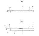
図1〜5は、本発明の実施の形態の1例を示している。まず、図1を参照しつつ、本例の脊椎用手術器具7について説明する。本例の脊椎用手術器具7は、骨粗鬆症などに起因して圧迫骨折した椎体内部に、骨セメントなどの骨充填材を充填するために利用するもので、中空管状のチューブ部8と、袋状のバルーン部9とを備える。このような構成を有する脊椎用手術器具7は、塩化ビニール、ポリエチレン、ポリプロピレンなどの高分子材料もしくはポリ乳酸、キトサン、グリコール酸と乳酸ポリエステルの化合物などの生体吸収性材料を溶融押出成形するなどして造られる。また、前記脊椎用手術器具7を脊椎内に挿入した状態で、その形状、位置および向きなどをX線装置により確認できるように、材料中にX線造影剤などからなる線(糸、テープなど)を混入しておくこともできる。また、前記脊椎用手術器具7を構成するチューブ部8とバルーン部9とは、同じ材質とすることもできるし、異なる材質にすることもできる。異なる材質にする場合には、たとえば、バルーン部9をチューブ部8に比べて剛性が低い(弾性係数が小さい)材質のものとすることができる。さらに、前記脊椎用手術器具7は、骨充填材の漏出防止の面から、表面に空孔が存在しないものや、使用する骨充填材を透過させない程度の大きさの空孔を有するものを好ましく使用できるが、骨充填材が著しく漏出しない程度の空孔を有するもの(メッシュ状のもの)であれば使用することは可能である。また、前記脊椎用手術器具7は、単一材料からなる単層構造に限定されず、複数材料からなる複層構造とすることもできる。 1 to 5 show an example of an embodiment of the present invention. First, the spinal surgical instrument 7 of this example will be described with reference to FIG. The spinal surgical instrument 7 of this example is used to fill a bone filling material such as bone cement into a vertebral body that has been fractured due to osteoporosis, and has a hollow
また、前記脊椎用手術器具7を構成するチューブ部8は、中空管状で、可撓性を有するとともに長さ方向両端部に開口部を有する。このチューブ部8は、患者の体型や骨折した椎体の大きさ、使用する骨充填材の種類などに応じて適宜好ましいサイズのものを使用することができる。たとえば、前記チューブ8の仕様は、内径寸法が3〜6mm、全長が500〜1000mm、肉厚が3〜500μmである。また、前記チューブ部8は、図示のような円筒状のものに限定されず、角筒状のものを使用することもできるし、これらを組み合わせたものを使用することもできる。また、前記チューブ部8の直径や肉厚は全長にわたり一定である必要はなく、適宜変更しても良い。 Moreover, the
一方、前記バルーン部9は、袋状で、前記チューブ部8の長さ方向中央部の円周方向の一部に、このチューブ部8と一体に設けられている。また、前記バルーン部9は、このチューブ部8を通じてその内部空間(収容空間)に空気圧あるいは骨充填材を供給される以前の状態で、図1の(A)に示したように、前記チューブ部8の外周面よりも径方向外側に突出しないように収納されている。図示の例では、前記バルーン部9を、前記チューブ部8の内部に折り畳んだ状態で収納している。ただし、バルーン部9の収納態様は、図示のような構造に限定されず、バルーン部9の形状、大きさ、材質、膨らみ易さなどを考慮して適宜好ましい態様を採用できる。たとえば、バルーン部9を弾性材料から造る場合には、このバルーン部9を萎ませた(収縮させた)状態で、前記チューブ部8の内部にそのまま(あるいは折り畳んで)収納することができる。 On the other hand, the
また、前記バルーン部9は、前記チューブ部8を通じてその内部空間に空気圧あるいは骨充填材が供給された場合に、図1の(B)に示したように、前記チューブ部8の外周面よりも径方向外側に膨出する(展開する)ように構成されている。図示の例では、前記バルーン部9の膨出時の形状を略球状としている。このバルーン部9の膨出時の大きさは、骨折した椎体の大きさ、椎体の潰れの程度、使用する骨充填材の種類などに応じて適宜好ましいサイズのものを選択できる。たとえば、前記バルーン部9の直径は10〜50mmとすることができる。また、バルーン部9の形状は、球状に限らず、半球状、柱状、ドーナツ状、円すい状、星状など、骨折の状態に応じて種々の形状を採用できる。なお、バルーン部9の形状が複雑化する際には、このバルーン部9の内部空間を細分化することもできる。また、バルーン部9の数は、1個に限定されず、骨折の状態に応じて、複数個(2個以上)設けることもできる。 In addition, when the air pressure or the bone filler is supplied to the internal space through the
以下、上述の様な構成を有する脊椎用手術器具7を使用して、骨折した椎体の内部に骨充填材を充填する手順について、図1に加えて図2〜図5を参照しつつ、説明する。
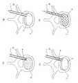
まず、脊椎外科の分野の手術で一般的に使用されるペディクルスクリューの刺入と同様の方法で、左右の椎弓根2a、2bから椎体3に向けて、経皮的にそれぞれ穴10a、10bを穿つ。そして、ロンジュールなどの図示しない破砕具を用いて、椎体3の内部の海綿状骨(骨梁)11を粉砕し、図2の(A)に示すように、前記両穴10a、10bの先端部(奥端部)同士を連通させる。特に、図示の例の場合には、椎体3が前後に分離するように骨折しているため、骨折線(イ)よりも前方側(図2の下側)で前記両穴10a、10bを連通させる。また、粉砕した海綿状骨11は、吸引などの手段により除去しておく。Hereinafter, with reference to FIGS. 2 to 5 in addition to FIG. 1, the procedure for filling the fractured vertebral body with the bone filler using the spinal surgical instrument 7 having the above-described configuration will be described. explain.
First, the
次いで、図示しない内視鏡を使用して、柔軟性のあるガイドワイヤ12を、片側の椎弓根2aに形成した一方の穴10aを通じて、椎体3の内部に挿入していく。一方、他側の椎弓根2bに形成した他方の穴10bからは図示しない鉗子を挿入する。そして、該鉗子により前記ガイドワイヤ12の先端部を把持したならば、このガイドワイヤ12を他方の穴10bから外側(背面側)に引き出す。これにより、図2の(B)に示すように、ガイドワイヤ12が、椎体3の内側を通過して左右の椎弓根2a、2bからそれぞれ引き出された状態となる。 Next, using an endoscope (not shown), a
その後、前記ガイドワイヤ12を案内として、前記脊椎用手術器具7を椎体3の内側に挿入していく。本例の場合には、このような挿入作業を、図4の(A)に示したような、インサータ13を利用して行う。このインサータ13は、前記脊椎用手術器具7を椎体3の内部に挿入する作業を容易にするための器具であり、たとえば、ポリエチレンやポリプロピレンなどの高分子材料製で可撓性を有し、その全長は前記脊椎用手術器具7(チューブ部8)とほぼ同様に500〜1000mmである。また、前記インサータ13は、その内側に前記ガイドワイヤ12を挿通可能な(ガイドワイヤ12の外径寸法よりも大きな内径寸法を有する)挿通孔14を有するとともに、部分円すい筒状の挿入部15と、円筒状の取付部16とを備える。このうちの挿入部15は、左右の椎弓根2a、2bに形成した各穴10a、10b内をスムーズに移動できるように、先端側の外径寸法を基端側の外径寸法よりも小さくしている。また、最も外径寸法が大きくなった部分(基端側部分)の外径寸法を、前記脊椎用手術器具7を構成するチューブ部8の長さ方向端部の外径寸法とほぼ同じとしている。一方、前記取付部16は、その外径寸法を前記チューブ部8の内径寸法よりも僅かに小さくしている。このため、図4の(B)に示したように、前記脊椎用手術器具7を、前記チューブインサータ13の取付部16に取り付ける(外嵌する)作業および取り外す(引き抜く)作業は、容易に行える。 Thereafter, the surgical instrument 7 for spine is inserted into the
前記脊椎用手術器具7を前記インサータ13に装着したのちは、前記ガイドワイヤ12の長さ方向一端部(椎弓根2a、2bを通じて皮膚の外側に引き出された部分)を、このインサータ13の挿通孔14内に前記挿入部15側から挿入する。そして、これらインサータ13と脊椎用手術器具7とを、前記ガイドワイヤ12を案内として、前記一方の穴10aから椎体3の内側へと挿入し、他方の穴10bを通じて椎体3の外側へと引き出す。これにより、図2の(C)に示したように、前記チューブ部8の長さ方向中央部およびバルーン部9が骨折線よりも前方に位置するとともに、このチューブ部8の長さ方向両端部が、左右の椎弓根2a、2bに形成された前記各穴10a、10bを通じて皮膚の外側(背面側)に引き出された状態となる。また、この状態で、X線装置などで透視しつつ、前記脊椎用手術器具7を回転させるなどして、前記バルーン部9の膨出方向(展開方向)が適正になるように調整する。なお、前記バルーン部9の膨出方向は、骨折の状態に応じて適宜決定される(図示の例では膨出方向を後向きとしている)。上述のようにして、前記脊椎用手術器具7を挿入したのちは、前記インサータ13とともに前記ガイドワイヤ12を引き抜き、椎体3(椎骨)の内部に、脊椎用手術器具7のみを留置する。 After the surgical instrument 7 for spine is attached to the
その後、前記チューブ部8の長さ方向一端側の開口部から、図5に示したような、略円柱状のストッパ17を挿入する。このストッパ17は、高分子ポリエチレン製あるいは気孔率の少ないハイドロキシアパタイト製で、その略中央部に軸方向に貫通する状態で排出孔18を有する。この排出孔18の内径寸法は、空気は容易に通過できるが骨充填材はほぼ通過できない程度の大きさであり、使用する骨充填材の種類との関係で適宜決定される。たとえば、このような排出孔18の内径寸法は1〜2mm程度である。また、前記ストッパ17は、前記チューブ部8の内側に実質的に隙間なく内嵌可能な外径寸法を有する。たとえば、このようなストッパ17の外径寸法は、前記チューブ8の内径寸法と同じかこれよりも僅かに小さい3〜6mmである。図示の例では、ストッパ17を先細のテーパ状とすることで、前記椎弓根(2a、2b)の骨内での固定性の向上を図っている。 Thereafter, a substantially
以上のような構成を有するストッパ17を、皮膚の外側に引き出された前記チューブ部8の長さ方向一端側の開口部から挿入し、このストッパ17を一方の椎弓根(2b)の内側に位置するまで移動させる。これにより、前記チューブ部8の長さ方向一端側の開口を前記椎弓根(2b)内で塞いだならば、注射器のような空気注入装置19を用いて、このチューブ部8の長さ方向他端側の開口部から空気を送り込む。これにより、図2の(D)および図3の(A)に示したように、前記バルーン部9の内部空間に空気圧を供給して、このバルーン部9を少しだけ膨出させる(展開させる)。本例の場合には、このようにバルーン部9を少しだけ膨出させることによって、このバルーン部9の内部空間に骨充填材6がスムーズに充填しやすくしている。なお、このようにバルーン部9が膨出したことは、X線装置などを用いて確認する。 The
次いで、前記チューブ部8の長さ方向他端部にセメント注入装置20を取り付け、このチューブ部8の内部空間に骨セメント(PMMA)などの骨充填材6を注入していく。特に本例の場合には、この注入作業を、前記チューブ部8のうち、皮膚の外側に引き出された長さ方向両端部を後方に引き寄せながら行う。このようにして骨充填材6を注入し始めると、前記チューブ部8の内側に挿入された前記ストッパ17の排出孔18から、前記脊椎用手術器具7内の空気が排出される(押し出される)とともに、図2の(E)および図3の(B)に示したように、前記バルーン部9の内部空間に骨充填材6が充填し始め、このバルーン部9が球状に膨らみ始める。そして、X線透視下のもと、椎体3の内部に十分量の骨充填材6が充填され、この椎体3の整復が確認されたならば、骨充填材6の注入を中止する。そして、前記チューブ部8の長さ方向他端部から前記セメント注入装置20を取り外し、このチューブ部8の長さ方向他端側の開口部から第二のストッパ21を挿入する。そして、図2の(F)に示したように、この第二のストッパ21を他方の椎弓根(2a)の内側に位置するまで移動させて、前記チューブ部8の長さ方向他端側の開口をこの椎弓根(2a)内で塞ぐ。これにより、前記脊椎用手術器具7からの骨充填材6の漏出を防止する。その後、前記チューブ部8の長さ方向一端および他端側からハサミと同等の機能を有する細い器具をそれぞれ挿入し、このチューブ部8の長さ方向両側部分を左右の椎弓根2a、2bの外側でそれぞれ切断し取り除いたのち、閉創することによって手術を終了する。 Next, a
以上のような本例の脊椎用手術器具7の場合には、骨充填材6を収容するためのバルーン部9と、このバルーン部9に骨充填材6を供給するチューブ部8とを一体に設けているため、前記特許文献3に記載されるような、椎体内で互いに分離される別体のバルーンと注入管とを利用して骨充填材を充填する場合に比べて、骨充填材6が椎体3の外部に漏出することをより有効に防止できる。 In the case of the spinal surgical instrument 7 of this example as described above, the
また、本例の脊椎用手術器具7を用いれば、チューブ部8の長さ方向中央部を椎体3を前後に分離する骨折線よりも前方に配置した状態で、このチューブ部8の長さ方向両端部を前記両椎弓根2a、2bを通じてそれぞれ皮膚の外側に(背面側に)引き出すことができる。このため、前記チューブ部8の長さ方向両端部を後方に引っ張りながら、骨充填材6を注入する作業が可能になる。言い換えれば、前後に分離した椎体3のうち、前方の椎体片を後方の椎体片に向けて押し付けながら、骨充填材6を注入することができる。この結果、骨折線が広がることを有効に防止しつつ、前記バルーン部9を膨出させて椎体3を整復し、該椎体3を補強および固定することができる。
以上のように、本例の脊椎用手術器具によれば、骨充填材6が椎体3の外部に漏出することを有効に防止できるとともに、椎体3を前後に分離するような骨折の治療にも有効に利用できる。In addition, when the spinal surgical instrument 7 of this example is used, the length of the
As described above, according to the spinal surgical instrument of this example, it is possible to effectively prevent the
なお、本例に使用する骨充填材の種類は特に問わないが、本例の脊椎用手術器具を使用すれば、脊柱管および静脈への骨充填材の漏出を有効に防止できるため、圧縮強度が高く、最大硬化までの所要時間が10分程度と短い、PMMAなどの骨セメントを好ましく使用できる。また、本例の脊椎用手術器具7を使用すれば、骨充填材が体液に触れることも有効に防止できるため、骨セメント以外にも、リン酸カルシウムペーストも好ましく使用できる。ただし、ハイドロキシアパタイトブロックなどの固形状の骨充填材に関しても、使用することは可能である。 The type of bone filler used in this example is not particularly limited. However, if the spinal surgical instrument of this example is used, leakage of the bone filler into the spinal canal and veins can be effectively prevented. A bone cement such as PMMA, which is high and requires a short time to maximum hardening of about 10 minutes, can be preferably used. In addition, when the spinal surgical instrument 7 of this example is used, it is possible to effectively prevent the bone filler from coming into contact with the body fluid. Therefore, besides the bone cement, a calcium phosphate paste can be preferably used. However, solid bone fillers such as hydroxyapatite blocks can also be used.
1 導入管
2a、2b 椎弓根
3 椎体
4 拡張用バルーン
5 空洞
6 骨充填材
7 脊椎用手術器具
8 チューブ部
9 バルーン部
10a、10b 穴
11 海綿状骨
12 ガイドワイヤ
13 チューブインサータ
14 挿通孔
15 挿入部
16 取付部
17 ストッパ
18 排出孔
19 空気注入装置
20 セメント注入装置
21 第二のストッパDESCRIPTION OF
Claims (3)
Translated fromJapanese可撓性を有するとともに長さ方向両端部に開口部を有する中空管状のチューブ部と、このチューブ部と一体に設けられたバルーン部とを備え、
このバルーン部が、前記チューブ部の長さ方向中間部に設けられており、このチューブ部を通じてその内部空間に空気圧あるいは前記骨充填材を供給される以前の状態で、このチューブ部の外面よりも外側に突出しないように収納されており、このチューブ部を通じてその内部空間に空気圧あるいは前記骨充填材が供給されることにより、このチューブ部の外面よりも外側に膨出することを特徴とする脊椎用手術器具。A spinal surgical instrument used to fill a vertebral body with a bone filler,
A hollow tubular tube portion having flexibility and having openings at both ends in the length direction, and a balloon portion provided integrally with the tube portion,
This balloon part is provided in the middle part in the longitudinal direction of the tube part, and in a state before air pressure or the bone filler is supplied to the internal space through the tube part, it is more than the outer surface of the tube part. The spine is stored so as not to protrude outwards, and is swelled outward from the outer surface of the tube part by supplying air pressure or the bone filler to the internal space through the tube part. Surgical instruments.
Priority Applications (1)
| Application Number | Priority Date | Filing Date | Title |
|---|---|---|---|
| JP2010234813AJP2012085804A (en) | 2010-10-19 | 2010-10-19 | Instrument for spine surgery |
Applications Claiming Priority (1)
| Application Number | Priority Date | Filing Date | Title |
|---|---|---|---|
| JP2010234813AJP2012085804A (en) | 2010-10-19 | 2010-10-19 | Instrument for spine surgery |
Publications (1)
| Publication Number | Publication Date |
|---|---|
| JP2012085804Atrue JP2012085804A (en) | 2012-05-10 |
Family
ID=46258112
Family Applications (1)
| Application Number | Title | Priority Date | Filing Date |
|---|---|---|---|
| JP2010234813APendingJP2012085804A (en) | 2010-10-19 | 2010-10-19 | Instrument for spine surgery |
Country Status (1)
| Country | Link |
|---|---|
| JP (1) | JP2012085804A (en) |
Cited By (1)
| Publication number | Priority date | Publication date | Assignee | Title |
|---|---|---|---|---|
| WO2014142132A1 (en) | 2013-03-13 | 2014-09-18 | 独立行政法人物質・材料研究機構 | Adhesive bone filler and adhesive bone filler kit |
Citations (4)
| Publication number | Priority date | Publication date | Assignee | Title |
|---|---|---|---|---|
| JP2001517997A (en)* | 1997-06-09 | 2001-10-09 | カイフォン インコーポレイテッド | System for treating broken or diseased bone using an expandable body |
| US20040098017A1 (en)* | 2002-09-30 | 2004-05-20 | Advanced Polymers, Incorporated | Apparatus and methods for bone, tissue and duct dilatation |
| US20070010845A1 (en)* | 2005-07-08 | 2007-01-11 | Gorman Gong | Directionally controlled expandable device and methods for use |
| US20070055201A1 (en)* | 2005-07-11 | 2007-03-08 | Seto Christine L | Systems and methods for providing cavities in interior body regions |
- 2010
- 2010-10-19JPJP2010234813Apatent/JP2012085804A/enactivePending
Patent Citations (4)
| Publication number | Priority date | Publication date | Assignee | Title |
|---|---|---|---|---|
| JP2001517997A (en)* | 1997-06-09 | 2001-10-09 | カイフォン インコーポレイテッド | System for treating broken or diseased bone using an expandable body |
| US20040098017A1 (en)* | 2002-09-30 | 2004-05-20 | Advanced Polymers, Incorporated | Apparatus and methods for bone, tissue and duct dilatation |
| US20070010845A1 (en)* | 2005-07-08 | 2007-01-11 | Gorman Gong | Directionally controlled expandable device and methods for use |
| US20070055201A1 (en)* | 2005-07-11 | 2007-03-08 | Seto Christine L | Systems and methods for providing cavities in interior body regions |
Cited By (1)
| Publication number | Priority date | Publication date | Assignee | Title |
|---|---|---|---|---|
| WO2014142132A1 (en) | 2013-03-13 | 2014-09-18 | 独立行政法人物質・材料研究機構 | Adhesive bone filler and adhesive bone filler kit |
Similar Documents
| Publication | Publication Date | Title |
|---|---|---|
| US10595884B2 (en) | Methods and apparatus for treating vertebral fractures | |
| JP5366966B2 (en) | Porous containment device and related method for stabilizing vertebral compression fractures | |
| AU2015246133B2 (en) | Systems and methods for vertebral or other bone structure height restoration and stabilization | |
| JP5159320B2 (en) | 3D implantable bone support | |
| US7722624B2 (en) | Expandable structures for deployment in interior body regions | |
| US20090299373A1 (en) | Kyphoplasty banded balloon catheter | |
| EP2010267B1 (en) | Instrumentation kit for delivering viscous bone filler material | |
| JP2005501649A (en) | Bone treatment system and method | |
| JP2002516697A (en) | Deployable preformed structure for placement within the internal body region | |
| US20080243122A1 (en) | Apparatuses and methods for bone screw augmentation | |
| JP2006297147A (en) | Systems for treating fractured or diseased bone using expandable bodies | |
| KR20120028873A (en) | Minimally invasive spine augmentation and stabilization system and method | |
| JP2007044544A (en) | Device for treating fractured and/or diseased bone | |
| CN107320173B (en) | Vertebral body expansion shaping systems and methods | |
| US20110028981A1 (en) | Bone graft measuring apparatus and method of use | |
| JP2012085804A (en) | Instrument for spine surgery |
Legal Events
| Date | Code | Title | Description |
|---|---|---|---|
| A621 | Written request for application examination | Free format text:JAPANESE INTERMEDIATE CODE: A621 Effective date:20131007 | |
| A521 | Written amendment | Free format text:JAPANESE INTERMEDIATE CODE: A523 Effective date:20131028 | |
| A977 | Report on retrieval | Free format text:JAPANESE INTERMEDIATE CODE: A971007 Effective date:20140425 | |
| A131 | Notification of reasons for refusal | Free format text:JAPANESE INTERMEDIATE CODE: A131 Effective date:20140513 | |
| A521 | Written amendment | Free format text:JAPANESE INTERMEDIATE CODE: A523 Effective date:20140711 | |
| A131 | Notification of reasons for refusal | Free format text:JAPANESE INTERMEDIATE CODE: A131 Effective date:20141118 | |
| A02 | Decision of refusal | Free format text:JAPANESE INTERMEDIATE CODE: A02 Effective date:20150317 |