JP2012075899A - Blade deployment mechanism for surgical forceps - Google Patents
Blade deployment mechanism for surgical forcepsDownload PDFInfo
- Publication number
- JP2012075899A JP2012075899AJP2011216795AJP2011216795AJP2012075899AJP 2012075899 AJP2012075899 AJP 2012075899AJP 2011216795 AJP2011216795 AJP 2011216795AJP 2011216795 AJP2011216795 AJP 2011216795AJP 2012075899 AJP2012075899 AJP 2012075899A
- Authority
- JP
- Japan
- Prior art keywords
- blade
- jaw
- forceps
- trigger
- shaft
- Prior art date
- Legal status (The legal status is an assumption and is not a legal conclusion. Google has not performed a legal analysis and makes no representation as to the accuracy of the status listed.)
- Granted
Links
Images


Classifications
- A—HUMAN NECESSITIES
- A61—MEDICAL OR VETERINARY SCIENCE; HYGIENE
- A61B—DIAGNOSIS; SURGERY; IDENTIFICATION
- A61B18/00—Surgical instruments, devices or methods for transferring non-mechanical forms of energy to or from the body
- A61B18/04—Surgical instruments, devices or methods for transferring non-mechanical forms of energy to or from the body by heating
- A61B18/12—Surgical instruments, devices or methods for transferring non-mechanical forms of energy to or from the body by heating by passing a current through the tissue to be heated, e.g. high-frequency current
- A61B18/14—Probes or electrodes therefor
- A61B18/1442—Probes having pivoting end effectors, e.g. forceps
- A61B18/1445—Probes having pivoting end effectors, e.g. forceps at the distal end of a shaft, e.g. forceps or scissors at the end of a rigid rod
- A—HUMAN NECESSITIES
- A61—MEDICAL OR VETERINARY SCIENCE; HYGIENE
- A61B—DIAGNOSIS; SURGERY; IDENTIFICATION
- A61B17/00—Surgical instruments, devices or methods
- A61B17/28—Surgical forceps
- A61B17/2812—Surgical forceps with a single pivotal connection
- A61B17/2833—Locking means
- A—HUMAN NECESSITIES
- A61—MEDICAL OR VETERINARY SCIENCE; HYGIENE
- A61B—DIAGNOSIS; SURGERY; IDENTIFICATION
- A61B17/00—Surgical instruments, devices or methods
- A61B17/28—Surgical forceps
- A61B17/2812—Surgical forceps with a single pivotal connection
- A—HUMAN NECESSITIES
- A61—MEDICAL OR VETERINARY SCIENCE; HYGIENE
- A61B—DIAGNOSIS; SURGERY; IDENTIFICATION
- A61B17/00—Surgical instruments, devices or methods
- A61B17/28—Surgical forceps
- A61B17/2812—Surgical forceps with a single pivotal connection
- A61B17/282—Jaws
- A—HUMAN NECESSITIES
- A61—MEDICAL OR VETERINARY SCIENCE; HYGIENE
- A61B—DIAGNOSIS; SURGERY; IDENTIFICATION
- A61B17/00—Surgical instruments, devices or methods
- A61B17/28—Surgical forceps
- A61B17/285—Surgical forceps combined with cutting implements
- A—HUMAN NECESSITIES
- A61—MEDICAL OR VETERINARY SCIENCE; HYGIENE
- A61B—DIAGNOSIS; SURGERY; IDENTIFICATION
- A61B17/00—Surgical instruments, devices or methods
- A61B17/28—Surgical forceps
- A61B17/29—Forceps for use in minimally invasive surgery
- A—HUMAN NECESSITIES
- A61—MEDICAL OR VETERINARY SCIENCE; HYGIENE
- A61B—DIAGNOSIS; SURGERY; IDENTIFICATION
- A61B17/00—Surgical instruments, devices or methods
- A61B17/32—Surgical cutting instruments
- A61B2017/320052—Guides for cutting instruments
- A—HUMAN NECESSITIES
- A61—MEDICAL OR VETERINARY SCIENCE; HYGIENE
- A61B—DIAGNOSIS; SURGERY; IDENTIFICATION
- A61B18/00—Surgical instruments, devices or methods for transferring non-mechanical forms of energy to or from the body
- A61B2018/00571—Surgical instruments, devices or methods for transferring non-mechanical forms of energy to or from the body for achieving a particular surgical effect
- A61B2018/0063—Sealing
- A—HUMAN NECESSITIES
- A61—MEDICAL OR VETERINARY SCIENCE; HYGIENE
- A61B—DIAGNOSIS; SURGERY; IDENTIFICATION
- A61B18/00—Surgical instruments, devices or methods for transferring non-mechanical forms of energy to or from the body
- A61B18/04—Surgical instruments, devices or methods for transferring non-mechanical forms of energy to or from the body by heating
- A61B18/12—Surgical instruments, devices or methods for transferring non-mechanical forms of energy to or from the body by heating by passing a current through the tissue to be heated, e.g. high-frequency current
- A61B18/14—Probes or electrodes therefor
- A61B2018/1405—Electrodes having a specific shape
- A61B2018/1412—Blade
- A—HUMAN NECESSITIES
- A61—MEDICAL OR VETERINARY SCIENCE; HYGIENE
- A61B—DIAGNOSIS; SURGERY; IDENTIFICATION
- A61B18/00—Surgical instruments, devices or methods for transferring non-mechanical forms of energy to or from the body
- A61B18/04—Surgical instruments, devices or methods for transferring non-mechanical forms of energy to or from the body by heating
- A61B18/12—Surgical instruments, devices or methods for transferring non-mechanical forms of energy to or from the body by heating by passing a current through the tissue to be heated, e.g. high-frequency current
- A61B18/14—Probes or electrodes therefor
- A61B18/1442—Probes having pivoting end effectors, e.g. forceps
- A61B2018/1452—Probes having pivoting end effectors, e.g. forceps including means for cutting
- A61B2018/1455—Probes having pivoting end effectors, e.g. forceps including means for cutting having a moving blade for cutting tissue grasped by the jaws
- A—HUMAN NECESSITIES
- A61—MEDICAL OR VETERINARY SCIENCE; HYGIENE
- A61B—DIAGNOSIS; SURGERY; IDENTIFICATION
- A61B90/00—Instruments, implements or accessories specially adapted for surgery or diagnosis and not covered by any of the groups A61B1/00 - A61B50/00, e.g. for luxation treatment or for protecting wound edges
- A61B90/08—Accessories or related features not otherwise provided for
- A61B2090/0801—Prevention of accidental cutting or pricking
- A61B2090/08021—Prevention of accidental cutting or pricking of the patient or his organs
Landscapes
- Health & Medical Sciences (AREA)
- Surgery (AREA)
- Life Sciences & Earth Sciences (AREA)
- Engineering & Computer Science (AREA)
- Veterinary Medicine (AREA)
- Molecular Biology (AREA)
- Nuclear Medicine, Radiotherapy & Molecular Imaging (AREA)
- Public Health (AREA)
- Biomedical Technology (AREA)
- Heart & Thoracic Surgery (AREA)
- Medical Informatics (AREA)
- General Health & Medical Sciences (AREA)
- Animal Behavior & Ethology (AREA)
- Ophthalmology & Optometry (AREA)
- Otolaryngology (AREA)
- Plasma & Fusion (AREA)
- Physics & Mathematics (AREA)
- Surgical Instruments (AREA)
- Chemical & Material Sciences (AREA)
- Analytical Chemistry (AREA)
Abstract
Translated fromJapaneseDescription
Translated fromJapanese (背景)
本開示は、外科鉗子に関し、より具体的には、組織を密閉し、かつ分離するための外科鉗子に用いられるブレード展開メカニズムに関する。(background)
The present disclosure relates to surgical forceps, and more particularly to a blade deployment mechanism used in surgical forceps for sealing and separating tissue.
(技術分野)
鉗子は、血管または組織を掴み、クランプし、そして締め付けるために、鉗子のジョーの間の機械的動作に頼るプライヤーのような器具である。電気外科鉗子は、機械的クランピング動作と、組織を凝固し、そして/または焼灼するために、組織および血管を加熱することによって止血に影響するための電気エネルギーとの両方を利用する。ある外科手順は、より簡単に組織を焼灼することを要求し、組織、血管およびある血管束を「密閉する」ために、クランピング圧力、正確な電気外科エネルギーの制御およびギャップの距離(すなわち、組織の周りに閉じられた場合に、向かい合うジョー部材の間の距離)の特有の組み合わせに頼る。(Technical field)
A forceps is a pliers-like instrument that relies on mechanical movement between the jaws of a forceps to grasp, clamp and tighten a blood vessel or tissue. Electrosurgical forceps utilize both a mechanical clamping action and electrical energy to affect hemostasis by heating the tissue and blood vessels to coagulate and / or cauterize the tissue. Some surgical procedures require easier cauterization of the tissue and clamping pressure, precise electrosurgical energy control and gap distance (ie, to “seal” the tissue, blood vessels and certain vessel bundles (ie, Relies on a unique combination of distances between opposing jaw members) when closed around tissue.
典型的には、一旦血管が密閉されると、外科医は、新しく形成された組織密閉に沿って血管を正確に切断しなければならない。従って、多くの血管密閉器具は、組織の密閉を形成する後に組織を効率的に切断するナイフまたはブレード部材を組み込むように、設計されておる。 Typically, once a vessel is sealed, the surgeon must accurately cut the vessel along the newly formed tissue seal. Accordingly, many vascular sealing devices are designed to incorporate a knife or blade member that efficiently cuts tissue after forming the tissue seal.
(要約)
本発明の1つの実施形態に従って、鉗子が提供される。鉗子は、第1のシャフト部材および第2のシャフト部材を含む。シャフト部材の各々は、シャフト部材の遠位端に配置されているジョー部材を有する。ジョー部材のうちの一方(または両方)は、ジョー部材の間の組織を掴むために、開放位置から閉鎖位置までもう一方に対して移動可能である。ジョー部材のうちの1つ(または両方)は、ジョー部材を通すブレードの往復運動のために構成される。トリガアセンブリは、引き込まれた位置と拡張された位置との間にブレードを選択的に移動させるために構成される。拡張された位置において、ブレードは、部分的に、または全部にジョー部材を通して延びる。トリガアセンブリは、回転可能なトリガ、1つ以上のリンク機構、および妨害部材を含む。リンク機構は、トリガの回転が、引き込まれた位置と、拡張された位置との間にブレードの移動をもたらすように、第1の端部で回転可能なトリガに連結されており、かつ第2の端部でブレードに連結されている。妨害部材は、ロックされた位置とロックされていない位置との間に移動可能である。ジョー部材が開放位置にある場合に、妨害部材は、ロックされた位置にあり、引き込まれた位置から拡張された位置までブレードの移動をさせないために、リンク機構を係合する。ジョー部材が閉鎖位置にある場合に、妨害部材は、ロックされていない位置に動かされ、ブレードの移動を可能にする。(wrap up)
In accordance with one embodiment of the present invention, a forceps is provided. The forceps includes a first shaft member and a second shaft member. Each of the shaft members has a jaw member disposed at the distal end of the shaft member. One (or both) of the jaw members is movable relative to the other from an open position to a closed position to grasp tissue between the jaw members. One (or both) of the jaw members is configured for reciprocation of the blade through the jaw members. The trigger assembly is configured to selectively move the blade between a retracted position and an expanded position. In the expanded position, the blade extends partially or fully through the jaw members. The trigger assembly includes a rotatable trigger, one or more linkages, and an obstruction member. The linkage is coupled to a trigger that is rotatable at a first end so that rotation of the trigger results in movement of the blade between a retracted position and an expanded position, and a second Is connected to the blade at the end. The obstructing member is movable between a locked position and an unlocked position. When the jaw member is in the open position, the obstruction member is in the locked position and engages the linkage to prevent movement of the blade from the retracted position to the expanded position. When the jaw member is in the closed position, the obstructing member is moved to the unlocked position to allow movement of the blade.
一実施形態において、付勢部材は、ブレードを引き込まれた位置に向かって付勢するために提供される。妨害部材も、ロックされた位置に向かって付勢され得る。 In one embodiment, a biasing member is provided to bias the blade toward the retracted position. The obstructing member can also be biased towards the locked position.
もう1つの実施形態において、妨害部材は、ロックされた位置とロックされていない位置との間のピボットの周りに回転可能である。前述のように、ロックされた位置において、妨害部材は、ブレードの移動をさせないためにリンク機構を係合し、その一方で、ロックされていない位置において、妨害部材は、リンク機構から係合解除され、従って、ブレードの移動が可能にされる。 In another embodiment, the obstruction member is rotatable about a pivot between a locked position and an unlocked position. As described above, in the locked position, the blocking member engages the linkage to prevent movement of the blade, while in the unlocked position, the blocking member disengages from the linkage. Therefore, movement of the blade is made possible.
なおもう1つの実施形態において、第2のシャフト部材から延びるタブは、ロックされた位置からロックされていない位置まで妨害部材を回転させるために、妨害部材と接触し、それによって、閉鎖位置へのジョー部材の動きで、リンク機構から妨害部材を係合解除する。代替的に、第2のシャフト部材は、ロックされた位置からロックされていない位置まで妨害部材を回転させるために、閉鎖位置へのジョー部材の動きで、妨害部材から延びるタブと接触し得、それによって、リンク機構から妨害部材を係合解除する。 In yet another embodiment, a tab extending from the second shaft member contacts the obstruction member to rotate the obstruction member from the locked position to the unlocked position, thereby moving to the closed position. The movement of the jaw member disengages the blocking member from the link mechanism. Alternatively, the second shaft member may contact a tab extending from the obstruction member with movement of the jaw member to a closed position to rotate the obstruction member from a locked position to an unlocked position; Thereby, the interference member is disengaged from the link mechanism.
なおもう1つの実施形態において、ジョー部材のうちの1つ(または両方)は、電気外科エネルギーの供給源に接続するように適合される。従って、アクチュエータは、ジョー部材への電気外科エネルギーの供給を制御するために提供され得る。特に、第1のシャフト部材は、アクチュエータを含み得、第2のシャフト部材は、ジョー部材への所定の閉鎖力の適用で、第2のシャフト部材が、ジョー部材に電気外科エネルギーを供給するために、アクチュエータを作動させるように構成され得る。 In yet another embodiment, one (or both) of the jaw members are adapted to connect to a source of electrosurgical energy. Thus, an actuator can be provided to control the supply of electrosurgical energy to the jaw members. In particular, the first shaft member may include an actuator, and the second shaft member provides electrosurgical energy to the jaw member upon application of a predetermined closure force to the jaw member. And may be configured to actuate the actuator.
本発明のもう1つの実施形態に従って、鉗子が提供される。前の実施形態のように、鉗子は、第1のシャフト部材および第2のシャフト部材を含み、シャフト部材の各々は、シャフト部材の遠位端に配置されているジョー部材を有する。ジョー部材のうちの1つ(または両方)は、ジョー部材の間の組織を掴むために、開放位置から閉鎖位置まで移動可能である。ジョー部材のうちの1つ(または両方)は、ジョー部材を通すブレードの往復運動のために構成される。トリガアセンブリは、引き込まれた位置と拡張された位置との間にブレードを選択的に移動させるために構成される。トリガアセンブリは、トリガ、アーム、カンチレバー、および1つ以上のリンク機構を含む。アームは、トリガに連結される第1の端部と、自由な第2の端部とを有する。カンチレバーは、カンチレバーにおいて係合凹所を規定し、第1の位置と第2の位置との間のピボットの周りに回転可能である。リンク機構は、第1の端部でカンチレバーに連結されており、かつ第2の端部でブレードに連結されている。タブは、第2のシャフト部材から延びる。トリガの近位移動は、引き込まれた位置から拡張された位置まで遠位にブレードを移動させるために、第1の位置から第2の位置までカンチレバーを回転させるように、タブは、閉鎖位置へのジョー部材の動きで、カンチレバーの係合凹所内にアームの自由な端部を押し込むように構成される。 In accordance with another embodiment of the present invention, a forceps is provided. As in the previous embodiment, the forceps includes a first shaft member and a second shaft member, each of the shaft members having a jaw member disposed at the distal end of the shaft member. One (or both) of the jaw members is movable from an open position to a closed position to grasp tissue between the jaw members. One (or both) of the jaw members is configured for reciprocation of the blade through the jaw members. The trigger assembly is configured to selectively move the blade between a retracted position and an expanded position. The trigger assembly includes a trigger, an arm, a cantilever, and one or more linkages. The arm has a first end coupled to the trigger and a free second end. The cantilever defines an engagement recess in the cantilever and is rotatable about a pivot between the first position and the second position. The link mechanism is connected to the cantilever at the first end and is connected to the blade at the second end. A tab extends from the second shaft member. The proximal movement of the trigger rotates the cantilever from the first position to the second position to move the blade distally from the retracted position to the expanded position, so that the tab moves to the closed position. The movement of the jaw member is configured to push the free end of the arm into the engagement recess of the cantilever.
一実施形態において、付勢部材は、ブレードを引き込まれた位置に向かって付勢するために提供される。付勢部材はまた、トリガを最初の位置に向かって付勢するために提供され得る。さらに、アームは、板ばねであり得、オプション的に、カンチレバーの係合凹所から離れて付勢され得る。 In one embodiment, a biasing member is provided to bias the blade toward the retracted position. A biasing member may also be provided to bias the trigger toward the initial position. Further, the arm can be a leaf spring and can optionally be biased away from the engagement recess of the cantilever.
もう1つの実施形態において、第1のシャフトは、第1のシャフトにおいて規定されるカンチレバーの溝を含む。カンチレバーの溝は、第1の位置と第2の位置との間にカンチレバーの回転を可能にするように構成される。 In another embodiment, the first shaft includes a cantilever groove defined in the first shaft. The cantilever groove is configured to allow rotation of the cantilever between the first position and the second position.
なおもう1つの実施形態において、ジョー部材のうちの1つ(または両方)は、電気外科エネルギーの供給源に接触するように適合される。 In yet another embodiment, one (or both) of the jaw members are adapted to contact a source of electrosurgical energy.
なおもう1つの実施形態において、カンチレバーの係合凹所は、カンチレバーが第2の位置へ回転される場合に、アームの自由な端部が係合凹所から係合解除されるように構成される。 In yet another embodiment, the engagement recess of the cantilever is configured such that the free end of the arm is disengaged from the engagement recess when the cantilever is rotated to the second position. The
なお本発明のもう1つの実施形態に従って、鉗子が提供される。鉗子は、第1のシャフト部材および第2のシャフト部材を含み、シャフト部材の各々は、ジョー部材を有する。ジョー部材のうちの1つ(または両方)は、ジョー部材の間の組織を掴むために、開放位置から閉鎖位置まで移動可能である。ジョー部材のうちの1つ(または両方)は、ジョー部材を通すブレードの往復運動のために構成される。引き込まれた位置と拡張された位置との間にブレードを選択的に移動させるために構成されるトリガアセンブリは、回転可能なトリガ、1つ以上のリンク機構、およびピストンを含む。リンク機構は、トリガの回転が、引き込まれた位置と拡張された位置との間のブレードの移動をもたらすように、第1の端部で回転可能なトリガに連結されており、かつ第2の端部でブレードに連結されている。ピストンは、第1の端部でリンク機構に連結されており、かつ第2の端部で第2のシャフト部材に連結されている。ピストンは、収縮された位置と拡張された位置との間に移動可能である。ピストンは、拡張された位置にある場合に、引き込まれた位置から拡張された位置までブレードの移動をさせない。 According to yet another embodiment of the present invention, a forceps is provided. The forceps includes a first shaft member and a second shaft member, and each of the shaft members has a jaw member. One (or both) of the jaw members is movable from an open position to a closed position to grasp tissue between the jaw members. One (or both) of the jaw members is configured for reciprocation of the blade through the jaw members. A trigger assembly configured to selectively move a blade between a retracted position and an expanded position includes a rotatable trigger, one or more linkages, and a piston. The linkage is coupled to a trigger that is rotatable at a first end such that rotation of the trigger results in movement of the blade between a retracted position and an expanded position, and a second It is connected to the blade at the end. The piston is connected to the link mechanism at the first end, and is connected to the second shaft member at the second end. The piston is movable between a retracted position and an expanded position. When the piston is in the expanded position, it does not move the blade from the retracted position to the expanded position.
第1の付勢部材は、ブレードを引き込まれた位置に向かって付勢するために提供され得、そして/または、第2の付勢部材は、ピストンを収縮された位置に向かって付勢するために、ピストン内に配置され得る。 A first biasing member may be provided to bias the blade toward the retracted position and / or a second biasing member biases the piston toward the retracted position. For this purpose, it can be arranged in the piston.
もう1つの実施形態において、ピストンは、1つ以上のリンク機構に旋回可能に連結されている。 In another embodiment, the piston is pivotally connected to one or more linkages.
なおもう1つの実施形態において、ジョー部材が開放位置にある場合に、ブレードが拡張された位置に移動することをさせないように、ピストンは、開放位置へのジョー部材の動きで、拡張された位置に動かされる。ジョー部材の開放位置は、ジョー部材が互いに対して少なくとも約5度で角度を付けられている位置に対応し得る。 In yet another embodiment, the piston is moved to the expanded position by movement of the jaw member to the open position so that the blade does not move to the extended position when the jaw member is in the open position. Moved to. The open position of the jaw members may correspond to positions where the jaw members are angled at least about 5 degrees relative to each other.
なおもう1つの実施形態において、ピストンは、ジョー部材が閉鎖位置から開放位置まで動かされる場合に、ブレードを引き込まれた位置に戻すようにさらに構成される。 In yet another embodiment, the piston is further configured to return the blade to the retracted position when the jaw member is moved from the closed position to the open position.
本発明は、例えば以下の項目を提供する。
(項目1)
鉗子であって、該鉗子は、
第1のシャフト部材および第2のシャフト部材であって、該第1のシャフト部材および第2のシャフト部材は、それぞれ、該シャフト部材の遠位端に配置されているジョー部材を有し、該ジョー部材のうちの少なくとも1つは、開放位置から、該ジョー部材の間の組織を掴むための閉鎖位置まで移動可能であり、該ジョー部材のうちの少なくとも1つは、該ジョー部材を通るブレードの往復運動のために構成される、第1のシャフト部材および第2のシャフト部材と、
引き込まれた位置と拡張された位置との間で該ブレードを選択的に移動するように構成されるトリガアセンブリであって、該ブレードは、該拡張された位置において、該少なくとも1つのジョー部材を少なくとも部分的に通って延びる、トリガアセンブリと
を備え、
該トリガアセンブリは、
回転可能なトリガと、
少なくとも1つのリンク機構であって、該少なくとも1つのリンク機構は、第1の端部で該回転可能なトリガに連結され、かつ第2の端部で該ブレードに連結されており、その結果、該トリガの回転が、該引き込まれた位置と該拡張された位置との間での該ブレードの移動をもたらす、少なくとも1つのリンク機構と、
妨害部材であって、該妨害部材は、該ジョー部材が該開放位置にある場合のロックされた位置と、該ジョー部材が該閉鎖位置にある場合のロックされていない位置との間で移動可能であり、該妨害部材は、該ロックされた位置にある場合に、該少なくとも1つのリンク機構を係合して、該引き込まれた位置から該拡張された位置まで該ブレードの移動を抑制するように構成される、妨害部材と
を含む、鉗子。
(項目2)
上記ブレードを上記引き込まれた位置に向けて付勢するための少なくとも1つの付勢部材をさらに備える、上記項目のいずれかに記載の鉗子。
(項目3)
上記妨害部材は、上記ロックされた位置に向けて付勢される、上記項目のいずれかに記載の鉗子。
(項目4)
上記妨害部材は、上記ロックされた位置と、上記ロックされていない位置との間で、ピボットの周りで回転可能であり、該ロックされた位置において、該妨害部材は、上記少なくとも1つのリンク機構を係合し、該ロックされていない位置において、該妨害部材は、該少なくとも1つのリンク機構から係合解除される、上記項目のいずれかに記載の鉗子。
(項目5)
上記第2のシャフト部材から延びるタブは、上記妨害部材に接触することにより、該妨害部材を上記ロックされた位置から上記ロックされていない位置まで回転させて、上記閉鎖位置への上記ジョー部材の移動の際に、上記少なくとも1つのリンク機構から該妨害部材を係合解除する、上記項目のいずれかに記載の鉗子。
(項目6)
上記第2のシャフト部材は、上記閉鎖位置への上記ジョー部材の移動の際に、上記妨害部材から延びるタブに接触することにより、該妨害部材を上記ロックされた位置から上記ロックされていない位置まで回転させて、上記少なくとも1つのリンク機構から上記妨害部材を係合解除する、上記項目のいずれかに記載の鉗子。
(項目7)
上記ジョー部材のうちの少なくとも1つは、電気外科エネルギーの供給源に接続するように適合され、上記鉗子は、該少なくとも1つのジョー部材への電気外科エネルギーの供給を制御するためのアクチュエータをさらに備える、上記項目のいずれかに記載の鉗子。
(項目8)
上記第1のシャフト部材は、アクチュエータを含み、上記ジョー部材への所定の閉鎖力の適用の際に、上記第2のシャフト部材は、該少なくとも1つのジョー部材に電気外科エネルギーを供給するために、該アクチュエータを作動させる、上記項目のいずれかに記載の鉗子。
(項目9)
鉗子であって、該鉗子は、
第1のシャフト部材および第2のシャフト部材であって、該第1のシャフト部材および第2のシャフト部材は、それぞれ、該シャフト部材の遠位端に配置されているジョー部材を有し、該ジョー部材のうちの少なくとも1つは、開放位置から、該ジョー部材の間の組織を掴むための閉鎖位置まで移動可能であり、該ジョー部材のうちの少なくとも1つは、該ジョー部材を通るブレードの往復運動のために構成される、第1のシャフト部材および第2のシャフト部材と、
引き込まれた位置と、拡張された位置との間で該ブレードを選択的に移動させるように構成されるトリガアセンブリであって、該ブレードは、該拡張された位置において、該少なくとも1つのジョー部材を少なくとも部分的に通って延びる、トリガアセンブリと
を備え、
該トリガアセンブリは、
トリガと、
アクチュエータに連結される第1の端部を有し、かつ自由な第2の端部を有するアームと、
カンチレバーであって、該カンチレバーは、該カンチレバー内に係合凹所を規定し、第1の位置と第2の位置との間でピボットの周りで回転可能である、カンチレバーと、
第1の端部で該カンチレバーに連結され、かつ第2の端部で該ブレードに連結されている少なくとも1つのリンク機構と、
該第2のシャフト部材から延びるタブであって、該タブは、該閉鎖位置への該ジョー部材の移動の際に、該カンチレバーの該係合凹所内に該アームの該自由な端部を押し込むように構成され、その結果、該トリガの近位移動は、該引き込まれた位置から該拡張された位置まで該ブレードを遠位に移動させるために、該第1の位置から該第2の位置まで該カンチレバーを回転させる、タブと
を含む、鉗子。
(項目10)
上記ブレードを上記引き込まれた位置に向けて付勢するための少なくとも1つの付勢部材をさらに備える、上記項目のいずれかに記載の鉗子。
(項目11)
上記トリガを最初の位置に向けて付勢するための少なくとも1つの付勢部材をさらに備える、上記項目のいずれかに記載の鉗子。
(項目12)
上記アームは、板ばねである、上記項目のいずれかに記載の鉗子。
(項目13)
上記第1のシャフトは、該第1のシャフト内に規定されるカンチレバーの溝を含み、該カンチレバーの溝は、該カンチレバーの溝内での該カンチレバーの回転を可能にするように構成される、上記項目のいずれかに記載の鉗子。
(項目14)
上記ジョー部材のうちの少なくとも1つは、電気外科エネルギーの供給源に接続するように適合される、上記項目のいずれかに記載の鉗子。
(項目15)
上記係合凹所は、上記カンチレバーが上記第2の位置へ回転される場合に、上記アームの上記自由な端部が該係合凹所から係合解除されるように構成される、上記項目のいずれかに記載の鉗子。
(項目16)
鉗子であって、該鉗子は、
第1のシャフト部材および第2のシャフト部材であって、該第1のシャフト部材および第2のシャフト部材は、それぞれ、該シャフト部材の遠位端に配置されているジョー部材を有し、該ジョー部材のうちの少なくとも1つは、開放位置から、該ジョー部材の間の組織を掴むための閉鎖位置まで移動可能であり、該ジョー部材のうちの少なくとも1つは、該ジョー部材を通るブレードの往復運動のために構成される、第1のシャフト部材および第2のシャフト部材と、
引き込まれた位置と拡張された位置との間で該ブレードを選択的に移動させるように構成されるトリガアセンブリであって、該ブレードは、該拡張された位置において、該少なくとも1つのジョー部材を少なくとも部分的に通って延びる、トリガアセンブリと
を備え、
該トリガアセンブリは、
回転可能なトリガと、
少なくとも1つのリンク機構であって、該少なくとも1つのリンク機構は、第1の端部で該回転可能なトリガに連結され、かつ第2の端部で該ブレードに連結されており、その結果、該トリガの回転が、該引き込まれた位置と該拡張された位置との間での該ブレードの移動をもたらす、少なくとも1つのリンク機構と、
ピストンであって、該ピストンは、第1の端部で該少なくとも1つのリンク機構に連結され、かつ第2の端部で該第2のシャフト部材に連結されているピストンであって、該ピストンは、収縮された位置と拡張された位置との間で移動可能であり、該ピストンは、該拡張された位置にある場合に、該引き込まれた位置から該拡張された位置までの該ブレードの移動を抑制するように構成される、ピストンと
を含む、鉗子。
(項目17)
上記ピストンを上記収縮された位置に向けて付勢する、該ピストン内に配置される付勢部材をさらに備える、上記項目のいずれかに記載の鉗子。
(項目18)
上記ピストンは、上記少なくとも1つのリンク機構に旋回可能に連結されている、上記項目のいずれかに記載の鉗子。
(項目19)
上記ジョー部材が上記開放位置に移動する場合に、上記ピストンが上記拡張された位置に移動し、その結果、上記ブレードが上記拡張された位置に移動することを抑制する、上記項目のいずれかに記載の鉗子。
(項目20)
上記ピストンは、上記ジョー部材が上記閉鎖位置から上記開放位置まで移動される場合に、上記ブレードを上記引き込まれた位置に戻すようにさらに構成される、上記項目のいずれかに記載の鉗子。For example, the present invention provides the following items.
(Item 1)
A forceps, the forceps being
A first shaft member and a second shaft member, each of the first shaft member and the second shaft member having a jaw member disposed at a distal end of the shaft member; At least one of the jaw members is movable from an open position to a closed position for grasping tissue between the jaw members, and at least one of the jaw members is a blade that passes through the jaw members. A first shaft member and a second shaft member configured for reciprocal movement of
A trigger assembly configured to selectively move the blade between a retracted position and an expanded position, the blade having the at least one jaw member in the expanded position. A trigger assembly extending at least partially through,
The trigger assembly includes:
A rotatable trigger,
At least one linkage, wherein the at least one linkage is coupled to the rotatable trigger at a first end and to the blade at a second end; At least one linkage wherein rotation of the trigger results in movement of the blade between the retracted position and the expanded position;
An obstruction member, the obstruction member being movable between a locked position when the jaw member is in the open position and an unlocked position when the jaw member is in the closed position. The blocking member engages the at least one linkage mechanism to restrain movement of the blade from the retracted position to the expanded position when in the locked position. A forceps comprising: an obstruction member.
(Item 2)
The forceps according to any of the preceding items, further comprising at least one biasing member for biasing the blade toward the retracted position.
(Item 3)
The forceps according to any one of the above items, wherein the blocking member is biased toward the locked position.
(Item 4)
The obstructing member is rotatable about a pivot between the locked position and the unlocked position, in which the obstructing member comprises the at least one linkage mechanism. The forceps according to any of the preceding items, wherein the blocking member is disengaged from the at least one linkage in the unlocked position.
(Item 5)
A tab extending from the second shaft member contacts the obstruction member to rotate the obstruction member from the locked position to the unlocked position, so that the jaw member is moved to the closed position. The forceps according to any one of the above items, wherein the obstruction member is disengaged from the at least one link mechanism during movement.
(Item 6)
The second shaft member contacts the tab extending from the obstruction member during movement of the jaw member to the closed position, thereby moving the obstruction member from the locked position to the unlocked position. The forceps according to any one of the above items, wherein the interference member is disengaged from the at least one link mechanism.
(Item 7)
At least one of the jaw members is adapted to connect to a source of electrosurgical energy, and the forceps further includes an actuator for controlling the supply of electrosurgical energy to the at least one jaw member. The forceps according to any one of the above items.
(Item 8)
The first shaft member includes an actuator, and the second shaft member provides electrosurgical energy to the at least one jaw member upon application of a predetermined closure force to the jaw member. The forceps according to any one of the above items, wherein the actuator is operated.
(Item 9)
A forceps, the forceps being
A first shaft member and a second shaft member, each of the first shaft member and the second shaft member having a jaw member disposed at a distal end of the shaft member; At least one of the jaw members is movable from an open position to a closed position for grasping tissue between the jaw members, and at least one of the jaw members is a blade that passes through the jaw members. A first shaft member and a second shaft member configured for reciprocal movement of
A trigger assembly configured to selectively move the blade between a retracted position and an expanded position, wherein the blade is in the expanded position the at least one jaw member A trigger assembly extending at least partially through
The trigger assembly includes:
Trigger,
An arm having a first end coupled to the actuator and having a free second end;
A cantilever, wherein the cantilever defines an engagement recess in the cantilever and is rotatable about a pivot between a first position and a second position;
At least one linkage coupled to the cantilever at a first end and coupled to the blade at a second end;
A tab extending from the second shaft member that pushes the free end of the arm into the engagement recess of the cantilever upon movement of the jaw member to the closed position Configured so that the proximal movement of the trigger causes the blade to move distally from the retracted position to the expanded position from the first position to the second position. Rotating the cantilever until it includes a tab and a forceps.
(Item 10)
The forceps according to any of the preceding items, further comprising at least one biasing member for biasing the blade toward the retracted position.
(Item 11)
The forceps according to any of the preceding items, further comprising at least one biasing member for biasing the trigger toward an initial position.
(Item 12)
The forceps according to any one of the above items, wherein the arm is a leaf spring.
(Item 13)
The first shaft includes a cantilever groove defined in the first shaft, the cantilever groove configured to allow rotation of the cantilever within the cantilever groove. The forceps according to any of the above items.
(Item 14)
The forceps according to any of the preceding items, wherein at least one of the jaw members is adapted to connect to a source of electrosurgical energy.
(Item 15)
The item, wherein the engagement recess is configured such that the free end of the arm is disengaged from the engagement recess when the cantilever is rotated to the second position. The forceps according to any one of the above.
(Item 16)
A forceps, the forceps being
A first shaft member and a second shaft member, each of the first shaft member and the second shaft member having a jaw member disposed at a distal end of the shaft member; At least one of the jaw members is movable from an open position to a closed position for grasping tissue between the jaw members, and at least one of the jaw members is a blade that passes through the jaw members. A first shaft member and a second shaft member configured for reciprocal movement of
A trigger assembly configured to selectively move the blade between a retracted position and an expanded position, the blade engaging the at least one jaw member in the expanded position; A trigger assembly extending at least partially through,
The trigger assembly includes:
A rotatable trigger,
At least one linkage, wherein the at least one linkage is coupled to the rotatable trigger at a first end and to the blade at a second end; At least one linkage wherein rotation of the trigger results in movement of the blade between the retracted position and the expanded position;
A piston coupled to the at least one linkage at a first end and coupled to the second shaft member at a second end, the piston Is movable between a retracted position and an expanded position, and when the piston is in the expanded position, the blade is moved from the retracted position to the expanded position. A forceps comprising a piston configured to inhibit movement.
(Item 17)
The forceps according to any one of the preceding items, further comprising a biasing member disposed in the piston that biases the piston toward the contracted position.
(Item 18)
The forceps according to any one of the above items, wherein the piston is pivotally connected to the at least one link mechanism.
(Item 19)
Any of the above items, wherein when the jaw member moves to the open position, the piston moves to the expanded position, and as a result, the blade is prevented from moving to the expanded position. The forceps described.
(Item 20)
The forceps according to any of the preceding items, wherein the piston is further configured to return the blade to the retracted position when the jaw member is moved from the closed position to the open position.
(摘要)
鉗子は、第1のシャフトおよび第2のシャフトを含み、第1のシャフトおよび第2のシャフトの各々は、シャフトの遠位端に配置されているジョー部材を有する。少なくとも1つのジョー部材は、ジョー部材の間の組織を掴むために、開放位置から閉鎖位置まで移動可能である。少なくとも1つのジョー部材は、ジョー部材を通すブレードの往復運動のために構成される。トリガアセンブリは、トリガと、トリガの回転が、引き込まれた位置と拡張された位置との間にブレードを移動させるように、トリガおよびブレードに連結されている少なくとも1つのリンク機構とを含む。ロックされた位置とロックされていない位置との間に移動可能な妨害部材も提供される。妨害部材は、ロックされた位置にある場合に、引き込まれた位置から拡張された位置までブレードの移動をさせないために、リンク機構を係合するように構成される。(Summary)
The forceps includes a first shaft and a second shaft, each of the first shaft and the second shaft having a jaw member disposed at a distal end of the shaft. At least one jaw member is movable from an open position to a closed position to grasp tissue between the jaw members. At least one jaw member is configured for reciprocation of the blade through the jaw member. The trigger assembly includes a trigger and at least one linkage coupled to the trigger and the blade such that rotation of the trigger moves the blade between a retracted position and an expanded position. A blocking member is also provided that is movable between a locked position and an unlocked position. The obstruction member is configured to engage the linkage to prevent movement of the blade from the retracted position to the expanded position when in the locked position.
主題の鉗子の様々な実施形態は、本明細書において図面を参照して説明される。 Various embodiments of the subject forceps are described herein with reference to the drawings.
(詳細な説明)
最初に図1を参照すると、鉗子100は、2つの細長いシャフト部材101a、101bを含み、細長いシャフト部材101aは近位端102aと遠位端104aとを有し、細長いシャフト部材101bは近位端102bと遠位端104bとを有する。図面および以下の説明において、従来のように、用語「近位」はユーザにより近い、鉗子100の端部をいい、一方、用語「遠位」はユーザからより遠い端部をいう。(Detailed explanation)
Referring initially to FIG. 1,
鉗子100は、シャフト部材101aの遠位端104aおよびシャフト部材101bの遠位端104bに取り付けられるエンドエフェクタ109を含む。より詳細に以下に説明されるように、エンドエフェクタアセンブリ109は、旋回ピン130の周りに旋回可能に接続される一対の向かい合うジョー部材110、120を含む。 The
シャフト部材101aはシャフト部材101aの近位端102aに配置されるハンドル106aを含み、シャフト部材101bはシャフト部材101bの近位端102bに配置されるハンドル106bを含む。ハンドル106aは、フィンガホール107aであって、そこを通ってユーザの指を受けるための、フィンガホール107aを規定し、ハンドル106bは、フィンガホール107bであって、そこを通ってユーザの指を受けるための、フィンガホール107bを規定する。理解され得るように、フィンガホール107a、107bは、シャフト部材101a、101bの互いに対する動きを容易にし、その動きは、次に、ジョー部材110、120が互いに対して間隔の空いた関係で配置される開放位置からジョー部材110、120がそれらの間に組織500を掴むように協働する閉鎖位置(図1)にジョー部材110、120を旋回させる。 The
引き続き図1を参照すると、例えばシャフト部材101bなどのシャフト部材のうちの1つは、近位シャフトコネクタ108を含み、近位シャフトコネクタ108は、電気外科発電機(図示されていない)などの電気外科エネルギーの供給源または他の適切な電源に鉗子100を接続するように設計される。近位シャフトコネクタ108は、ユーザが必要に応じ発電機(図示されていない)からジョー部材110、120のいずれか(または両方)に電気外科エネルギーを選択可能に印加し得るように、電気外科ケーブル210を鉗子100に固定する。 With continued reference to FIG. 1, one of the shaft members, eg,
上記に言及されたように、エンドエフェクタアセンブリ109の2つの向かい合うジョー部材110および120は、開放位置からそれらの間に組織500を掴むための閉鎖位置にピボットピン130の周りに旋回可能である。ジョー部材110は、ジョー部材110の電導性密閉表面112を機械的に係合するように構成される絶縁された外側ハウジング114を含む。同様に、ジョー部材120は、ジョー部材120の電導性密閉表面122を機械的に係合するように構成される絶縁された外側ハウジング124を含む。電導性密閉表面112および122は、互いに向かい合っており、その結果、起動時、電気外科エネルギーは、ジョー部材110と120との間に配置される組織500を密閉するために、電導性密閉表面112および122に供給され得る。より詳細には、第1の電位は第1のジョー部材110に提供され得、第2の電位は第2のジョー部材120に提供され得ることにより、ジョー部材110の密閉表面112とジョー部材120の密閉表面122との間にエネルギーを伝導し得、ジョー部材110と120との間に配置される組織500を密閉し得る。 As mentioned above, the two opposing
シャフト部材101aの近位端102aに配置されるタブ140は、シャフト部材101aからシャフト部材101bの方に延びる。対応する凹所150は、シャフト部材101b内にシャフト部材101bの近位端102bの方に規定され、凹所150内にタブ140を受け入れるように構成される。例えば、ジョー部材110、120が閉鎖位置に動かされる場合など、シャフト部材101a、101bの接近時、タブ140は凹所150に入る。例えば所定の閉鎖力(closure force)がジョー部材110、120に加えられるなど、シャフト部材101a、101bがさらに接近すると、タブ140は、凹所150の中にさらに前進させられて、凹所150内に配置されるアクチュエータ152を押し下げる。アクチュエータ152は、ジョー部材110、120への電気外科エネルギーの供給を制御し、その結果、アクチュエータ152が押し下げられると、電気外科エネルギーは、ジョー部材110の密閉表面112および/またはジョー部材120の密閉表面122に供給されて、ジョー部材110と120との間に掴まれた組織500を密閉する。例えばフィンガスイッチ、トグルスイッチ、フットスイッチなどの他のより標準化された起動スイッチもまた企図される。 A
図2に最も良く見られるように、ジョー部材110は、ブレードスロットまたはブレードスロットを通って延びるブレードチャネル170を含む。ブレードチャネル170は、そこを通る例えばブレード175などの切断機構が往復運動するように構成される。示されるように、ブレードチャネル170は、ジョー部材110内に完全に規定される。しかしながら、ブレードチャネル170は、ジョー部材110、120の閉鎖位置への旋回時、ジョー部材110、120内に規定される2つの向かい合うブレードチャネルが一緒になったとき形成され得る。さらに、ブレードチャネル170は、遠位方向における切断ブレード175の往復運動中、組織の切断を容易にしかつ/または改善するように構成され得る。 As best seen in FIG. 2,
図2に関連して再び図1を参照すると、鉗子100のシャフト部材101aは、シャフト部材101aに連結された回転可能トリガ160を含む。但しトリガ160は、シャフト部材101bに配置され得る。トリガ160は、シャフト部材101aからブレードチャネル170の中にブレード175を前進させて、ジョー部材110と120との間に掴まれた組織500を分離するために、ピボットの周りに回転可能である。換言すると、トリガ160の軸方向の回転は、ブレード175の長手方向の移動を引き起こす。より具体的には、トリガ160は、ブレード175がシャフト部材101a内に配置される第1の位置または引き込まれた位置とブレード175が少なくとも部分的にブレードチャネル170を通って少なくとも部分的に延びる第2の位置または拡張された位置との間で回転可能である。より詳細に以下に説明されるように、トリガ160およびトリガアセンブリ180は、ジョー部材110、120が解放位置である場合ブレードチャネル170を通ってブレード175が前進しないように構成され得、かつ/または、一旦ブレード175がブレードチャネル170を通って前進させられると、ブレード175がシャフト部材101a内の引き込まれた位置に戻るように第1の位置の方に付勢され得る。 Referring again to FIG. 1 in conjunction with FIG. 2, the
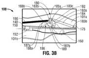
ここで図3A〜図3Cを参照すると、鉗子100のトリガアセンブリ180は、トリガ160と、旋回リンク機構182と、棒リンク機構184と、妨害部材186と、付勢ばね190とを含む。トリガ160は、旋回リンク機構182の第1の端部183aに旋回可能に連結される。旋回リンク機構182は、旋回リンク機構182の第2の端部183bにおいて棒リンク機構184の第1の端部185aに旋回可能に連結される。図3Aに示されるように、付勢ばね190は、下記に詳細に説明されるように、旋回リンク機構182および従ってトリガ160が第1の位置または引き込まれた位置に付勢されるように旋回リンク機構182の第2の端部183bに係合される。棒リンク機構184は、トリガアセンブリ180から遠位に延び、最終的に棒リンク機構184の第2の端部185bにおいてブレード175を係合する。妨害部材186は、ピボット189の周りに旋回可能であり、近位端187aと、遠位端187bとを含み、近位端187aはそこから延びる突出部188aを含み、遠位端187bはそこから延びる突出部188bを含む。 Referring now to FIGS. 3A-3C, the
図3Aに示されるように、トリガアセンブリ180は、ジョー部材110、120の開放位置または間隔を空けた位置(図1)に対応する第1の静止位置に配置される。トリガアセンブリ180の第1の位置において、トリガ160および旋回リンク機構182は、ブレード175が鉗子100のシャフト部材101a内に完全に配置される最近位位置に棒リンク機構184が配置されるように引き込まれた位置に配置されるか、またはジョー部材110の組織係合表面112およびジョー部材120の組織係合表面122に少なくとも近位に配置される。さらに、ジョー部材110、120(図1)が開放位置である場合、図3Aに示されるように妨害部材186の遠位端187bにおける突出部188bは、旋回リンク機構182の凹所183c内に配置され、旋回機構182が旋回しないようにし、その結果、ブレードチャネル170を通ってブレード175を前進させる拡張された位置にトリガ160が回転させない(図2)。より一般的に表現すると、妨害部材186は、ロッキング機構として機能を果たし、ジョー部材110、120(図1)が開放位置である場合、ブレード175を展開させない。妨害部材186は、この「ロックされた」位置の方に付勢され得る。下記に説明されるように、妨害部材186は、ブレードチャネル170の中にブレード175を展開することを可能にして(図2)、ジョー部材110、120(図1)が閉鎖位置に動かされた場合ジョー部材110と120との間に配置された組織を切るように(図1)構成される。 As shown in FIG. 3A, the
ここで図3Bを参照すると、図3Bは、鉗子100を示し、ここで、シャフト部材101a、101bは、互いに接近させられて、ジョー部材110、120(図1)を閉鎖位置に動かす。上記に考察されたように、ジョー部材110、120(図1)が閉鎖位置に動くと、シャフト部材101aから延びるタブ140は、シャフト部材101bの凹所150の中に前進させられる。例えば所定の閉鎖力(または閉鎖力の連続)がジョー部材110、120に加えられるなど、ジョー部材110、120がさらに接近すると、タブ140は、凹所150の中にさらに押し込まれて、アクチュエータ152を押し下げ、ジョー部材110と120との間に掴まれた組織500を密閉するために(図1)ジョー部材110、120の密閉表面112、122(図1)に電気エネルギーを供給する(またはトリガまたは他のスイッチによってユーザが選択可能に供給することを可能にする)。アクチュエータ152は、所定の時間長(length of time)(固定の時間長または調整可能時間長にいずれか)の間ジョー部材110、120の密閉表面112、122に電気外科エネルギーを供給し(図1)、適切に組織密閉を形成するように構成され得る。あるいは、ジョー部材110、120に加えられる所定の閉鎖力(または閉鎖力の連続)(図1)が維持されている限り、アクチュエータ152は、押し下げられたとき、密閉表面112、122に電気外科エネルギーを連続的に供給するように構成され得る(図1)。再び、アクチュエータ152は、単に、ジョー部材110、120(図1)が閉じられているときのみエネルギー送達を可能にする電気トグルスイッチとしてふるまい得る。 Referring now to FIG. 3B, FIG. 3B shows the
図3Bに示されるように、シャフト部材101a、101bが接近すると、シャフト部材101bの外側表面は、妨害部材186の近位端187aにおいて突出部188aに接触し、右回りの方向にピボット189の周りに妨害部材186を回転させる。妨害部材186が回転させられると、妨害部材186の遠位端187bにおける突出部188bは、旋回リンク機構182の凹所183cから係合を解除される。従って、妨害部材186の突出部188bが旋回リンク機構182内に規定される凹所183cから出るように動かされると、旋回リンク機構182およびトリガ160は、「ロック解除される」か、または回転が可能にされる。従って、ジョー部材110、120(図1)がロック解除の位置において、トリガ160は、ジョー部材110と120との間でブレード175を遠位に前進させるように回転させられて、ジョー部材110と120との間に配置される組織500を切り得る(図1)。しかしながら、この時点において付勢ばね190によりトリガ160およびブレード175は、引き込まれた位置のままである。 As shown in FIG. 3B, when the
ここで図3Cを見ると、一旦電気外科エネルギーがジョー部材110の密閉表面112とジョー部材120の密閉表面122(図1)との間に掴まれる組織500を通って伝導されて(図1)、組織500を密閉すると(図1)(または単に、組織を掴み分離することが所望される場合)、ブレード175は、ブレードチャネル170を通って前進させられて(図2)、ジョー部材110と120との間に掴まれる組織500(図1)を切り得る(図1)。より詳細には、チャネル170の中にブレード175を前進させるために、トリガ160は、右回り方向に回転させられる。トリガ160の回転は、付勢ばね190の付勢に対抗して、旋回リンク機構182の同様の右回り回転を引き起こす。旋回リンク機構182が回転させられると、旋回リンク機構182の第2の端部または近位端183bは遠位に動かされ、棒リンク機構184が旋回リンク機構182の第2の端部183bに連結されるので、棒リンク機構184もまた遠位に移動させられる。棒リンク機構184の遠位の移動は、次にシャフト部材101aからブレードチャネル170の中へのブレード175の遠位の移動を引き起こす(図2)。換言すると、トリガ160の回転は、旋回リンク機構182を回転させ、旋回リンク機構182の回転は、次に棒リンク機構184を遠位に前進させ、その結果、ブレード175は、ジョー部材110内に規定されるブレードチャネル170の中に前進させられて(図2)、ジョー部材110と120との間に掴まれる組織500を切る(図1)。 Turning now to FIG. 3C, once electrosurgical energy is conducted through the
トリガ160を解除すると、旋回リンク機構182は付勢ばね190の付勢によって左回りに回転させられ、その結果、棒リンク機構184およびブレード175はシャフト部材101a内の引き込まれた位置に近位に戻される。換言すると、トリガアセンブリ180は、ブレード175がブレードチャネル170を通って展開された後、自動的に引き込められるように構成される(図2)。この時点で、組織500は密閉され分離されており、ブレード175は引き込まれた位置であり、ジョー部材110、120は、開放位置または間隔を空けた位置に動かされて、組織500を開放し得(図1)、その結果、鉗子100は、外科手術部位から引き込められ得る。シャフト部材101a、101bが互いに離れるように動かされると、妨害部材186は「ロックされた」位置に戻される。より具体的には、シャフト部材101bが妨害部材186の突出部188aから離れるように動かされると、妨害部材186は、左回り方向に回転させられ、その結果、突出部188bは、旋回リンク機構182の凹所183c内に戻り係合するように動かされて、再び「ロックする」か、またはブレード175の展開をさせない。 When the
ここで図4A〜図4Cを見ると、鉗子の別の実施形態、すなわち鉗子200が示される。鉗子200は、上記に考察された鉗子100と類似しており、2つの細長いシャフト部材201a、201bを含み、細長いシャフト部材201aは、細長いシャフト部材201aの遠位端204aに取り付けられるエンドエフェクタアセンブリ209を有し、細長いシャフト部材201bは、細長いシャフト部材201bの遠位端204bに取り付けられるエンドエフェクタアセンブリ209を有する。エンドエフェクタアセンブリ209は、一対の旋回可能に接続された向かい合うジョー部材210、220を含み、互いに対するシャフト部材201a、201bの動きが開放位置と、ジョー部材210と220との間に組織を掴む閉鎖位置との間でジョー部材210、220を旋回させるように構成される。 Turning now to FIGS. 4A-4C, another embodiment of a forceps, namely forceps 200, is shown. The
引き続き図4A〜図4Cを参照すると、ジョー部材210はそこに配置される電導性密閉表面212を含み、ジョー部材220はそこに配置される電導性密閉表面222を含む。電導性密閉表面212、222は、互いに向かい合っており、その結果、起動時、電気外科エネルギーは、ジョー部材210と220との間に掴まれる組織を密閉するために、電導性密閉表面212、222に供給され得る。シャフト部材201bに配置されるアクチュエータ250は、ジョー部材210の密閉表面212およびジョー部材220の密閉表面222への電気外科エネルギーの供給を制御するために提供される。換言すると、アクチュエータ250は、電気外科エネルギーを密閉表面212、222に供給するために選択可能に押し下げ可能である。 With continued reference to FIGS. 4A-4C,
鉗子200は、例えばシャフト部材201aなどの、シャフト部材201a、201bのうちの1つのシャフト部材内に配置されるトリガアセンブリ280に連結されるトリガ260をさらに含む。トリガ260は、ジョー部材210と220との間でブレード275を選択可能に前進させて、ジョー部材210と220との間に掴まれた組織を分離するように構成される。従って、前の実施形態の場合のように、鉗子200は、ブレードチャネル(図示されていない)を含み得、ブレードチャネルは、ジョー部材210、220のうちの1つ(または両方)のジョー部材内に規定され、ジョー部材210と220との間に掴まれた組織を分離するためにブレードチャネルを通ってブレード275の移動を可能にするように構成される。 The
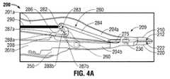
鉗子200のトリガアセンブリ280は、鉗子100のトリガアセンブリ180に類似しており、旋回リンク機構282と、棒リンク機構284と、妨害部材286と、付勢ばね290とを含む。妨害部材286は、近位端287aと、遠位端287bとを含む。妨害部材286の近位端287aは、凹部分288aにシャフト部材201bの突出部208を受けるように構成される凹部分288aを含み、一方、妨害部材286の遠位端287bは、妨害部材286から延びる突出部288bを含む。前の実施形態の場合のように、トリガ260は旋回リンク機構282に連結され、旋回リンク機構282は次に棒リンク機構284に連結される。図4Aに示されるように、付勢ばね290は、旋回リンク機構282およびトリガ260を第1の位置または引き込まれた位置に付勢する。棒リンク機構284は、トリガアセンブリ280から遠位に延びて、ブレード275を係合し、その結果、右回り方向にトリガ260が回転すると、旋回リンク機構282は同様に右回り方向に回転させられ、棒リンク機構284を遠位に前進させ、このことは、次にシャフト部材201aからジョー部材210、220を通って遠位にブレード275を移動させて、ジョー部材210と220との間の組織を切る。 The
ここで図4Aを参照すると、トリガアセンブリ280は、「ロックされた」位置で示され、ここで、妨害部材286の突出部288bは、旋回リンク機構282の凹所283内に係合され、旋回リンク機構282および従ってトリガ260がブレード275を展開するように回転させられない。トリガアセンブリ280のこの「ロックされた」位置は、ジョー部材210、220の開放位置または間隔を空けた位置に対応する。 Referring now to FIG. 4A, the
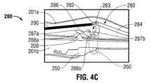
図4Bに示されるように、シャフト部材201a、201bが接近する、すなわち、ジョー部材210、220が閉鎖位置の方に動いて、ジョー部材210と220との間に組織を掴むと、シャフト部材201bから延びる突出部208は、妨害部材286の凹部分288aと係合するように動かされ、妨害部材286が右回り方向に回転するように押し込み、その結果、妨害部材286の突出部288bは、旋回リンク機構282の凹所283から係合解除され、それによって、トリガアセンブリ280の「ロックを解除する」。従って、一旦ジョー部材210、220が接近位置に動かされると、トリガアセンブリ280は「ロックを解除され」、従って、トリガ260は、ジョー部材210と220との間にブレード275を前進させるように回転させられて、ジョー部材210と220との間に掴まれた組織を切り得る。しかしながら、例えばトリガ260が回転する前など、展開の前に、ブレード275は、付勢ばね290の付勢により引き込まれた位置のままである。 As shown in FIG. 4B, when the
ブレード275を前進させて、ジョー部材210と220との間に掴まれた組織を切ることが所望される場合、トリガ260は、右回り方向に回転させられて、旋回リンク機構282を右回り方向に回転させ、このことは次に、棒リンク機構284およびブレード275を遠位に前進させ、その結果、ブレード275は、ジョー部材210と220との間に移動させられて、ジョー部材210と220との間に掴まれる組織を切る。 If it is desired to advance the
トリガ260が解除されると、旋回リンク機構282は、付勢ばね290の付勢により左回り方向に回転させられ、その結果、ブレード275は、シャフト部材201a内において引き込まれた位置に近位に移動させられる。この時点で、ジョー部材210、220は、開放位置または間隔を空けた位置に動かされ得、鉗子200は、外科手術部位から引き込められ得る。シャフト部材201a、201bは、互いに離れるように動かされるので、シャフト部材201bにおける突出部208は、妨害部材386の凹部分288aから係合を解除され、妨害部材286の突出部288bが旋回リンク機構282を係合することを可能にして、トリガアセンブリ280をロックし、ブレード275の展開を妨げる。 When the
本開示に従う鉗子の別の実施形態、すなわち鉗子300は、図5A〜図5Cに示される。鉗子300は、前の実施形態と類似しており、概して一対のシャフト部材301a、301bを含み、シャフト部材301aは、シャフト部材301aの遠位端304aに配置されるエンドエフェクタアセンブリ309を有し、シャフト部材301bは、シャフト部材301bの遠位端304bに配置されるエンドエフェクタアセンブリ309を有する。エンドエフェクタアセンブリ309は、一対のジョー部材310、320を含み、一対のジョー部材310、320は、シャフト部材301a、301bが互いに対して間隔を空けた位置と接近した位置との間で動くと、開放位置と閉鎖位置との間でピボット330の周りに旋回可能である。ジョー部材310はそこに配置される向かい合う電導性密閉表面312を含み得、ジョー部材320はそこに配置される向かい合う電導性密閉表面322を含み得る。電導性密閉表面312、322のうちの1つまたはその両方は、ジョー部材310と320との間に掴まれる組織を密閉するために電気外科エネルギーの供給源(図示されていない)に接続するように適合され得る。 Another embodiment of a forceps according to the present disclosure, ie,
鉗子300は、シャフト部材301aに配置されるトリガ360(但しトリガ360はシャフト部材301bに配置され得る)と、シャフト部材301aに配置されるトリガアエンブリ380とをさらに含む。前の実施形態の場合のように、トリガアセンブリ380は、ブレード375がシャフト部材301a内に配置される引き込まれた位置と、ブレード375がジョー部材310と320との間に延びて、ジョー部材310と320との間に掴まれた組織を切る拡張された位置との間でブレード375を選択可能に移動させるように構成される。 The
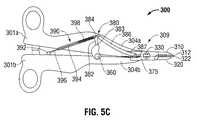
トリガアセンブリ380は、三方(three−way)リンク機構382と、棒リンク機構386と、ピストンアセンブリ390とを含む。三方リンク機構382は、その第1の端部383においてトリガ360に連結され、その第2の端部384において棒リンク機構386およびピストンアセンブリ390の両方に連結される。棒リンク機構386は、三方リンク機構382から遠位に延び、棒リンク機構386の遠位端387においてブレード375と係合される。ピストンアセンブリ390は、三方リンク機構382から近位に延び、シャフト部材301bに配置されるピストンベース392と旋回可能に係合される。ピストンアセンブリ390は、外側シャフト394と、内側シャフト396とをさらに含み、内側シャフト396は、内側シャフト396が外側シャフト394から延びる拡張された位置と、内側シャフト396が実質的に外側シャフト394内に配置される収縮された位置との間で、外側シャフト394内にスライド可能に受容可能である。ピストンアセンブリ390を収縮された位置の方に付勢するように構成される、例えば圧縮ばね398などの付勢部材もまた、提供され得る。
図5B〜図5Cを参照すると、ブレード375を展開するために、ジョー部材310、320は、最初に閉鎖位置に動かされる。次にトリガ360は、右回り方向に回転させられ、このことは次に旋回リンク機構382を右回り方向に回転させる。図5Cに最も良く示されるように、旋回リンク機構382が右回り方向に回転させられると、旋回リンク機構382の第2の端部384は、遠位に動かされ、棒リンク機構386を遠位に移動させる。同時にピストンアセンブリ390は延ばされ、すなわち、内側シャフト396と外側シャフト396は、圧縮ばね398の付勢に対抗して収縮された位置から拡張された位置に動かされる(図5A)。ピストンアセンブリ390の延長は、旋回リンク機構382が右回り方向に回転することを可能にし、従って、旋回リンク機構382の第2の端部384が遠位に動くことを可能にする。旋回リンク機構382の第2の端部384のこの遠位の動きは、棒リンク機構386を遠位に移動させ、このことは、次にシャフト部材301aからジョー部材310、320を通って遠位にブレード375を移動させて、ジョー部材310と320との間に掴まれる組織を切る。 Referring to FIGS. 5B-5C, to deploy
図5Cに示され、上記に言及されるように、ピストンアセンブリ390は、拡張された位置に動かされて、ブレード375が拡張された位置に前進させられることを可能にする。従って、トリガ360が解除されると、ピストンアセンブリ390がピストンアセンブリ390の外側シャフト394内に配置される圧縮ばね398(図5A)の付勢により収縮された位置に戻されるので、ブレード375は引き込まれた位置に戻される。より詳細には、トリガ360が解除されると、圧縮ばね398(図5A)は、収縮された位置に戻るように位置アセンブリ390を付勢し、それによって、旋回リンク機構382の第2の端部384を近位に動かし、このことは、次に、引き込まれた位置に戻るように棒リンク機構386およびブレード375を近位に移動させる。同時に、旋回リンク機構382の第2の端部384の近位の動きは、旋回リンク機構382を左回り方向に回転させ、このことは、次にトリガ360を左回り方向に最初の位置に回転させる(図5B)。より一般的に表現すると、トリガ360が解除されると、ブレード375およびトリガアセンブリ380は、引き込まれた位置に戻される。一旦ブレード375が引き込まれた位置に戻されると、ジョー部材310、320は間隔を空けた位置に動かされ得、鉗子300は外科手術部位から除去され得る。 As shown in FIG. 5C and referred to above, the
しかしながら、トリガ360および/またはブレード375が、拡張された位置で保持されるかまたは動かなくなった場合、ジョー部材310、320が接近位置から間隔を空けた位置に動くと、ピストンアセンブリ390はブレード375を引き込まれた位置に戻し、それによって、ジョー部材110、120が間隔を空けた位置に配置される場合、ブレード375が露出されないことを確実にすることを助ける。より詳細には、上記に言及されるように、ブレード375が拡張された位置である場合、ピストンアセンブリ390は拡張された位置である。拡張された位置である場合、ピストンアセンブリ390はさらに延びるようにはされない。しかしながら、ブレード375が拡張された位置である間、シャフト部材301a、301bを互いに離れるように動かすことは、ピストンアセンブリ390のさらなる延長を必要とする(なぜなら、シャフト部材301a、301bを互いに離れるように動かすことは、ピストンアセンブリ390の一方の端部に取り付けられるピストンベース392と、ピストンアセンブリ390のもう一方の端部に取り付けられる旋回リンク機構382の第2の端部384とを互いに離れるように動かすからである)。従って、例えば接近位置から間隔を空けた位置になど、シャフト部材301a、301bの互いに離れるような動きに適応させるために、ピストンアセンブリ390は、旋回リンク機構382の第2の端部384を近位に引き、それによって、ジョー部材310、320が互いに離れるように動かされると、拡張された位置から引き込まれた位置に戻るようにブレード375を近位に移動させる。そのようなものとして、ジョー部材310、320が接近位置から間隔を空けた位置に動くと、ピストンアセンブリ390は、シャフト301a内の引き込まれた位置にブレード375を戻す。あるいは、ブレード375が拡張された位置に配置される場合、ピストンアセンブリ390は、接近位置から間隔を空けた位置にジョー部材310、320を動かさないように構成され得る。 However, if the
図5Aを参照すると、鉗子300が示され、ここで、シャフト部材301a、301b、および従って、ジョー部材310、320は、開放位置、または間隔を空けた位置に配置される。ジョー部材310、320が開放位置である場合、シャフト部材301aからシャフト部材301bに延びるピストンアセンブリ390は拡張された位置に配置される。拡張された位置において、上記に言及されるように、ピストンアセンブリ390は、さらに延ばされない。その結果、ピストンアセンブリ390は、拡張された位置である場合、旋回リンク機構382を回転させない。すなわち、ピストンアセンブリ390は、旋回リンク機構382の回転時に必要であるように、旋回リンク機構382の第2の端部384を遠位に動かさない。従って、第2の端部384が遠位に動かされないので、リンク機構382はそれによって回転させられないで、トリガ360は次に回転させられない。従って、ピストンアセンブリ390が拡張された位置であるとき、ブレード375は、展開されないか、または開放のジョー部材310、320に延ばされない。 Referring to FIG. 5A,
ジョー部材310、320の開放位置は、ジョー部材310、320が約5度以上の角度で互いに対して斜めに置かれる位置として規定され得るが、但し他の角度は企図される。換言すると、ジョー部材310、320が例えば約5度の角度などの所定の閾値を通り越して互いに離れるように動かされると、ピストンアセンブリ390は拡張された位置に動かされて、ブレード375はジョー部材310と320との間に展開されない。ジョー部材310、320が約5度などの比較的小さい角度で間隔を空けて置かれる場合ピストンアセンブリ390は十分に延ばされない場合があるが、ピストンアセンブリ390は、この位置で十分に延ばされて、ブレード375がジョー部材310、320の中に展開されないように構成され得る。換言すると、この位置においてトリガ360は、部分的に回転させられて(十分に延ばされた位置にピストンアセンブリ390を動かし)、それによって、比較的小さい距離を遠位にブレード375を移動させ得るが、トリガアセンブリ380およびシャフト301aは、上記のように比較的小さい距離を遠位に動かされるにもかかわらず、ブレード375がなおもシャフト301a内に保持され、すなわちブレード375がジョー部材310、320の中に延びないように構成される。他方、ジョー部材310、320が比較的大きな角度で間隔を空けて置かれる場合、ピストンアセンブリ390は、十分に延ばされ得、ブレード375のどの実質的な移動もさせない。 The open position of the
さらに、ジョー部材310、320が接近位置に配置されない場合、シャフト部材301aおよび/またはシャフト部材301bは、ピストンアセンブリ390がさらに延ばされないようにして、それによって、ブレード375が拡張された位置に移動されないようにするロッキング機能(図示されていない)を含み得る。換言すると、ピストンアセンブリ390がさらに延ばされない、接近位置と間隔を空けた位置との間にジョー部材310、320が配置される場合、ロッキング機能(図示されていない)は、ピストンアセンブリ390を係合するように構成され得る。ジョー部材310、320が接近位置と間隔を空けた位置との間に配置される場合のみ、シャフト部材301bのピストンベース392とのピストンアセンブリ390の旋回可能な係合が、そのようなロッキング係合を可能にする。なぜなら、ジョー部材310、320が間隔を空けた位置(または接近位置)に動かされると、ピストンアセンブリ390は、シャフト部材301aおよび/またはシャフト部材301bに対してピストンベース392の周りに旋回させられ、それによって、ロッキング機能(図示されていない)からピストンアセンブリ390を係合解除するからである。ジョー部材310、320が互いに対して比較的小さい距離の間隔を空けて置かれる場合でさえ、そのようなロッキング機能は、ブレード375を露出させない。 Further, if the
図5Bおよび図5Cに示され、上記に考察されたように、ジョー部材310、320が閉鎖位置に動かされる場合、トリガ360は、回転してジョー部材310と320との間にブレード375を展開して、ジョー部材310と320との間の組織を切ることが可能となる。従って、ジョー部材310、320が接近位置または閉鎖位置である場合、ピストンアセンブリ390は、ブレード375の展開を可能にするが、ジョー部材310、320が開放位置である場合、ピストンアセンブリ390は、ブレード375を展開させないで、ジョー部材310、320が開放位置に動かされた場合、引き込まれた位置にブレード375を戻して、ジョー部材310、320が互いに対して間隔を空けて置かれる場合、ブレード375がジョー部材310と320との間に延ばされないかまたは展開されないことを確実にするように助ける。 As shown in FIGS. 5B and 5C and discussed above, when the
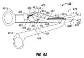
ここで、図6A〜6Cに向けると、鉗子のもう1つの実施形態、鉗子400が示される。鉗子400は、前の実施形態に類似し、2つの細長いシャフト部材401a、401bを含み、細長いシャフト部材401a、401bは、それらのそれぞれの遠位端404a、404bに取り付けられているエンドエフェクタアセンブリ409を有する。エンドエフェクタアセンブリ409は、1対の向かい合うジョー部材410、420を含み、ジョー部材410、420は、間隔を空けた位置と接近位置との間の1つに対するシャフト部材401a、401bの動きに従って、開放位置と閉鎖位置との間に移動可能である。前の実施形態のように、ジョー部材410、420のうちの1つまたは両方は、電気的伝導性密閉表面412、422を含み得、電気的伝導性密閉表面412、422は、ジョー部材410、420の間に掴まれている組織を密閉するために、組織を通って電気外科エネルギーを伝導するように、ジョー部材410、420のそれぞれの反対側の表面上に配置される。 Turning now to FIGS. 6A-6C, another embodiment of a forceps,
鉗子400はまた、シャフト部材401a、401bのうちの1つ(例えば、シャフト部材401a)内に配置されるトリガアセンブリ480に連結されたトリガ460を含む。トリガアセンブリ480は、ブレード475に連結され、ブレード475は、ジョー部材410、420の間に掴まれている組織を切るために、引き込まれた位置から拡張された位置まで選択的に移動可能であり、引き込まれた位置において、ブレード475は、シャフト部材401a内に配置され、拡張された位置において、ブレード475が、例えば、ジョー部材410、420のうちの1つまたは両方内に規定されるブレードチャネル470を通して、ジョー部材410、420の間に延びる。 The
続けて図6A〜6Cに関連して、鉗子400のトリガアセンブリ480は、カンチレバー482を含み、カンチレバー482は、シャフト部材401a内に旋回可能に取り付けられ、かつシャフト部材401a内に規定されるカンチレバーの溝481内に配置される。カンチレバーの溝481は、第1の位置(図6A)と第2の位置(図6C)の間のカンチレバー482の回転を可能にする。付勢部材、例えば、ばね489は、図6Aに示されるように、第1の位置に向かってカンチレバー482を付勢するために提供され得る。棒リンク機構485は、カンチレバー482の第1の端部483に連結され、棒リンク機構485の遠位端487でブレード475を係合するために、棒リンク機構485から遠位に延び、それにより、カンチレバー482は、第1の位置と第2の位置との間に回転されるときに、ブレード475は、引き込まれた位置と拡張された位置との間に移動される。係合凹所486は、カンチレバー482の第2の端部484内に規定される。 With continued reference to FIGS. 6A-6C, the
トリガ460は、シャフト部材401aから延び、かつ遠位位置(図6A)と近位位置(図6C)の間に選択的に移動可能である。付勢部材、例えば、付勢ばね469は、図6Aに示されるように、遠位位置に向かってトリガ460を付勢するために提供され得る。アーム462は、アーム462の近位端463でトリガ460に係合され、シャフト部材401aを通して近位端463から遠位に延びる。フィンガ465は、アーム462の自由な端部464で配置される。フィンガ465は、アーム462から斜めに延び、カンチレバー482の第2の端部484内に規定される係合凹所486を係合するように構成される。以下により詳細に説明されるように、アーム462のフィンガ465とカンチレバー482の係合凹所486との係合で、トリガ460は、ジョー部材410、420の間に掴まれている組織を切るように遠位にブレード475を前進させるために、近位に移動され得る。
ここで、図6Aに関連して、鉗子400が示され、ジョー部材410、420と、シャフト部材401a、401bとは、開放、または間隔を空けた位置に配置される。図6Aに示されるように、付勢ばね489は、第1の位置に向かってカンチレバー482を付勢し、その一方で、付勢ばね469は、遠位位置に向かってトリガ460を付勢する。アーム462のフィンガ465は、カンチレバー482の係合凹所486から間隔を空けられ、または係合解除される。実際には、アーム462は、板ばね、または例えば、フィンガ465が、停止の間にカンチレバー482の係合凹所486から係合解除されるように、図6Aに示される位置において付勢される他のばねのようなメカニズムであり得る。従って、ジョー部材410、420のこの間隔を空けた位置において、カンチレバー482は、第1の位置に配置され、ブレード475は、引き込まれた位置に配置される。さらに、ジョー部材410、420が開放位置にある場合に、トリガ460がトリガアセンブリ480から係合解除されることを用いて、トリガアセンブリ480は、「安全モード」であり、遠位位置から近位位置までのトリガ460の移動は、ブレード475の位置に影響しておらず、すなわち、トリガ460は、トリガアセンブリ480から依存しない。言い換えると、トリガ460が、トリガアセンブリ480から係合解除される場合に、ブレード475が展開されることをさせない。 6A, the
ここで、図6Bに向けると、シャフト部材401a、401bは、例えば、ジョー部材410、420の間の組織を掴むように、ジョー部材410、420を閉鎖位置に動かすために、接近位置に動かされている。図6Bに示されるように、シャフト部材401a、401bの接近で、シャフト部材401bから延びる突出部408は、アーム462のフィンガ465が、カンチレバー482の係合凹所486との係合内に押し込まれるように、カンチレバー482に向かってトリガ460のアーム462を押し込む。この位置において、トリガアセンブリ480は、「アームされる」。しかし、このポイントにおいて、カンチレバー482は、ブレード475が引き込まれた位置に残るように、ばね489の付勢で第1の位置に配置されるように残る。同様に、トリガ460は、ばね469の付勢で遠位位置に残る。 Turning now to FIG. 6B, the
ジョー部材410、420の間の組織を掴む閉鎖位置に配置されるジョー部材410、420と共に、電気外科エネルギーは、ジョー部材410、420の間に掴まれている組織を密閉するために、ジョー部材410、420のそれぞれの密閉表面412および/または密閉表面422に供給され得る。一旦組織が密閉されていると、ブレード475は、先に密閉された組織を分離するために前進され得る。より具体的には、ジョー部材410、420の間に配置されている組織を切ることが望まれる場合に、トリガ460は、図6Cに示されるように、ばね469の付勢に反して、遠位位置から近位位置まで近位に移動される。トリガ460が近位に移動されるときに、アーム462およびフィンガ465は、同様に近位に引っ張られる。従って、アーム462のフィンガ465は、カンチレバー482の係合凹所486内に係合されるので、フィンガ465の近位の引っ張りは、ばね489の付勢に反して、第1の位置から第2の位置までカンチレバーの溝481内にカンチレバー482の回転をもたらす。カンチレバー482は、第2の位置へ回転されるときに、棒リンク機構485は、遠位に移動され、次に、ブレード475は、ジョー部材410、420の間に掴まれている組織を切るために、シャフト401aからジョー部材420内に規定されるブレードチャネル470内に遠位に前進される。 Together with the
一旦ブレード475が、ジョー部材410、420の間の組織を切るために、例えば、ジョー部材410、420の間の拡張された位置に展開されていると、ブレード475が引き込まれた位置に戻されるように、トリガ460がばね469の付勢で遠位位置に戻ることを可能にさせ、そしてカンチレバー482がばね489の付勢で第1の位置に戻ることを可能にさせ、トリガ460は解放され得る。 Once
カンチレバー482の係合溝486は、(ブレード475が拡張された位置へ移動される)第2の位置へのカンチレバー482の回転で、フィンガ485が係合溝486から解放され、または係合溝486との係合から離れて落ち、カンチレバー482と、従ってブレード475とが、(トリガ460の相対的な位置にかかわらず)ばね489の付勢で第1または引き込まれた位置に戻ることを可能にするように構成され得る。代替的に、またはさらに、一旦ブレード475が、ジョー部材410、420の間に配置されている組織を切るために、拡張された位置に展開されていると、ユーザは、ジョー部材410、420を開放位置に動かすために、間隔を空けた位置にシャフト部材401a、401bを動かし得る。シャフト部材401a、401bは、間隔を空けた位置に動かされるときに、シャフト部材401bから延びる突出部408は、アーム462から離れて動かされ、アーム462が、カンチレバー482から間隔を空けられたアーム462の付勢された位置、または停止位置に戻ることを可能にする。従って、開放位置へのシャフト部材401a、401bの動きで、アーム462は、カンチレバー482の係合溝486から係合解除され、カンチレバー482と、従ってブレード475とが、ばね489の付勢で第1または引き込まれた位置に戻ることを可能にする。鉗子400が開放位置に配置されていることと、ブレード475がシャフト401a内に引き込まれていることとを用いて、鉗子400は、外科手術部位から除去され得る。 The
ここで図7A〜7Cに関連して、鉗子100(図1)に類似して、鉗子600のもう1つの実施形態が示される。鉗子600は、第1のシャフト部材601aと第2のシャフト部材601bとを含み、第1のシャフト部材601aと第2のシャフト部材601bとは、それぞれの遠位端でエンドエフェクタアセンブリ、例えばエンドエフェクタアセンブリ109(図1)を係合するように構成される。前の実施形態のように、シャフト部材601a、601bは、組織を掴み、そして/または密閉するために、間隔を空けた位置と接近位置との間にエンドエフェクタアセンブリ109(図1)のジョー部材110、120(図1)を動かすために、互いに対して移動可能である。鉗子600は、ジョー部材110、120(図1)の間に掴まれている組織を分離するために、ジョー部材110、120の間にブレード675(図7B)を選択的に前進させるためのトリガアセンブリ680に連結されたトリガ660をさらに含む。 7A-7C, another embodiment of a
トリガアセンブリ680は、鉗子100のトリガアセンブリ180(図3A〜3Cを参照)に類似し、概ね旋回リンク機構682、棒リンク機構684、妨害部材686、および付勢ばね690を含む。しかし、トリガアセンブリ680は、図7Aに最もよく示されるように、トリガアセンブリ680が、シャフト部材601a内に位置決めされるカバープレート650をさらに含みことで、トリガアセンブリ180(図3A〜3C)と異なる。カバープレート650は、シャフト部材601aに係合され、トリガ660のピボットピン(はっきり示されていない)、旋回リンク機構682、および妨害部材686を固定し、トリガ660、旋回リンク機構682、および妨害部材686が、シャフト部材601aおよびカバープレート650に対して回転することを可能にする。カバープレート650は、近位部分をさらに含み、近位部分は、そこから遠位に延びるリーフばね652(または他の付勢部材)を含む。リーフばね652は、その遠位端653でカバープレート650に係合され、その遠位端654で配置される突出部656を含む。図7Aおよび図7Bに示されるように、リーフばね652は、突出部656がシャフト部材601aからシャフト部材601bに向かって延びるように付勢する。この位置において、突出部656にしっかり係合されているピン658は、妨害部材686内に規定されるスロット688の近位端に配置される。突出部656は、カバープレート650のリーフばね652に係合されると示されるが、突出部656は、代替的にシャフト部材601b上に配置され得る。 The
ここで図7Bに向けると、カバープレート650の遠位部分は、トリガアセンブリ680の下にある部品を示すために除去されている。図7Bに示されるように、シャフト部材601a、601bは、エンドエフェクタアセンブリ109(図1)のジョー部材110、120の間隔を空けた位置に対応して、互いに間隔を空けられている。この位置において、突出部656は、その停止位置に向かってリーフばね652によって付勢される(シャフト部材601aからシャフト部材601bに向かって延びる)。前述のように、突出部656がその停止位置に向かって付勢されることを用いて、ピン658は、妨害部材686内に規定されるスロット688の近位端での位置に保持され、それにより、妨害部材686は、旋回リンク機構682との係合において回転可能に固定される。より具体的に、突出部656は、停止位置に配置される場合に、妨害部材686を位置に維持し、それにより、妨害部材686の遠位係合表面687は、旋回リンク機構682の近位係合表面683と係合され、旋回リンク機構682の回転をさせない。従って、妨害部材686が旋回リンク機構682の回転をさせないことを用いて、トリガ660が回転されることをさせず、ブレード675が展開されることをさせない。言い換えると、シャフト部材601a、601bが、互いから間隔を空けられている場合に、従って、ジョー部材110、120(図1)が、間隔を空けた位置に配置される場合に、ブレード675が展開されることをさせない。 Turning now to FIG. 7B, the distal portion of the
ここで、図7Cに向けると、シャフト部材601a、601bの接近で、例えば、接近位置に向かってジョー部材110、120(図1)を動かすことで、シャフト部材601bは、結果的に、最初にシャフト部材601aからシャフト部材601bに向かって延びる突出部656と接触する。シャフト部材601a、601bは、互いに対してさらに接近するとき、シャフト部材601bは、突起部656を上に向きでシャフト部材601a内に戻るように押し込む。より具体的には、シャフト部材601bが突出部656と接触するときに、リーフばね652は、その停止位置からそらせられ、突出部656は、リーフばね652の付勢に反して、上向きでシャフト部材601b内に動かされる。突出部656は、上向きでシャフト部材601b内に移動されるときに、妨害部材686は、妨害部材686のスロット688内の突出部656のピン658の係合のために、時計回り方向で回転される。同時に、ピン658は、スロット688に沿ってピン658の遠位端に移動される。突起部656のこの上向きの動きの結果として、妨害部材686と、従って妨害部材686の遠位係合表面687は、時計回りに回転され、それにより、妨害部材686の遠位係合表面687は、図7Cに示されるように、旋回リンク機構682の近位係合表面683から係合解除される。この位置において、旋回リンク機構682は、回転することをさせられ、従って、トリガ660は、棒リンク機構684を遠位に前進させるために、旋回リンク機構682を回転するように作動させられ得る。棒リンク機構684が遠位に前進される時に、ブレード675(図7B)は、ジョー部材110、120の間に掴まれている組織を分離するために、シャフト部材601bから遠位に、かつジョー部材110、120(図1)の間に移動される。 Turning now to FIG. 7C, with the approach of the
トリガ660の解放で、ブレード675は、付勢ばね690の付勢で、シャフト部材601a内に戻るように、自動的に近位に引き込まれる。その後は、ジョー部材110、120(図1)は、間隔を空けた位置に動かされ得、鉗子600は、外科手術部位から引かれ得る。シャフト部材601a、601bは、例えば、ジョー部材110、120(図1)を、間隔を空けた位置に動かすために、互いから離れて動かされるときに、シャフト601bは、突出部656から離れて動かされ、突出部656がリーフばね652の付勢でその停止位置に戻ることを可能にする。突出部656の停止位置への戻りは、妨害部材686が反時計周りで回転されるように、妨害部材686に対して、スロット688に沿って下向きで近位にピボットピン658を押し込む。妨害部材686のこの反時計周りの回転は、妨害部材686の遠位係合表面687の類似な回転をもたらし、それにより、遠位係合表面687は、トリガアセンブリ680をロックするために、旋回リンク機構682の近位係合表面683との係合内に回転し戻され、そしてブレード675の展開を妨げる。より一般的に書くと、トリガアセンブリ680は、ジョー部材110、120(図1)が間隔を空けた位置に配置される場合に、ブレード675が展開されることをさせず、ジョー部材110、120(図1)が接近位置に動かされる場合に、ブレード675の展開を可能にする。 Upon release of the
上記さまざまな図面から、そしてそれらの図面に関連して、当業者は、本開示の範囲から逸脱することなしに、一定の変更が本開示にも加えられ得ることを認識する。本開示のいくつかの実施形態は、図面に示されるが、本開示が当技術分野に可能な範囲と同じ広さであり、本明細書が同様に読まれることを意図されるように、本開示が、上記実施形態に限定されることは意図されない。それゆえに、上記の説明は、限定する実施形態としてではなく、むしろ単に特定の実施形態の代表的な例として解釈されるべきである。当業者は、本開示に添付の請求項の範囲および精神内に他の変更を考えられる。 From the various figures above and in connection with those figures, those skilled in the art will recognize that certain changes may be made to the present disclosure without departing from the scope of the present disclosure. Some embodiments of the present disclosure are shown in the drawings, but as this disclosure is as broad as possible in the art, the present specification is intended to be read similarly. It is not intended that the disclosure be limited to the above embodiment. Therefore, the above description should not be construed as limiting, but merely as exemplifications of particular embodiments. Those skilled in the art will envision other modifications within the scope and spirit of the claims appended hereto.
100 鉗子
101a シャフト部材
102a 近位端
104a 遠位端
109 エンドエフェクタアセンブリ
110 ジョー部材
112 密閉表面
120 ジョー部材
160 トリガ
175 切断ブレード
180 トリガアセンブリ
182 旋回リンク機構
186 妨害部材
188a 突出部
500 組織DESCRIPTION OF
Claims (15)
Translated fromJapanese第1のシャフト部材および第2のシャフト部材であって、該第1のシャフト部材および第2のシャフト部材は、それぞれ、該シャフト部材の遠位端に配置されているジョー部材を有し、該ジョー部材のうちの少なくとも1つは、開放位置から、該ジョー部材の間の組織を掴むための閉鎖位置まで移動可能であり、該ジョー部材のうちの少なくとも1つは、該ジョー部材を通るブレードの往復運動のために構成される、第1のシャフト部材および第2のシャフト部材と、
引き込まれた位置と拡張された位置との間で該ブレードを選択的に移動するように構成されるトリガアセンブリであって、該ブレードは、該拡張された位置において、該少なくとも1つのジョー部材を少なくとも部分的に通って延びる、トリガアセンブリと
を備え、
該トリガアセンブリは、
回転可能なトリガと、
少なくとも1つのリンク機構であって、該少なくとも1つのリンク機構は、第1の端部で該回転可能なトリガに連結され、かつ第2の端部で該ブレードに連結されており、その結果、該トリガの回転が、該引き込まれた位置と該拡張された位置との間での該ブレードの移動をもたらす、少なくとも1つのリンク機構と、
妨害部材であって、該妨害部材は、該ジョー部材が該開放位置にある場合のロックされた位置と、該ジョー部材が該閉鎖位置にある場合のロックされていない位置との間で移動可能であり、該妨害部材は、該ロックされた位置にある場合に、該少なくとも1つのリンク機構を係合して、該引き込まれた位置から該拡張された位置までの該ブレードの移動を抑制するように構成される、妨害部材と
を含む、鉗子。A forceps, the forceps being
A first shaft member and a second shaft member, each of the first shaft member and the second shaft member having a jaw member disposed at a distal end of the shaft member; At least one of the jaw members is movable from an open position to a closed position for grasping tissue between the jaw members, and at least one of the jaw members is a blade that passes through the jaw members. A first shaft member and a second shaft member configured for reciprocal movement of
A trigger assembly configured to selectively move the blade between a retracted position and an expanded position, the blade having the at least one jaw member in the expanded position. A trigger assembly extending at least partially through,
The trigger assembly includes:
A rotatable trigger,
At least one linkage, wherein the at least one linkage is coupled to the rotatable trigger at a first end and to the blade at a second end; At least one linkage wherein rotation of the trigger results in movement of the blade between the retracted position and the expanded position;
An obstruction member, the obstruction member being movable between a locked position when the jaw member is in the open position and an unlocked position when the jaw member is in the closed position. And when the blocking member is in the locked position, it engages the at least one linkage mechanism to inhibit movement of the blade from the retracted position to the expanded position. A forceps comprising: an obstruction member configured.
第1のシャフト部材および第2のシャフト部材であって、該第1のシャフト部材および第2のシャフト部材は、それぞれ、該シャフト部材の遠位端に配置されているジョー部材を有し、該ジョー部材のうちの少なくとも1つは、開放位置から、該ジョー部材の間の組織を掴むための閉鎖位置まで移動可能であり、該ジョー部材のうちの少なくとも1つは、該ジョー部材を通るブレードの往復運動のために構成される、第1のシャフト部材および第2のシャフト部材と、
引き込まれた位置と、拡張された位置との間で該ブレードを選択的に移動させるように構成されるトリガアセンブリであって、該ブレードは、該拡張された位置において、該少なくとも1つのジョー部材を少なくとも部分的に通って延びる、トリガアセンブリと
を備え、
該トリガアセンブリは、
トリガと、
アクチュエータに連結される第1の端部を有し、かつ自由な第2の端部を有するアームと、
カンチレバーであって、該カンチレバーは、該カンチレバー内に係合凹所を規定し、第1の位置と第2の位置との間でピボットの周りで回転可能である、カンチレバーと、
第1の端部で該カンチレバーに連結され、かつ第2の端部で該ブレードに連結されている少なくとも1つのリンク機構と、
該第2のシャフト部材から延びるタブであって、該タブは、該閉鎖位置への該ジョー部材の移動の際に、該カンチレバーの該係合凹所内に該アームの該自由な端部を押し込むように構成され、その結果、該トリガの近位移動は、該引き込まれた位置から該拡張された位置まで該ブレードを遠位に移動させるために、該第1の位置から該第2の位置まで該カンチレバーを回転させる、タブと
を含む、鉗子。A forceps, the forceps being
A first shaft member and a second shaft member, each of the first shaft member and the second shaft member having a jaw member disposed at a distal end of the shaft member; At least one of the jaw members is movable from an open position to a closed position for grasping tissue between the jaw members, and at least one of the jaw members is a blade that passes through the jaw members. A first shaft member and a second shaft member configured for reciprocal movement of
A trigger assembly configured to selectively move the blade between a retracted position and an expanded position, wherein the blade is in the expanded position the at least one jaw member A trigger assembly extending at least partially through
The trigger assembly includes:
Trigger,
An arm having a first end coupled to the actuator and having a free second end;
A cantilever, wherein the cantilever defines an engagement recess in the cantilever and is rotatable about a pivot between a first position and a second position;
At least one linkage coupled to the cantilever at a first end and coupled to the blade at a second end;
A tab extending from the second shaft member that pushes the free end of the arm into the engagement recess of the cantilever upon movement of the jaw member to the closed position Configured so that the proximal movement of the trigger causes the blade to move distally from the retracted position to the expanded position from the first position to the second position. Rotating the cantilever until it includes a tab and a forceps.
Applications Claiming Priority (2)
| Application Number | Priority Date | Filing Date | Title |
|---|---|---|---|
| US12/896,100 | 2010-10-01 | ||
| US12/896,100US9017372B2 (en) | 2010-10-01 | 2010-10-01 | Blade deployment mechanisms for surgical forceps |
Related Child Applications (1)
| Application Number | Title | Priority Date | Filing Date |
|---|---|---|---|
| JP2015121663ADivisionJP6355597B2 (en) | 2010-10-01 | 2015-06-17 | Blade deployment mechanism for surgical forceps |
Publications (2)
| Publication Number | Publication Date |
|---|---|
| JP2012075899Atrue JP2012075899A (en) | 2012-04-19 |
| JP5784446B2 JP5784446B2 (en) | 2015-09-24 |
Family
ID=44862270
Family Applications (4)
| Application Number | Title | Priority Date | Filing Date |
|---|---|---|---|
| JP2011216795AActiveJP5784446B2 (en) | 2010-10-01 | 2011-09-30 | Blade deployment mechanism for surgical forceps |
| JP2015121663AExpired - Fee RelatedJP6355597B2 (en) | 2010-10-01 | 2015-06-17 | Blade deployment mechanism for surgical forceps |
| JP2016137233AWithdrawnJP2016193233A (en) | 2010-10-01 | 2016-07-12 | Blade deployment mechanisms for surgical forceps |
| JP2018073035AWithdrawnJP2018108489A (en) | 2010-10-01 | 2018-04-05 | Blade deployment mechanism for surgical forceps |
Family Applications After (3)
| Application Number | Title | Priority Date | Filing Date |
|---|---|---|---|
| JP2015121663AExpired - Fee RelatedJP6355597B2 (en) | 2010-10-01 | 2015-06-17 | Blade deployment mechanism for surgical forceps |
| JP2016137233AWithdrawnJP2016193233A (en) | 2010-10-01 | 2016-07-12 | Blade deployment mechanisms for surgical forceps |
| JP2018073035AWithdrawnJP2018108489A (en) | 2010-10-01 | 2018-04-05 | Blade deployment mechanism for surgical forceps |
Country Status (5)
| Country | Link |
|---|---|
| US (6) | US9017372B2 (en) |
| EP (2) | EP2436327B1 (en) |
| JP (4) | JP5784446B2 (en) |
| AU (1) | AU2011226838B2 (en) |
| CA (1) | CA2753649C (en) |
Cited By (59)
| Publication number | Priority date | Publication date | Assignee | Title |
|---|---|---|---|---|
| JP2015517329A (en)* | 2012-05-02 | 2015-06-22 | エシコン・エンド−サージェリィ・インコーポレイテッドEthicon Endo−Surgery,Inc. | Electrosurgical device for cutting and coagulation |
| JP2015525610A (en)* | 2012-06-29 | 2015-09-07 | エシコン・エンド−サージェリィ・インコーポレイテッドEthicon Endo−Surgery,Inc. | Lockout mechanism for use with robotic electrosurgical devices |
| JP2016504153A (en)* | 2013-01-29 | 2016-02-12 | エシコン・エンド−サージェリィ・インコーポレイテッドEthicon Endo−Surgery,Inc. | Bipolar electrosurgical hand shear |
| US10010339B2 (en) | 2007-11-30 | 2018-07-03 | Ethicon Llc | Ultrasonic surgical blades |
| US10022567B2 (en) | 2008-08-06 | 2018-07-17 | Ethicon Llc | Devices and techniques for cutting and coagulating tissue |
| US10034684B2 (en) | 2015-06-15 | 2018-07-31 | Ethicon Llc | Apparatus and method for dissecting and coagulating tissue |
| US10034704B2 (en) | 2015-06-30 | 2018-07-31 | Ethicon Llc | Surgical instrument with user adaptable algorithms |
| US10117667B2 (en) | 2010-02-11 | 2018-11-06 | Ethicon Llc | Control systems for ultrasonically powered surgical instruments |
| US10154852B2 (en) | 2015-07-01 | 2018-12-18 | Ethicon Llc | Ultrasonic surgical blade with improved cutting and coagulation features |
| US10179022B2 (en) | 2015-12-30 | 2019-01-15 | Ethicon Llc | Jaw position impedance limiter for electrosurgical instrument |
| US10194973B2 (en) | 2015-09-30 | 2019-02-05 | Ethicon Llc | Generator for digitally generating electrical signal waveforms for electrosurgical and ultrasonic surgical instruments |
| US10201382B2 (en) | 2009-10-09 | 2019-02-12 | Ethicon Llc | Surgical generator for ultrasonic and electrosurgical devices |
| US10226273B2 (en) | 2013-03-14 | 2019-03-12 | Ethicon Llc | Mechanical fasteners for use with surgical energy devices |
| US10245064B2 (en) | 2016-07-12 | 2019-04-02 | Ethicon Llc | Ultrasonic surgical instrument with piezoelectric central lumen transducer |
| US10251664B2 (en) | 2016-01-15 | 2019-04-09 | Ethicon Llc | Modular battery powered handheld surgical instrument with multi-function motor via shifting gear assembly |
| USD847990S1 (en) | 2016-08-16 | 2019-05-07 | Ethicon Llc | Surgical instrument |
| US10278721B2 (en) | 2010-07-22 | 2019-05-07 | Ethicon Llc | Electrosurgical instrument with separate closure and cutting members |
| US10285723B2 (en) | 2016-08-09 | 2019-05-14 | Ethicon Llc | Ultrasonic surgical blade with improved heel portion |
| US10285724B2 (en) | 2014-07-31 | 2019-05-14 | Ethicon Llc | Actuation mechanisms and load adjustment assemblies for surgical instruments |
| US10299810B2 (en) | 2010-02-11 | 2019-05-28 | Ethicon Llc | Rotatable cutting implements with friction reducing material for ultrasonic surgical instruments |
| US10321950B2 (en) | 2015-03-17 | 2019-06-18 | Ethicon Llc | Managing tissue treatment |
| US10335183B2 (en) | 2012-06-29 | 2019-07-02 | Ethicon Llc | Feedback devices for surgical control systems |
| US10335182B2 (en) | 2012-06-29 | 2019-07-02 | Ethicon Llc | Surgical instruments with articulating shafts |
| US10342602B2 (en) | 2015-03-17 | 2019-07-09 | Ethicon Llc | Managing tissue treatment |
| US10349999B2 (en) | 2014-03-31 | 2019-07-16 | Ethicon Llc | Controlling impedance rise in electrosurgical medical devices |
| US10357303B2 (en) | 2015-06-30 | 2019-07-23 | Ethicon Llc | Translatable outer tube for sealing using shielded lap chole dissector |
| US10376305B2 (en) | 2016-08-05 | 2019-08-13 | Ethicon Llc | Methods and systems for advanced harmonic energy |
| US10398466B2 (en) | 2007-07-27 | 2019-09-03 | Ethicon Llc | Ultrasonic end effectors with increased active length |
| US10420580B2 (en) | 2016-08-25 | 2019-09-24 | Ethicon Llc | Ultrasonic transducer for surgical instrument |
| US10420579B2 (en) | 2007-07-31 | 2019-09-24 | Ethicon Llc | Surgical instruments |
| US10426507B2 (en) | 2007-07-31 | 2019-10-01 | Ethicon Llc | Ultrasonic surgical instruments |
| US10433900B2 (en) | 2011-07-22 | 2019-10-08 | Ethicon Llc | Surgical instruments for tensioning tissue |
| US10441345B2 (en) | 2009-10-09 | 2019-10-15 | Ethicon Llc | Surgical generator for ultrasonic and electrosurgical devices |
| US10441308B2 (en) | 2007-11-30 | 2019-10-15 | Ethicon Llc | Ultrasonic surgical instrument blades |
| US10441310B2 (en) | 2012-06-29 | 2019-10-15 | Ethicon Llc | Surgical instruments with curved section |
| US10456193B2 (en) | 2016-05-03 | 2019-10-29 | Ethicon Llc | Medical device with a bilateral jaw configuration for nerve stimulation |
| US10463421B2 (en) | 2014-03-27 | 2019-11-05 | Ethicon Llc | Two stage trigger, clamp and cut bipolar vessel sealer |
| US10485607B2 (en) | 2016-04-29 | 2019-11-26 | Ethicon Llc | Jaw structure with distal closure for electrosurgical instruments |
| US10517627B2 (en) | 2012-04-09 | 2019-12-31 | Ethicon Llc | Switch arrangements for ultrasonic surgical instruments |
| US10524872B2 (en) | 2012-06-29 | 2020-01-07 | Ethicon Llc | Closed feedback control for electrosurgical device |
| US10524854B2 (en) | 2010-07-23 | 2020-01-07 | Ethicon Llc | Surgical instrument |
| US10537352B2 (en) | 2004-10-08 | 2020-01-21 | Ethicon Llc | Tissue pads for use with surgical instruments |
| US10543008B2 (en) | 2012-06-29 | 2020-01-28 | Ethicon Llc | Ultrasonic surgical instruments with distally positioned jaw assemblies |
| US10555769B2 (en) | 2016-02-22 | 2020-02-11 | Ethicon Llc | Flexible circuits for electrosurgical instrument |
| US10575892B2 (en) | 2015-12-31 | 2020-03-03 | Ethicon Llc | Adapter for electrical surgical instruments |
| US10595930B2 (en) | 2015-10-16 | 2020-03-24 | Ethicon Llc | Electrode wiping surgical device |
| US10595929B2 (en) | 2015-03-24 | 2020-03-24 | Ethicon Llc | Surgical instruments with firing system overload protection mechanisms |
| US10639092B2 (en) | 2014-12-08 | 2020-05-05 | Ethicon Llc | Electrode configurations for surgical instruments |
| US10646269B2 (en) | 2016-04-29 | 2020-05-12 | Ethicon Llc | Non-linear jaw gap for electrosurgical instruments |
| USRE47996E1 (en) | 2009-10-09 | 2020-05-19 | Ethicon Llc | Surgical generator for ultrasonic and electrosurgical devices |
| US10702329B2 (en) | 2016-04-29 | 2020-07-07 | Ethicon Llc | Jaw structure with distal post for electrosurgical instruments |
| US10842522B2 (en) | 2016-07-15 | 2020-11-24 | Ethicon Llc | Ultrasonic surgical instruments having offset blades |
| US10881449B2 (en) | 2012-09-28 | 2021-01-05 | Ethicon Llc | Multi-function bi-polar forceps |
| US10893883B2 (en) | 2016-07-13 | 2021-01-19 | Ethicon Llc | Ultrasonic assembly for use with ultrasonic surgical instruments |
| JP2021035497A (en)* | 2014-12-23 | 2021-03-04 | アプライド メディカル リソーシーズ コーポレイション | Bipolar electrosurgical sealer and divider |
| US11020140B2 (en) | 2015-06-17 | 2021-06-01 | Cilag Gmbh International | Ultrasonic surgical blade for use with ultrasonic surgical instruments |
| US11058447B2 (en) | 2007-07-31 | 2021-07-13 | Cilag Gmbh International | Temperature controlled ultrasonic surgical instruments |
| US11266430B2 (en) | 2016-11-29 | 2022-03-08 | Cilag Gmbh International | End effector control and calibration |
| US11324527B2 (en) | 2012-11-15 | 2022-05-10 | Cilag Gmbh International | Ultrasonic and electrosurgical devices |
Families Citing this family (193)
| Publication number | Priority date | Publication date | Assignee | Title |
|---|---|---|---|---|
| US7364577B2 (en) | 2002-02-11 | 2008-04-29 | Sherwood Services Ag | Vessel sealing system |
| ES2262639T3 (en) | 2001-04-06 | 2006-12-01 | Sherwood Services Ag | SHUTTER AND DIVIDER OF GLASSES WITH BUMPER MEMBERS N OCONDUCTIVES. |
| US11229472B2 (en) | 2001-06-12 | 2022-01-25 | Cilag Gmbh International | Modular battery powered handheld surgical instrument with multiple magnetic position sensors |
| US9848938B2 (en) | 2003-11-13 | 2017-12-26 | Covidien Ag | Compressible jaw configuration with bipolar RF output electrodes for soft tissue fusion |
| US7367976B2 (en) | 2003-11-17 | 2008-05-06 | Sherwood Services Ag | Bipolar forceps having monopolar extension |
| US8182501B2 (en) | 2004-02-27 | 2012-05-22 | Ethicon Endo-Surgery, Inc. | Ultrasonic surgical shears and method for sealing a blood vessel using same |
| US7628791B2 (en) | 2005-08-19 | 2009-12-08 | Covidien Ag | Single action tissue sealer |
| CA2561034C (en) | 2005-09-30 | 2014-12-09 | Sherwood Services Ag | Flexible endoscopic catheter with an end effector for coagulating and transfecting tissue |
| US20070191713A1 (en) | 2005-10-14 | 2007-08-16 | Eichmann Stephen E | Ultrasonic device for cutting and coagulating |
| US7621930B2 (en) | 2006-01-20 | 2009-11-24 | Ethicon Endo-Surgery, Inc. | Ultrasound medical instrument having a medical ultrasonic blade |
| US8142461B2 (en) | 2007-03-22 | 2012-03-27 | Ethicon Endo-Surgery, Inc. | Surgical instruments |
| US8911460B2 (en) | 2007-03-22 | 2014-12-16 | Ethicon Endo-Surgery, Inc. | Ultrasonic surgical instruments |
| US8808319B2 (en) | 2007-07-27 | 2014-08-19 | Ethicon Endo-Surgery, Inc. | Surgical instruments |
| EP2217157A2 (en) | 2007-10-05 | 2010-08-18 | Ethicon Endo-Surgery, Inc. | Ergonomic surgical instruments |
| ES2442241T3 (en) | 2008-03-31 | 2014-02-10 | Applied Medical Resources Corporation | Electrosurgical system with a switching mechanism |
| US8142473B2 (en) | 2008-10-03 | 2012-03-27 | Tyco Healthcare Group Lp | Method of transferring rotational motion in an articulating surgical instrument |
| US8114122B2 (en) | 2009-01-13 | 2012-02-14 | Tyco Healthcare Group Lp | Apparatus, system, and method for performing an electrosurgical procedure |
| US8187273B2 (en) | 2009-05-07 | 2012-05-29 | Tyco Healthcare Group Lp | Apparatus, system, and method for performing an electrosurgical procedure |
| US9700339B2 (en) | 2009-05-20 | 2017-07-11 | Ethicon Endo-Surgery, Inc. | Coupling arrangements and methods for attaching tools to ultrasonic surgical instruments |
| US8246618B2 (en) | 2009-07-08 | 2012-08-21 | Tyco Healthcare Group Lp | Electrosurgical jaws with offset knife |
| US8663220B2 (en) | 2009-07-15 | 2014-03-04 | Ethicon Endo-Surgery, Inc. | Ultrasonic surgical instruments |
| US8133254B2 (en) | 2009-09-18 | 2012-03-13 | Tyco Healthcare Group Lp | In vivo attachable and detachable end effector assembly and laparoscopic surgical instrument and methods therefor |
| US8112871B2 (en) | 2009-09-28 | 2012-02-14 | Tyco Healthcare Group Lp | Method for manufacturing electrosurgical seal plates |
| US11090104B2 (en) | 2009-10-09 | 2021-08-17 | Cilag Gmbh International | Surgical generator for ultrasonic and electrosurgical devices |
| US10172669B2 (en) | 2009-10-09 | 2019-01-08 | Ethicon Llc | Surgical instrument comprising an energy trigger lockout |
| US8486096B2 (en) | 2010-02-11 | 2013-07-16 | Ethicon Endo-Surgery, Inc. | Dual purpose surgical instrument for cutting and coagulating tissue |
| GB2480498A (en) | 2010-05-21 | 2011-11-23 | Ethicon Endo Surgery Inc | Medical device comprising RF circuitry |
| US8672939B2 (en)* | 2010-06-01 | 2014-03-18 | Covidien Lp | Surgical device for performing an electrosurgical procedure |
| US9028495B2 (en) | 2010-06-23 | 2015-05-12 | Covidien Lp | Surgical instrument with a separable coaxial joint |
| US8795269B2 (en) | 2010-07-26 | 2014-08-05 | Covidien Lp | Rotary tissue sealer and divider |
| US8814864B2 (en) | 2010-08-23 | 2014-08-26 | Covidien Lp | Method of manufacturing tissue sealing electrodes |
| US9498278B2 (en) | 2010-09-08 | 2016-11-22 | Covidien Lp | Asymmetrical electrodes for bipolar vessel sealing |
| US9005200B2 (en) | 2010-09-30 | 2015-04-14 | Covidien Lp | Vessel sealing instrument |
| US9017372B2 (en) | 2010-10-01 | 2015-04-28 | Covidien Lp | Blade deployment mechanisms for surgical forceps |
| AU2011308509B8 (en) | 2010-10-01 | 2015-04-02 | Applied Medical Resources Corporation | Electrosurgical instrument |
| US9345534B2 (en) | 2010-10-04 | 2016-05-24 | Covidien Lp | Vessel sealing instrument |
| US9655672B2 (en)* | 2010-10-04 | 2017-05-23 | Covidien Lp | Vessel sealing instrument |
| US8932293B2 (en) | 2010-11-17 | 2015-01-13 | Covidien Lp | Method and apparatus for vascular tissue sealing with reduced energy consumption |
| US8945175B2 (en) | 2011-01-14 | 2015-02-03 | Covidien Lp | Latch mechanism for surgical instruments |
| US9113940B2 (en) | 2011-01-14 | 2015-08-25 | Covidien Lp | Trigger lockout and kickback mechanism for surgical instruments |
| US8900232B2 (en) | 2011-05-06 | 2014-12-02 | Covidien Lp | Bifurcated shaft for surgical instrument |
| US8939972B2 (en) | 2011-05-06 | 2015-01-27 | Covidien Lp | Surgical forceps |
| US8685009B2 (en) | 2011-05-16 | 2014-04-01 | Covidien Lp | Thread-like knife for tissue cutting |
| US8852185B2 (en) | 2011-05-19 | 2014-10-07 | Covidien Lp | Apparatus for performing an electrosurgical procedure |
| US9615877B2 (en) | 2011-06-17 | 2017-04-11 | Covidien Lp | Tissue sealing forceps |
| US9039704B2 (en)* | 2011-06-22 | 2015-05-26 | Covidien Lp | Forceps |
| US9039732B2 (en)* | 2011-07-11 | 2015-05-26 | Covidien Lp | Surgical forceps |
| US8745840B2 (en) | 2011-07-11 | 2014-06-10 | Covidien Lp | Surgical forceps and method of manufacturing thereof |
| US8852186B2 (en) | 2011-08-09 | 2014-10-07 | Covidien Lp | Microwave sensing for tissue sealing |
| US8845636B2 (en) | 2011-09-16 | 2014-09-30 | Covidien Lp | Seal plate with insulation displacement connection |
| US8864795B2 (en) | 2011-10-03 | 2014-10-21 | Covidien Lp | Surgical forceps |
| US9314295B2 (en) | 2011-10-20 | 2016-04-19 | Covidien Lp | Dissection scissors on surgical device |
| US8968308B2 (en) | 2011-10-20 | 2015-03-03 | Covidien Lp | Multi-circuit seal plates |
| US9492221B2 (en) | 2011-10-20 | 2016-11-15 | Covidien Lp | Dissection scissors on surgical device |
| US9333025B2 (en) | 2011-10-24 | 2016-05-10 | Ethicon Endo-Surgery, Llc | Battery initialization clip |
| USD680220S1 (en) | 2012-01-12 | 2013-04-16 | Coviden IP | Slider handle for laparoscopic device |
| WO2013119545A1 (en) | 2012-02-10 | 2013-08-15 | Ethicon-Endo Surgery, Inc. | Robotically controlled surgical instrument |
| US8747434B2 (en) | 2012-02-20 | 2014-06-10 | Covidien Lp | Knife deployment mechanisms for surgical forceps |
| AU2013230575B2 (en) | 2012-03-08 | 2017-01-19 | Covidien Lp | Vessel sealing instrument |
| US20140005705A1 (en) | 2012-06-29 | 2014-01-02 | Ethicon Endo-Surgery, Inc. | Surgical instruments with articulating shafts |
| US20140005702A1 (en) | 2012-06-29 | 2014-01-02 | Ethicon Endo-Surgery, Inc. | Ultrasonic surgical instruments with distally positioned transducers |
| US9820768B2 (en) | 2012-06-29 | 2017-11-21 | Ethicon Llc | Ultrasonic surgical instruments with control mechanisms |
| US9192421B2 (en) | 2012-07-24 | 2015-11-24 | Covidien Lp | Blade lockout mechanism for surgical forceps |
| US9095367B2 (en) | 2012-10-22 | 2015-08-04 | Ethicon Endo-Surgery, Inc. | Flexible harmonic waveguides/blades for surgical instruments |
| US9375205B2 (en) | 2012-11-15 | 2016-06-28 | Covidien Lp | Deployment mechanisms for surgical instruments |
| US10772674B2 (en) | 2012-11-15 | 2020-09-15 | Covidien Lp | Deployment mechanisms for surgical instruments |
| US9498281B2 (en)* | 2012-11-27 | 2016-11-22 | Covidien Lp | Surgical apparatus |
| AU2013375909B2 (en) | 2013-08-07 | 2015-07-30 | Covidien Lp | Bipolar surgical instrument |
| US10499975B2 (en)* | 2013-08-07 | 2019-12-10 | Covidien Lp | Bipolar surgical instrument |
| US9814514B2 (en) | 2013-09-13 | 2017-11-14 | Ethicon Llc | Electrosurgical (RF) medical instruments for cutting and coagulating tissue |
| US9265926B2 (en) | 2013-11-08 | 2016-02-23 | Ethicon Endo-Surgery, Llc | Electrosurgical devices |
| EP3071136B1 (en) | 2013-11-19 | 2018-10-03 | Divyze, Inc. | Surgical multi-tool and method of use |
| GB2521229A (en) | 2013-12-16 | 2015-06-17 | Ethicon Endo Surgery Inc | Medical device |
| GB2521228A (en) | 2013-12-16 | 2015-06-17 | Ethicon Endo Surgery Inc | Medical device |
| US9795436B2 (en) | 2014-01-07 | 2017-10-24 | Ethicon Llc | Harvesting energy from a surgical generator |
| US9554854B2 (en) | 2014-03-18 | 2017-01-31 | Ethicon Endo-Surgery, Llc | Detecting short circuits in electrosurgical medical devices |
| US10092310B2 (en) | 2014-03-27 | 2018-10-09 | Ethicon Llc | Electrosurgical devices |
| US9913680B2 (en) | 2014-04-15 | 2018-03-13 | Ethicon Llc | Software algorithms for electrosurgical instruments |
| WO2015176074A2 (en) | 2014-05-16 | 2015-11-19 | Applied Medical Resources Corporation | Electrosurgical system |
| JP6735272B2 (en) | 2014-05-30 | 2020-08-05 | アプライド メディカル リソーシーズ コーポレイション | Electrosurgical sealing and incision system |
| US10194972B2 (en) | 2014-08-26 | 2019-02-05 | Ethicon Llc | Managing tissue treatment |
| US10660694B2 (en)* | 2014-08-27 | 2020-05-26 | Covidien Lp | Vessel sealing instrument and switch assemblies thereof |
| US10039592B2 (en) | 2014-09-17 | 2018-08-07 | Covidien Lp | Deployment mechanisms for surgical instruments |
| US9987076B2 (en) | 2014-09-17 | 2018-06-05 | Covidien Lp | Multi-function surgical instruments |
| US9918785B2 (en) | 2014-09-17 | 2018-03-20 | Covidien Lp | Deployment mechanisms for surgical instruments |
| US10080605B2 (en) | 2014-09-17 | 2018-09-25 | Covidien Lp | Deployment mechanisms for surgical instruments |
| US9877777B2 (en) | 2014-09-17 | 2018-01-30 | Covidien Lp | Surgical instrument having a bipolar end effector assembly and a deployable monopolar assembly |
| US10111699B2 (en)* | 2014-12-22 | 2018-10-30 | Ethicon Llc | RF tissue sealer, shear grip, trigger lock mechanism and energy activation |
| US10092348B2 (en)* | 2014-12-22 | 2018-10-09 | Ethicon Llc | RF tissue sealer, shear grip, trigger lock mechanism and energy activation |
| US10159524B2 (en) | 2014-12-22 | 2018-12-25 | Ethicon Llc | High power battery powered RF amplifier topology |
| US10245095B2 (en) | 2015-02-06 | 2019-04-02 | Ethicon Llc | Electrosurgical instrument with rotation and articulation mechanisms |
| US10314638B2 (en) | 2015-04-07 | 2019-06-11 | Ethicon Llc | Articulating radio frequency (RF) tissue seal with articulating state sensing |
| US10130410B2 (en)* | 2015-04-17 | 2018-11-20 | Ethicon Llc | Electrosurgical instrument including a cutting member decouplable from a cutting member trigger |
| US11051873B2 (en) | 2015-06-30 | 2021-07-06 | Cilag Gmbh International | Surgical system with user adaptable techniques employing multiple energy modalities based on tissue parameters |
| US10898256B2 (en) | 2015-06-30 | 2021-01-26 | Ethicon Llc | Surgical system with user adaptable techniques based on tissue impedance |
| US11129669B2 (en) | 2015-06-30 | 2021-09-28 | Cilag Gmbh International | Surgical system with user adaptable techniques based on tissue type |
| US11141213B2 (en) | 2015-06-30 | 2021-10-12 | Cilag Gmbh International | Surgical instrument with user adaptable techniques |
| USD844139S1 (en) | 2015-07-17 | 2019-03-26 | Covidien Lp | Monopolar assembly of a multi-function surgical instrument |
| USD844138S1 (en) | 2015-07-17 | 2019-03-26 | Covidien Lp | Handle assembly of a multi-function surgical instrument |
| US10987159B2 (en) | 2015-08-26 | 2021-04-27 | Covidien Lp | Electrosurgical end effector assemblies and electrosurgical forceps configured to reduce thermal spread |
| US10959771B2 (en) | 2015-10-16 | 2021-03-30 | Ethicon Llc | Suction and irrigation sealing grasper |
| US10213250B2 (en) | 2015-11-05 | 2019-02-26 | Covidien Lp | Deployment and safety mechanisms for surgical instruments |
| US10959806B2 (en) | 2015-12-30 | 2021-03-30 | Ethicon Llc | Energized medical device with reusable handle |
| US11229471B2 (en) | 2016-01-15 | 2022-01-25 | Cilag Gmbh International | Modular battery powered handheld surgical instrument with selective application of energy based on tissue characterization |
| US10716615B2 (en) | 2016-01-15 | 2020-07-21 | Ethicon Llc | Modular battery powered handheld surgical instrument with curved end effectors having asymmetric engagement between jaw and blade |
| US12193698B2 (en) | 2016-01-15 | 2025-01-14 | Cilag Gmbh International | Method for self-diagnosing operation of a control switch in a surgical instrument system |
| US11129670B2 (en) | 2016-01-15 | 2021-09-28 | Cilag Gmbh International | Modular battery powered handheld surgical instrument with selective application of energy based on button displacement, intensity, or local tissue characterization |
| US10426543B2 (en)* | 2016-01-23 | 2019-10-01 | Covidien Lp | Knife trigger for vessel sealer |
| US10537381B2 (en) | 2016-02-26 | 2020-01-21 | Covidien Lp | Surgical instrument having a bipolar end effector assembly and a deployable monopolar assembly |
| USD828554S1 (en)* | 2016-03-09 | 2018-09-11 | Covidien Lp | Contoured blade trigger for an electrosurgical instrument |
| USD819815S1 (en)* | 2016-03-09 | 2018-06-05 | Covidien Lp | L-shaped blade trigger for an electrosurgical instrument |
| US10987156B2 (en) | 2016-04-29 | 2021-04-27 | Ethicon Llc | Electrosurgical instrument with electrically conductive gap setting member and electrically insulative tissue engaging members |
| US10856934B2 (en) | 2016-04-29 | 2020-12-08 | Ethicon Llc | Electrosurgical instrument with electrically conductive gap setting and tissue engaging members |
| US10772673B2 (en) | 2016-05-02 | 2020-09-15 | Covidien Lp | Surgical energy system with universal connection features |
| WO2017223113A1 (en)* | 2016-06-21 | 2017-12-28 | Divyze Inc | Surgical multi-tool and method of use |
| US10682154B2 (en) | 2016-08-02 | 2020-06-16 | Covidien Lp | Cutting mechanisms for surgical end effector assemblies, instruments, and systems |
| US10631887B2 (en) | 2016-08-15 | 2020-04-28 | Covidien Lp | Electrosurgical forceps for video assisted thoracoscopic surgery and other surgical procedures |
| US10952759B2 (en) | 2016-08-25 | 2021-03-23 | Ethicon Llc | Tissue loading of a surgical instrument |
| US10751117B2 (en) | 2016-09-23 | 2020-08-25 | Ethicon Llc | Electrosurgical instrument with fluid diverter |
| US11007003B2 (en)* | 2016-11-17 | 2021-05-18 | Covidien Lp | Surgical instruments and methods of manufacturing surgical instruments for performing tonsillectomy, adenoidectomy, and other surgical procedures |
| US10603064B2 (en) | 2016-11-28 | 2020-03-31 | Ethicon Llc | Ultrasonic transducer |
| JP6326609B2 (en)* | 2016-12-01 | 2018-05-23 | コヴィディエン リミテッド パートナーシップ | Bipolar surgical instrument |
| US10881445B2 (en) | 2017-02-09 | 2021-01-05 | Covidien Lp | Adapters, systems incorporating the same, and methods for providing an electrosurgical forceps with clip-applying functionality |
| US11033325B2 (en) | 2017-02-16 | 2021-06-15 | Cilag Gmbh International | Electrosurgical instrument with telescoping suction port and debris cleaner |
| US11540872B2 (en)* | 2017-03-13 | 2023-01-03 | Covidien Lp | Electrosurgical instrument with trigger driven cutting function |
| US10799284B2 (en) | 2017-03-15 | 2020-10-13 | Ethicon Llc | Electrosurgical instrument with textured jaws |
| US11497546B2 (en) | 2017-03-31 | 2022-11-15 | Cilag Gmbh International | Area ratios of patterned coatings on RF electrodes to reduce sticking |
| US11172980B2 (en) | 2017-05-12 | 2021-11-16 | Covidien Lp | Electrosurgical forceps for grasping, treating, and/or dividing tissue |
| US10973567B2 (en)* | 2017-05-12 | 2021-04-13 | Covidien Lp | Electrosurgical forceps for grasping, treating, and/or dividing tissue |
| US11065062B2 (en)* | 2017-05-17 | 2021-07-20 | Covidien Lp | Systems and methods of tracking and analyzing use of medical instruments |
| US10653475B2 (en) | 2017-06-08 | 2020-05-19 | Covidien Lp | Knife lockout for electrosurgical forceps |
| USD843574S1 (en) | 2017-06-08 | 2019-03-19 | Covidien Lp | Knife for open vessel sealer |
| USD854149S1 (en) | 2017-06-08 | 2019-07-16 | Covidien Lp | End effector for open vessel sealer |
| USD854684S1 (en) | 2017-06-08 | 2019-07-23 | Covidien Lp | Open vessel sealer with mechanical cutter |
| US10603117B2 (en) | 2017-06-28 | 2020-03-31 | Ethicon Llc | Articulation state detection mechanisms |
| US10820920B2 (en) | 2017-07-05 | 2020-11-03 | Ethicon Llc | Reusable ultrasonic medical devices and methods of their use |
| US11154348B2 (en) | 2017-08-29 | 2021-10-26 | Covidien Lp | Surgical instruments and methods of assembling surgical instruments |
| US11490951B2 (en) | 2017-09-29 | 2022-11-08 | Cilag Gmbh International | Saline contact with electrodes |
| US11033323B2 (en) | 2017-09-29 | 2021-06-15 | Cilag Gmbh International | Systems and methods for managing fluid and suction in electrosurgical systems |
| US11484358B2 (en) | 2017-09-29 | 2022-11-01 | Cilag Gmbh International | Flexible electrosurgical instrument |
| US11123132B2 (en) | 2018-04-09 | 2021-09-21 | Covidien Lp | Multi-function surgical instruments and assemblies therefor |
| US10828756B2 (en) | 2018-04-24 | 2020-11-10 | Covidien Lp | Disassembly methods facilitating reprocessing of multi-function surgical instruments |
| US10780544B2 (en) | 2018-04-24 | 2020-09-22 | Covidien Lp | Systems and methods facilitating reprocessing of surgical instruments |
| JP7610777B2 (en) | 2018-09-05 | 2025-01-09 | アプライド メディカル リソーシーズ コーポレイション | Electrosurgical Generator Control System |
| US11471211B2 (en) | 2018-10-12 | 2022-10-18 | Covidien Lp | Electrosurgical forceps |
| US11376062B2 (en) | 2018-10-12 | 2022-07-05 | Covidien Lp | Electrosurgical forceps |
| US20210338312A1 (en)* | 2018-10-19 | 2021-11-04 | Conmed Corporation | Scissor style vessel sealer |
| WO2020086534A1 (en) | 2018-10-22 | 2020-04-30 | The Trustees Of Columbia University In The City Of New York | Systems and apparatuses for manipulating bendable allografts |
| US11696796B2 (en) | 2018-11-16 | 2023-07-11 | Applied Medical Resources Corporation | Electrosurgical system |
| US11350982B2 (en) | 2018-12-05 | 2022-06-07 | Covidien Lp | Electrosurgical forceps |
| US11523861B2 (en) | 2019-03-22 | 2022-12-13 | Covidien Lp | Methods for manufacturing a jaw assembly for an electrosurgical forceps |
| US11241269B2 (en) | 2019-04-04 | 2022-02-08 | Cilag Gmbh International | Surgical devices switchable between monopolar functionality and bipolar functionality |
| US11471212B2 (en) | 2019-04-04 | 2022-10-18 | Cilag Gmbh International | Electrosurgical devices with monopolar and bipolar functionality |
| EP4013328A4 (en) | 2019-08-16 | 2023-08-09 | Divyze, Inc. | Electrosurgical energy adapter, electrosurgical energy control, and surgical multi-tool |
| CN110522509A (en)* | 2019-08-30 | 2019-12-03 | 江苏邦士医疗科技有限公司 | A multi-functional scissor-type high-frequency electric knife that can reduce thermal damage |
| US12402934B2 (en) | 2019-09-15 | 2025-09-02 | Covidien Lp | Electrosurgical instrument for grasping, treating, and/or dividing tissue incorporating thermal management feature |
| US11950797B2 (en) | 2019-12-30 | 2024-04-09 | Cilag Gmbh International | Deflectable electrode with higher distal bias relative to proximal bias |
| US11937863B2 (en) | 2019-12-30 | 2024-03-26 | Cilag Gmbh International | Deflectable electrode with variable compression bias along the length of the deflectable electrode |
| US12343063B2 (en) | 2019-12-30 | 2025-07-01 | Cilag Gmbh International | Multi-layer clamp arm pad for enhanced versatility and performance of a surgical device |
| US11779329B2 (en) | 2019-12-30 | 2023-10-10 | Cilag Gmbh International | Surgical instrument comprising a flex circuit including a sensor system |
| US20210196357A1 (en) | 2019-12-30 | 2021-07-01 | Ethicon Llc | Electrosurgical instrument with asynchronous energizing electrodes |
| US11452525B2 (en) | 2019-12-30 | 2022-09-27 | Cilag Gmbh International | Surgical instrument comprising an adjustment system |
| US11696776B2 (en) | 2019-12-30 | 2023-07-11 | Cilag Gmbh International | Articulatable surgical instrument |
| US12076006B2 (en) | 2019-12-30 | 2024-09-03 | Cilag Gmbh International | Surgical instrument comprising an orientation detection system |
| US12114912B2 (en) | 2019-12-30 | 2024-10-15 | Cilag Gmbh International | Non-biased deflectable electrode to minimize contact between ultrasonic blade and electrode |
| US11937866B2 (en) | 2019-12-30 | 2024-03-26 | Cilag Gmbh International | Method for an electrosurgical procedure |
| US11812957B2 (en) | 2019-12-30 | 2023-11-14 | Cilag Gmbh International | Surgical instrument comprising a signal interference resolution system |
| US11660089B2 (en) | 2019-12-30 | 2023-05-30 | Cilag Gmbh International | Surgical instrument comprising a sensing system |
| US12082808B2 (en) | 2019-12-30 | 2024-09-10 | Cilag Gmbh International | Surgical instrument comprising a control system responsive to software configurations |
| US11944366B2 (en) | 2019-12-30 | 2024-04-02 | Cilag Gmbh International | Asymmetric segmented ultrasonic support pad for cooperative engagement with a movable RF electrode |
| US11786294B2 (en) | 2019-12-30 | 2023-10-17 | Cilag Gmbh International | Control program for modular combination energy device |
| US12023086B2 (en) | 2019-12-30 | 2024-07-02 | Cilag Gmbh International | Electrosurgical instrument for delivering blended energy modalities to tissue |
| US20210196362A1 (en) | 2019-12-30 | 2021-07-01 | Ethicon Llc | Electrosurgical end effectors with thermally insulative and thermally conductive portions |
| US11779387B2 (en) | 2019-12-30 | 2023-10-10 | Cilag Gmbh International | Clamp arm jaw to minimize tissue sticking and improve tissue control |
| US12064109B2 (en) | 2019-12-30 | 2024-08-20 | Cilag Gmbh International | Surgical instrument comprising a feedback control circuit |
| US11986201B2 (en) | 2019-12-30 | 2024-05-21 | Cilag Gmbh International | Method for operating a surgical instrument |
| US11684412B2 (en) | 2019-12-30 | 2023-06-27 | Cilag Gmbh International | Surgical instrument with rotatable and articulatable surgical end effector |
| US11786291B2 (en) | 2019-12-30 | 2023-10-17 | Cilag Gmbh International | Deflectable support of RF energy electrode with respect to opposing ultrasonic blade |
| US12053224B2 (en) | 2019-12-30 | 2024-08-06 | Cilag Gmbh International | Variation in electrode parameters and deflectable electrode to modify energy density and tissue interaction |
| US11911063B2 (en) | 2019-12-30 | 2024-02-27 | Cilag Gmbh International | Techniques for detecting ultrasonic blade to electrode contact and reducing power to ultrasonic blade |
| US12336747B2 (en) | 2019-12-30 | 2025-06-24 | Cilag Gmbh International | Method of operating a combination ultrasonic / bipolar RF surgical device with a combination energy modality end-effector |
| US12262937B2 (en) | 2019-12-30 | 2025-04-01 | Cilag Gmbh International | User interface for surgical instrument with combination energy modality end-effector |
| US11622804B2 (en) | 2020-03-16 | 2023-04-11 | Covidien Lp | Forceps with linear trigger mechanism |
| EP3895644A1 (en) | 2020-04-15 | 2021-10-20 | Erbe Elektromedizin GmbH | Surgical instrument |
| US12295641B2 (en) | 2020-07-01 | 2025-05-13 | Covidien Lp | Electrosurgical forceps with swivel action nerve probe |
| US11660109B2 (en) | 2020-09-08 | 2023-05-30 | Covidien Lp | Cutting elements for surgical instruments such as for use in robotic surgical systems |
| EP4000541B1 (en) | 2020-11-12 | 2023-05-03 | Erbe Elektromedizin GmbH | Surgical instrument |
| CN112401980B (en)* | 2020-11-20 | 2021-11-30 | 中国人民解放军陆军军医大学第一附属医院 | Medical hemostatic forceps |
| WO2023068381A1 (en)* | 2021-10-21 | 2023-04-27 | Olympus Corporation | Medical intervention device with versatile handle |
| US11957342B2 (en) | 2021-11-01 | 2024-04-16 | Cilag Gmbh International | Devices, systems, and methods for detecting tissue and foreign objects during a surgical operation |
| US20230181206A1 (en)* | 2021-11-24 | 2023-06-15 | G. Hipp & Sohn GmbH | Surgical Instrument |
| DE102022100924A1 (en) | 2022-01-17 | 2023-07-20 | Aesculap Ag | Caiman Ring Forceps - Manual HF activation |
| CN115607267B (en)* | 2022-10-21 | 2024-03-29 | 南京首量医疗科技有限公司 | Reusable high-frequency electrosurgical closer |
Citations (1)
| Publication number | Priority date | Publication date | Assignee | Title |
|---|---|---|---|---|
| JP2005144193A (en)* | 2003-11-19 | 2005-06-09 | Sherwood Services Ag | Blood vessel sealing instrument for open operation with cutting mechanism |
Family Cites Families (245)
| Publication number | Priority date | Publication date | Assignee | Title |
|---|---|---|---|---|
| US3100489A (en)* | 1957-09-30 | 1963-08-13 | Medtronic Inc | Cautery device |
| US3896283A (en) | 1971-09-01 | 1975-07-22 | Syndyne Corp | Two-stage push button switch |
| SU401367A1 (en) | 1971-10-05 | 1973-10-12 | Тернопольский государственный медицинский институт | BIAKTIVNYE ELECTRO SURGICAL INSTRUMENT |
| DE2415263A1 (en) | 1974-03-29 | 1975-10-02 | Aesculap Werke Ag | Surgical H.F. coagulation probe has electrode tongs - with exposed ends of insulated conductors forming tong-jaws |
| DE2514501A1 (en) | 1975-04-03 | 1976-10-21 | Karl Storz | Bipolar coagulation instrument for endoscopes - has two high frequency electrodes looped over central insulating piece |
| JPS55106B1 (en) | 1975-04-03 | 1980-01-05 | ||
| FR2315286A2 (en) | 1975-06-26 | 1977-01-21 | Lamidey Marcel | H.F. blood coagulating dissecting forceps - with adjustable stops to vary clamping space and circuit making contacts |
| USD249549S (en) | 1976-10-22 | 1978-09-19 | Aspen Laboratories, Inc. | Electrosurgical handle |
| CA1144990A (en)* | 1978-10-06 | 1983-04-19 | Robert H. Hahn | Depilatory tweezer |
| USD263020S (en) | 1980-01-22 | 1982-02-16 | Rau Iii David M | Retractable knife |
| JPS58168310U (en) | 1982-05-07 | 1983-11-10 | オリンパス光学工業株式会社 | Support device with fall prevention mechanism for surgical microscope |
| US4671274A (en) | 1984-01-30 | 1987-06-09 | Kharkovsky Nauchno-Issledovatelsky Institut Obschei I | Bipolar electrosurgical instrument |
| DE3423356C2 (en) | 1984-06-25 | 1986-06-26 | Berchtold Medizin-Elektronik GmbH & Co, 7200 Tuttlingen | Electrosurgical high frequency cutting instrument |
| US4657016A (en) | 1984-08-20 | 1987-04-14 | Garito Jon C | Electrosurgical handpiece for blades, needles and forceps |
| US4661667A (en) | 1984-11-21 | 1987-04-28 | Hosiden Electronics Co., Ltd. | Two-stage locking push switch |
| USD299413S (en) | 1985-07-17 | 1989-01-17 | The Stanley Works | Folding pocket saw handle |
| USD295893S (en) | 1985-09-25 | 1988-05-24 | Acme United Corporation | Disposable surgical clamp |
| USD295894S (en) | 1985-09-26 | 1988-05-24 | Acme United Corporation | Disposable surgical scissors |
| US4659881A (en) | 1986-01-27 | 1987-04-21 | Eastman Kodak Company | Multidome multistage switch assembly |
| JPH055106Y2 (en) | 1986-02-28 | 1993-02-09 | ||
| USD298353S (en) | 1986-05-06 | 1988-11-01 | Vitalmetrics, Inc. | Handle for surgical instrument |
| JPH0540112Y2 (en) | 1987-03-03 | 1993-10-12 | ||
| JPS6424051A (en) | 1987-07-16 | 1989-01-26 | Meisho Koki Kk | Sheet glass having transparency pattern and its production |
| DE8712328U1 (en) | 1987-09-11 | 1988-02-18 | Jakoubek, Franz, 7201 Emmingen-Liptingen | Endoscopy forceps |
| US4931047A (en) | 1987-09-30 | 1990-06-05 | Cavitron, Inc. | Method and apparatus for providing enhanced tissue fragmentation and/or hemostasis |
| JPH04502328A (en) | 1988-12-05 | 1992-04-23 | ザ・トラステイーズ・オブ・コロンビア・ユニヴアーシテイ・イン・ザ・シテイ・オブ・ニユー・ヨーク | Novel derivative of cyclosporin A, antibodies against it and uses thereof |
| DE3937700C2 (en)* | 1989-11-13 | 1998-02-19 | Sutter Hermann Select Med Tech | Bipolar coagulation forceps with switch |
| US5665100A (en) | 1989-12-05 | 1997-09-09 | Yoon; Inbae | Multifunctional instrument with interchangeable operating units for performing endoscopic procedures |
| JP2806511B2 (en) | 1990-07-31 | 1998-09-30 | 松下電工株式会社 | Manufacturing method of sintered alloy |
| US5190541A (en) | 1990-10-17 | 1993-03-02 | Boston Scientific Corporation | Surgical instrument and method |
| JP2951418B2 (en) | 1991-02-08 | 1999-09-20 | トキコ株式会社 | Sample liquid component analyzer |
| USD348930S (en) | 1991-10-11 | 1994-07-19 | Ethicon, Inc. | Endoscopic stapler |
| US6250532B1 (en)* | 1991-10-18 | 2001-06-26 | United States Surgical Corporation | Surgical stapling apparatus |
| USD349341S (en) | 1992-10-28 | 1994-08-02 | Microsurge, Inc. | Endoscopic grasper |
| US5403312A (en) | 1993-07-22 | 1995-04-04 | Ethicon, Inc. | Electrosurgical hemostatic device |
| DE4303882C2 (en) | 1993-02-10 | 1995-02-09 | Kernforschungsz Karlsruhe | Combination instrument for separation and coagulation for minimally invasive surgery |
| GB9309142D0 (en) | 1993-05-04 | 1993-06-16 | Gyrus Medical Ltd | Laparoscopic instrument |
| USD343453S (en) | 1993-05-05 | 1994-01-18 | Laparomed Corporation | Handle for laparoscopic surgical instrument |
| USD354564S (en) | 1993-06-25 | 1995-01-17 | Richard-Allan Medical Industries, Inc. | Surgical clip applier |
| US5709680A (en)* | 1993-07-22 | 1998-01-20 | Ethicon Endo-Surgery, Inc. | Electrosurgical hemostatic device |
| GB9322464D0 (en) | 1993-11-01 | 1993-12-22 | Gyrus Medical Ltd | Electrosurgical apparatus |
| USD358887S (en) | 1993-12-02 | 1995-05-30 | Cobot Medical Corporation | Combined cutting and coagulating forceps |
| DE4403252A1 (en) | 1994-02-03 | 1995-08-10 | Michael Hauser | Instrument shaft for min. invasive surgery |
| GB9413070D0 (en) | 1994-06-29 | 1994-08-17 | Gyrus Medical Ltd | Electrosurgical apparatus |
| USD384413S (en) | 1994-10-07 | 1997-09-30 | United States Surgical Corporation | Endoscopic suturing instrument |
| GB9425781D0 (en) | 1994-12-21 | 1995-02-22 | Gyrus Medical Ltd | Electrosurgical instrument |
| US5559311A (en) | 1994-12-27 | 1996-09-24 | General Motors Corporation | Dual detent dome switch assembly |
| DE19506363A1 (en) | 1995-02-24 | 1996-08-29 | Frost Lore Geb Haupt | Non-invasive thermometry in organs under hyperthermia and coagulation conditions |
| US5510584A (en) | 1995-03-07 | 1996-04-23 | Itt Corporation | Sequentially operated snap action membrane switches |
| DE19515914C1 (en) | 1995-05-02 | 1996-07-25 | Aesculap Ag | Tong or scissor-shaped surgical instrument |
| US6293942B1 (en) | 1995-06-23 | 2001-09-25 | Gyrus Medical Limited | Electrosurgical generator method |
| JPH1024051A (en) | 1995-09-20 | 1998-01-27 | Olympus Optical Co Ltd | Coagulation forceps with separating function |
| DE19608716C1 (en) | 1996-03-06 | 1997-04-17 | Aesculap Ag | Bipolar surgical holding instrument |
| USD416089S (en) | 1996-04-08 | 1999-11-02 | Richard-Allan Medical Industries, Inc. | Endoscopic linear stapling and dividing surgical instrument |
| US5717176A (en) | 1996-07-17 | 1998-02-10 | United Technologies Automotive, Inc. | Sequentially operated membrane switches |
| DE29616210U1 (en) | 1996-09-18 | 1996-11-14 | Olympus Winter & Ibe Gmbh, 22045 Hamburg | Handle for surgical instruments |
| US5923475A (en) | 1996-11-27 | 1999-07-13 | Eastman Kodak Company | Laser printer using a fly's eye integrator |
| US5827279A (en) | 1996-12-06 | 1998-10-27 | Ethicon Endo-Surgery, Inc. | Knife coupler mechanism for an endoscopic instrument |
| US5891142A (en) | 1996-12-06 | 1999-04-06 | Eggers & Associates, Inc. | Electrosurgical forceps |
| USH2037H1 (en) | 1997-05-14 | 2002-07-02 | David C. Yates | Electrosurgical hemostatic device including an anvil |
| DE19738457B4 (en) | 1997-09-03 | 2009-01-02 | Celon Ag Medical Instruments | Method and device for in vivo deep coagulation of biological tissue volumes while sparing the tissue surface with high frequency alternating current |
| USD402028S (en) | 1997-10-10 | 1998-12-01 | Invasatec, Inc. | Hand controller for medical system |
| US5898147A (en) | 1997-10-29 | 1999-04-27 | C & K Components, Inc. | Dual tact switch assembly |
| DE19751108A1 (en) | 1997-11-18 | 1999-05-20 | Beger Frank Michael Dipl Desig | Electrosurgical operation tool, especially for diathermy |
| JPH11169381A (en) | 1997-12-15 | 1999-06-29 | Olympus Optical Co Ltd | High frequency treating device |
| EP0923907A1 (en) | 1997-12-19 | 1999-06-23 | Gyrus Medical Limited | An electrosurgical instrument |
| DE19833600A1 (en)* | 1998-07-25 | 2000-03-02 | Storz Karl Gmbh & Co Kg | Medical forceps with two independently movable jaw parts |
| JP4225624B2 (en)* | 1998-08-27 | 2009-02-18 | オリンパス株式会社 | High frequency treatment device |
| USD449886S1 (en) | 1998-10-23 | 2001-10-30 | Sherwood Services Ag | Forceps with disposable electrode |
| USD424694S (en) | 1998-10-23 | 2000-05-09 | Sherwood Services Ag | Forceps |
| USD425201S (en) | 1998-10-23 | 2000-05-16 | Sherwood Services Ag | Disposable electrode assembly |
| US7267677B2 (en)* | 1998-10-23 | 2007-09-11 | Sherwood Services Ag | Vessel sealing instrument |
| DE19858512C1 (en) | 1998-12-18 | 2000-05-25 | Storz Karl Gmbh & Co Kg | Bipolar medical instrument for minimally invasive surgery for endoscopic operations; has mutually insulated leads passing through tubular shaft to conductor elements on linked jaw parts |
| US6666875B1 (en) | 1999-03-05 | 2003-12-23 | Olympus Optical Co., Ltd. | Surgical apparatus permitting recharge of battery-driven surgical instrument in noncontact state |
| GB9911954D0 (en) | 1999-05-21 | 1999-07-21 | Gyrus Medical Ltd | Electrosurgery system and instrument |
| GB9911956D0 (en) | 1999-05-21 | 1999-07-21 | Gyrus Medical Ltd | Electrosurgery system and method |
| GB9912625D0 (en) | 1999-05-28 | 1999-07-28 | Gyrus Medical Ltd | An electrosurgical generator and system |
| GB9912627D0 (en) | 1999-05-28 | 1999-07-28 | Gyrus Medical Ltd | An electrosurgical instrument |
| GB9913652D0 (en) | 1999-06-11 | 1999-08-11 | Gyrus Medical Ltd | An electrosurgical generator |
| USD465281S1 (en) | 1999-09-21 | 2002-11-05 | Karl Storz Gmbh & Co. Kg | Endoscopic medical instrument |
| DE10003020C2 (en) | 2000-01-25 | 2001-12-06 | Aesculap Ag & Co Kg | Bipolar barrel instrument |
| US6492602B2 (en) | 2000-02-10 | 2002-12-10 | Alps Electric Co., Ltd. | Two-position pushbutton switch |
| US6500169B1 (en) | 2000-05-15 | 2002-12-31 | Stryker Corporation | Powered surgical handpiece with membrane switch |
| DE10027727C1 (en) | 2000-06-03 | 2001-12-06 | Aesculap Ag & Co Kg | Scissors-shaped or forceps-shaped surgical instrument |
| DE10045375C2 (en) | 2000-09-14 | 2002-10-24 | Aesculap Ag & Co Kg | Medical instrument |
| US7273483B2 (en) | 2000-10-20 | 2007-09-25 | Ethicon Endo-Surgery, Inc. | Apparatus and method for alerting generator functions in an ultrasonic surgical system |
| US6303887B1 (en) | 2001-02-23 | 2001-10-16 | Shin-Etsu Polymer Co., Ltd. | Pushbutton switch element for pushbutton switch structure |
| USD454951S1 (en) | 2001-02-27 | 2002-03-26 | Visionary Biomedical, Inc. | Steerable catheter |
| USD466209S1 (en) | 2001-02-27 | 2002-11-26 | Visionary Biomedical, Inc. | Steerable catheter |
| US6774330B2 (en) | 2001-03-27 | 2004-08-10 | Trw Inc. | Multi-stage push button switch apparatus |
| US7083618B2 (en) | 2001-04-06 | 2006-08-01 | Sherwood Services Ag | Vessel sealer and divider |
| US20030229344A1 (en)* | 2002-01-22 | 2003-12-11 | Dycus Sean T. | Vessel sealer and divider and method of manufacturing same |
| USD457958S1 (en) | 2001-04-06 | 2002-05-28 | Sherwood Services Ag | Vessel sealer and divider |
| US7101371B2 (en) | 2001-04-06 | 2006-09-05 | Dycus Sean T | Vessel sealer and divider |
| USD457959S1 (en) | 2001-04-06 | 2002-05-28 | Sherwood Services Ag | Vessel sealer |
| US20030018332A1 (en) | 2001-06-20 | 2003-01-23 | Schmaltz Dale Francis | Bipolar electrosurgical instrument with replaceable electrodes |
| US6747218B2 (en) | 2002-09-20 | 2004-06-08 | Sherwood Services Ag | Electrosurgical haptic switch including snap dome and printed circuit stepped contact array |
| US7244257B2 (en) | 2002-11-05 | 2007-07-17 | Sherwood Services Ag | Electrosurgical pencil having a single button variable control |
| US7799026B2 (en) | 2002-11-14 | 2010-09-21 | Covidien Ag | Compressible jaw configuration with bipolar RF output electrodes for soft tissue fusion |
| USD493888S1 (en) | 2003-02-04 | 2004-08-03 | Sherwood Services Ag | Electrosurgical pencil with pistol grip |
| CA2523675C (en) | 2003-05-01 | 2016-04-26 | Sherwood Services Ag | Electrosurgical instrument which reduces thermal damage to adjacent tissue |
| JP3938760B2 (en) | 2003-05-12 | 2007-06-27 | オリンパス株式会社 | Fluid control input means |
| USD499181S1 (en) | 2003-05-15 | 2004-11-30 | Sherwood Services Ag | Handle for a vessel sealer and divider |
| USD496997S1 (en) | 2003-05-15 | 2004-10-05 | Sherwood Services Ag | Vessel sealer and divider |
| USD502994S1 (en) | 2003-05-21 | 2005-03-15 | Blake, Iii Joseph W | Repeating multi-clip applier |
| USD545432S1 (en) | 2003-08-08 | 2007-06-26 | Olympus Corporation | Distal portion of hemostatic forceps for endoscope |
| USD509297S1 (en) | 2003-10-17 | 2005-09-06 | Tyco Healthcare Group, Lp | Surgical instrument |
| US7367976B2 (en) | 2003-11-17 | 2008-05-06 | Sherwood Services Ag | Bipolar forceps having monopolar extension |
| US7500975B2 (en) | 2003-11-19 | 2009-03-10 | Covidien Ag | Spring loaded reciprocating tissue cutting mechanism in a forceps-style electrosurgical instrument |
| US7252667B2 (en) | 2003-11-19 | 2007-08-07 | Sherwood Services Ag | Open vessel sealing instrument with cutting mechanism and distal lockout |
| US7811283B2 (en) | 2003-11-19 | 2010-10-12 | Covidien Ag | Open vessel sealing instrument with hourglass cutting mechanism and over-ratchet safety |
| US7780662B2 (en) | 2004-03-02 | 2010-08-24 | Covidien Ag | Vessel sealing system using capacitive RF dielectric heating |
| USD541938S1 (en) | 2004-04-09 | 2007-05-01 | Sherwood Services Ag | Open vessel sealer with mechanical cutter |
| DE102004026179B4 (en) | 2004-05-14 | 2009-01-22 | Erbe Elektromedizin Gmbh | Electrosurgical instrument |
| CN1906719A (en) | 2004-06-15 | 2007-01-31 | 日本航空电子工业株式会社 | Dome contact and multistage operating electric switch containing the same |
| USD533942S1 (en) | 2004-06-30 | 2006-12-19 | Sherwood Services Ag | Open vessel sealer with mechanical cutter |
| US7540872B2 (en) | 2004-09-21 | 2009-06-02 | Covidien Ag | Articulating bipolar electrosurgical instrument |
| USD541418S1 (en) | 2004-10-06 | 2007-04-24 | Sherwood Services Ag | Lung sealing device |
| USD525361S1 (en) | 2004-10-06 | 2006-07-18 | Sherwood Services Ag | Hemostat style elongated dissecting and dividing instrument |
| USD531311S1 (en) | 2004-10-06 | 2006-10-31 | Sherwood Services Ag | Pistol grip style elongated dissecting and dividing instrument |
| USD535027S1 (en) | 2004-10-06 | 2007-01-09 | Sherwood Services Ag | Low profile vessel sealing and cutting mechanism |
| USD567943S1 (en) | 2004-10-08 | 2008-04-29 | Sherwood Services Ag | Over-ratchet safety for a vessel sealing instrument |
| USD533274S1 (en) | 2004-10-12 | 2006-12-05 | Allegiance Corporation | Handle for surgical suction-irrigation device |
| USD582038S1 (en) | 2004-10-13 | 2008-12-02 | Medtronic, Inc. | Transurethral needle ablation device |
| USD564662S1 (en) | 2004-10-13 | 2008-03-18 | Sherwood Services Ag | Hourglass-shaped knife for electrosurgical forceps |
| US7909823B2 (en)* | 2005-01-14 | 2011-03-22 | Covidien Ag | Open vessel sealing instrument |
| USD538932S1 (en) | 2005-06-30 | 2007-03-20 | Medical Action Industries Inc. | Surgical needle holder |
| US7837685B2 (en) | 2005-07-13 | 2010-11-23 | Covidien Ag | Switch mechanisms for safe activation of energy on an electrosurgical instrument |
| US7628791B2 (en)* | 2005-08-19 | 2009-12-08 | Covidien Ag | Single action tissue sealer |
| US7722607B2 (en) | 2005-09-30 | 2010-05-25 | Covidien Ag | In-line vessel sealer and divider |
| CA2561034C (en) | 2005-09-30 | 2014-12-09 | Sherwood Services Ag | Flexible endoscopic catheter with an end effector for coagulating and transfecting tissue |
| DE102006042985A1 (en) | 2005-10-04 | 2007-04-19 | Erbe Elektromedizin Gmbh | Electrosurgical instrument for coagulating tissue, has deformable unit arranged on branch or gripping device such that area of gripping device can be moved to actuate switching device when branches are closed and minimum distance is reached |
| US7766910B2 (en) | 2006-01-24 | 2010-08-03 | Tyco Healthcare Group Lp | Vessel sealer and divider for large tissue structures |
| US8298232B2 (en)* | 2006-01-24 | 2012-10-30 | Tyco Healthcare Group Lp | Endoscopic vessel sealer and divider for large tissue structures |
| US8734443B2 (en) | 2006-01-24 | 2014-05-27 | Covidien Lp | Vessel sealer and divider for large tissue structures |
| USD541611S1 (en) | 2006-01-26 | 2007-05-01 | Robert Bosch Gmbh | Cordless screwdriver |
| US7674003B2 (en) | 2006-04-20 | 2010-03-09 | Streamlight, Inc. | Flashlight having plural switches and a controller |
| US20080004608A1 (en) | 2006-06-30 | 2008-01-03 | Alcon, Inc. | Multifunction surgical probe |
| USD547154S1 (en) | 2006-09-08 | 2007-07-24 | Winsource Industries Limited | Rotary driving tool |
| US7738971B2 (en) | 2007-01-10 | 2010-06-15 | Ethicon Endo-Surgery, Inc. | Post-sterilization programming of surgical instruments |
| JP5165696B2 (en) | 2007-01-16 | 2013-03-21 | エシコン・エンド−サージェリィ・インコーポレイテッド | Ultrasonic device for cutting and coagulation |
| USD575395S1 (en) | 2007-02-15 | 2008-08-19 | Tyco Healthcare Group Lp | Hemostat style elongated dissecting and dividing instrument |
| US20080208108A1 (en) | 2007-02-28 | 2008-08-28 | Kenichi Kimura | Treatment apparatus for operation |
| US8215182B2 (en) | 2007-04-26 | 2012-07-10 | Tyco Healthcare Group Lp | Apparatus and method for measuring pressure between jaw members |
| US7905380B2 (en) | 2007-06-04 | 2011-03-15 | Ethicon Endo-Surgery, Inc. | Surgical instrument having a multiple rate directional switching mechanism |
| USD575401S1 (en) | 2007-06-12 | 2008-08-19 | Tyco Healthcare Group Lp | Vessel sealer |
| DE202007009317U1 (en) | 2007-06-26 | 2007-08-30 | Aesculap Ag & Co. Kg | Surgical instrument |
| US8777945B2 (en) | 2007-06-29 | 2014-07-15 | Covidien Lp | Method and system for monitoring tissue during an electrosurgical procedure |
| US8808319B2 (en) | 2007-07-27 | 2014-08-19 | Ethicon Endo-Surgery, Inc. | Surgical instruments |
| US8334468B2 (en) | 2008-11-06 | 2012-12-18 | Covidien Ag | Method of switching a cordless hand-held ultrasonic cautery cutting device |
| GB2467883B (en)* | 2007-12-18 | 2013-02-13 | Bovie Medical Corp | Surgical apparatus with removable tool cartridge |
| JP5496520B2 (en) | 2008-02-14 | 2014-05-21 | エシコン・エンド−サージェリィ・インコーポレイテッド | Motorized cutting and fastening device with control circuit to optimize battery use |
| US8328802B2 (en) | 2008-03-19 | 2012-12-11 | Covidien Ag | Cordless medical cauterization and cutting device |
| US8152806B2 (en)* | 2008-09-11 | 2012-04-10 | Black & Black Surgical, Inc. | Monopolar electrosurgical instrument |
| US7854185B2 (en)* | 2009-01-12 | 2010-12-21 | Tianjin Runshi Science Development Co., Ltd. | Ratchet pliers with adjustable jaw |
| US20100249769A1 (en) | 2009-03-24 | 2010-09-30 | Tyco Healthcare Group Lp | Apparatus for Tissue Sealing |
| US8226650B2 (en) | 2009-03-26 | 2012-07-24 | Tyco Healthcare Group Lp | Apparatus, system, and method for performing an endoscopic electrosurgical procedure |
| US8277446B2 (en)* | 2009-04-24 | 2012-10-02 | Tyco Healthcare Group Lp | Electrosurgical tissue sealer and cutter |
| USD621503S1 (en) | 2009-04-28 | 2010-08-10 | Tyco Healthcare Group Ip | Pistol grip laparoscopic sealing and dissection device |
| US9192430B2 (en) | 2009-05-01 | 2015-11-24 | Covidien Lp | Electrosurgical instrument with time limit circuit |
| US8187273B2 (en) | 2009-05-07 | 2012-05-29 | Tyco Healthcare Group Lp | Apparatus, system, and method for performing an electrosurgical procedure |
| USD617900S1 (en) | 2009-05-13 | 2010-06-15 | Tyco Healthcare Group Lp | End effector tip with undercut bottom jaw |
| USD618798S1 (en) | 2009-05-13 | 2010-06-29 | Tyco Healthcare Group Lp | Vessel sealing jaw seal plate |
| USD617902S1 (en) | 2009-05-13 | 2010-06-15 | Tyco Healthcare Group Lp | End effector tip with undercut top jaw |
| USD617901S1 (en) | 2009-05-13 | 2010-06-15 | Tyco Healthcare Group Lp | End effector chamfered tip |
| USD617903S1 (en) | 2009-05-13 | 2010-06-15 | Tyco Healthcare Group Lp | End effector pointed tip |
| US8292067B2 (en) | 2009-06-09 | 2012-10-23 | Tyco Healthcare Group Lp | Knotless endostitch package |
| US8650728B2 (en) | 2009-06-24 | 2014-02-18 | Ethicon Endo-Surgery, Inc. | Method of assembling a transducer for a surgical instrument |
| US8461744B2 (en) | 2009-07-15 | 2013-06-11 | Ethicon Endo-Surgery, Inc. | Rotating transducer mount for ultrasonic surgical instruments |
| US8343150B2 (en) | 2009-07-15 | 2013-01-01 | Covidien Lp | Mechanical cycling of seal pressure coupled with energy for tissue fusion |
| US8968358B2 (en) | 2009-08-05 | 2015-03-03 | Covidien Lp | Blunt tissue dissection surgical instrument jaw designs |
| US8679115B2 (en) | 2009-08-19 | 2014-03-25 | Covidien Lp | Electrical cutting and vessel sealing jaw members |
| US8287536B2 (en) | 2009-08-26 | 2012-10-16 | Tyco Healthcare Group Lp | Cutting assembly for surgical instruments |
| US8430876B2 (en) | 2009-08-27 | 2013-04-30 | Tyco Healthcare Group Lp | Vessel sealer and divider with knife lockout |
| US20110054471A1 (en) | 2009-08-27 | 2011-03-03 | Tyco Healthcare Group Lp | Apparatus for Performing an Electrosurgical Procedure |
| US20110054468A1 (en) | 2009-09-01 | 2011-03-03 | Tyco Healthcare Group Lp | Apparatus for Performing an Electrosurgical Procedure |
| US8357159B2 (en) | 2009-09-03 | 2013-01-22 | Covidien Lp | Open vessel sealing instrument with pivot assembly |
| US8162965B2 (en)* | 2009-09-09 | 2012-04-24 | Tyco Healthcare Group Lp | Low profile cutting assembly with a return spring |
| US8568412B2 (en) | 2009-09-09 | 2013-10-29 | Covidien Lp | Apparatus and method of controlling cutting blade travel through the use of etched features |
| US8439911B2 (en) | 2009-09-09 | 2013-05-14 | Coviden Lp | Compact jaw including through bore pivot pin |
| US20110060335A1 (en) | 2009-09-10 | 2011-03-10 | Tyco Healthcare Group Lp | Apparatus for Tissue Fusion and Method of Use |
| US8133254B2 (en) | 2009-09-18 | 2012-03-13 | Tyco Healthcare Group Lp | In vivo attachable and detachable end effector assembly and laparoscopic surgical instrument and methods therefor |
| US20110071523A1 (en) | 2009-09-23 | 2011-03-24 | Tyco Healthcare Group Lp | Vessel Sealer with Self-Aligning Jaws |
| US8112871B2 (en) | 2009-09-28 | 2012-02-14 | Tyco Healthcare Group Lp | Method for manufacturing electrosurgical seal plates |
| US8266783B2 (en) | 2009-09-28 | 2012-09-18 | Tyco Healthcare Group Lp | Method and system for manufacturing electrosurgical seal plates |
| US9820806B2 (en) | 2009-09-29 | 2017-11-21 | Covidien Lp | Switch assembly for electrosurgical instrument |
| US9024237B2 (en) | 2009-09-29 | 2015-05-05 | Covidien Lp | Material fusing apparatus, system and method of use |
| US8323310B2 (en) | 2009-09-29 | 2012-12-04 | Covidien Lp | Vessel sealing jaw with offset sealing surface |
| US8512371B2 (en) | 2009-10-06 | 2013-08-20 | Covidien Lp | Jaw, blade and gap manufacturing for surgical instruments with small jaws |
| US8292886B2 (en) | 2009-10-06 | 2012-10-23 | Tyco Healthcare Group Lp | Apparatus, system, and method for performing an electrosurgical procedure |
| US8939974B2 (en)* | 2009-10-09 | 2015-01-27 | Ethicon Endo-Surgery, Inc. | Surgical instrument comprising first and second drive systems actuatable by a common trigger mechanism |
| US8343151B2 (en) | 2009-10-09 | 2013-01-01 | Covidien Lp | Vessel sealer and divider with captured cutting element |
| US8388647B2 (en) | 2009-10-28 | 2013-03-05 | Covidien Lp | Apparatus for tissue sealing |
| US9060798B2 (en) | 2009-11-16 | 2015-06-23 | Covidien Lp | Surgical forceps capable of adjusting sealing pressure based on vessel size |
| US8480671B2 (en) | 2010-01-22 | 2013-07-09 | Covidien Lp | Compact jaw including split pivot pin |
| US8556929B2 (en) | 2010-01-29 | 2013-10-15 | Covidien Lp | Surgical forceps capable of adjusting seal plate width based on vessel size |
| US8858553B2 (en) | 2010-01-29 | 2014-10-14 | Covidien Lp | Dielectric jaw insert for electrosurgical end effector |
| US9585709B2 (en) | 2010-02-05 | 2017-03-07 | Covidien Lp | Square wave for vessel sealing |
| US8808288B2 (en)* | 2010-03-08 | 2014-08-19 | Covidien Lp | Surgical forceps including belt blade reverser mechanism |
| US8740898B2 (en) | 2010-03-22 | 2014-06-03 | Covidien Lp | Surgical forceps |
| US8425511B2 (en) | 2010-03-26 | 2013-04-23 | Covidien Lp | Clamp and scissor forceps |
| EP2425790B1 (en) | 2010-03-31 | 2015-09-30 | Olympus Medical Systems Corp. | Medical system and surgical treatment tool |
| US8961504B2 (en) | 2010-04-09 | 2015-02-24 | Covidien Lp | Optical hydrology arrays and system and method for monitoring water displacement during treatment of patient tissue |
| US8597295B2 (en) | 2010-04-12 | 2013-12-03 | Covidien Lp | Surgical instrument with non-contact electrical coupling |
| US8623018B2 (en) | 2010-04-13 | 2014-01-07 | Covidien Lp | Sealing plate temperature control |
| US20110257680A1 (en)* | 2010-04-20 | 2011-10-20 | Tyco Healthcare Group Lp | Surgical Forceps Including Pulley Blade Reverser Mechanism |
| US8568397B2 (en) | 2010-04-28 | 2013-10-29 | Covidien Lp | Induction sealing |
| US20110270245A1 (en) | 2010-04-29 | 2011-11-03 | Tyco Healthcare Group Lp | Sealing Plate Having Depressions with Ceramic Insulation |
| US8439913B2 (en) | 2010-04-29 | 2013-05-14 | Covidien Lp | Pressure sensing sealing plate |
| US20110270251A1 (en) | 2010-04-29 | 2011-11-03 | Tyco Healthcare Group Lp | Insulated Sealing Plate |
| US10265118B2 (en) | 2010-05-04 | 2019-04-23 | Covidien Lp | Pinion blade drive mechanism for a laparoscopic vessel dissector |
| US8968359B2 (en) | 2010-05-04 | 2015-03-03 | Covidien Lp | Surgical forceps |
| US11278345B2 (en) | 2010-05-25 | 2022-03-22 | Covidien Lp | Accurate jaw closure force in a catheter based instrument |
| US8672939B2 (en) | 2010-06-01 | 2014-03-18 | Covidien Lp | Surgical device for performing an electrosurgical procedure |
| US8409247B2 (en) | 2010-06-02 | 2013-04-02 | Covidien Lp | Apparatus for performing an electrosurgical procedure |
| US8585736B2 (en) | 2010-06-02 | 2013-11-19 | Covidien Lp | Apparatus for performing an electrosurgical procedure |
| US8409246B2 (en) | 2010-06-02 | 2013-04-02 | Covidien Lp | Apparatus for performing an electrosurgical procedure |
| US8430877B2 (en) | 2010-06-02 | 2013-04-30 | Covidien Lp | Apparatus for performing an electrosurgical procedure |
| US8540749B2 (en) | 2010-06-02 | 2013-09-24 | Covidien Lp | Apparatus for performing an electrosurgical procedure |
| US8469991B2 (en) | 2010-06-02 | 2013-06-25 | Covidien Lp | Apparatus for performing an electrosurgical procedure |
| US8491626B2 (en) | 2010-06-02 | 2013-07-23 | Covidien Lp | Apparatus for performing an electrosurgical procedure |
| US8491624B2 (en) | 2010-06-02 | 2013-07-23 | Covidien Lp | Apparatus for performing an electrosurgical procedure |
| US8469992B2 (en) | 2010-06-02 | 2013-06-25 | Covidien Lp | Apparatus for performing an electrosurgical procedure |
| US8491625B2 (en) | 2010-06-02 | 2013-07-23 | Covidien Lp | Apparatus for performing an electrosurgical procedure |
| US8647343B2 (en) | 2010-06-23 | 2014-02-11 | Covidien Lp | Surgical forceps for sealing and dividing tissue |
| US9028495B2 (en) | 2010-06-23 | 2015-05-12 | Covidien Lp | Surgical instrument with a separable coaxial joint |
| US8512336B2 (en) | 2010-07-08 | 2013-08-20 | Covidien Lp | Optimal geometries for creating current densities in a bipolar electrode configuration |
| US20120022526A1 (en) | 2010-07-23 | 2012-01-26 | Ethicon Endo-Surgery, Inc. | Electrosurgical cutting and sealing instrument |
| US8795269B2 (en) | 2010-07-26 | 2014-08-05 | Covidien Lp | Rotary tissue sealer and divider |
| US8641712B2 (en) | 2010-07-28 | 2014-02-04 | Covidien Lp | Local optimization of electrode current densities |
| US8888775B2 (en) | 2010-08-10 | 2014-11-18 | Covidien Lp | Surgical forceps including shape memory cutter |
| US8298233B2 (en) | 2010-08-20 | 2012-10-30 | Tyco Healthcare Group Lp | Surgical instrument configured for use with interchangeable hand grips |
| US8814864B2 (en) | 2010-08-23 | 2014-08-26 | Covidien Lp | Method of manufacturing tissue sealing electrodes |
| US8652135B2 (en) | 2010-08-23 | 2014-02-18 | Covidien Lp | Surgical forceps |
| US8734445B2 (en) | 2010-09-07 | 2014-05-27 | Covidien Lp | Electrosurgical instrument with sealing and dissection modes and related methods of use |
| US8968357B2 (en) | 2010-09-07 | 2015-03-03 | Covidien Lp | Collet based locking mechanism |
| US20120059372A1 (en) | 2010-09-07 | 2012-03-08 | Johnson Kristin D | Electrosurgical Instrument |
| US8663222B2 (en) | 2010-09-07 | 2014-03-04 | Covidien Lp | Dynamic and static bipolar electrical sealing and cutting device |
| US9498278B2 (en) | 2010-09-08 | 2016-11-22 | Covidien Lp | Asymmetrical electrodes for bipolar vessel sealing |
| US20120059409A1 (en) | 2010-09-08 | 2012-03-08 | Tyco Healthcare Group Lp | Retractable Ratchet Mechanism for Surgical Instruments |
| US9005200B2 (en) | 2010-09-30 | 2015-04-14 | Covidien Lp | Vessel sealing instrument |
| US9017372B2 (en) | 2010-10-01 | 2015-04-28 | Covidien Lp | Blade deployment mechanisms for surgical forceps |
| US9345534B2 (en) | 2010-10-04 | 2016-05-24 | Covidien Lp | Vessel sealing instrument |
| US9655672B2 (en) | 2010-10-04 | 2017-05-23 | Covidien Lp | Vessel sealing instrument |
| FR3011095B1 (en) | 2013-09-26 | 2016-12-23 | Valeo Vision | ADAPTIVE OPTICAL FILTER FOR GLASSES OF GLASSES |
- 2010
- 2010-10-01USUS12/896,100patent/US9017372B2/enactiveActive
- 2011
- 2011-09-23AUAU2011226838Apatent/AU2011226838B2/ennot_activeCeased
- 2011-09-29CACA2753649Apatent/CA2753649C/ennot_activeExpired - Fee Related
- 2011-09-30EPEP11007972.0Apatent/EP2436327B1/enactiveActive
- 2011-09-30JPJP2011216795Apatent/JP5784446B2/enactiveActive
- 2011-09-30EPEP16154503.3Apatent/EP3034026B1/enactiveActive
- 2015
- 2015-04-22USUS14/692,920patent/US9381060B2/enactiveActive
- 2015-04-22USUS14/692,907patent/US10327836B2/enactiveActive
- 2015-06-17JPJP2015121663Apatent/JP6355597B2/ennot_activeExpired - Fee Related
- 2015-12-22USUS14/978,854patent/US10188450B2/enactiveActive
- 2016
- 2016-07-12JPJP2016137233Apatent/JP2016193233A/ennot_activeWithdrawn
- 2018
- 2018-04-05JPJP2018073035Apatent/JP2018108489A/ennot_activeWithdrawn
- 2019
- 2019-01-28USUS16/258,984patent/US10980557B2/enactiveActive
- 2021
- 2021-03-18USUS17/205,405patent/US20210204969A1/enactivePending
Patent Citations (1)
| Publication number | Priority date | Publication date | Assignee | Title |
|---|---|---|---|---|
| JP2005144193A (en)* | 2003-11-19 | 2005-06-09 | Sherwood Services Ag | Blood vessel sealing instrument for open operation with cutting mechanism |
Cited By (80)
| Publication number | Priority date | Publication date | Assignee | Title |
|---|---|---|---|---|
| US10537352B2 (en) | 2004-10-08 | 2020-01-21 | Ethicon Llc | Tissue pads for use with surgical instruments |
| US10398466B2 (en) | 2007-07-27 | 2019-09-03 | Ethicon Llc | Ultrasonic end effectors with increased active length |
| US12268900B2 (en) | 2007-07-31 | 2025-04-08 | Cilag Gmbh International | Surgical instruments |
| US11058447B2 (en) | 2007-07-31 | 2021-07-13 | Cilag Gmbh International | Temperature controlled ultrasonic surgical instruments |
| US10420579B2 (en) | 2007-07-31 | 2019-09-24 | Ethicon Llc | Surgical instruments |
| US10426507B2 (en) | 2007-07-31 | 2019-10-01 | Ethicon Llc | Ultrasonic surgical instruments |
| US10265094B2 (en) | 2007-11-30 | 2019-04-23 | Ethicon Llc | Ultrasonic surgical blades |
| US10433865B2 (en) | 2007-11-30 | 2019-10-08 | Ethicon Llc | Ultrasonic surgical blades |
| US10010339B2 (en) | 2007-11-30 | 2018-07-03 | Ethicon Llc | Ultrasonic surgical blades |
| US10888347B2 (en) | 2007-11-30 | 2021-01-12 | Ethicon Llc | Ultrasonic surgical blades |
| US10463887B2 (en) | 2007-11-30 | 2019-11-05 | Ethicon Llc | Ultrasonic surgical blades |
| US10441308B2 (en) | 2007-11-30 | 2019-10-15 | Ethicon Llc | Ultrasonic surgical instrument blades |
| US10433866B2 (en) | 2007-11-30 | 2019-10-08 | Ethicon Llc | Ultrasonic surgical blades |
| US10245065B2 (en) | 2007-11-30 | 2019-04-02 | Ethicon Llc | Ultrasonic surgical blades |
| US10022568B2 (en) | 2008-08-06 | 2018-07-17 | Ethicon Llc | Devices and techniques for cutting and coagulating tissue |
| US10022567B2 (en) | 2008-08-06 | 2018-07-17 | Ethicon Llc | Devices and techniques for cutting and coagulating tissue |
| US10335614B2 (en) | 2008-08-06 | 2019-07-02 | Ethicon Llc | Devices and techniques for cutting and coagulating tissue |
| US10441345B2 (en) | 2009-10-09 | 2019-10-15 | Ethicon Llc | Surgical generator for ultrasonic and electrosurgical devices |
| USRE47996E1 (en) | 2009-10-09 | 2020-05-19 | Ethicon Llc | Surgical generator for ultrasonic and electrosurgical devices |
| US10201382B2 (en) | 2009-10-09 | 2019-02-12 | Ethicon Llc | Surgical generator for ultrasonic and electrosurgical devices |
| US10263171B2 (en) | 2009-10-09 | 2019-04-16 | Ethicon Llc | Surgical generator for ultrasonic and electrosurgical devices |
| US10265117B2 (en) | 2009-10-09 | 2019-04-23 | Ethicon Llc | Surgical generator method for controlling and ultrasonic transducer waveform for ultrasonic and electrosurgical devices |
| US10299810B2 (en) | 2010-02-11 | 2019-05-28 | Ethicon Llc | Rotatable cutting implements with friction reducing material for ultrasonic surgical instruments |
| US10117667B2 (en) | 2010-02-11 | 2018-11-06 | Ethicon Llc | Control systems for ultrasonically powered surgical instruments |
| US10278721B2 (en) | 2010-07-22 | 2019-05-07 | Ethicon Llc | Electrosurgical instrument with separate closure and cutting members |
| US10524854B2 (en) | 2010-07-23 | 2020-01-07 | Ethicon Llc | Surgical instrument |
| US10433900B2 (en) | 2011-07-22 | 2019-10-08 | Ethicon Llc | Surgical instruments for tensioning tissue |
| US10517627B2 (en) | 2012-04-09 | 2019-12-31 | Ethicon Llc | Switch arrangements for ultrasonic surgical instruments |
| JP2015517329A (en)* | 2012-05-02 | 2015-06-22 | エシコン・エンド−サージェリィ・インコーポレイテッドEthicon Endo−Surgery,Inc. | Electrosurgical device for cutting and coagulation |
| US10335182B2 (en) | 2012-06-29 | 2019-07-02 | Ethicon Llc | Surgical instruments with articulating shafts |
| US10524872B2 (en) | 2012-06-29 | 2020-01-07 | Ethicon Llc | Closed feedback control for electrosurgical device |
| US10543008B2 (en) | 2012-06-29 | 2020-01-28 | Ethicon Llc | Ultrasonic surgical instruments with distally positioned jaw assemblies |
| US10335183B2 (en) | 2012-06-29 | 2019-07-02 | Ethicon Llc | Feedback devices for surgical control systems |
| JP2015525610A (en)* | 2012-06-29 | 2015-09-07 | エシコン・エンド−サージェリィ・インコーポレイテッドEthicon Endo−Surgery,Inc. | Lockout mechanism for use with robotic electrosurgical devices |
| US10441310B2 (en) | 2012-06-29 | 2019-10-15 | Ethicon Llc | Surgical instruments with curved section |
| US10398497B2 (en) | 2012-06-29 | 2019-09-03 | Ethicon Llc | Lockout mechanism for use with robotic electrosurgical device |
| US10881449B2 (en) | 2012-09-28 | 2021-01-05 | Ethicon Llc | Multi-function bi-polar forceps |
| US11324527B2 (en) | 2012-11-15 | 2022-05-10 | Cilag Gmbh International | Ultrasonic and electrosurgical devices |
| JP2016504153A (en)* | 2013-01-29 | 2016-02-12 | エシコン・エンド−サージェリィ・インコーポレイテッドEthicon Endo−Surgery,Inc. | Bipolar electrosurgical hand shear |
| US10945782B2 (en) | 2013-01-29 | 2021-03-16 | Ethicon Llc | Bipolar electrosurgical hand shears |
| US10813683B2 (en) | 2013-01-29 | 2020-10-27 | Ethicon Llc | Bipolar electrosurgical hand shears |
| US10226273B2 (en) | 2013-03-14 | 2019-03-12 | Ethicon Llc | Mechanical fasteners for use with surgical energy devices |
| US10463421B2 (en) | 2014-03-27 | 2019-11-05 | Ethicon Llc | Two stage trigger, clamp and cut bipolar vessel sealer |
| US10349999B2 (en) | 2014-03-31 | 2019-07-16 | Ethicon Llc | Controlling impedance rise in electrosurgical medical devices |
| US10285724B2 (en) | 2014-07-31 | 2019-05-14 | Ethicon Llc | Actuation mechanisms and load adjustment assemblies for surgical instruments |
| US10639092B2 (en) | 2014-12-08 | 2020-05-05 | Ethicon Llc | Electrode configurations for surgical instruments |
| JP2021035497A (en)* | 2014-12-23 | 2021-03-04 | アプライド メディカル リソーシーズ コーポレイション | Bipolar electrosurgical sealer and divider |
| JP7080290B2 (en) | 2014-12-23 | 2022-06-03 | アプライド メディカル リソーシーズ コーポレイション | Bipolar Electrosurgical Sheila and Divider |
| US10342602B2 (en) | 2015-03-17 | 2019-07-09 | Ethicon Llc | Managing tissue treatment |
| US10321950B2 (en) | 2015-03-17 | 2019-06-18 | Ethicon Llc | Managing tissue treatment |
| US10595929B2 (en) | 2015-03-24 | 2020-03-24 | Ethicon Llc | Surgical instruments with firing system overload protection mechanisms |
| US10034684B2 (en) | 2015-06-15 | 2018-07-31 | Ethicon Llc | Apparatus and method for dissecting and coagulating tissue |
| US11020140B2 (en) | 2015-06-17 | 2021-06-01 | Cilag Gmbh International | Ultrasonic surgical blade for use with ultrasonic surgical instruments |
| US10034704B2 (en) | 2015-06-30 | 2018-07-31 | Ethicon Llc | Surgical instrument with user adaptable algorithms |
| US10357303B2 (en) | 2015-06-30 | 2019-07-23 | Ethicon Llc | Translatable outer tube for sealing using shielded lap chole dissector |
| US10154852B2 (en) | 2015-07-01 | 2018-12-18 | Ethicon Llc | Ultrasonic surgical blade with improved cutting and coagulation features |
| US10687884B2 (en) | 2015-09-30 | 2020-06-23 | Ethicon Llc | Circuits for supplying isolated direct current (DC) voltage to surgical instruments |
| US11033322B2 (en) | 2015-09-30 | 2021-06-15 | Ethicon Llc | Circuit topologies for combined generator |
| US10610286B2 (en) | 2015-09-30 | 2020-04-07 | Ethicon Llc | Techniques for circuit topologies for combined generator |
| US10624691B2 (en) | 2015-09-30 | 2020-04-21 | Ethicon Llc | Techniques for operating generator for digitally generating electrical signal waveforms and surgical instruments |
| US10194973B2 (en) | 2015-09-30 | 2019-02-05 | Ethicon Llc | Generator for digitally generating electrical signal waveforms for electrosurgical and ultrasonic surgical instruments |
| US10595930B2 (en) | 2015-10-16 | 2020-03-24 | Ethicon Llc | Electrode wiping surgical device |
| US10179022B2 (en) | 2015-12-30 | 2019-01-15 | Ethicon Llc | Jaw position impedance limiter for electrosurgical instrument |
| US10575892B2 (en) | 2015-12-31 | 2020-03-03 | Ethicon Llc | Adapter for electrical surgical instruments |
| US10537351B2 (en) | 2016-01-15 | 2020-01-21 | Ethicon Llc | Modular battery powered handheld surgical instrument with variable motor control limits |
| US10299821B2 (en) | 2016-01-15 | 2019-05-28 | Ethicon Llc | Modular battery powered handheld surgical instrument with motor control limit profile |
| US10251664B2 (en) | 2016-01-15 | 2019-04-09 | Ethicon Llc | Modular battery powered handheld surgical instrument with multi-function motor via shifting gear assembly |
| US10555769B2 (en) | 2016-02-22 | 2020-02-11 | Ethicon Llc | Flexible circuits for electrosurgical instrument |
| US10702329B2 (en) | 2016-04-29 | 2020-07-07 | Ethicon Llc | Jaw structure with distal post for electrosurgical instruments |
| US10485607B2 (en) | 2016-04-29 | 2019-11-26 | Ethicon Llc | Jaw structure with distal closure for electrosurgical instruments |
| US10646269B2 (en) | 2016-04-29 | 2020-05-12 | Ethicon Llc | Non-linear jaw gap for electrosurgical instruments |
| US10456193B2 (en) | 2016-05-03 | 2019-10-29 | Ethicon Llc | Medical device with a bilateral jaw configuration for nerve stimulation |
| US10245064B2 (en) | 2016-07-12 | 2019-04-02 | Ethicon Llc | Ultrasonic surgical instrument with piezoelectric central lumen transducer |
| US10893883B2 (en) | 2016-07-13 | 2021-01-19 | Ethicon Llc | Ultrasonic assembly for use with ultrasonic surgical instruments |
| US10842522B2 (en) | 2016-07-15 | 2020-11-24 | Ethicon Llc | Ultrasonic surgical instruments having offset blades |
| US10376305B2 (en) | 2016-08-05 | 2019-08-13 | Ethicon Llc | Methods and systems for advanced harmonic energy |
| US10285723B2 (en) | 2016-08-09 | 2019-05-14 | Ethicon Llc | Ultrasonic surgical blade with improved heel portion |
| USD847990S1 (en) | 2016-08-16 | 2019-05-07 | Ethicon Llc | Surgical instrument |
| US10420580B2 (en) | 2016-08-25 | 2019-09-24 | Ethicon Llc | Ultrasonic transducer for surgical instrument |
| US11266430B2 (en) | 2016-11-29 | 2022-03-08 | Cilag Gmbh International | End effector control and calibration |
Also Published As
| Publication number | Publication date |
|---|---|
| CA2753649A1 (en) | 2012-04-01 |
| JP2018108489A (en) | 2018-07-12 |
| EP2436327A1 (en) | 2012-04-04 |
| US20210204969A1 (en) | 2021-07-08 |
| US9017372B2 (en) | 2015-04-28 |
| JP2015163312A (en) | 2015-09-10 |
| JP6355597B2 (en) | 2018-07-11 |
| US9381060B2 (en) | 2016-07-05 |
| EP3034026A1 (en) | 2016-06-22 |
| US10327836B2 (en) | 2019-06-25 |
| US10980557B2 (en) | 2021-04-20 |
| CA2753649C (en) | 2018-05-15 |
| US20190172185A1 (en) | 2019-06-06 |
| US20120083827A1 (en) | 2012-04-05 |
| EP2436327B1 (en) | 2016-12-14 |
| AU2011226838A1 (en) | 2012-04-19 |
| JP5784446B2 (en) | 2015-09-24 |
| US20210065335A9 (en) | 2021-03-04 |
| US20150223873A1 (en) | 2015-08-13 |
| EP3034026B1 (en) | 2022-03-16 |
| US20150223874A1 (en) | 2015-08-13 |
| AU2011226838B2 (en) | 2014-04-24 |
| JP2016193233A (en) | 2016-11-17 |
| US10188450B2 (en) | 2019-01-29 |
| US20160106496A1 (en) | 2016-04-21 |
Similar Documents
| Publication | Publication Date | Title |
|---|---|---|
| JP6355597B2 (en) | Blade deployment mechanism for surgical forceps | |
| US11660108B2 (en) | Trigger lockout and kickback mechanism for surgical instruments | |
| US9498280B2 (en) | Blade lockout mechanism for surgical forceps | |
| US9468453B2 (en) | Endoscopic surgical forceps | |
| JP2012232140A (en) | Surgical forceps | |
| US11766289B2 (en) | Energy-based surgical instrument for grasping, treating, and/or cutting tissue | |
| US20210282842A1 (en) | Surgical instrument including a trigger lockout mechanism and surgical methods | |
| AU2016201119B2 (en) | Blade deployment mechanisms for surgical forceps | |
| AU2014203675B2 (en) | Blade deployment mechanisms for surgical forceps |
Legal Events
| Date | Code | Title | Description |
|---|---|---|---|
| A621 | Written request for application examination | Free format text:JAPANESE INTERMEDIATE CODE: A621 Effective date:20140724 | |
| A977 | Report on retrieval | Free format text:JAPANESE INTERMEDIATE CODE: A971007 Effective date:20150227 | |
| A131 | Notification of reasons for refusal | Free format text:JAPANESE INTERMEDIATE CODE: A131 Effective date:20150320 | |
| A521 | Request for written amendment filed | Free format text:JAPANESE INTERMEDIATE CODE: A523 Effective date:20150617 | |
| TRDD | Decision of grant or rejection written | ||
| A01 | Written decision to grant a patent or to grant a registration (utility model) | Free format text:JAPANESE INTERMEDIATE CODE: A01 Effective date:20150715 | |
| A61 | First payment of annual fees (during grant procedure) | Free format text:JAPANESE INTERMEDIATE CODE: A61 Effective date:20150722 | |
| R150 | Certificate of patent or registration of utility model | Ref document number:5784446 Country of ref document:JP Free format text:JAPANESE INTERMEDIATE CODE: R150 | |
| R250 | Receipt of annual fees | Free format text:JAPANESE INTERMEDIATE CODE: R250 | |
| R250 | Receipt of annual fees | Free format text:JAPANESE INTERMEDIATE CODE: R250 | |
| R250 | Receipt of annual fees | Free format text:JAPANESE INTERMEDIATE CODE: R250 | |
| R250 | Receipt of annual fees | Free format text:JAPANESE INTERMEDIATE CODE: R250 | |
| R250 | Receipt of annual fees | Free format text:JAPANESE INTERMEDIATE CODE: R250 | |
| R250 | Receipt of annual fees | Free format text:JAPANESE INTERMEDIATE CODE: R250 | |
| R250 | Receipt of annual fees | Free format text:JAPANESE INTERMEDIATE CODE: R250 | |
| R250 | Receipt of annual fees | Free format text:JAPANESE INTERMEDIATE CODE: R250 |