JP2012073830A - Interface device - Google Patents
Interface deviceDownload PDFInfo
- Publication number
- JP2012073830A JP2012073830AJP2010218261AJP2010218261AJP2012073830AJP 2012073830 AJP2012073830 AJP 2012073830AJP 2010218261 AJP2010218261 AJP 2010218261AJP 2010218261 AJP2010218261 AJP 2010218261AJP 2012073830 AJP2012073830 AJP 2012073830A
- Authority
- JP
- Japan
- Prior art keywords
- operator
- interface device
- hand
- finger
- camera
- Prior art date
- Legal status (The legal status is an assumption and is not a legal conclusion. Google has not performed a legal analysis and makes no representation as to the accuracy of the status listed.)
- Pending
Links
- 238000001514detection methodMethods0.000claimsabstractdescription8
- 230000001133accelerationEffects0.000claimsdescription12
- 210000003811fingerAnatomy0.000description63
- 210000000707wristAnatomy0.000description10
- 238000004891communicationMethods0.000description8
- 238000000034methodMethods0.000description8
- 238000010191image analysisMethods0.000description6
- 210000003813thumbAnatomy0.000description6
- 230000008859changeEffects0.000description4
- 238000010586diagramMethods0.000description4
- 238000005259measurementMethods0.000description4
- 230000004048modificationEffects0.000description4
- 238000012986modificationMethods0.000description4
- 238000012545processingMethods0.000description4
- 230000000694effectsEffects0.000description3
- 230000008569processEffects0.000description3
- 239000000284extractSubstances0.000description2
- 210000005224forefingerAnatomy0.000description2
- 238000005286illuminationMethods0.000description2
- 238000004519manufacturing processMethods0.000description2
- 230000003183myoelectrical effectEffects0.000description2
- HBBGRARXTFLTSG-UHFFFAOYSA-NLithium ionChemical compound[Li+]HBBGRARXTFLTSG-UHFFFAOYSA-N0.000description1
- 230000009471actionEffects0.000description1
- 238000006073displacement reactionMethods0.000description1
- 238000003384imaging methodMethods0.000description1
- 239000004973liquid crystal related substanceSubstances0.000description1
- 229910001416lithium ionInorganic materials0.000description1
- 239000000463materialSubstances0.000description1
- 230000002093peripheral effectEffects0.000description1
- 238000003825pressingMethods0.000description1
- 230000000644propagated effectEffects0.000description1
- 239000011347resinSubstances0.000description1
- 229920005989resinPolymers0.000description1
- 238000006748scratchingMethods0.000description1
- 230000002393scratching effectEffects0.000description1
- 238000005549size reductionMethods0.000description1
Images


Landscapes
- Position Input By Displaying (AREA)
- User Interface Of Digital Computer (AREA)
Abstract
Description
Translated fromJapanese本発明は、例えば電子機器等に対して、操作者の指示を入力するためのインターフェース装置に関し、特に、カメラにより操作者の指の動き等を検出するインターフェース装置の技術分野に関する。 The present invention relates to an interface device for inputting an operator's instruction to, for example, an electronic device, and more particularly to a technical field of an interface device that detects a movement of an operator's finger by a camera.
この種の装置として、例えば、操作者の手指を撮像して、撮像された画像データから操作者の手指の動きを検出し、その軌跡を抽出する装置が提案されている(特許文献1参照)。或いは、測定対象物の周囲の画像を魚眼レンズにより撮像し、第1のタイミングで撮像された画像と第2のタイミングで撮像された画像とを比較することによって、測定対象物の位置及び姿勢を検出する装置が提案されている(特許文献2参照)。 As this type of device, for example, a device that images an operator's finger, detects the movement of the operator's finger from the captured image data, and extracts the trajectory has been proposed (see Patent Document 1). . Alternatively, the position and orientation of the measurement object are detected by capturing an image around the measurement object with a fish-eye lens and comparing the image captured at the first timing with the image captured at the second timing. An apparatus has been proposed (see Patent Document 2).
或いは、ユーザの手首に取り付けられた傾斜センサによってユーザの手の位置を検出すると共に、ユーザの手首に取り付けられたカメラによって撮像された画像からユーザの指先の位置をフレーム毎に検出して、打鍵動作を検知する装置が提案されている(特許文献3参照)。 Alternatively, the position of the user's hand is detected by an inclination sensor attached to the user's wrist, and the position of the user's fingertip is detected for each frame from the image captured by the camera attached to the user's wrist, and the key is pressed. An apparatus for detecting an operation has been proposed (see Patent Document 3).
尚、カメラを備えていない装置として、例えば、操作者の指を伝播してきた衝撃或いは加速度を検出した検出信号に含まれる特定の周波数成分を検出して、操作者の指の打鍵動作の有無を判定してトリガ信号を出力し、該出力されたトリガ信号に対応するコマンド群を出力する装置が提案されている(特許文献4及び5参照)。 As an apparatus that does not include a camera, for example, a specific frequency component included in a detection signal that detects an impact or acceleration that has propagated through the operator's finger is detected to determine whether or not the operator's finger has been pressed. There has been proposed an apparatus for determining and outputting a trigger signal and outputting a command group corresponding to the output trigger signal (see Patent Documents 4 and 5).
特許文献1に記載の技術では、操作者から離れた(即ち、操作者に装着されていない)カメラにより操作者の手指を撮像している。このため、特許文献1に記載の技術を、操作者に装着して用いる装置に適用することは極めて困難であるという技術的問題点がある。 In the technique described in
特許文献2に記載の技術では、測定対象物の周囲の画像を撮像しなければならない。このため、例えば指を測定対象物とする場合は、各指に魚眼レンズを装着しなければならない。すると、例えば装置の着脱に比較的時間がかかるという技術的問題点がある。 In the technique described in
特許文献3に記載の技術では、カメラ等を操作者の手首に取り付けるためのリング状の部材に手首を通す必要があり、着脱に比較的時間がかかるという技術的問題点がある。加えて、操作者の手の傾きによっては、カメラの視野から手が外れてしまう可能性があるという技術的問題点がある。 In the technique described in Patent Document 3, it is necessary to pass the wrist through a ring-shaped member for attaching a camera or the like to the operator's wrist, and there is a technical problem that it takes a relatively long time to attach and detach. In addition, there is a technical problem that the hand may be out of the field of view of the camera depending on the tilt of the operator's hand.
特許文献4及び5に記載の技術では、例えば指の形状に対してコマンドを割り当てることが困難になるという技術的問題点に加え、各指にセンサを装着しなければどの指が打鍵動作を行ったか判別できないという技術的問題点がある。 In the techniques described in Patent Documents 4 and 5, for example, in addition to the technical problem that it becomes difficult to assign a command to a finger shape, which finger performs a keystroke operation unless a sensor is attached to each finger. There is a technical problem that it cannot be determined.
本発明は、例えば上記問題点に鑑みてなされたものであり、比較的容易に着脱でき、且つ操作者の指の動作を良好に検出することができるインターフェース装置を提案することを課題とする。 The present invention has been made in view of the above problems, for example, and an object of the present invention is to propose an interface device that can be attached and detached relatively easily and can detect the operation of an operator's finger well.
本発明のインターフェース装置は、上記課題を解決するために、操作者の手に装着されるインターフェース装置であって、当該インターフェース装置の装着時に、前記操作者の一方の手の平の少なくとも一部に接触する部材と、前記部材の前記一方の手の平に対向する面とは反対側の面上に配置されたカメラと、前記カメラにより撮像された画像に基づいて、前記一方の手の動作を検出する検出手段とを備える。 In order to solve the above problems, an interface device according to the present invention is an interface device that is worn on an operator's hand, and contacts at least a part of the palm of one hand of the operator when the interface device is worn. A member, a camera disposed on a surface of the member opposite to the surface facing the palm of the one hand, and detection means for detecting an operation of the one hand based on an image captured by the camera With.
本発明のインターフェース装置によれば、当該インターフェース装置は、操作者の手に装着される。つまり、操作者は、当該インターフェース装置を使用する際に、該操作者の一方の手に当該インターフェース装置を装着する。 According to the interface apparatus of the present invention, the interface apparatus is worn on the operator's hand. That is, the operator wears the interface device in one hand of the operator when using the interface device.
尚、当該インターフェース装置の形状を、操作者の指先側から見て、例えば「逆U字型」とすれば、操作者が比較的容易にして当該インターフェース装置の着脱を行うことができ、実用上非常に有利である。 If the shape of the interface device is viewed from the fingertip side of the operator, for example, “inverted U-shaped”, the interface device can be attached and detached relatively easily by the operator. Very advantageous.
当該インターフェース装置は、装着された際に、操作者の一方の手の平の少なくとも一部に接触する部材を備えており、該部材の操作者の一方の手の平に対向する面とは反対側の面上には、例えばCCD(Charge Coupled Device)カメラ等のカメラが配置されている。 The interface device includes a member that comes into contact with at least a part of one palm of the operator when the interface device is mounted, and is on a surface opposite to the surface of the member facing the palm of the operator. For example, a camera such as a CCD (Charge Coupled Device) camera is disposed.
例えばメモリ、プロセッサ等を備えてなる検出手段は、カメラにより撮像された画像に基づいて、操作者の一方の手の動作を検出する。具体的には例えば、検出手段は、撮像された画像に対して画像解析処理を施すことによって、操作者の一方の手の動作を検出する。尚、画像解析処理には、公知の各種画像解析処理を適用可能である。 For example, a detection unit including a memory, a processor, and the like detects an operation of one hand of the operator based on an image captured by the camera. Specifically, for example, the detection unit detects an operation of one hand of the operator by performing an image analysis process on the captured image. Various known image analysis processes can be applied to the image analysis process.
本発明では特に、当該インターフェース装置を操作者が装着した際に、カメラが操作者の手の平上に配置される。すると、カメラにより撮像された画像における操作者の指等が占める面積が比較的大きくなる。このため、比較的低解像度のカメラであっても、撮像された画像から操作者の指等を特定(又は抽出)することができ、例えば製造コストを抑制することができる。 Particularly in the present invention, when the operator wears the interface device, the camera is arranged on the palm of the operator's hand. Then, the area occupied by the operator's finger or the like in the image captured by the camera becomes relatively large. For this reason, even with a relatively low-resolution camera, the operator's finger or the like can be specified (or extracted) from the captured image, and the manufacturing cost can be suppressed, for example.
加えて、カメラにより撮像される操作者の指等の形状は、主に、各指の関節の角度により決定される。このため、例えばテンプレートマッチング等により、比較的容易にして、撮像された画像から操作者の指等の形状を特定することができる。また、撮像される操作者の指等の形状が、各指の関節の角度以外に起因して大きく変化することがないので、操作者の指等の形状が誤認識される可能性を低減することができる。 In addition, the shape of the operator's finger or the like imaged by the camera is mainly determined by the angle of the joint of each finger. For this reason, the shape of the operator's finger or the like can be specified from the captured image relatively easily by, for example, template matching. In addition, since the shape of the operator's finger or the like to be imaged does not change greatly due to other than the joint angle of each finger, the possibility that the shape of the operator's finger or the like is erroneously recognized is reduced. be able to.
仮に、例えば操作者の手首にカメラが取り付けられると、該カメラにより撮像される指等の形状は、各指の関節の角度に加えて、手首の角度によっても大きく変化する。このため、例えば撮像された画像から操作者の指等を特定するための画像解析処理が比較的複雑になる可能性がある。そして、該画像解析処理の処理時間を実用可能な範囲内にするためには、比較的高性能のプロセッサ等が必要となり、例えば製造コストが増加する可能性がある。 For example, when a camera is attached to the wrist of an operator, for example, the shape of a finger or the like imaged by the camera varies greatly depending on the angle of the wrist in addition to the angle of the joint of each finger. For this reason, for example, the image analysis processing for specifying the operator's finger or the like from the captured image may be relatively complicated. In order to keep the processing time of the image analysis processing within a practical range, a relatively high-performance processor or the like is required, and for example, the manufacturing cost may increase.
しかるに本発明では、上述の如く、当該インターフェース装置を操作者が装着した際に、カメラが操作者の手の平上に配置されるので、操作者の指等の形状を、比較的容易に且つ精度良く、特定することができる。また、当該インターフェース装置は、例えば操作者の手首に装着する装置に比べて、容易に着脱することができる。更に、当該インターフェース装置は、例えば各指に装着する装置比べて、快適な装着感を操作者に与えることができる。 However, in the present invention, as described above, when the operator wears the interface device, the camera is arranged on the palm of the operator's hand, so that the shape of the operator's finger or the like can be made relatively easily and accurately. Can be identified. Further, the interface device can be easily attached and detached as compared with a device that is worn on the wrist of an operator, for example. Furthermore, the interface device can give the operator a comfortable wearing feeling compared to a device worn on each finger, for example.
本発明のインターフェース装置の一態様では、前記一方の手に生じる慣性を検出する慣性センサを更に備え、前記検出手段は、前記撮像された画像及び前記検出された慣性に基づいて、前記一方の手の動作を検出する。 In one aspect of the interface device of the present invention, the interface device further includes an inertial sensor that detects inertia generated in the one hand, and the detection unit is configured to detect the one hand based on the captured image and the detected inertia. Detecting the movement of
この態様によれば、当該インターフェース装置は、更に、操作者の一方の手に生じる慣性を検出する慣性センサを備えて構成されている。そして、検出手段は、カメラにより撮像された画像、及び慣性センサにより検出された慣性に基づいて、操作者の一方の手の動作を検出する。 According to this aspect, the interface device further includes an inertial sensor that detects inertia generated in one hand of the operator. The detecting means detects the operation of one hand of the operator based on the image captured by the camera and the inertia detected by the inertia sensor.
このため、当該インターフェース装置を介して実行可能なコマンドの数を増加させることができる。加えて、例えば、操作者の指同士が接触している場合と、操作者の指同士が交差している場合と、のように、撮像された画像からだけでは判別が困難な形状を適切に特定することができる。 For this reason, the number of commands that can be executed via the interface device can be increased. In addition, for example, when the operator's fingers are in contact with each other, and when the operator's fingers are crossing each other, a shape that is difficult to discriminate only from the captured image is appropriately selected. Can be identified.
慣性センサを備える態様では、当該インターフェース装置が前記一方の手に装着された際に、前記部材上で平面的に見て、前記カメラは、前記一方の手の掌底部上に配置されていてよい。 In an aspect including an inertial sensor, the camera may be disposed on a palm bottom portion of the one hand when the interface device is mounted on the one hand and viewed in plan on the member. .
このように構成すれば、カメラのレンズから操作者の指までの距離が比較的長くなるので、レンズの視野角が比較的小さい場合であっても、操作者の一方の手の全ての指を好適に撮像することができる。加えて、例えば操作者の指がカメラのレンズに触れることによって、レンズに汚れが付着することを抑制することができる。 With this configuration, since the distance from the camera lens to the operator's finger is relatively long, even if the viewing angle of the lens is relatively small, all the fingers of one hand of the operator are Imaging can be suitably performed. In addition, for example, when the operator's finger touches the lens of the camera, it is possible to prevent the lens from being contaminated.
慣性センサを備える態様では、前記カメラは、広角レンズを有していてよい。 In an aspect including an inertial sensor, the camera may have a wide-angle lens.
このように構成すれば、操作者の一方の手の全ての指を好適に撮像することができる。 If comprised in this way, all the fingers of one hand of an operator can be imaged suitably.
慣性センサを備える態様では、前記カメラは、発光部を有していてよい。 In an aspect including an inertial sensor, the camera may include a light emitting unit.
このように構成すれば、周囲が比較的暗い場合であっても、操作者の指等の動作を比較的容易に検出することができる。尚、発光部は、例えばLED(Ligiht Emitting Diode)ライト等により構成すればよい。 If comprised in this way, even if the circumference | surroundings are comparatively dark, operation | movement of an operator's finger | toe etc. can be detected comparatively easily. In addition, what is necessary is just to comprise a light emission part by LED (Light Emitting Diode) light etc., for example.
慣性センサを備える態様では、前記慣性センサは、加速度センサ又はジャイロセンサであってよい。 In an aspect including an inertial sensor, the inertial sensor may be an acceleration sensor or a gyro sensor.
このように構成すれば、比較的容易にして、操作者の一方の手に生じる慣性を検出することができる。 If comprised in this way, the inertia which arises in one hand of an operator can be detected comparatively easily.
慣性センサを備える態様によれば、前記慣性センサは、前記一方の手の指が対象物に接触したことを検出してよい。 According to the aspect including the inertial sensor, the inertial sensor may detect that the finger of the one hand has contacted the object.
このように構成すれば、操作者が、何らかの対象物に指で触れたことを検出することができる。 If comprised in this way, it can detect that the operator touched a certain target object with the finger.
この態様では、前記慣性センサは、前記一方の手の複数の指が互いに接触したことを検出してよい。 In this aspect, the inertial sensor may detect that a plurality of fingers of the one hand are in contact with each other.
このように構成すれば、慣性センサは、本発明に係る「対象物」としての「指」に接触したことを検出することができる。 If comprised in this way, the inertial sensor can detect having contacted the "finger" as a "target" concerning the present invention.
本発明の作用及び他の利得は次に説明する実施するための形態から明らかにされる。 The effect | action and other gain of this invention are clarified from the form for implementing demonstrated below.
本発明のインターフェース装置の実施形態を、図面に基づいて説明する。 An embodiment of an interface device of the present invention will be described based on the drawings.
本発明の実施形態に係るインターフェース装置の構成について、図1及び図2を参照して説明する。図1は、本実施形態に係るインターフェース装置の具体的な構成を示す図である。尚、図1(a)は、操作者の手の平側から見たインターフェース装置であり、図1(b)は、操作者の手の甲側から見たインターフェース装置である。図2は、本実施形態に係るインターフェース装置の構成を示すブロック図である。 The configuration of the interface device according to the embodiment of the present invention will be described with reference to FIGS. 1 and 2. FIG. 1 is a diagram illustrating a specific configuration of the interface apparatus according to the present embodiment. 1A is an interface device viewed from the palm side of the operator's hand, and FIG. 1B is an interface device viewed from the back side of the operator's hand. FIG. 2 is a block diagram illustrating a configuration of the interface apparatus according to the present embodiment.
インターフェース装置1は、例えばメモリ、プロセッサ等を備えてなる制御回路11と、例えば液晶モニタ等であるディスプレイ12と、当該インターフェース装置1が対象とする電子機器等に対して所定の信号を送信可能な無線通信モジュール13と、例えばリチウムイオン電池等の充電式のバッテリ14と、スピーカ15と、例えば当該インターフェース装置1の電源ボタン等である押ボタン16と、カメラモジュール20と、歪センサ31と、電極パッド32と、加速度センサ33と、ジャイロセンサ34と、を備えて構成されている。 The
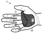
図1(a)において、インターフェース装置1は、操作者の一方の手の平(ここでは、右手の手の平)の少なくとも一部に接触する部材10を備えている。該部材10の操作者の手の平に対向する面とは反対側の面上には、広角レンズ21及びライト22を備えるカメラモジュール20が配置されている。 In FIG. 1A, the
また、部材10の内部には、加速度センサ33及びジャイロセンサ34が搭載されている。加速度センサ33及びジャイロセンサ34により、例えば、操作者の手首の回転や、手の上下左右への振れ等を検出することができる。尚、図1(a)では、説明の便宜上、加速度センサ33及びジャイロセンサ34を、部材10上に記載している。 An
本実施形態では特に、図1(a)に示すように、操作者がインターフェース装置1を装着した際に、カメラモジュール20の位置が操作者の手の掌底部に該当するように、該カメラモジュール20が配置されている。 Particularly in the present embodiment, as shown in FIG. 1A, when the operator wears the
このように構成することにより、カメラモジュール20のレンズ21から操作者の指までの距離を比較的長くすることができる。すると、レンズ21の視野角が比較的小さい場合であっても、操作者の一方の手の指を好適に撮像することができる。 With this configuration, the distance from the
具体的には例えば図3に示すように、操作者の一方の手の指を、指の付け根から撮像することができるので、撮像された画像を解析する際に、インターフェース装置1が指を誤認識する可能性を抑制することができる。図3は、本実施形態に係るインターフェース装置が備えるカメラにより撮像された画像の一例である。 Specifically, for example, as shown in FIG. 3, since the finger of one hand of the operator can be imaged from the base of the finger, the
加えて、例えば操作者の指がカメラモジュール20のレンズ21に触れることによって、レンズ21に汚れが付着することを抑制することができる。 In addition, for example, when the operator's finger touches the
また、カメラモジュール20は、本発明に係る「発光部」の一例としての、ライト22を備えている。このため、周囲が比較的暗い場合であっても、操作者の指をカメラモジュール20により好適に撮像することができる。従って、インターフェース装置1を、例えばカーナビゲーション装置のリモートコントローラとして用いた場合に、夜間の車内においても、好適にカーナビゲーション装置を操作することができる。 The
歪センサ31は、操作者の各指の付け根部に接触するパッドと、該パッドとインターフェース装置1本体とを接続するバネ状構造とを備えて構成されている。歪センサ31は、歪抵抗効果や圧電性を利用して、操作者の指の付け根部の変位を示す信号を出力する。尚、歪センサ31は、比較的柔らかい樹脂フィルム等で覆われていることが好ましい。 The
電極バッド32は、操作者の指の付け根部に接触するように、インターフェース装置1本体に接続されている。電極パッド32の操作者の指の付け根部に接触する面には、操作者の手の筋電位を測定する電極部(図示せず)が設けられている。 The
図1(b)において、インターフェース装置1の、操作者の手の甲側の部材には、制御回路11、無線通信モジュール13、バッテリ14及びスピーカ15が内蔵さえており、ディスプレイ12がカバーとして、手の甲側の部材の表面の一部を覆っている。 In FIG. 1B, the
図2に示すように、制御回路11、ディスプレイ12、無線通信モジュール13、バッテリ14、スピーカ15、押ボタン16、カメラモジュール20、歪センサ31、電極パッド32、加速センサ33及びジャイロセンサ34は、相互に電気的に接続されている。 As shown in FIG. 2, the
制御回路11は、カメラモジュール20により撮像された画像に対して画像解析処理を施して、撮像された画像から操作者の指を抽出すると共に、指の形状を判別する。制御回路11は、更に、複数枚の連続して撮像された画像から、操作者の指の動き(例えば、軌跡、速度等)を検出する。 The
制御回路11は、歪センサ31から出力される、操作者の指の付け根部の動きを示す信号に基づいて、例えば、操作者の指が何らかの対象物に接触したか否かを判定する。また、制御回路11は、電極パッド32から出力される、筋電位を示す信号、電極パッド32の電極と周辺部材との間に生じる静電容量(即ち、浮遊容量)を示す信号、及び電極間の抵抗値を示す信号に基づいて、例えば、操作者の指が何らかの対象物に接触したか否かを判定する。 The
このように構成すれば、撮像された画像から得られた操作者の指が動いていない場合であっても、歪センサ31及び電極パッド32各々から出力される信号に基づいて、操作者の指が何らかの対象物に接触していることを検出することができる。 According to this configuration, even when the operator's finger obtained from the captured image is not moving, the operator's finger is based on the signals output from the
尚、制御回路11は、歪センサ31から出力される信号、及び電極パッド32から出力される信号のうち一方の信号のみに基づいて、操作者の指が何らかの対象物に接触したか否かを判定してよい。 Note that the
制御回路11は、撮像された画像に基づく操作者の指の形状及び動作と、歪センサ31、電極パッド32、加速度センサ33及びジャイロセンサ34各々から出力された信号と、に基づいて、操作者の手の動作(例えば、ジェスチャ)を検出する。 Based on the shape and movement of the operator's finger based on the captured image and the signals output from the
制御回路11は、予め格納されているデータベースから、検出された手の動作に対応するコマンドを特定する。続いて、制御回路11は、(i)該特定されたコマンドを示す信号を無線通信モジュール13を介して、インターフェース装置1が対象とする電子機器等に送信する、(ii)該特定されたコマンドに対応する情報をディスプレイ12に表示する、及び(iii)該特定されたコマンドに対応する音声をスピーカ15から出力する、の少なくとも一つを実行する。 The
尚、インターフェース装置1は、電極パッド32に代えて、例えば加速度センサ又は圧電体からなる片持ち梁構造等の振動センサを備えていてもよい。 Note that the
本実施形態に係る「制御回路11」は、本発明に係る「検出手段」の一例である。本実施形態に係る「歪センサ31」、「電極パッド32」、「加速度センサ33」及び「ジャイロセンサ34」は、本発明に係る「慣性センサ」の一例である。 The “
<変形例>
本実施形態に係るインターフェース装置の変形例について、図4を参照して説明する。図4は、図1(a)と同趣旨の、本実施形態の変形例に係るインターフェース装置の具体的な構成を示す図である。尚、図4では、図1(a)に示した部材を適宜省略して示している。<Modification>
A modification of the interface device according to the present embodiment will be described with reference to FIG. FIG. 4 is a diagram showing a specific configuration of an interface device according to a modification of the present embodiment having the same meaning as in FIG. In FIG. 4, the members shown in FIG. 1A are omitted as appropriate.
図4に示すように、インターフェース装置2が備える歪センサ31は、そのパッドが、操作者の指の中手指節間間接と近位指節間間接との間に接触するように構成されている。 As shown in FIG. 4, the
以下、本実施形態に係るインターフェース装置の実施例について説明する。 Hereinafter, examples of the interface device according to the present embodiment will be described.
<第1実施例>
インターフェース装置1を、例えばターンテーブル、ミキサー等の音響機器のコントローラとして使用する場合、例えば、演奏されている楽曲に対するエフェクトの変更、演奏されている楽曲の再生位置の変更、楽曲の選択等が、操作者の手の動作に対応するコマンドとしてデータベースに格納されている。<First embodiment>
When the
このように構成すれば、例えばDJ(Disc Jockey)が、音響機器(この場合は、DJ機器)から比較的離れた位置で、スクラッチするようなジェスチャをすることにより、スクラッチ音を発生させることができる。この結果、DJが大げさなジェスチャでオーディエンスにアピールしながら、DJプレイを行うことができる。 With this configuration, for example, a DJ (Disc Jockey) can generate a scratch sound by making a gesture of scratching at a position relatively distant from the acoustic device (in this case, the DJ device). it can. As a result, DJ play can be performed while appealing to the audience with exaggerated gestures.
尚、インターフェース装置1を、DJ機器のコントローラとして使用する場合、該DJ機器が設置される施設内の照明のコントローラとして使用されてもよい。このように構成すれば、DJが、DJ機器と照明とのコントロールをインターフェース装置1のみにより行うことができるので、実用上非常に有利である。 In addition, when using the
<第2実施例>
インターフェース装置1を、コミュニケーション支援装置として使用する場合、例えば文字コードが、操作者の手の動作に対応するコマンドとしてデータベースに格納されている。具体的には例えば、図5(a)に示すように、操作者が親指と人差し指又は中指とを接触させるという動作のパターン毎に、図5(b)に示すような文字が割り当てられる。図5は、操作者の手の動作に起因してインターフェース装置が検出する信号と、文字と、の対応関係の一例を示す表である。<Second embodiment>
When the
例えば、親指と人差し指とが一瞬接触した際の信号を「・」とし、親指と人差し指とが0.5秒程度接触した際の信号を「−」とする。そして、操作者が手首を回転させた際に、一文字の入力が終了するものとする。 For example, a signal when the thumb and the index finger are in contact for a moment is “·”, and a signal when the thumb and the index finger are in contact for about 0.5 seconds is “−”. Then, when the operator rotates the wrist, the input of one character is completed.
この場合、操作者が、親指と人差し指とを一瞬接触した後に、親指と人差し指とを0.5秒程度接触し、その後手首を回転すると、インターフェース装置1の制御回路11は、入力された信号を「・−」と認識する。続いて、制御回路11は、文字「A」を示す信号を、例えば無線通信モジュール13を介して、外部のモニタに送信する。この結果、外部のモニタに「A」という文字が表示される。 In this case, when the operator touches the thumb and forefinger for a moment, then touches the thumb and forefinger for about 0.5 seconds, and then rotates the wrist, the
このように構成すれば、操作者が、例えば親指と人差し指との接触を時系列的に繰り返すことにより、他者とコミュニケーションを図ることができる。この結果、例えば、病気や作業環境により会話が困難な人が、自分の意思を適切に他者に伝えることができる。 If comprised in this way, an operator can aim at communication with others by repeating contact with a thumb and an index finger in time series, for example. As a result, for example, a person whose conversation is difficult due to illness or working environment can appropriately convey his intention to others.
<第3実施例>
インターフェース装置1を、コンピュータのインターフェースとして使用する場合、例えば、コンピュータの画面上に表示されるカーソルの移動、アイコンやテキストボックスの選択、文字コード等が、操作者の手の動作に対応するコマンドとしてデータベースに格納されている。<Third embodiment>
When the
インターフェース装置1は、図1に示すように、操作者の指先には何らの部材も接触していない。このため、操作者がインターフェース装置1を装着したまま、例えばペンやカップ等を、ほとんど支障なく、使用したり持ったりすることができる。 As shown in FIG. 1, the
特に、ユーザの体に装着するコンピュータ(所謂、ウェアラブルコンピュータ)やユーザの頭部に装着するディスプレイ(所謂、ウェアラブルディスプレイ)のインターフェースとして、インターフェース装置1を使用すれば、ユーザが例えばマウスやキーボード等を持ち歩く必要がなくなるので、ユーザの利便性を向上させることができる。 In particular, when the
<第4実施例>
インターフェース装置1を、例えば産業用ロボット等のロボットのコントローラとして使用する場合、対象とするロボットの動作に対応するコマンドが、操作者の手の動作に対応するコマンドとしてデータベースに格納されている。<Fourth embodiment>
When the
このように構成すれば、危険な空間(例えば、災害現場等)や遠隔地等で作業させるロボットを、操作者が適切に制御することができる。 If comprised in this way, the operator can control appropriately the robot operated in dangerous space (for example, disaster spot etc.) or a remote place.
ところで、操作者の手の複数の部位に慣性運動センサを装着して、例えばロボットアームを制御するコントローラは既に存在する。しかしながら、インターフェース装置1では、カメラモジュール20により撮像された画像も利用しているので、より精度良く操作者の手の動作を検出することができる。 By the way, a controller that controls the robot arm by attaching inertial motion sensors to a plurality of parts of the operator's hand already exists. However, since the
<第5実施例>
インターフェース装置1を、例えば照明器具、テレビ、オーディオ機器、ゲーム機等の家電のコントローラとして使用する場合、例えば機器のON/OFF、音量の変更、選局、明るさの変更等が、操作者の手の動作に対応するコマンドとしてデータベースに格納されている。<Fifth embodiment>
When the
このように構成すれば、家電のリモートコントローラの小型化を図ることができる。更に、インターフェース装置1により複数の家電を制御可能なように構成すれば、例えばリモートコントローラの持ち替え動作を無くすことができ、ユーザの利便性を向上させることができる。 If comprised in this way, size reduction of the remote controller of household appliances can be achieved. Further, if the
特に、3次元映像のゲーム機のコントローラとして、インターフェース装置1を使用すれば、例えばユーザが表示された物体を押す等の動作を、反映させることができる。 In particular, if the
本発明は、上述した実施形態に限られるものではなく、特許請求の範囲及び明細書全体から読み取れる発明の要旨或いは思想に反しない範囲で適宜変更可能であり、そのような変更を伴うインターフェース装置もまた本発明の技術的範囲に含まれるものである。 The present invention is not limited to the above-described embodiment, and can be appropriately changed without departing from the gist or concept of the invention that can be read from the claims and the entire specification, and an interface device with such a change is also possible. Moreover, it is included in the technical scope of the present invention.
1、2…インターフェース装置、11…制御回路、12…ディスプレイ、13…無線通信モジュール、14…バッテリ、15…スピーカ、20…カメラモジュール、21…広角レンズ、22…ライト、31…歪センサ、32…電極パッド、33…加速度センサ、34…ジャイロセンサ DESCRIPTION OF
Claims (8)
Translated fromJapanese当該インターフェース装置の装着時に、前記操作者の一方の手の平の少なくとも一部に接触する部材と、
前記部材の前記一方の手の平に対向する面とは反対側の面上に配置されたカメラと、
前記カメラにより撮像された画像に基づいて、前記一方の手の動作を検出する検出手段と
を備えることを特徴とするインターフェース装置。An interface device that is attached to an operator's hand,
A member that contacts at least a part of one palm of the operator when the interface device is mounted;
A camera disposed on a surface of the member opposite to the surface facing the one palm;
An interface device comprising: detecting means for detecting an operation of the one hand based on an image picked up by the camera.
前記検出手段は、前記撮像された画像及び前記検出された慣性に基づいて、前記一方の手の動作を検出する
ことを特徴とする請求項1に記載のインターフェース装置。An inertial sensor for detecting inertia generated in the one hand;
The interface device according to claim 1, wherein the detection unit detects the movement of the one hand based on the captured image and the detected inertia.
Priority Applications (1)
| Application Number | Priority Date | Filing Date | Title |
|---|---|---|---|
| JP2010218261AJP2012073830A (en) | 2010-09-29 | 2010-09-29 | Interface device |
Applications Claiming Priority (1)
| Application Number | Priority Date | Filing Date | Title |
|---|---|---|---|
| JP2010218261AJP2012073830A (en) | 2010-09-29 | 2010-09-29 | Interface device |
Publications (1)
| Publication Number | Publication Date |
|---|---|
| JP2012073830Atrue JP2012073830A (en) | 2012-04-12 |
Family
ID=46169927
Family Applications (1)
| Application Number | Title | Priority Date | Filing Date |
|---|---|---|---|
| JP2010218261APendingJP2012073830A (en) | 2010-09-29 | 2010-09-29 | Interface device |
Country Status (1)
| Country | Link |
|---|---|
| JP (1) | JP2012073830A (en) |
Cited By (22)
| Publication number | Priority date | Publication date | Assignee | Title |
|---|---|---|---|---|
| JP2014102840A (en)* | 2012-11-20 | 2014-06-05 | Samsung Electronics Co Ltd | User gesture input to wearable electronic device involving movement of device |
| CN104238736A (en)* | 2013-06-17 | 2014-12-24 | 三星电子株式会社 | Device, method, and system to recognize motion using gripped object |
| KR20160068447A (en)* | 2014-12-05 | 2016-06-15 | 삼성전자주식회사 | Method for determining region of interest of image and device for determining region of interest of image |
| WO2016121034A1 (en)* | 2015-01-28 | 2016-08-04 | 株式会社ウェアラブルデバイス総合研究所 | Wearable device, input method, and program |
| JP2016170581A (en)* | 2015-03-12 | 2016-09-23 | 株式会社ニコン | Input device, input method, and computer program |
| JP2017004458A (en)* | 2015-06-16 | 2017-01-05 | 富士通株式会社 | INPUT DEVICE, INPUT CONTROL METHOD, AND INPUT CONTROL PROGRAM |
| CN106452486A (en)* | 2016-08-31 | 2017-02-22 | 杭州鸿雁电器有限公司 | Control method and system based on wireless broadcasting signal communication |
| JPWO2016038953A1 (en)* | 2014-09-10 | 2017-06-22 | ソニー株式会社 | DETECTING DEVICE, DETECTING METHOD, CONTROL DEVICE, AND CONTROL METHOD |
| JP2018505500A (en)* | 2015-01-19 | 2018-02-22 | カーブ・ミュージック・リミテッド | Handheld controller for computer, control system for computer and computer system |
| KR101937686B1 (en) | 2017-10-27 | 2019-01-14 | 박재홍 | Wearable control device |
| US10185416B2 (en) | 2012-11-20 | 2019-01-22 | Samsung Electronics Co., Ltd. | User gesture input to wearable electronic device involving movement of device |
| US10194060B2 (en) | 2012-11-20 | 2019-01-29 | Samsung Electronics Company, Ltd. | Wearable electronic device |
| US10423214B2 (en) | 2012-11-20 | 2019-09-24 | Samsung Electronics Company, Ltd | Delegating processing from wearable electronic device |
| KR20200002413A (en)* | 2018-06-29 | 2020-01-08 | 조선대학교산학협력단 | Band-type optical wireless mouse |
| US10551928B2 (en) | 2012-11-20 | 2020-02-04 | Samsung Electronics Company, Ltd. | GUI transitions on wearable electronic device |
| US10691332B2 (en) | 2014-02-28 | 2020-06-23 | Samsung Electronics Company, Ltd. | Text input on an interactive display |
| US10884498B2 (en) | 2018-10-30 | 2021-01-05 | Seiko Epson Corporation | Display device and method for controlling display device |
| WO2021182176A1 (en)* | 2020-03-13 | 2021-09-16 | ソニーグループ株式会社 | Information processing device, information processing method, and information processing program |
| US11157436B2 (en) | 2012-11-20 | 2021-10-26 | Samsung Electronics Company, Ltd. | Services associated with wearable electronic device |
| JPWO2022014445A1 (en)* | 2020-07-14 | 2022-01-20 | ||
| US11237719B2 (en) | 2012-11-20 | 2022-02-01 | Samsung Electronics Company, Ltd. | Controlling remote electronic device with wearable electronic device |
| US11372536B2 (en) | 2012-11-20 | 2022-06-28 | Samsung Electronics Company, Ltd. | Transition and interaction model for wearable electronic device |
- 2010
- 2010-09-29JPJP2010218261Apatent/JP2012073830A/enactivePending
Cited By (37)
| Publication number | Priority date | Publication date | Assignee | Title |
|---|---|---|---|---|
| JP2014102840A (en)* | 2012-11-20 | 2014-06-05 | Samsung Electronics Co Ltd | User gesture input to wearable electronic device involving movement of device |
| US11157436B2 (en) | 2012-11-20 | 2021-10-26 | Samsung Electronics Company, Ltd. | Services associated with wearable electronic device |
| US10551928B2 (en) | 2012-11-20 | 2020-02-04 | Samsung Electronics Company, Ltd. | GUI transitions on wearable electronic device |
| US11237719B2 (en) | 2012-11-20 | 2022-02-01 | Samsung Electronics Company, Ltd. | Controlling remote electronic device with wearable electronic device |
| US10423214B2 (en) | 2012-11-20 | 2019-09-24 | Samsung Electronics Company, Ltd | Delegating processing from wearable electronic device |
| US10194060B2 (en) | 2012-11-20 | 2019-01-29 | Samsung Electronics Company, Ltd. | Wearable electronic device |
| US10185416B2 (en) | 2012-11-20 | 2019-01-22 | Samsung Electronics Co., Ltd. | User gesture input to wearable electronic device involving movement of device |
| US9477313B2 (en) | 2012-11-20 | 2016-10-25 | Samsung Electronics Co., Ltd. | User gesture input to wearable electronic device involving outward-facing sensor of device |
| US11372536B2 (en) | 2012-11-20 | 2022-06-28 | Samsung Electronics Company, Ltd. | Transition and interaction model for wearable electronic device |
| US10019078B2 (en) | 2013-06-17 | 2018-07-10 | Samsung Electronics Co., Ltd. | Device, method, and system to recognize motion using gripped object |
| CN104238736B (en)* | 2013-06-17 | 2019-02-15 | 三星电子株式会社 | Apparatus, method and system for motion recognition using grasped objects |
| CN104238736A (en)* | 2013-06-17 | 2014-12-24 | 三星电子株式会社 | Device, method, and system to recognize motion using gripped object |
| KR102170321B1 (en)* | 2013-06-17 | 2020-10-26 | 삼성전자주식회사 | System, method and device to recognize motion using gripped object |
| US10649549B2 (en) | 2013-06-17 | 2020-05-12 | Samsung Electronics Co., Ltd. | Device, method, and system to recognize motion using gripped object |
| KR20140146346A (en)* | 2013-06-17 | 2014-12-26 | 삼성전자주식회사 | System, method and device to recognize motion using gripped object |
| JP2015001978A (en)* | 2013-06-17 | 2015-01-05 | 三星電子株式会社Samsung Electronics Co.,Ltd. | Method of recognizing motion using gripped object, and device and system therefor |
| US10691332B2 (en) | 2014-02-28 | 2020-06-23 | Samsung Electronics Company, Ltd. | Text input on an interactive display |
| US10635171B2 (en) | 2014-09-10 | 2020-04-28 | Sony Corporation | Detection device, detection method, control device, and control method |
| JPWO2016038953A1 (en)* | 2014-09-10 | 2017-06-22 | ソニー株式会社 | DETECTING DEVICE, DETECTING METHOD, CONTROL DEVICE, AND CONTROL METHOD |
| US11157080B2 (en) | 2014-09-10 | 2021-10-26 | Sony Corporation | Detection device, detection method, control device, and control method |
| KR20160068447A (en)* | 2014-12-05 | 2016-06-15 | 삼성전자주식회사 | Method for determining region of interest of image and device for determining region of interest of image |
| KR102356599B1 (en) | 2014-12-05 | 2022-01-28 | 삼성전자주식회사 | Method for determining region of interest of image and device for determining region of interest of image |
| JP2018505500A (en)* | 2015-01-19 | 2018-02-22 | カーブ・ミュージック・リミテッド | Handheld controller for computer, control system for computer and computer system |
| WO2016121034A1 (en)* | 2015-01-28 | 2016-08-04 | 株式会社ウェアラブルデバイス総合研究所 | Wearable device, input method, and program |
| JP2016170581A (en)* | 2015-03-12 | 2016-09-23 | 株式会社ニコン | Input device, input method, and computer program |
| JP2017004458A (en)* | 2015-06-16 | 2017-01-05 | 富士通株式会社 | INPUT DEVICE, INPUT CONTROL METHOD, AND INPUT CONTROL PROGRAM |
| CN106452486A (en)* | 2016-08-31 | 2017-02-22 | 杭州鸿雁电器有限公司 | Control method and system based on wireless broadcasting signal communication |
| KR101937686B1 (en) | 2017-10-27 | 2019-01-14 | 박재홍 | Wearable control device |
| KR102127465B1 (en)* | 2018-06-29 | 2020-06-29 | 조선대학교산학협력단 | Band-type optical wireless mouse |
| KR20200002413A (en)* | 2018-06-29 | 2020-01-08 | 조선대학교산학협력단 | Band-type optical wireless mouse |
| US10884498B2 (en) | 2018-10-30 | 2021-01-05 | Seiko Epson Corporation | Display device and method for controlling display device |
| WO2021182176A1 (en)* | 2020-03-13 | 2021-09-16 | ソニーグループ株式会社 | Information processing device, information processing method, and information processing program |
| US11977681B2 (en) | 2020-03-13 | 2024-05-07 | Sony Group Corporation | Information processing device and information processing method |
| JPWO2022014445A1 (en)* | 2020-07-14 | 2022-01-20 | ||
| WO2022014445A1 (en)* | 2020-07-14 | 2022-01-20 | ソニーグループ株式会社 | Detecting device, and detecting method |
| US12045388B2 (en) | 2020-07-14 | 2024-07-23 | Sony Group Corporation | Finger detection device and method providing increased reliability detecting attitudes of fingers |
| JP7667961B2 (en) | 2020-07-14 | 2025-04-24 | ソニーグループ株式会社 | Detection device and detection method |
Similar Documents
| Publication | Publication Date | Title |
|---|---|---|
| JP2012073830A (en) | Interface device | |
| CN210573659U (en) | Computer system, head-mounted device, finger device, and electronic device | |
| CN103970265B (en) | Augmented reality user interface with haptic feedback | |
| JP6669069B2 (en) | Detection device, detection method, control device, and control method | |
| TWI390430B (en) | Device for multiple inputs | |
| EP3057297B1 (en) | Accessory and information processing system | |
| KR101313106B1 (en) | Thimble-type mediated device and method for recognizing thimble gesture using the device | |
| US20100328267A1 (en) | Optical touch device | |
| CN102314232B (en) | A multifunctional mouse | |
| US20150378447A1 (en) | Terminal device, control method for terminal device, and program | |
| JP2013125247A (en) | Head-mounted display and information display apparatus | |
| WO2007024163A1 (en) | Free-space pointing and handwriting | |
| US10261327B2 (en) | Head mounted display and control method for head mounted display | |
| US20070191112A1 (en) | Storage medium storing subject selecting program and subject selecting apparatus | |
| WO2020110547A1 (en) | Information processing device, information processing method, and program | |
| US20230095328A1 (en) | Information processing apparatus, information processing method, computer program, and augmented reality system | |
| US20190384419A1 (en) | Handheld controller, tracking method and system using the same | |
| JPWO2018003862A1 (en) | CONTROL DEVICE, DISPLAY DEVICE, PROGRAM, AND DETECTION METHOD | |
| CN103744542A (en) | Hybrid pointing device | |
| KR20150145729A (en) | Method for moving screen and selecting service through fingerprint input, wearable electronic device with fingerprint sensor and computer program | |
| US20110095983A1 (en) | Optical input device and image system | |
| CN202275375U (en) | Wireless mouse | |
| JP7667961B2 (en) | Detection device and detection method | |
| KR100749033B1 (en) | How to operate the terminal by tracking the light reflected from both eyes, and the device | |
| CN201926995U (en) | Remote input device |