JP2012070961A - Inter-stand display device - Google Patents
Inter-stand display deviceDownload PDFInfo
- Publication number
- JP2012070961A JP2012070961AJP2010218289AJP2010218289AJP2012070961AJP 2012070961 AJP2012070961 AJP 2012070961AJP 2010218289 AJP2010218289 AJP 2010218289AJP 2010218289 AJP2010218289 AJP 2010218289AJP 2012070961 AJP2012070961 AJP 2012070961A
- Authority
- JP
- Japan
- Prior art keywords
- image display
- display means
- inter
- unit
- display screen
- Prior art date
- Legal status (The legal status is an assumption and is not a legal conclusion. Google has not performed a legal analysis and makes no representation as to the accuracy of the status listed.)
- Granted
Links
- 230000000414obstructive effectEffects0.000abstract1
- 239000004973liquid crystal related substanceSubstances0.000description33
- 230000007246mechanismEffects0.000description22
- 230000004308accommodationEffects0.000description2
- 238000004519manufacturing processMethods0.000description2
- 238000012423maintenanceMethods0.000description1
- 230000010355oscillationEffects0.000description1
Images


Landscapes
- Pinball Game Machines (AREA)
Abstract
Description
Translated fromJapanese本発明は、島設備の隣接する遊技機間に設置される装置本体と、該装置本体に配設されるとともに、所定の画像表示を行い得る表示画面を有した画像表示手段とを具備した台間表示装置に関するものである。 The present invention provides a device main body installed between adjacent gaming machines of an island facility, and an image display means disposed on the device main body and having a display screen capable of performing a predetermined image display. The present invention relates to an intermediate display device.
遊技場における島設備には、パチンコ遊技機等の遊技機が複数設置されるとともに、隣接する遊技機の間には台間表示装置が設置されているものがある。従来の台間表示装置は、島設備の隣接する遊技機間に設置される筐体としての装置本体と、該装置本体に突出状態で配設されるとともに所定の画像表示を行い得る表示画面(液晶画面等)を有した画像表示手段(液晶ユニット)とを備えており、当該表示画面に種々情報を把握し得る画像(例えば遊技機や遊技場に関する情報或いはテレビ画像等)を表示して、遊技機前に着座した遊技者が視認し得るようになっていた。尚、かかる先行技術は、文献公知発明に係るものでないため、記載すべき先行技術文献情報はない。 Some island facilities in amusement halls are equipped with a plurality of gaming machines such as pachinko gaming machines, and a table display device is installed between adjacent gaming machines. A conventional inter-table display device includes a device main body as a casing installed between adjacent gaming machines of an island facility, and a display screen that is arranged in a protruding state on the device main body and can perform predetermined image display ( An image display means (liquid crystal unit) having a liquid crystal screen, etc., and displaying an image (for example, information on a gaming machine or a game room or a television image) that can grasp various information on the display screen, A player seated in front of a gaming machine can be visually recognized. In addition, since this prior art does not relate to the literature known invention, there is no prior art document information to be described.
しかしながら、上記従来の台間表示装置においては、画像表示手段が装置本体に突出状態で配設されていたため、遊技中に画像表示手段の表示画面を見ないとき(遊技者が表示画面を見る必要がないとき及び見たくないときの両者含む)等、当該画像表示手段が邪魔になってしまう虞があった。また、遊技機に対して所定の作業を行う際(例えばパチンコ遊技機の前枠を開放して内部のメンテナンスなどを行う際)、画像表示手段が邪魔となって作業性が悪化してしまう虞もあった。 However, in the conventional inter-table display device, since the image display means is provided in a protruding state on the apparatus body, when the display screen of the image display means is not seen during the game (the player needs to see the display screen) The image display means may be in the way, such as when there is no image and when you do not want to see). In addition, when a predetermined operation is performed on the gaming machine (for example, when the front frame of the pachinko gaming machine is opened to perform internal maintenance, etc.), the workability may be deteriorated due to the image display means being in the way. There was also.
本発明は、このような事情に鑑みてなされたもので、画像表示手段が邪魔になってしまうのを回避することができる台間表示装置を提供することにある。 The present invention has been made in view of such circumstances, and it is an object of the present invention to provide a table display device capable of avoiding that the image display means is in the way.
請求項1記載の発明は、島設備の隣接する遊技機間に設置される装置本体と、該装置本体に配設されるとともに、所定の画像表示を行い得る表示画面を有した画像表示手段とを具備した台間表示装置において、前記画像表示手段は、装置本体の内部に収容された収容位置と、当該装置本体から突出して表示画面を視認させ得る突出位置との間で移動可能とされたことを特徴とする。 The invention according to
請求項2記載の発明は、請求項1記載の台間表示装置において、前記装置本体に操作手段を有するとともに、当該操作手段を操作することによって前記画像表示手段を前記収容位置から突出位置まで自動的に移動させることを特徴とする。 According to a second aspect of the present invention, in the inter-table display device according to the first aspect, the apparatus main body has an operation means, and the image display means is automatically moved from the housed position to the protruding position by operating the operation means. It is characterized by making it move.
請求項3記載の発明は、請求項2記載の台間表示装置において、前記画像表示手段を前記収容位置から突出位置に向かって付勢する付勢手段を具備し、前記操作手段は、当該画像表示手段を前記収容位置で係止可能とされるとともに、当該操作手段を操作することにより当該係止を解除し、前記付勢手段の付勢力にて当該画像表示手段を前記収容位置から突出位置まで自動的に移動させることを特徴とする。 According to a third aspect of the present invention, in the inter-table display device according to the second aspect, the image display unit includes a biasing unit that biases the image display unit from the storage position toward the protruding position, and the operation unit includes the image display unit. The display means can be locked at the storage position, and the lock is released by operating the operation means, and the image display means is projected from the storage position by the biasing force of the biasing means. It is characterized by automatically moving to.
請求項4記載の発明は、請求項1〜3の何れか1つに記載の台間表示装置において、前記画像表示手段は、前記突出位置で前記表示画面の向きが任意調整可能とされたことを特徴とする。 According to a fourth aspect of the present invention, in the inter-table display device according to any one of the first to third aspects, the image display means can arbitrarily adjust the orientation of the display screen at the protruding position. It is characterized by.
請求項5記載の発明は、請求項1〜3の何れか1つに記載の台間表示装置において、前記画像表示手段は、前記収容位置から突出位置に至ると前記表示画面が自動的に所定の向きとされることを特徴とする。 According to a fifth aspect of the present invention, in the inter-table display device according to any one of the first to third aspects, when the image display means reaches the protruding position from the storage position, the display screen is automatically determined in advance. It is characterized by the direction.
請求項1の発明によれば、画像表示手段が、装置本体の内部に収容された収容位置と、当該装置本体から突出して表示画面を視認させ得る突出位置との間で移動可能とされ、表示画面を見るときに限り画像表示手段を突出位置として表示画面を視認させ得るとともに、当該表示画面を見ないときには画像表示手段を収容位置とすることができるので、画像表示手段が邪魔になってしまうのを回避することができる。 According to the first aspect of the present invention, the image display means is movable between a housing position housed inside the apparatus main body and a projecting position that projects from the apparatus main body and allows the display screen to be visually recognized. Only when viewing the screen, the image display means can be viewed as a protruding position, and when the display screen is not viewed, the image display means can be set as the storage position, so the image display means becomes an obstacle. Can be avoided.
請求項2の発明によれば、装置本体に操作手段を有するとともに、当該操作手段を操作することによって画像表示手段を収容位置から突出位置まで自動的に移動させるので、画像表示手段の操作性を向上させることができる。 According to the invention of
請求項3の発明によれば、画像表示手段を前記収容位置から突出位置に向かって付勢する付勢手段を具備し、操作手段は、当該画像表示手段を収容位置で係止可能とされるとともに、当該操作手段を操作することにより当該係止を解除し、付勢手段の付勢力にて当該画像表示手段を収容位置から突出位置まで自動的に移動させるので、モータなどの別個のアクチュエータを必要とせず、製造コストを低減させることができる。 According to a third aspect of the present invention, there is provided a biasing means for biasing the image display means from the storage position toward the protruding position, and the operation means can lock the image display means at the storage position. At the same time, the operation means is operated to release the locking, and the urging force of the urging means automatically moves the image display means from the housed position to the protruding position. This is not necessary and the manufacturing cost can be reduced.
請求項4の発明によれば、画像表示手段は、突出位置で表示画面の向きが任意調整可能とされたので、遊技者が任意に画像表示手段の表示画面の向きを変えることができ、当該表示画面の視認性を向上させることができる。 According to the invention of
請求項5の発明によれば、画像表示手段は、収容位置から突出位置に至ると表示画面が自動的に所定の向きとされるので、画像表示手段の操作性をより一層向上させることができる。 According to the invention of
以下、本発明の実施形態について図面を参照しながら具体的に説明する。
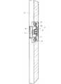
第1の実施形態に係る台間表示装置は、図21及び図22に示すように、遊技場内の島設備Sの隣接するパチンコ遊技機P間に設置されたもので、図1〜10に示すように、装置本体2と、該装置本体2に配設されるとともに、所定の画像表示を行い得る表示画面3aを有した画像表示手段3と、操作手段4と、移動機構5とから主に構成されている。Hereinafter, embodiments of the present invention will be specifically described with reference to the drawings.
As shown in FIGS. 21 and 22, the inter-table display device according to the first embodiment is installed between adjacent pachinko gaming machines P of the island facility S in the game hall, and is shown in FIGS. 1 to 10. As described above, the apparatus
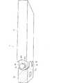
装置本体2は、島設備Sにおける隣接するパチンコ遊技機P間に設置されて本実施形態に係る台間表示装置1の筐体を成し、その内部に画像表示手段3、操作手段4及び移動機構5がそれぞれ組み付けられたものである。かかる装置本体2は、図22に示すように、隣接するパチンコ遊技機Pと略等しい高さで、且つ、所定の幅寸法(画像表示手段3及び移動機構5を内在し得る寸法)を有した箱状部材から成る。 The apparatus
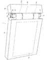
画像表示手段3は、装置本体2に配設されるとともに、所定の画像表示(例えばパチンコ遊技機Pや遊技場に関する情報或いはテレビ画像等の表示)を行い得る表示画面3a(本実施形態においては液晶表示画面)を有したものである。かかる画像表示手段3は、移動機構5によって、装置本体2の内部に収容された収容位置(図2参照)と、当該装置本体2から正面側に突出して表示画面3aを視認させ得る突出位置(図3参照)との間で移動可能とされているとともに、突出位置で表示画面3aの向きが任意調整可能(図4参照)とされている。 The image display means 3 is disposed in the apparatus
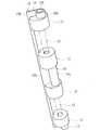
移動機構5は、図5に示すように、装置本体2の所定位置に配設されたもので、画像表示手段3を収容位置から突出位置に自動的に移動させるためのものである。かかる移動機構5は、図6、7に示すように、画像表示手段3の移動方向に延びる一対の溝6aが形成された案内部材6と、該案内部材6の一対の溝6aに嵌合しつつ当該溝6aに沿って摺動可能とされるとともに画像表示手段3の固定側ユニット3bが固定される摺動部材7と、ベルトVと、上下一対の付勢手段8とから主に構成されている。 As shown in FIG. 5, the
ベルトVは、両端がそれぞれ付勢手段8と連結されるとともに、途中の部位に摺動部材7が引掛けられており、付勢手段8の付勢力(具体的には、渦巻きバネ8aによる付勢力)が常時摺動部材7に付与されるようになっている。即ち、付勢手段8の付勢力がベルトVを介して摺動部材7に伝わり、当該摺動部材7を図6、7で示す位置から図8で示す位置に向かって常時付勢していることから、かかる摺動部材7と連結された画像表示手段3が収容位置から突出位置に向かって付勢されているのである。尚、図中符号T1〜T3は、ベルトVを懸架して案内する案内ローラを示している。 Both ends of the belt V are connected to the
操作手段4は、図9、10で示すように、画像表示手段3を収容位置で係止可能とされるとともに、当該操作手段4を操作することにより当該係止を解除し、付勢手段8の付勢力にて当該画像表示手段3を収容位置から突出位置まで自動的に移動させるためのものである。即ち、操作手段4は、装置本体2の表面側に突出した操作部4aと、画像表示手段3と係止し得る係止部4bと、操作手段4全体を常時上方に向かって付勢するコイルスプリング4cとから主に構成されている。 As shown in FIGS. 9 and 10, the operation means 4 can lock the image display means 3 at the storage position, and releases the lock by operating the operation means 4, and the biasing means 8. The image display means 3 is automatically moved from the storage position to the protruding position by the urging force. That is, the
そして、操作部4aを下方に押圧操作してコイルスプリング4cの付勢力に抗して操作手段4を下降させると、収容位置にある画像表示手段3と係止した係止部4bが下方に下がり、係止が解かれることから、当該画像表示手段3が付勢手段8による付勢力で突出位置まで自動的に(自然と)移動するよう構成されているのである。而して、操作手段4を操作することによって画像表示手段3を収容位置から突出位置まで自動的に移動させることができる。 Then, when the
ここで、本実施形態に係る画像表示手段3は、図2及び図11〜16に示すように、固定側ユニット3bと、液晶ユニット3cと、軸部材3fとから主に構成されており、当該軸部材3fを介して固定側ユニット3bに対して液晶ユニット3cが揺動自在に組み付けられて構成されている。而して、固定側ユニット3bに対して液晶ユニット3cが揺動することにより、液晶ユニット3cの表示画面3aの向きを調整可能とされているのである。 Here, as shown in FIG. 2 and FIGS. 11 to 16, the image display means 3 according to the present embodiment is mainly composed of a
液晶ユニット3cは、図11に示すように、その表面に表示画面3aが形成されるとともに、一側面に一対の膨出部3dが一体形成されている。これら膨出部3dには、それぞれ上下方向に貫通して軸部材3fが挿通可能な孔3daが形成されており、それぞれの孔3daの所定部位には、上下に延びる溝3dbが形成されている。また、軸部材3fは、図13に示すように、上下方向に凸条部3faが一体的に形成されており、かかる凸条部3faは、孔3daの溝3dbより幅寸法が小さく設定されている。これにより、孔3da内に挿通された軸部材3fの回転が所定角度だけ許容されるようになっている。 As shown in FIG. 11, the
一方、固定側ユニット3bは、図12に示すように、一側面(膨出部3dと対向する面)における上下位置及びそれらの中間位置に膨出部3eが一体形成されている。これら膨出部3eには、それぞれ上下方向に貫通して軸部材3fが挿通可能な孔3eaが形成されており、それぞれの孔3eaの所定部位には、上下に延びる溝3ebが形成されている。かかる溝3ebは、軸部材3fの凸条部3faと略等しい幅寸法とされており、凸条部3faを溝3ebに合致させつつ孔3eaに軸部材3fを挿通させると、当該軸部材3fを固定側ユニット3bに連結して固定させることができる。 On the other hand, as shown in FIG. 12, in the fixed
然るに、図14に示すように、固定側ユニット3bの膨出部3eの間に液晶ユニット3cの膨出部3dを嵌め込んだ状態にて孔3da及び孔3eaに軸部材3fを挿通させることにより、図15及び図16に示すように、軸部材3fを中心として液晶ユニット3cが所定角度(凸条部3fが溝3dbを成す壁に干渉するまでの角度)だけ揺動し得るようになっている。これにより、画像表示手段3が突出位置にあるとき、手動で液晶ユニット3cを揺動操作すれば、表示画面3aの向きが任意に調整可能とされている。 However, as shown in FIG. 14, the
本実施形態によれば、画像表示手段3は、突出位置で表示画面3aの向きが手動にて任意調整可能とされたので、遊技者が任意に画像表示手段3の表示画面3aの向きを変えることができ、当該表示画面3aの視認性を向上させることができる。尚、固定側ユニット3bに対する液晶ユニット3cの揺動機構は、本実施形態による構成に限定されず、汎用的な種々揺動機構とすることができる。 According to the present embodiment, the image display means 3 can be arbitrarily adjusted in the direction of the
次に、本発明の第2の実施形態に係る台間表示装置について説明する。
同台間表示装置は、第1の実施形態と同様、遊技場内の島設備Sの隣接するパチンコ遊技機P間に設置されたもので(図21及び図22参照)、図1〜10に示すように、装置本体2と、該装置本体2に配設されるとともに、所定の画像表示を行い得る表示画面9aを有した画像表示手段9と、操作手段4と、移動機構5とから主に構成されている。尚、第1の実施形態と同様の構成要素には、同一の符号を付し、それらの詳細な説明を省略する。Next, a table display apparatus according to a second embodiment of the present invention will be described.
Similar to the first embodiment, the inter-table display device is installed between adjacent pachinko gaming machines P of the island facility S in the game hall (see FIGS. 21 and 22), and is shown in FIGS. As described above, the apparatus
本実施形態に係る画像表示手段9は、図17〜20に示すように、固定側ユニット9bと、表示画面9a(液晶表示画面)が形成された液晶ユニット9cと、付勢バネ10及び軸状部材11等から成る付勢機構とから主に構成されており、当該付勢機構を介して固定側ユニット9bに対して液晶ユニット9cが揺動自在に組み付けられて構成されている。而して、固定側ユニット9bに対して液晶ユニット9cが揺動することにより、液晶ユニット9cの表示画面9aの向きを調整可能とされているとともに、画像表示手段9は、収容位置から突出位置に至ると表示画面9aが自動的に所定の向きとされるよう構成されている。 As shown in FIGS. 17 to 20, the image display unit 9 according to the present embodiment includes a fixed
固定側ユニット9bは、図18に示すように、一側面(液晶ユニット9cの一対の膨出部9caと対向する面)における上下位置及びそれらの中間位置に膨出部9dが一体形成されている。これら膨出部9dには、それぞれ上下方向に貫通して付勢機構を構成する固定部材12(図20参照)が挿通可能な孔9daが形成されており、それぞれの孔9daには、付勢機構を構成する軸状部材11の回動を所定角度許容する溝9dbが形成されている。 As shown in FIG. 18, the fixed
付勢機構は、図20に示すように、付勢バネ10と、液晶ユニット9cの膨出部9caに固定された軸状部材11と、固定側ユニット9bの孔9daに挿通されて固定されるとともに一体的に突出形成されたボス部12aを有した固定部材12と、固定部材12同士を連結する連結部材13とから主に構成されている。付勢バネ10は、同図に示すように、一端10aが固定部材12のボス部12aに固定されるとともに、他端10bが軸状部材11の所定部位に固定されており、その弾力にて生じる復元力でボス部12aに対して軸状部材11を所定方向に向かって付勢し得るよう構成されている。 As shown in FIG. 20, the urging mechanism is inserted into and fixed to the urging
このように、軸状部材11が付勢バネ10の付勢力(復元力)を受けて回動すると、膨出部9caを介して液晶ユニット9cが固定側ユニット9bに対して揺動するよう構成されている。然るに、図19に示すように、付勢機構を介して固定側ユニット9bに対して液晶ユニット9cを組み付けると、図19に示すように、付勢バネ10の付勢力にて当該液晶ユニット9cが固定側ユニット9bに対して所定角度揺動した状態となるよう構成されている。 As described above, when the shaft-
即ち、図19に示す如く、液晶ユニット9cが固定側ユニット9bに対して所定角度揺動した状態では、付勢バネ10が自然状態(復元力が作用しない状態)になっており、その状態から、図17に示すように、液晶ユニット9cを固定側ユニット9bに対して所定角度揺動させる(同図においては、固定側ユニット9bと液晶ユニット9cとが直線状に配列するまで揺動させる)と、付勢バネ10の復元力が作用するようになっている。 That is, as shown in FIG. 19, when the
而して、画像表示手段9が収容位置にあるときは、図17に示すように、固定側ユニット9bと液晶ユニット9cとが直線状に配列されており、付勢バネ10による付勢力が常時付与されているが、収容状態である故、固定側ユニット9bに対する液晶ユニット9cの揺動は規制されている。そして、操作手段4を操作して、画像表示手段9を収容位置から突出位置に移動させると、付勢バネ10による付勢力(復元力)によって、軸部材11が所定方向に回動し、それに伴って液晶ユニット9cが固定側ユニット9bに対して所定角度揺動する。これにより、画像表示手段9が収容位置から突出位置に至ると表示画面9aが自動的に所定の向きとされる。 Thus, when the image display means 9 is in the storage position, as shown in FIG. 17, the fixed
本実施形態によれば、画像表示手段9は、収容位置から突出位置に至ると表示画面9aが自動的に所定の向きとされるので、画像表示手段9の操作性をより一層向上させることができる。また、付勢バネ10の付勢力(復元力)によって、画像表示手段9が収容位置から突出位置に至ると表示画面9aが自動的に所定の向きとされるので、簡単な構成にて表示画面9aを所定の向きとすることができ、装置構成を簡素化することができる。尚、固定側ユニット9bに対する液晶ユニット9cの付勢構成は、本実施形態によるものに限定されず、汎用的な種々付勢構成とすることができる。 According to this embodiment, since the
上記した第1の実施形態及び第2の実施形態に係る台間表示装置によれば、画像表示手段(3、9)が、装置本体2の内部に収容された収容位置と、当該装置本体2から突出して表示画面(3a、9a)を視認させ得る突出位置との間で移動可能とされ、表示画面(3a、9a)を見るときに限り画像表示手段(3、9)を突出位置として表示画面(3a、9a)を視認させ得るとともに、当該表示画面(3a、9a)を見ないときには画像表示手段(3、9)を収容位置とすることができるので、画像表示手段(3、9)が邪魔になってしまうのを回避することができる。 According to the inter-display apparatus according to the first and second embodiments described above, the image display means (3, 9) is accommodated in the apparatus
また、装置本体2に操作手段4を有するとともに、当該操作手段4を操作することによって画像表示手段(3、9)を収容位置から突出位置まで自動的に移動させるので、画像表示手段(3、9)の操作性を向上させることができる。尚、本実施形態においては、操作手段4の操作によって画像表示手段(3、9)を収容位置から突出位置まで自動的に移動させるよう構成されているが、収容位置にある画像表示手段(3、9)を遊技者が手で引っ張ることにより、突出位置まで移動させる構成としてもよい。 Further, the apparatus
更に、画像表示手段(3、9)を収容位置から突出位置に向かって付勢する付勢手段8を具備し、操作手段4は、当該画像表示手段(3、9)を収容位置で係止可能とされるとともに、当該操作手段4を操作することにより当該係止を解除し、付勢手段8の付勢力にて当該画像表示手段(3、9)を収容位置から突出位置まで自動的に移動させるので、モータなどの別個のアクチュエータを必要とせず、製造コストを低減させることができる。 Further, the image display means (3, 9) is provided with a biasing means 8 for biasing the image display means (3, 9) from the storage position toward the protruding position, and the operation means 4 locks the image display means (3, 9) at the storage position. The locking is released by operating the operating means 4 and the image display means (3, 9) is automatically moved from the storage position to the protruding position by the biasing force of the biasing means 8. Since it is moved, a separate actuator such as a motor is not required, and the manufacturing cost can be reduced.
以上、本実施形態について説明したが、本発明はこれらに限定されるものではなく、例えば表示画面(本実施形態における表示画面3a、3b)の向きが変わらないもの(但し、画像表示手段が収容位置と突出位置との間で移動可能とされたもの)に適用するようにしてもよい。また、画像表示手段は、モータなどの別個のアクチュエータにて収容位置と突出位置との間で移動可能とされたものであってもよい。尚、本実施形態においては、隣接するパチンコ遊技機Pの間に設置された台間表示装置に適用されているが、他の遊技機(パチスロ或いはスロットマシン等)の間に設置するものとしてもよい。 Although the present embodiment has been described above, the present invention is not limited to these embodiments. For example, the display screen (the
装置本体の内部に収容された収容位置と、当該装置本体から突出して表示画面を視認させ得る突出位置との間で移動可能とされた画像表示手段を具備した台間表示装置であれば、外観形状が異なるもの或いは他の機能が付加されたもの等にも適用することができる。 If it is a table display device provided with an image display means that is movable between a housing position housed inside the device body and a projecting position that protrudes from the device body and allows the display screen to be viewed, The present invention can also be applied to ones with different shapes or other functions added.
1 台間表示装置
2 装置本体
3 画像表示手段
3a 表示画面
4 操作手段
5 移動機構
6 案内部材
7 摺動部材
8 付勢手段
9 画像表示手段
9a 表示画面
10 付勢バネ
11 軸状部材
12 固定部材
P パチンコ遊技機
S 島設備1
Claims (5)
Translated fromJapanese該装置本体に配設されるとともに、所定の画像表示を行い得る表示画面を有した画像表示手段と、
を具備した台間表示装置において、
前記画像表示手段は、装置本体の内部に収容された収容位置と、当該装置本体から突出して表示画面を視認させ得る突出位置との間で移動可能とされたことを特徴とする台間表示装置。A device body installed between adjacent gaming machines of the island facility,
An image display means disposed on the apparatus main body and having a display screen capable of displaying a predetermined image;
In the inter-table display device comprising:
The inter-panel display device, wherein the image display means is movable between a housing position housed inside the device main body and a projecting position that protrudes from the device main body and allows the display screen to be viewed. .
Priority Applications (1)
| Application Number | Priority Date | Filing Date | Title |
|---|---|---|---|
| JP2010218289AJP5840354B2 (en) | 2010-09-29 | 2010-09-29 | Inter-table display device |
Applications Claiming Priority (1)
| Application Number | Priority Date | Filing Date | Title |
|---|---|---|---|
| JP2010218289AJP5840354B2 (en) | 2010-09-29 | 2010-09-29 | Inter-table display device |
Publications (2)
| Publication Number | Publication Date |
|---|---|
| JP2012070961Atrue JP2012070961A (en) | 2012-04-12 |
| JP5840354B2 JP5840354B2 (en) | 2016-01-06 |
Family
ID=46167450
Family Applications (1)
| Application Number | Title | Priority Date | Filing Date |
|---|---|---|---|
| JP2010218289AExpired - Fee RelatedJP5840354B2 (en) | 2010-09-29 | 2010-09-29 | Inter-table display device |
Country Status (1)
| Country | Link |
|---|---|
| JP (1) | JP5840354B2 (en) |
Cited By (2)
| Publication number | Priority date | Publication date | Assignee | Title |
|---|---|---|---|---|
| JP2017086250A (en)* | 2015-11-05 | 2017-05-25 | 株式会社ユニバーサルエンターテインメント | Game equipment |
| JP7595979B1 (en) | 2023-10-16 | 2024-12-09 | 株式会社ジェッター | Display device support device for gaming device |
Citations (4)
| Publication number | Priority date | Publication date | Assignee | Title |
|---|---|---|---|---|
| JPH10156034A (en)* | 1996-11-28 | 1998-06-16 | Sayama Precision Ind Co | Chair in game hall |
| JP2005021472A (en)* | 2003-07-04 | 2005-01-27 | Sankyo Kk | Game apparatus |
| JP2005095613A (en)* | 2003-09-04 | 2005-04-14 | Taiyo Parts Kk | Lifting device |
| JP2008029375A (en)* | 2006-07-26 | 2008-02-14 | Seiko Epson Corp | Game information distribution method and distribution system |
- 2010
- 2010-09-29JPJP2010218289Apatent/JP5840354B2/ennot_activeExpired - Fee Related
Patent Citations (4)
| Publication number | Priority date | Publication date | Assignee | Title |
|---|---|---|---|---|
| JPH10156034A (en)* | 1996-11-28 | 1998-06-16 | Sayama Precision Ind Co | Chair in game hall |
| JP2005021472A (en)* | 2003-07-04 | 2005-01-27 | Sankyo Kk | Game apparatus |
| JP2005095613A (en)* | 2003-09-04 | 2005-04-14 | Taiyo Parts Kk | Lifting device |
| JP2008029375A (en)* | 2006-07-26 | 2008-02-14 | Seiko Epson Corp | Game information distribution method and distribution system |
Cited By (3)
| Publication number | Priority date | Publication date | Assignee | Title |
|---|---|---|---|---|
| JP2017086250A (en)* | 2015-11-05 | 2017-05-25 | 株式会社ユニバーサルエンターテインメント | Game equipment |
| JP7595979B1 (en) | 2023-10-16 | 2024-12-09 | 株式会社ジェッター | Display device support device for gaming device |
| JP2025068266A (en)* | 2023-10-16 | 2025-04-28 | 株式会社ジェッター | Display device support device for game device |
Also Published As
| Publication number | Publication date |
|---|---|
| JP5840354B2 (en) | 2016-01-06 |
Similar Documents
| Publication | Publication Date | Title |
|---|---|---|
| JP4699288B2 (en) | Movable presentation device for gaming machines | |
| JP6230938B2 (en) | Production unit | |
| JP4098216B2 (en) | Game machine | |
| JP2011055892A (en) | Shutter generator device | |
| JP4828872B2 (en) | Game machine equipment | |
| JP2009106483A (en) | Game machine | |
| JP2016214631A (en) | Game machine | |
| JP4360967B2 (en) | Operation switch device and game machine | |
| JP2007236625A (en) | Game machine | |
| JP5840354B2 (en) | Inter-table display device | |
| JP2012125294A (en) | Decoration body unit, game board unit, and pachinko game machine | |
| JP4699289B2 (en) | Movable presentation device for gaming machines | |
| JP2014217654A (en) | Game machine | |
| JP2014004052A (en) | Game machine | |
| JP6390539B2 (en) | Stand machine | |
| JP2011015893A5 (en) | ||
| US10216216B2 (en) | Lever unit | |
| JP6171068B1 (en) | Game machine | |
| JP5543128B2 (en) | Variable winning device for gaming machine and gaming machine having the same | |
| JP2016129647A (en) | Game machine | |
| JP6909184B2 (en) | Pachinko machine | |
| JP4417311B2 (en) | Game machine | |
| JP5308910B2 (en) | Game machine | |
| JP4397042B2 (en) | Game machine | |
| JP6508083B2 (en) | Stop button switch unit and rotary type game machine |
Legal Events
| Date | Code | Title | Description |
|---|---|---|---|
| A621 | Written request for application examination | Free format text:JAPANESE INTERMEDIATE CODE: A621 Effective date:20130717 | |
| A977 | Report on retrieval | Free format text:JAPANESE INTERMEDIATE CODE: A971007 Effective date:20140320 | |
| A131 | Notification of reasons for refusal | Free format text:JAPANESE INTERMEDIATE CODE: A131 Effective date:20140408 | |
| A521 | Request for written amendment filed | Free format text:JAPANESE INTERMEDIATE CODE: A523 Effective date:20140605 | |
| A131 | Notification of reasons for refusal | Free format text:JAPANESE INTERMEDIATE CODE: A131 Effective date:20141021 | |
| A521 | Request for written amendment filed | Free format text:JAPANESE INTERMEDIATE CODE: A523 Effective date:20141216 | |
| A02 | Decision of refusal | Free format text:JAPANESE INTERMEDIATE CODE: A02 Effective date:20150522 | |
| A521 | Request for written amendment filed | Free format text:JAPANESE INTERMEDIATE CODE: A523 Effective date:20150810 | |
| A911 | Transfer to examiner for re-examination before appeal (zenchi) | Free format text:JAPANESE INTERMEDIATE CODE: A911 Effective date:20150818 | |
| TRDD | Decision of grant or rejection written | ||
| A01 | Written decision to grant a patent or to grant a registration (utility model) | Free format text:JAPANESE INTERMEDIATE CODE: A01 Effective date:20151106 | |
| A61 | First payment of annual fees (during grant procedure) | Free format text:JAPANESE INTERMEDIATE CODE: A61 Effective date:20151111 | |
| R150 | Certificate of patent or registration of utility model | Ref document number:5840354 Country of ref document:JP Free format text:JAPANESE INTERMEDIATE CODE: R150 | |
| R250 | Receipt of annual fees | Free format text:JAPANESE INTERMEDIATE CODE: R250 | |
| LAPS | Cancellation because of no payment of annual fees |