JP2012065871A - Guidewire insertion aid - Google Patents
Guidewire insertion aidDownload PDFInfo
- Publication number
- JP2012065871A JP2012065871AJP2010213532AJP2010213532AJP2012065871AJP 2012065871 AJP2012065871 AJP 2012065871AJP 2010213532 AJP2010213532 AJP 2010213532AJP 2010213532 AJP2010213532 AJP 2010213532AJP 2012065871 AJP2012065871 AJP 2012065871A
- Authority
- JP
- Japan
- Prior art keywords
- guide wire
- delivery
- main body
- sliding contact
- support portion
- Prior art date
- Legal status (The legal status is an assumption and is not a legal conclusion. Google has not performed a legal analysis and makes no representation as to the accuracy of the status listed.)
- Pending
Links
Images


Classifications
- A—HUMAN NECESSITIES
- A61—MEDICAL OR VETERINARY SCIENCE; HYGIENE
- A61M—DEVICES FOR INTRODUCING MEDIA INTO, OR ONTO, THE BODY; DEVICES FOR TRANSDUCING BODY MEDIA OR FOR TAKING MEDIA FROM THE BODY; DEVICES FOR PRODUCING OR ENDING SLEEP OR STUPOR
- A61M25/00—Catheters; Hollow probes
- A61M25/01—Introducing, guiding, advancing, emplacing or holding catheters
- A61M25/09—Guide wires
- A61M25/09041—Mechanisms for insertion of guide wires
- A—HUMAN NECESSITIES
- A61—MEDICAL OR VETERINARY SCIENCE; HYGIENE
- A61M—DEVICES FOR INTRODUCING MEDIA INTO, OR ONTO, THE BODY; DEVICES FOR TRANSDUCING BODY MEDIA OR FOR TAKING MEDIA FROM THE BODY; DEVICES FOR PRODUCING OR ENDING SLEEP OR STUPOR
- A61M25/00—Catheters; Hollow probes
- A61M25/01—Introducing, guiding, advancing, emplacing or holding catheters
- A61M25/09—Guide wires
- A61M2025/09133—Guide wires having specific material compositions or coatings; Materials with specific mechanical behaviours, e.g. stiffness, strength to transmit torque
Landscapes
- Health & Medical Sciences (AREA)
- Life Sciences & Earth Sciences (AREA)
- Biophysics (AREA)
- Pulmonology (AREA)
- Engineering & Computer Science (AREA)
- Anesthesiology (AREA)
- Biomedical Technology (AREA)
- Heart & Thoracic Surgery (AREA)
- Hematology (AREA)
- Animal Behavior & Ethology (AREA)
- General Health & Medical Sciences (AREA)
- Public Health (AREA)
- Veterinary Medicine (AREA)
- Media Introduction/Drainage Providing Device (AREA)
Abstract
Translated fromJapaneseDescription
Translated fromJapanese本発明は、医療機器の内腔へガイドワイヤを挿入するためのガイドワイヤ挿入補助具に関するものである。 The present invention relates to a guide wire insertion aid for inserting a guide wire into a lumen of a medical device.
従来、医療行為を実施するにあたり、医療機器の内腔へガイドワイヤを挿入したい場合がある。ガイドワイヤは、通常、チューブ状の収納部に挿通された状態で収納されている。そして、ガイドワイヤを送り出す動作を補助するためのガイドワイヤ挿入補助具が収納部に取り付けられる(例えば、特許文献1を参照)。従来におけるガイドワイヤ挿入補助具は本体を備えており、本体の基端部には収納部支持部が設けられている。収納部支持部には、金属製のガイドワイヤを収納するための収納部が着脱可能に支持されている。一方、本体の先端部には、先端が開口した筒状をなすガイドワイヤ支持部が設けられている。ガイドワイヤ支持部には、収納部から送り出されたガイドワイヤが挿通され支持されている。本体において収納部支持部とガイドワイヤ支持部との間には、摺接面を有する摺接部が配置されている。 Conventionally, when performing a medical practice, there are cases where it is desired to insert a guide wire into the lumen of a medical device. The guide wire is normally stored in a state of being inserted into a tube-shaped storage portion. And the guide wire insertion auxiliary tool for assisting the operation | movement which sends out a guide wire is attached to a storage part (for example, refer patent document 1). A conventional guide wire insertion assisting tool includes a main body, and a housing portion support portion is provided at a base end portion of the main body. A storage portion for storing a metal guide wire is detachably supported by the storage portion support portion. On the other hand, a guide wire support portion having a cylindrical shape with an open front end is provided at the front end portion of the main body. A guide wire sent out from the storage portion is inserted into and supported by the guide wire support portion. In the main body, a sliding contact portion having a sliding contact surface is disposed between the storage portion support portion and the guide wire support portion.
このように構成されたガイドワイヤ挿入補助具を用いて例えば体内にガイドワイヤを挿入する場合には、以下の手順で行うようにする。まず、術者はガイドワイヤ支持部が前側になるように本体を片手の指で挟むようにして把持する。次いで、術者は親指を前方に動かしてガイドワイヤを前方に送り出し、ガイドワイヤ支持部の先端から突出させる。 For example, when a guide wire is inserted into the body using the thus configured guide wire insertion aid, the following procedure is performed. First, the surgeon grasps the main body with a finger of one hand so that the guide wire support is on the front side. Next, the surgeon moves the thumb forward to feed the guide wire forward and project it from the tip of the guide wire support.
また、このような金属製のガイドワイヤのほか、ワイヤ表面に潤滑コートを付与した構造の潤滑ガイドワイヤと呼ばれるものがある。そして、このような潤滑ガイドワイヤに対して水分を与えて潤滑性を発現させるためのデバイスが従来知られている(例えば、特許文献2を参照)。そして、このようなデバイスによれば潤滑ガイドワイヤの挿入をスムーズに行うことが可能となる。 In addition to such a metal guide wire, there is a so-called lubrication guide wire having a structure in which a lubrication coat is provided on the surface of the wire. And the device for giving a water | moisture content to such a lubrication guide wire and expressing lubricity is conventionally known (for example, refer patent document 2). And according to such a device, it becomes possible to insert a lubrication guide wire smoothly.
ところが、従来のガイドワイヤ挿入補助具を用いた場合、潤滑性を発現させた潤滑ガイドワイヤを押し出そうとしても、術者の指が潤滑ガイドワイヤ及び摺接面の上にて滑ってしまう。よって、金属製のガイドワイヤのように上手く潤滑ガイドワイヤを送り出すことができなかった。そのため、従来は金属製ガイドワイヤ用の補助具をそのまま適用することができず、潤滑ガイドワイヤ専用の補助具を使用する必要があった。従って、この場合には術者が一方の手でデバイスを持ち、他方の手で潤滑ガイドワイヤの送り出し操作を行わなければならず、両手が塞がってしまう。それゆえ、操作性に関して問題があった。 However, when a conventional guide wire insertion aid is used, even if an attempt is made to push out a lubricated guide wire that exhibits lubricity, the operator's finger slides on the lubricated guide wire and the sliding contact surface. Therefore, the lubrication guide wire could not be sent out as well as a metal guide wire. Therefore, conventionally, an auxiliary tool for a metal guide wire cannot be applied as it is, and it is necessary to use an auxiliary tool dedicated to a lubricating guide wire. Therefore, in this case, the surgeon must hold the device with one hand and perform the operation of feeding the lubrication guide wire with the other hand, and both hands are blocked. Therefore, there was a problem with operability.
本発明は上記の課題に鑑みてなされたものであり、その目的は、潤滑性を発現させたガイドワイヤを簡単に送り出すことができるため操作性に優れたガイドワイヤ挿入補助具を提供することにある。 The present invention has been made in view of the above problems, and an object of the present invention is to provide a guide wire insertion aid having excellent operability because a guide wire that exhibits lubricity can be easily fed out. is there.
上記課題を解決するための手段1〜6を以下に列挙する。 The means 1-6 for solving the said subject are enumerated below.
[1]収納部に挿通されたガイドワイヤを送り出して医療機器の内腔に挿入するための補助具であって、先端部及び基端部を有する本体と、前記本体に対して前記収納部を着脱可能に支持するべく前記基端部に設けられた収納部支持部と、先端が開口した筒状をなし、前記収納部から送り出した前記ガイドワイヤを挿通させて支持するべく前記先端部に設けられたガイドワイヤ支持部と、前記収納部支持部と前記ガイドワイヤ支持部との間に配置され、本体長手方向に沿って延びかつ前記ガイドワイヤの摺接面を有する摺接部と、前記本体に設けられ、保水性のある保水部材を有する送出部材とを備え、前記送出部材は、前記保水部材側を前記摺接面側に対向させて配置されるとともに、前記摺接部との間に前記ガイドワイヤを挟持した状態で変位可能であることを特徴とするガイドワイヤ挿入補助具。 [1] An auxiliary tool for sending out a guide wire inserted through a storage unit and inserting the guide wire into a lumen of a medical device, a main body having a distal end portion and a base end portion, and the storage unit with respect to the main body A storage portion support portion provided at the base end portion to be detachably supported, and a cylindrical shape having an open front end, and provided at the front end portion to support by inserting the guide wire fed from the storage portion. A guide wire support portion formed between the housing portion support portion and the guide wire support portion, extending along the longitudinal direction of the main body and having a slide contact surface of the guide wire, and the main body A delivery member having a water retention member having water retention, and the delivery member is disposed with the water retention member side facing the sliding contact surface side, and between the sliding contact portion State where the guide wire is held The guidewire insertion aid, which is a displaceable.
従って、手段1に記載の発明によると、送出部材の保水部材側と摺接部の摺接面側とを対向させて配置し、これら部材間にガイドワイヤを挟持した状態で送出部材を指で長手方向に変位させる。この操作により、送出部材を介してガイドワイヤを本体先端側に送り出すことができる。送出部材の有する保水部材は、保水性があることから、潤滑用の液体を保持することができる。よって、送出部材による送り出し操作の際、保水部材がガイドワイヤに接触する結果、そのガイドワイヤを潤滑性を保ちつつ送り出すことができる。また、この構成によれば、術者がガイドワイヤを指で直接触ることなく送り出すことができる。以上のように、手段1の補助具は、潤滑性を発現させたガイドワイヤを簡単に送り出すことできるため、操作性に優れたものとすることができる。 Therefore, according to the invention described in the
[2]前記本体において前記摺接部のある箇所の上側には、前記本体長手方向に沿って延びるガイド部を有する送出部材支持部が設けられ、前記送出部材は、前記保水部材を下面に有する送出ブロックであり、かつ、前記本体長手方向に沿って往復移動可能な状態で前記送出部材支持部に支持されていることを特徴とする手段1に記載のガイドワイヤ挿入補助具。 [2] In the main body, a feeding member support portion having a guide portion extending along the longitudinal direction of the main body is provided above the portion where the sliding contact portion is located, and the feeding member has the water retaining member on the lower surface. The guide wire insertion aid according to
従って、手段2に記載の発明によると、送出ブロックの保水部材側と摺接部の摺接面側とがあらかじめ対向して配置されている。そして、これら部材間にガイドワイヤを挟持した状態で送出ブロックを指で往復移動させる。この操作により、送出ブロックを介してガイドワイヤを本体先端側に送り出すことができる。送出ブロックは送出部材支持部に支持された状態でガイド部によってガイドされるため、本体長手方向に沿った往復移動を確実に行わせることができる。 Therefore, according to the invention described in the
[3]前記送出ブロックと前記送出部材支持部との間には、前記送出ブロックを前記本体の前記基端部の方向に付勢する付勢部材が設けられていることを特徴とする手段2に記載のガイドワイヤ挿入補助具。 [3]
従って、手段3に記載の発明によると、送出ブロックを指で往動させてガイドワイヤを本体先端側に送り出した後、その指を離せば、付勢部材の付勢力によって送出ブロックが自動的に復動して元の位置に戻る。このため、わざわざ送出ブロックを戻す必要がなくなり、操作性がよりいっそう向上する。 Therefore, according to the invention described in the
[4]前記送出部材は、前記保水部材を下面に有する送出ブロックであり、かつ、可撓性を有する連結部材を介して前記本体に連結されていることを特徴とする手段1に記載のガイドワイヤ挿入補助具。 [4] The guide according to
従って、手段4に記載の発明によると、送出ブロックの保水部材側と摺接部の摺接面側とを対向させて配置して、これら部材間にガイドワイヤを挟持した状態で送出ブロックを指で往復移動させる。この操作により、送出ブロックを介してガイドワイヤを本体先端側に送り出すことができる。可撓性を有する連結部材は、本体と送出ブロックとを連結しているものの、送出ブロックの往復移動時に変形することができる。そのため、往復移動時に支障をきたさない。また、この構造によると、送出部材を別体で設ける場合に比較して、部品点数が少なくて簡単な構造とすることができる。 Therefore, according to the invention described in the
[5]前記本体において前記摺接部のある箇所の上側には、送出部材支持部が設けられ、前記送出部材は、前記保水部材を外周面に有する無端状の送出ベルトであり、かつ、周回移動可能な状態で前記送出部材支持部に支持されていることを特徴とする手段1に記載のガイドワイヤ挿入補助具。 [5] A feed member support portion is provided above the portion where the sliding contact portion is provided in the main body, and the feed member is an endless feed belt having the water retaining member on an outer peripheral surface, and The guide wire insertion aid according to
従って、手段5に記載の発明によると、送出ベルトの保水部材側と摺接部の摺接面側とがあらかじめ対向して配置されている。そして、これら部材間にガイドワイヤを挟持した状態で送出ベルトを指で周回移動させる。この操作により、送出ベルトを介してガイドワイヤを本体先端側に送り出すことができる。 Therefore, according to the invention described in the
[6]前記保水部材は、前記摺接面上にも設けられていることを特徴とする手段1乃至5のいずれか1項に記載のガイドワイヤ挿入補助具。 [6] The guide wire insertion aid according to any one of
従って、手段6に記載の発明によると、ガイドワイヤに対して2方向から保水部材が接触することになる。このため、摺接面の長さが短くてもガイドワイヤの潤滑性を確実に発現させることができる。 Therefore, according to the invention described in the
従って、請求項1〜6に記載の発明によれば、潤滑性を発現させたガイドワイヤを簡単に送り出すことができるため操作性に優れたガイドワイヤ挿入補助具を提供することにある。 Therefore, according to the first to sixth aspects of the present invention, a guide wire insertion aid having excellent operability can be provided because a guide wire that exhibits lubricity can be easily fed out.
[第1の実施形態][First Embodiment]
以下、本発明を具体化した第1の実施形態のガイドワイヤ挿入補助具11を図1〜図4に基づいて詳細に説明する。 Hereinafter, a guide wire
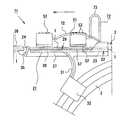
図1には、本実施形態のガイドワイヤ挿入補助具11と収納部2とが示されている。収納部2は二重または三重に巻かれた合成樹脂製のチューブからなり、その内部にはガイドワイヤ1が挿通されて収納されている。合成樹脂製のホルダ3は収納部2の巻回形状を保持する役割を果たしている。具体的にいうと、本実施形態のホルダ3は、略C字状のベース部4とそのベース部4の両端に設けられた一対の係止部5とを備えている。各係止部5には複数の係止溝6が形成され、その係止溝6に収納部2が嵌め込まれて係止している。ここで、本実施形態におけるガイドワイヤ1としては、ワイヤ表面に潤滑コートを付与した構造の潤滑ガイドワイヤが用いられている。ワイヤ表面には、所定長さごとにデプスマークが付されている。本実施形態ではワイヤ先端はJ字状に湾曲されたJ型となっている。なお、ワイヤ先端はJ型のほかアングル型やストレート型であってもよい。 FIG. 1 shows a guide
図1〜図3に示されるように、本実施形態のガイドワイヤ挿入補助具11は、合成樹脂製(例えばポリプロピレン製)の本体21を備えている。本体21は全体として前後方向に細長い形状を有している。本体21の基端部には収納部支持部22が一体的に設けられている。収納部支持部22の後端面にて開口する嵌合穴23には、収納部2の一端が着脱可能に嵌合されている。この嵌合により、収納部支持部22に収納部2が支持されている。 As shown in FIGS. 1 to 3, the guide
一方、本体21の先端部には、ガイドワイヤ支持部26が一体的に設けられている。ガイドワイヤ支持部26は、先端にいくほど縮径しており、先端にて開口した中空円筒状をなしている。ガイドワイヤ支持部26の内部には収納部2側から送り出されたガイドワイヤ1が挿通されている。その結果、ガイドワイヤ支持部26にガイドワイヤ1が支持されている。 On the other hand, a guide
本体21はその下面中央部に本体長手方向に沿って延びるリブ27を有している。このリブ27があることにより、本体21の剛性が全体的に高められている。本体21の下面には、下方に向って円弧状に延びる腕部31が一体的に突設されている。この腕部31の先端には断面略コ字状の保持部32が一体的に設けられている。保持部32は収納部2の外周面に係合することにより収納部2を保持している。その結果、ガイドワイヤ挿入補助具11と収納部2とが互いに位置ずれしにくくなる。また、術者がガイドワイヤ挿入補助具11を片手で把持する際に腕部31に親指F1以外の指を引っ掛けることができる。このため、術者がガイドワイヤ挿入補助具11を把持しやすくなる。 The
図1〜図3に示されるように、本体21において収納部支持部22とガイドワイヤ支持部26との間には、本体長手方向に沿って延びる摺接部28が配置されている。摺接部28における上面は、ガイドワイヤ1がその軸線方向に沿って摺接する摺接面29となっている。 As shown in FIGS. 1 to 3, a sliding
図3等に示されるように、本体21においてガイドワイヤ支持部26のある位置の近傍、より詳細にはガイドワイヤ支持部26の基端側開口の近傍には、本体21の上側に向って僅かに突出する凸部24が設けられている。そして、この凸部24がある位置に対応してゴムリング35が装着されている。ゴムリング35を凸部24よりも後側(図2,図3では右側)に配置した場合には、ゴムリング35がガイドワイヤ1に接触して固定される。ガイドワイヤ1には巻回状態から直線状態に戻ろうとする力が作用する。しかし、その力だけでガイドワイヤ1が自然に送り出されてしまうことはない。逆にゴムリング35を凸部24よりも前側(図2,図3では左側)に配置した場合には、ゴムリング35がガイドワイヤ1に対して非接触となる。その結果、ガイドワイヤ1が解放されて、上記の接触固定状態に比べてガイドワイヤ1が移動しやすくなる。 As shown in FIG. 3 and the like, in the vicinity of the position where the
図2,図3に示されるように、本体21において摺接部28のある箇所の上側には、一対の送出部材支持部42が互いに間隔を隔てて対向した状態で突設されている。一対の送出部材支持部42の上側部位には、本体長手方向に沿って延びる直線状のガイド部43がそれぞれ形成されている。一方の送出部材支持部42においては、ガイド部43の終端付近に係止突起44が形成されている。一対の送出部材支持部42の下側部位には、窓部45がそれぞれ形成されている。 As shown in FIGS. 2 and 3, a pair of delivery
一対の送出部材支持部42の間には、送出部材としての送出ブロック51が本体長手方向に沿って往復移動可能な状態で支持されている。送出ブロック51の下面には、保水性のある保水部材52が設けられている。なお、摺接部58の摺接面59側にも同様の保水部材57が設けられている。これら2つの保水部材52,57は、ガイドワイヤ1を挟持した状態で互いに対向配置されている。送出ブロック51の上面には、操作性の向上を目的として複数の滑り止め突条53が設けられている。送出ブロック51における一方の側面には、係止突起55が設けられている。この係止突起55はガイド部43に配置され、係止突起55の先端部はガイド部43を通り抜けて送出部材支持部42の外側に突出している。このような送出ブロック51側の係止突起55と、送出部材支持部42側の係止突起44との間には、付勢部材としてのコイルばね56が設けられている。そして、このコイルばね56は、送出ブロック51を本体21の基端部の方向に付勢するばね力を付与するものである。 A
保水部材52,57としては、保水性(吸水性)を有するばかりでなく、摩擦性(滑りにくい性質)を有する材質を用いて形成されることが好適である。具体的には、ナイロン製不織布やガーゼのような綿などが形成材料として好ましい。即ち、布のような繊維の集合体は、表面に微小な凹凸を有するため、適度な摩擦性が得られやすいという点で有利である。また、前記繊維の集合体は、繊維間に空隙を有するため、水分を保持しやすいという点で有利である。なお、繊維自体に吸水性があるようなものは、形成材料としてさらに好ましい。 The
以下、上記ガイドワイヤ挿入補助具11を利用したカテーテル挿入方法について説明する。 Hereinafter, a catheter insertion method using the guide
あらかじめ患者における挿入部位周囲の皮膚を消毒した後、挿入部に局所麻酔を施しておく。次に、ヘパリン加生理食塩液等を入れた注射筒を血管内留置用カニューレに装着し血管を穿刺する。血液の逆流を確認した後、血管内留置用カニューレの金属針を保持し、プラスチック製カニューレのみ血管内へ進め留置する。 Prior to disinfection of the skin around the insertion site in the patient, local anesthesia is applied to the insertion site. Next, a syringe containing heparinized physiological saline or the like is attached to an indwelling cannula, and the blood vessel is punctured. After confirming the backflow of blood, hold the metal needle of the cannula for indwelling the blood vessel and advance only the plastic cannula into the blood vessel.
次に、上記のガイドワイヤ挿入補助具11を用い、留置したカニューレにガイドワイヤ1を通し、ガイドワイヤ1を血管内へ挿入する。 Next, the
この場合、ガイドワイヤ1を収納した状態の収納部2の一端を収納部支持部22の嵌合穴23に嵌合させておくとともに、収納部2の内部を他端から注入したヘパリン加生理食塩液であらかじめ満たしておく。必要に応じて、あらかじめ保水部材52,57に生理食塩液またはヘパリン加生理食塩液を含ませておいてもよい。このとき、ゴムリング35はまだ凸部24よりも後側に配置され、ガイドワイヤ1が自然に送り出されないように固定している。なお、ガイドワイヤ1の先端がガイドワイヤ支持部26内にあることを確認しておく。 In this case, one end of the
ここで、術者はガイドワイヤ支持部26が前側になるように本体21を片手の指で挟むようにして把持する。そして、ガイドワイヤ支持部26の先端をプラスチック製カニューレに入れるとともに、親指F1でゴムリング35を押し上げて凸部24よりも前側に配置させる。そして、この状態でガイドワイヤ1の送り出し操作を行う。具体的には、図3に示されるように、親指F1の腹を送出ブロック51の上面に当て、送出ブロック51を下方に押圧しながら本体先端側にスライド移動させる(つまり往動させる)。すると、送出ブロック51側の保水部材52と摺接面59側の保水部材57との間にガイドワイヤ1が挟持される。そして、送出ブロック51の移動に伴ってガイドワイヤ1が送り出される。このときガイドワイヤ1には保水部材52,57が接触する。このため、ガイドワイヤ1の表面の生理食塩液またはヘパリン加生理食塩液が乾いてしまうこともなく潤滑性が維持される。なお、本体先端側にスライド移動させた送出ブロック51から親指F1を離せば、コイルばね56のばね力によって送出ブロック1が自動的に復動して元の位置に戻る。 Here, the surgeon holds the
以上の送り出し操作を行う結果、ガイドワイヤ1がカニューレを介して血管内に挿入される。このような操作を行う場合、ガイドワイヤ1が目的の位置にあるかをX線撮影により確認することがよい。 As a result of performing the above feeding operation, the
ガイドワイヤ1の挿入が完了したら、カニューレを抜き取り、皮膚切開用刀で刺入部に外科的小切開を加える。ここで、ダイレータをガイドワイヤ1に沿わせて押し進めることで、皮下組織と血管刺入口とを十分に拡張する。拡張後はダイレータを抜去する。続いて、内腔をヘパリン加生理食塩液で満たしたカテーテルをガイドワイヤ1に沿ってゆっくりと挿入する。その際、デプスマークを確認しながら目的留置位置までカテーテルを押し進める。カテーテルが目的の位置に留置されたことを確認したら、ガイドワイヤ1を抜去する。次に、常法によりカテーテル内腔の空気を除去し、血液凝固を防ぐために内腔を生理食塩液またはヘパリン加生理食塩液でフラッシュする。その際、カテーテルが体内でループを描いたりしていないか、カテーテル先端が目的の位置にあるかをX線撮影下で確認することが好ましい。この後、カテーテルをカテーテル固定具及び糸付き縫合針並びにドレッシングで固定し、一連のカテーテル挿入作業を完了する。 When the insertion of the
以上述べたように本実施形態によれば下記の作用効果を奏する。
(1)本実施形態のガイドワイヤ挿入補助具11によると、送出ブロック51による送り出し操作の際、保水部材52,57がガイドワイヤ1に接触する。その結果、ガイドワイヤ1を潤滑性を保ちつつ本体先端側に送り出すことができる。また、この構成によれば、術者がガイドワイヤ1を親指F1で直接触ることなく送り出すことができる。ゆえに、従来のガイドワイヤ挿入補助具を用いた場合とは異なり、術者の親指F1がガイドワイヤ1及び摺接面29の上にて滑ってしまうようなことがない。しかも、親指F1が接触することで部分的に潤滑性が損なわれてしまうといった心配もない。As described above, according to this embodiment, the following operational effects can be obtained.
(1) According to the guide wire
以上のように、このガイドワイヤ挿入補助具11によれば、潤滑性を発現させたガイドワイヤ1を片手で簡単に送り出すことできる。このため、術中に両手が塞がってしまうこともなく、操作性に優れたものとすることができる。 As described above, according to the guide wire
(2)本実施形態のガイドワイヤ挿入補助具11によれば、送出ブロック1の送り出し操作後に親指F1を離せば、コイルばね56のばね力によって送出ブロック1が自動的に復動して元の位置に戻るようになっている。従って、わざわざ親指F1で送出ブロック51を戻す必要がなく、操作性がよりいっそう向上する。 (2) According to the guide
(3)本実施形態のガイドワイヤ挿入補助具11は、ゴムリング35及び凸部24を備えている。このため、必要に応じてガイドワイヤ1を飛び出し不能に固定しておくことができる。従って、例えば輸送時の振動によってガイドワイヤ挿入補助具11の先端からガイドワイヤ1が飛び出すような事態を未然に防ぐことができる。従って、信頼性に優れたものとすることができる。 (3) The guide
(4)本実施形態のガイドワイヤ挿入補助具11では、一対の送出部材支持部42間に送出ブロック51を挟み込んで配置し、送出部材支持部42に直線状のガイド部43を設け、そのガイド部43に係止突起55を配置した構造を採用している。ゆえに、送出ブロック51が一対の送出部材支持部42に支持された状態でガイド部43によってガイドされる。このため、本体長手方向に沿った往復移動を確実にかつスムーズに行わせることができる。 (4) In the guide wire
ところで、図4には、第1の実施形態の変更例にかかるガイドワイヤ挿入補助具11Aが示されている。この変更例ではガイド部43の形状が若干異なっている。即ち、ガイド部43の先端側には、下方に曲がった湾曲部43aが形成されている。従って、送出ブロック51を本体先端側いっぱいまで移動させた後、係止突起55を湾曲部43aに落とし込むようにして係止させることができる。その結果、送出ブロック51が本体先端側の位置にて移動不能に保持される。また、送出ブロック51側の保水部材52と摺接面59側の保水部材57との距離が縮まる。このため、両者間にガイドワイヤ1を確実に挟持してガイドワイヤ1を移動不能とすることができる。ゆえに、この構成によれば、送出ブロック51が送出部材として機能するばかりでなく、ガイドワイヤ固定部材としても機能する。 FIG. 4 shows a guide wire
[第2の実施形態]
以下、本発明を具体化した第2の実施形態のガイドワイヤ挿入補助具71を図5,図6に基づいて詳細に説明する。[Second Embodiment]
Hereinafter, a guide wire
図5に示されるように、本実施形態のガイドワイヤ挿入補助具71は、保水部材52を下面に有する送出ブロック51を備えている。しかし、その送出ブロック51を支持するための構造である送出部材支持部42を備えていない。それに代わる支持構造として、ガイドワイヤ挿入補助具71は、送出ブロック51と本体21側とを連結する連結部材72を備えている。本実施形態の連結部材72は可撓性を有する帯状部材であり、途中に略U字状の湾曲部73を備えている。ここでは連結部材72が、本体21における収納部支持部22の上面に一体的に設けられている。従って、本実施形態では本体21と連結部材72とが共通の合成樹脂材料(ポリプロピレン)からなる。なお、連結部材72はさらに送出ブロック51と一体的に設けられていてもよい。 As shown in FIG. 5, the guide wire
このガイドワイヤ挿入補助具71を使用する場合には、送出ブロック51の保水部材52側と摺接部28側の保水部材57側との間にガイドワイヤ1を挟持する。そしてこの状態で送出ブロック51を親指F1で往復移動させる。その結果、送出ブロック51を介してガイドワイヤ1を本体先端側に送り出すことができる。可撓性を有する連結部材72は、本体21と送出ブロック51とを連結しているものの、送出ブロック51の往復移動時に主として湾曲部73が伸縮変形することができる(図6参照)。そのため、往復移動時に支障をきたさないという利点がある。また、この構造によると、送出部材を別体で設ける場合に比較して、部品点数が少なくて済み、簡単な構造とすることができるという利点がある。 When this guide wire
[第3の実施形態]
以下、本発明を具体化した第3の実施形態のガイドワイヤ挿入補助具81を図7に基づいて詳細に説明する。[Third Embodiment]
Hereinafter, a guide
図7に示されるように、本実施形態のガイドワイヤ挿入補助具81では、一対の送出部材支持部42が設けられている。しかし、それらが支持している送出部材の構造が大きく異なっている。即ち本実施形態では、無端状の送出ベルト82を送出部材として用いている。この送出ベルト82は外周面の全域に保水部材52を有している。送出ベルト82において下面に位置している保水部材52は、摺接部28側の保水部材57と対面している。一対の送出部材支持部42の内側面における4箇所には、巻回突起84が設けられている。これら巻回突起84には送出ベルト82が掛け渡されている。その結果、送出ベルト82が周回移動可能な状態で一対の送出部材支持部42間に支持されている。 As shown in FIG. 7, the guide wire
このガイドワイヤ挿入補助具81を使用する場合には、送出ベルト82の保水部材52側と摺接部28側の保水部材57側との間にガイドワイヤ1を挟持する。そしてこの状態で送出ベルト82を親指F1で操作して周回移動させる。その結果、送出ベルト82を介してガイドワイヤ1を本体先端側に送り出すことができる。なお、親指F1で操作する部位は、送出ベルト82の内周面側であってもよく、外周面側であってもよい。なお、本実施形態の構成によると、送出ベルト82側の保水部材52を大きくすることができる。このため、ガイドワイヤ1に対してより効率よく確実に潤滑性を付与できるという利点がある。 When this guide
なお、本発明の実施形態は以下のように変更してもよい。 In addition, you may change embodiment of this invention as follows.
・上記第1、第2実施形態では、送出ブロック51の上面に複数の滑り止め突条53を設けたが、突起、穴、溝などといった滑り止め構造を採用してもよい。また、第3実施形態について、例えば送出ベルト82の内周面側にこのような滑り止め構造を設けてもよい。 In the first and second embodiments, a plurality of
・上記第1実施形態では、付勢部材としてのコイルばね56を設けたが、圧縮ばね及び引っ張りばねのいずれのタイプを使用することも可能である。また、他の付勢部材として、コイルばね56以外の形式のばね(例えば板ばね等)を使用することも許容される。 In the first embodiment, the
・上記第2実施形態では、連結部材72を本体21における収納部支持部22の上面に一体的に設けたが、本体21における別の位置に設けることもできる。また、連結部材72は必ずしも本体21と一体的に設けられなくてもよく、別体で作製したものを設けるようにしてもよい。また、連結部材72の形状は上記第2実施形態のものに限定されず、任意に変更することができる。 In the second embodiment, the connecting
・上記第3実施形態では、送出部材として送出ベルト82を用いていた。これに代えて、送出ベルト82とは異なるタイプの転動体(例えば送出ローラなど)を用い、これと摺接面59との間にガイドワイヤ1を挟み込んで当該転動体を転動させるようにしてもよい。 In the third embodiment, the
・上記第1〜第3実施形態では、ガイドワイヤ固定部材としてゴムリング35を用いたが、必ずしもこれに限定されない。例えば、ゴム以外の素材からなるリング状物や、リング状ではないゴム製部材などの使用も可能である。即ち、ガイドワイヤ1に対して接離することにより、ガイドワイヤを固定または解放することができる部材であれば、その材質や形状は問わない。 -In the said 1st-3rd embodiment, although the
・上記第1〜第3実施形態では、送出部材側の保水部材52及び摺動部58側の保水部材57の2つを設けたが、摺動部58側の保水部材57を省略してもよい。 In the first to third embodiments, the
・上記第1〜第3実施形態では、円弧状に延びる腕部31及び保持部32を設けたが、これらを省略してもよい。 In the first to third embodiments, the
なお、本発明の実施形態から把握される技術的思想を以下に列挙する。 The technical ideas grasped from the embodiments of the present invention are listed below.
(1)上記手段3において、前記送出ブロックは、前記ガイドワイヤを固定するためのガイドワイヤ固定部材としても機能すること。 (1) In the above means 3, the delivery block also functions as a guide wire fixing member for fixing the guide wire.
(2)上記手段1乃至6のいずれか1項において、前記本体の下面には下方に向って円弧状に延びる腕部が突設され、前記腕部の先端には収納部を保持するための保持部が設けられていること。 (2) In any one of the above means 1 to 6, the lower surface of the main body is provided with an arm portion extending downward in a circular arc shape, and a holding portion is held at the tip of the arm portion A holding part is provided.
(3)上記手段1乃至6のいずれか1項において、前記本体において前記ガイドワイヤ支持部の基端側開口の近傍には凸部が設けられ、前記凸部がある位置に対応して前記ガイドワイヤを固定または解放するためのゴムリングが装着されていること。 (3) In any one of the above means 1 to 6, in the main body, a convex portion is provided in the vicinity of the proximal end side opening of the guide wire support portion, and the guide corresponds to a position where the convex portion is located. A rubber ring is attached to secure or release the wire.
1…ガイドワイヤ
2…収納部
11,11A,71,81…ガイドワイヤ挿入補助具
21…本体
22…収納部支持部
26…ガイドワイヤ支持部
28…摺接部
29…摺接面
42…送出部材支持部
43…ガイド部
51…送出部材としての送出ブロック
52,57…保水部材
56…付勢部材としてのコイルばね
72…連結部材
82…送出部材としての送出ベルトDESCRIPTION OF
Claims (6)
Translated fromJapanese先端部及び基端部を有する本体と、
前記本体に対して前記収納部を着脱可能に支持するべく前記基端部に設けられた収納部支持部と、
先端が開口した筒状をなし、前記収納部から送り出した前記ガイドワイヤを挿通させて支持するべく前記先端部に設けられたガイドワイヤ支持部と、
前記収納部支持部と前記ガイドワイヤ支持部との間に配置され、本体長手方向に沿って延びかつ前記ガイドワイヤの摺接面を有する摺接部と、
前記本体に設けられ、保水性のある保水部材を有する送出部材と
を備え、前記送出部材は、前記保水部材側を前記摺接面側に対向させて配置されるとともに、前記摺接部との間に前記ガイドワイヤを挟持した状態で変位可能であることを特徴とするガイドワイヤ挿入補助具。Auxiliary tool for sending out a guide wire inserted into the storage unit and inserting it into the lumen of the medical device,
A body having a distal end and a proximal end;
A storage portion support portion provided at the base end portion to removably support the storage portion with respect to the main body;
A guide wire support portion provided at the tip portion to form a cylindrical shape with an open tip and to insert and support the guide wire sent out from the storage portion;
A sliding contact portion disposed between the storage portion support portion and the guide wire support portion, extending along a longitudinal direction of the main body and having a sliding contact surface of the guide wire;
A feed member having a water retention member with water retention, and the feed member is disposed with the water retention member side facing the sliding contact surface side, and with the sliding contact portion A guide wire insertion aid that is displaceable with the guide wire sandwiched therebetween.
前記送出部材は、前記保水部材を下面に有する送出ブロックであり、かつ、前記本体長手方向に沿って往復移動可能な状態で前記送出部材支持部に支持されている
ことを特徴とする請求項1に記載のガイドワイヤ挿入補助具。On the upper side of the portion where the sliding contact portion is located in the main body, a delivery member support portion having a guide portion extending along the longitudinal direction of the main body is provided,
The said delivery member is a delivery block which has the said water retention member in the lower surface, and is supported by the said delivery member support part in the state which can reciprocate along the said main body longitudinal direction. The guide wire insertion aid described in 1.
前記送出部材は、前記保水部材を外周面に有する無端状の送出ベルトであり、かつ、周回移動可能な状態で前記送出部材支持部に支持されている
ことを特徴とする請求項1に記載のガイドワイヤ挿入補助具。On the upper side of the portion where the sliding contact portion is located in the main body, a delivery member support portion is provided,
The said delivery member is an endless delivery belt which has the said water retention member in an outer peripheral surface, and is supported by the said delivery member support part in the state which can be circulated, The Claim 1 characterized by the above-mentioned. Guide wire insertion aid.
Priority Applications (6)
| Application Number | Priority Date | Filing Date | Title |
|---|---|---|---|
| JP2010213532AJP2012065871A (en) | 2010-09-24 | 2010-09-24 | Guidewire insertion aid |
| US13/214,530US9011351B2 (en) | 2010-09-24 | 2011-08-22 | Guidewire insertion aid |
| EP11180406AEP2433670A1 (en) | 2010-09-24 | 2011-09-07 | Guidewire Insertion Aid |
| MX2011009502AMX2011009502A (en) | 2010-09-24 | 2011-09-09 | Guidewire insertion aid. |
| CN201110284651.4ACN102440840B (en) | 2010-09-24 | 2011-09-23 | Guidewire insertion aid |
| US14/688,054US9545504B2 (en) | 2010-09-24 | 2015-04-16 | Guidewire insertion aid |
Applications Claiming Priority (1)
| Application Number | Priority Date | Filing Date | Title |
|---|---|---|---|
| JP2010213532AJP2012065871A (en) | 2010-09-24 | 2010-09-24 | Guidewire insertion aid |
Publications (1)
| Publication Number | Publication Date |
|---|---|
| JP2012065871Atrue JP2012065871A (en) | 2012-04-05 |
Family
ID=44651258
Family Applications (1)
| Application Number | Title | Priority Date | Filing Date |
|---|---|---|---|
| JP2010213532APendingJP2012065871A (en) | 2010-09-24 | 2010-09-24 | Guidewire insertion aid |
Country Status (5)
| Country | Link |
|---|---|
| US (2) | US9011351B2 (en) |
| EP (1) | EP2433670A1 (en) |
| JP (1) | JP2012065871A (en) |
| CN (1) | CN102440840B (en) |
| MX (1) | MX2011009502A (en) |
Cited By (2)
| Publication number | Priority date | Publication date | Assignee | Title |
|---|---|---|---|---|
| WO2014010335A1 (en)* | 2012-07-13 | 2014-01-16 | オリンパスメディカルシステムズ株式会社 | Treatment system for endoscope |
| WO2016152378A1 (en)* | 2015-03-25 | 2016-09-29 | テルモ株式会社 | Catheter assembly |
Families Citing this family (65)
| Publication number | Priority date | Publication date | Assignee | Title |
|---|---|---|---|---|
| EP1907042B1 (en) | 2005-07-06 | 2009-03-11 | Vascular Pathways Inc. | Intravenous catheter insertion device and method of use |
| EP2150304B1 (en) | 2007-05-07 | 2010-12-01 | Vascular Pathways Inc. | Intravenous catheter insertion and blood sample devices and method of use |
| US10219832B2 (en) | 2007-06-29 | 2019-03-05 | Actuated Medical, Inc. | Device and method for less forceful tissue puncture |
| US9987468B2 (en)* | 2007-06-29 | 2018-06-05 | Actuated Medical, Inc. | Reduced force device for intravascular access and guidewire placement |
| US10384039B2 (en) | 2010-05-14 | 2019-08-20 | C. R. Bard, Inc. | Catheter insertion device including top-mounted advancement components |
| US8932258B2 (en) | 2010-05-14 | 2015-01-13 | C. R. Bard, Inc. | Catheter placement device and method |
| US9872971B2 (en) | 2010-05-14 | 2018-01-23 | C. R. Bard, Inc. | Guidewire extension system for a catheter placement device |
| US9950139B2 (en) | 2010-05-14 | 2018-04-24 | C. R. Bard, Inc. | Catheter placement device including guidewire and catheter control elements |
| US11925779B2 (en) | 2010-05-14 | 2024-03-12 | C. R. Bard, Inc. | Catheter insertion device including top-mounted advancement components |
| JP2012065871A (en) | 2010-09-24 | 2012-04-05 | Nihon Covidien Kk | Guidewire insertion aid |
| US8690833B2 (en) | 2011-01-31 | 2014-04-08 | Vascular Pathways, Inc. | Intravenous catheter and insertion device with reduced blood spatter |
| ES2835652T3 (en) | 2011-02-25 | 2021-06-22 | Bard Inc C R | Medical component insertion device including a retractable needle |
| USD903101S1 (en) | 2011-05-13 | 2020-11-24 | C. R. Bard, Inc. | Catheter |
| WO2014120741A1 (en) | 2013-01-30 | 2014-08-07 | Vascular Pathways, Inc. | Systems and methods for venipuncture and catheter placement |
| US10357635B2 (en) | 2013-03-12 | 2019-07-23 | Teleflex Medical Incorporated | Catheter insertion device |
| US9717886B2 (en) | 2013-03-12 | 2017-08-01 | Teleflex Medical Incorporated | Safety clip for a needle |
| US11224724B2 (en) | 2013-03-12 | 2022-01-18 | Teleflex Medical Incorporated | Catheter insertion device |
| JP2014212906A (en)* | 2013-04-25 | 2014-11-17 | 日本コヴィディエン株式会社 | Guide wire insertion aid |
| US9375553B2 (en)* | 2013-04-25 | 2016-06-28 | Freddy Dwight CHRISMAN | Compression torque device |
| US20160175564A1 (en)* | 2013-08-05 | 2016-06-23 | Vascular Imaging Corporation | Guidewire torque handle |
| WO2015023358A1 (en) | 2013-08-14 | 2015-02-19 | Teleflex Medical Incorporated | Catheter insertion device |
| WO2016037127A1 (en) | 2014-09-05 | 2016-03-10 | C.R. Bard, Inc. | Catheter insertion device including retractable needle |
| JP6623170B2 (en) | 2014-12-02 | 2019-12-18 | テルモ株式会社 | Catheter holder and catheter set |
| WO2016123022A1 (en)* | 2015-01-26 | 2016-08-04 | Sos Thomas A | Guidewire clamp and introducer |
| ES2975734T3 (en) | 2015-01-29 | 2024-07-12 | Becton Dickinson Co | Integrated Quick Insert Catheter |
| USD903100S1 (en) | 2015-05-01 | 2020-11-24 | C. R. Bard, Inc. | Catheter placement device |
| CN113350614A (en) | 2015-05-15 | 2021-09-07 | C·R·巴德股份有限公司 | Catheter placement device including extendable needle safety feature |
| US10940292B2 (en) | 2015-07-08 | 2021-03-09 | Actuated Medical, Inc. | Reduced force device for intravascular access and guidewire placement |
| US11793543B2 (en) | 2015-09-18 | 2023-10-24 | Obvius Robotics, Inc. | Device and method for automated insertion of penetrating member |
| AU2017221239B2 (en)* | 2016-02-21 | 2021-09-23 | Samuel S. SHIELDS | Winguide and method of using same |
| USD785792S1 (en)* | 2016-03-28 | 2017-05-02 | Smiths Medical Asd, Inc. | Guidewire introducer |
| US11413433B2 (en) | 2016-04-17 | 2022-08-16 | Acantha Medical, LLC | Device and method for single-handed access and insertion of an article |
| CA3021313A1 (en) | 2016-04-17 | 2017-10-26 | Acantha Medical, Inc. | Device and method for single-handed access and insertion of an article |
| KR101834784B1 (en)* | 2016-05-20 | 2018-04-19 | (주)에스엠허스 | Pre-jellied the tube holder for medical treatment |
| US10493262B2 (en) | 2016-09-12 | 2019-12-03 | C. R. Bard, Inc. | Blood control for a catheter insertion device |
| US10582937B2 (en) | 2016-10-24 | 2020-03-10 | Thomas Gast | Medical guide wire device for endovascular-intraluminal devices |
| US10478599B2 (en) | 2016-11-17 | 2019-11-19 | Vascugenix LLC | Compression torque device |
| EP3585471B1 (en) | 2017-03-01 | 2025-01-01 | C. R. Bard, Inc. | Catheter insertion device |
| EP4480525A3 (en) | 2017-04-13 | 2025-04-09 | Teleflex Medical Incorporated | Catheter insertion device |
| WO2019048929A2 (en) | 2017-09-05 | 2019-03-14 | Bowline Medical Pty Ltd | Catheter and guidewire advancement device |
| US11090462B2 (en) | 2017-09-05 | 2021-08-17 | Andrew DYALL | Advancement or retraction device |
| CN107753102B (en)* | 2017-11-23 | 2020-04-10 | 王凯 | Guide wire insertion device for trigeminal interventional therapy for neurosurgery |
| ES2980192T3 (en) | 2018-03-07 | 2024-09-30 | Bard Access Systems Inc | Guidewire advancement and blood reflux systems for a medical device insertion system |
| USD921884S1 (en) | 2018-07-27 | 2021-06-08 | Bard Access Systems, Inc. | Catheter insertion device |
| CA3151126A1 (en) | 2019-08-19 | 2021-02-25 | Becton, Dickinson And Company | Midline catheter placement device |
| US11890429B2 (en) | 2019-09-10 | 2024-02-06 | Bard Access Systems, Inc. | Rapidly inserted central catheter and methods thereof |
| BR112022005254A2 (en) | 2019-09-24 | 2022-06-14 | Bard Access Systems Inc | Acute central venous catheter and peripherally inserted venous catheter integrated |
| WO2021081434A1 (en)* | 2019-10-25 | 2021-04-29 | Bard Access Systems, Inc. | Guidewire-management devices and methods thereof |
| CA3168492A1 (en) | 2020-01-23 | 2021-07-29 | Bard Access Systems, Inc. | Splitable catheter docking station system |
| KR20220153062A (en) | 2020-03-13 | 2022-11-17 | 바드 액세스 시스템즈, 인크. | GUIDEWIRE-MANAGEMENT DEVICES AND METHODS THEREOF |
| CN113384798A (en)* | 2020-03-13 | 2021-09-14 | 巴德阿克塞斯系统股份有限公司 | Guide wire management device and method thereof |
| EP4135819A1 (en) | 2020-04-23 | 2023-02-22 | Bard Access Systems, Inc. | Rapidly insertable central catheters including catheter assemblies |
| WO2021236950A1 (en) | 2020-05-21 | 2021-11-25 | Bard Access Systems, Inc. | Rapidly insertable central catheters including catheter assemblies |
| AU2021303150B2 (en) | 2020-06-29 | 2025-10-02 | Bard Access Systems, Inc. | Rapidly insertable central catheters including catheter assemblies and methods thereof |
| CA3186461A1 (en) | 2020-06-29 | 2022-01-06 | Bard Access Systems, Inc. | Rapidly insertable central catheters including assemblies |
| US12048818B2 (en) | 2020-07-05 | 2024-07-30 | New Wave Endo-Surgical Corp. | Handheld elongate medical device advancer and related systems, devices and methods |
| AU2021371314B2 (en) | 2020-10-28 | 2025-09-25 | Bard Access Systems, Inc. | Catheter placement system with stiffening system |
| AU2021400331B2 (en) | 2020-12-17 | 2025-09-25 | Bard Access Systems, Inc. | Rapidly insertable central catheters and assemblies |
| EP4259256A1 (en) | 2020-12-21 | 2023-10-18 | Bard Access Systems, Inc. | Fluid path optimization in catheter insertion systems |
| EP4259254A1 (en) | 2020-12-21 | 2023-10-18 | Bard Access Systems, Inc. | Optimized structural support in catheter insertion systems |
| CN113230520B (en)* | 2021-06-09 | 2022-09-06 | 王�琦 | Guide wire insertion device for nerve intervention |
| USD1084319S1 (en) | 2021-07-06 | 2025-07-15 | New Wave Endo-Surgical Corp. | Medical elongate advancer |
| CN114887196B (en)* | 2022-05-11 | 2023-11-24 | 中国人民解放军联勤保障部队第九〇四医院 | Coronary intervention guide wire catheter fixing device capable of achieving disinfection and lubrication |
| CN115540948A (en)* | 2022-10-20 | 2022-12-30 | 微亚医疗科技(苏州)有限公司 | Methods for detecting guidewire delivery speed and guidewire delivery resistance |
| US12426965B2 (en) | 2023-06-15 | 2025-09-30 | Obvius Robotics, Inc. | Image-guided robotic arm for inserting a penetrating member into a body lumen |
Citations (3)
| Publication number | Priority date | Publication date | Assignee | Title |
|---|---|---|---|---|
| JPH05208051A (en)* | 1991-11-06 | 1993-08-20 | Imagyn Medical Inc | External rotation type catheter apparatus and controller therefor |
| US5242428A (en)* | 1991-10-04 | 1993-09-07 | Aubrey Palestrant | Apparatus for wetting hydrophilic-coated guide wires and catheters |
| JP2002282275A (en)* | 2001-03-26 | 2002-10-02 | Medikit Kk | Catheter storing case |
Family Cites Families (80)
| Publication number | Priority date | Publication date | Assignee | Title |
|---|---|---|---|---|
| US3561445A (en) | 1968-07-03 | 1971-02-09 | Abbott Lab | Catheter placement unit |
| US3995628A (en) | 1975-04-25 | 1976-12-07 | Travenol Laboratories, Inc. | Catheter insertion device |
| US4860757A (en) | 1987-10-28 | 1989-08-29 | Medical Parameters, Incorporated | Guidewire advancement system |
| US5186179A (en) | 1987-10-28 | 1993-02-16 | Medical Parameters, Inc. | Guidewire advancement system |
| US4917094A (en) | 1987-10-28 | 1990-04-17 | Medical Parameters Inc. | Guidewire advancement system |
| US5273042A (en) | 1987-10-28 | 1993-12-28 | Medical Parameters, Inc. | Guidewire advancement method |
| US5137517A (en) | 1989-11-28 | 1992-08-11 | Scimed Life Systems, Inc. | Device and method for gripping medical shaft |
| US5484419A (en) | 1990-11-02 | 1996-01-16 | Arrow International Investment Corporation | Hand-held device for feeding a spring wire guide |
| US5125906A (en) | 1990-11-02 | 1992-06-30 | Arrow International Investment Corporation | Hand-held device for feeding a spring wire guide |
| US5125905A (en) | 1991-06-27 | 1992-06-30 | Boc Health Care, Inc. | Guidewire straightener |
| US5137288A (en) | 1991-07-22 | 1992-08-11 | Cordis Corporation | Side loading wire grip |
| US5161534A (en) | 1991-09-05 | 1992-11-10 | C. R. Bard, Inc. | Tool for manipulating a medical guidewire |
| US5325746A (en) | 1991-09-27 | 1994-07-05 | Cook Incorporated | Wire guide control handle |
| US5279573A (en) | 1991-11-04 | 1994-01-18 | Lake Region Manufacturing Company, Inc. | Guidewire containment apparatus and method |
| US5263938A (en) | 1992-01-28 | 1993-11-23 | Becton, Dickinson And Company | Guidewire introducer assembly |
| US5282479A (en) | 1992-10-13 | 1994-02-01 | Boc Health Care, Inc. | Guidewire introducer with guidewire grasp and release means |
| US5462527A (en) | 1993-06-29 | 1995-10-31 | C.R. Bard, Inc. | Actuator for use with steerable catheter |
| US5318541A (en) | 1993-03-02 | 1994-06-07 | Cordis Corporation | Apparatus for catheter exchange in vascular dilitation |
| US5454785A (en) | 1993-04-12 | 1995-10-03 | C. R. Bard, Inc. | Method of withdrawing and exchanging catheters |
| US5325868A (en) | 1993-05-04 | 1994-07-05 | Kimmelstiel Carey D | Self-gripping medical wire torquer |
| JPH0722752A (en) | 1993-06-30 | 1995-01-24 | Matsushita Electric Ind Co Ltd | Multilayer ceramic substrate and manufacturing method thereof |
| US5366444A (en) | 1993-07-06 | 1994-11-22 | Med-Pro Design, Inc. | Hand operated guide wire advancement device |
| US5366441A (en) | 1993-09-28 | 1994-11-22 | Becton, Dickinson And Company | Catheter introducer assembly with guidewire |
| CA2132890C (en) | 1993-09-30 | 1999-04-06 | Timothy J. Erskine | Peristaltic interlumenar device advancer |
| JP2601155Y2 (en) | 1993-10-06 | 1999-11-08 | 日本シャーウッド株式会社 | Guide wire insertion aid |
| US5634475A (en) | 1994-09-01 | 1997-06-03 | Datascope Investment Corp. | Guidewire delivery assist device and system |
| ATE269739T1 (en) | 1994-12-28 | 2004-07-15 | Abbott Lab | INTRODUCTION DEVICE WITH VALVE FOR A CATHETER |
| US5730150A (en) | 1996-01-16 | 1998-03-24 | B. Braun Medical Inc. | Guidewire dispenser |
| US5800389A (en) | 1996-02-09 | 1998-09-01 | Emx, Inc. | Biopsy device |
| US5843002A (en) | 1996-06-10 | 1998-12-01 | Baxter International Inc. | Guide wire dispenser apparatus and method |
| US5827202A (en) | 1996-06-10 | 1998-10-27 | Baxter International Inc. | Guide wire dispenser apparatus and method |
| US6139540A (en) | 1997-10-30 | 2000-10-31 | Lake Region Manufacturing, Inc. | Guidewire with disposition to coil |
| US6093179A (en) | 1998-01-21 | 2000-07-25 | Abbott Laboratories | Apparatus and method for placement of a percutaneous endoscopic gastrostomy tube |
| US6030349A (en) | 1998-02-23 | 2000-02-29 | Cartika Medical, Inc. | Medical guide wire torquer |
| US20070225615A1 (en) | 2006-03-22 | 2007-09-27 | Revascular Therapeutics Inc. | Guidewire controller system |
| US6190333B1 (en) | 1999-10-15 | 2001-02-20 | Mark Ii Research And Development Corp. | Threader device for threading a guidewire into a catheter |
| US6511470B1 (en) | 1999-11-30 | 2003-01-28 | Scimed Life Systems, Inc. | Apparatus and method for steering a guidewire and connecting to an extension guidewire |
| US6551281B1 (en) | 2000-01-13 | 2003-04-22 | Medical Components, Inc. | Guide wire advancer and assembly and method for advancing a guide wire |
| US6533772B1 (en) | 2000-04-07 | 2003-03-18 | Innex Corporation | Guide wire torque device |
| US6641563B1 (en) | 2000-11-01 | 2003-11-04 | Arrow International, Inc. | Stylet-free epidural catheter and thread assist device |
| US6582390B1 (en) | 2000-11-08 | 2003-06-24 | Endovascular Technologies, Inc. | Dual lumen peel-away sheath introducer |
| US20030036712A1 (en) | 2001-08-15 | 2003-02-20 | Heh Kok Boon | Roller wheel assisted guidewire advancer |
| US7604611B2 (en) | 2001-10-19 | 2009-10-20 | C.R. Bard, Inc. | Handle thumb wheel mechanism which maintains holding forces when sterilized and when engaged |
| US6558060B1 (en)* | 2002-01-11 | 2003-05-06 | Seshadri Raju | Catheter guidewire lubricating device |
| US7182756B2 (en) | 2002-05-29 | 2007-02-27 | Wilson-Cook Medical, Inc. | Device for directing a wire guide |
| US6949104B2 (en)* | 2002-05-31 | 2005-09-27 | Jack Griffis | Guide wire steering handle |
| US20040006329A1 (en) | 2002-07-05 | 2004-01-08 | Scheu Rolf Rainer | Device for holding and guiding a guide wire in a catheter |
| US20040122416A1 (en) | 2002-12-18 | 2004-06-24 | Medical Components, Inc. | Locking guidewire straightener |
| US7455660B2 (en) | 2002-12-18 | 2008-11-25 | Medical Components, Inc. | Locking guidewire straightener |
| DE20304533U1 (en) | 2003-03-21 | 2004-08-05 | Impella Cardiosystems Ag | An insertion device for inserting an object into a body vessel |
| US20040230136A1 (en) | 2003-05-14 | 2004-11-18 | Corrigan Richard F. | Guidewire having axially extending flow through passageways |
| US7191900B2 (en) | 2003-06-03 | 2007-03-20 | Js Vascular, Inc. | Guide wire containment and dispensing apparatus |
| US7717865B2 (en) | 2003-09-30 | 2010-05-18 | Boston Scientific Scimed, Inc. | Side loading wire torquing device |
| US7144378B2 (en) | 2003-10-31 | 2006-12-05 | Arnott Richard J | Quick-release torquer apparatus for delivering and maintaining a medical guideware |
| US7357787B2 (en) | 2003-12-18 | 2008-04-15 | Unomedial Limited | Guiding and positioning device and a system for positioning a catheter within a vein by means of the device |
| US7229420B2 (en)* | 2003-12-23 | 2007-06-12 | Cytyc Corporation | Medical instrument for accessing a breast duct for performing a medical procedure |
| US20050171568A1 (en) | 2004-01-30 | 2005-08-04 | Niall Duffy | Catheter and guidewire exchange system with improved catheter design |
| US7334678B2 (en) | 2004-02-13 | 2008-02-26 | Boston Scientific Scimed, Inc. | Guidewire hoops and methods pertaining thereto |
| EP1570878B1 (en) | 2004-03-01 | 2008-06-11 | Terumo Kabushiki Kaisha | Device for introduction of long medical item |
| JP4473266B2 (en) | 2004-03-15 | 2010-06-02 | テルモ株式会社 | Guide wire assembly |
| US7615032B2 (en) | 2004-03-24 | 2009-11-10 | Windcrest Llc | Vascular guidewire control apparatus |
| EP1727587A1 (en) | 2004-03-24 | 2006-12-06 | Windcrest LLC | Energizer for vascular guidewire |
| JP2005312976A (en) | 2004-04-30 | 2005-11-10 | Cook Inc | Wire guide apparatus |
| US7758564B2 (en) | 2004-05-14 | 2010-07-20 | Ethicon Endo-Surgery, Inc. | Medical instrument having a catheter and a medical guidewire |
| WO2005113051A2 (en) | 2004-05-14 | 2005-12-01 | Ethicon Endo-Surgery, Inc. | Medical instrument having a medical guidewire |
| US20060025721A1 (en) | 2004-07-30 | 2006-02-02 | Niall Duffy | Catheter and guidewire exchange system with improved catheter design |
| US20060149292A1 (en) | 2004-12-30 | 2006-07-06 | Merril Knudtson | Device for facilitating the insertion of a guidewire into the tip of intervascular guidewire guided device |
| EP1845872B1 (en) | 2005-02-02 | 2010-10-27 | Medical Components, Inc. | Guide wire advancer assembly |
| US8147481B2 (en) | 2005-03-24 | 2012-04-03 | The Cleveland Clinic Foundation | Vascular guidewire control apparatus |
| US7951092B2 (en) | 2005-05-05 | 2011-05-31 | Abbott Cardiovascular Systems Inc. | Guidewire loader apparatus and method |
| EP1907042B1 (en) | 2005-07-06 | 2009-03-11 | Vascular Pathways Inc. | Intravenous catheter insertion device and method of use |
| US20070060878A1 (en) | 2005-09-01 | 2007-03-15 | Possis Medical, Inc. | Occlusive guidewire system having an ergonomic handheld control mechanism and torqueable kink-resistant guidewire |
| WO2007109285A2 (en) | 2006-03-20 | 2007-09-27 | Merit Medical Systems, Inc. | Torque device for a medical guidewire |
| US8273054B2 (en) | 2006-09-01 | 2012-09-25 | St. Jude Medical Puerto Rico, Llc | System and method for arterial access |
| US20080097331A1 (en) | 2006-09-05 | 2008-04-24 | Ethicon Endo-Surgery, Inc. | Guidewire structure including a medical guidewire and method for using |
| WO2008049088A2 (en) | 2006-10-21 | 2008-04-24 | Rollins Aaron M D | Guidewire manipulation device |
| JP2010521228A (en) | 2007-03-15 | 2010-06-24 | ミクラス エンドバスキュラー コーポレイション | Improved guidewire inserter and molding tool |
| US20080275481A1 (en) | 2007-05-04 | 2008-11-06 | Scarpone Michael A | Ultrasound guided percutaneous cutting tool with gradations and adjustable stop ring |
| JP5208051B2 (en) | 2009-05-19 | 2013-06-12 | 三菱電機株式会社 | Communication device |
| JP2012065871A (en) | 2010-09-24 | 2012-04-05 | Nihon Covidien Kk | Guidewire insertion aid |
- 2010
- 2010-09-24JPJP2010213532Apatent/JP2012065871A/enactivePending
- 2011
- 2011-08-22USUS13/214,530patent/US9011351B2/enactiveActive
- 2011-09-07EPEP11180406Apatent/EP2433670A1/ennot_activeWithdrawn
- 2011-09-09MXMX2011009502Apatent/MX2011009502A/enunknown
- 2011-09-23CNCN201110284651.4Apatent/CN102440840B/enactiveActive
- 2015
- 2015-04-16USUS14/688,054patent/US9545504B2/enactiveActive
Patent Citations (3)
| Publication number | Priority date | Publication date | Assignee | Title |
|---|---|---|---|---|
| US5242428A (en)* | 1991-10-04 | 1993-09-07 | Aubrey Palestrant | Apparatus for wetting hydrophilic-coated guide wires and catheters |
| JPH05208051A (en)* | 1991-11-06 | 1993-08-20 | Imagyn Medical Inc | External rotation type catheter apparatus and controller therefor |
| JP2002282275A (en)* | 2001-03-26 | 2002-10-02 | Medikit Kk | Catheter storing case |
Cited By (4)
| Publication number | Priority date | Publication date | Assignee | Title |
|---|---|---|---|---|
| WO2014010335A1 (en)* | 2012-07-13 | 2014-01-16 | オリンパスメディカルシステムズ株式会社 | Treatment system for endoscope |
| JP5502247B1 (en)* | 2012-07-13 | 2014-05-28 | オリンパスメディカルシステムズ株式会社 | Endoscope treatment system |
| US8998825B2 (en) | 2012-07-13 | 2015-04-07 | Olympus Medical Systems Corp. | Endoscope treatment system |
| WO2016152378A1 (en)* | 2015-03-25 | 2016-09-29 | テルモ株式会社 | Catheter assembly |
Also Published As
| Publication number | Publication date |
|---|---|
| US9011351B2 (en) | 2015-04-21 |
| US20120078231A1 (en) | 2012-03-29 |
| US20150283359A1 (en) | 2015-10-08 |
| CN102440840A (en) | 2012-05-09 |
| CN102440840B (en) | 2015-08-05 |
| MX2011009502A (en) | 2012-03-23 |
| US9545504B2 (en) | 2017-01-17 |
| EP2433670A1 (en) | 2012-03-28 |
Similar Documents
| Publication | Publication Date | Title |
|---|---|---|
| JP2012065871A (en) | Guidewire insertion aid | |
| EP2929849B1 (en) | Apparatus for inserting surgical thread, and surgical procedure kit for inserting surgical thread comprising same | |
| KR101811208B1 (en) | Thread insert tool | |
| KR101326763B1 (en) | An apparatus for inserting a medical thread and a surgical procedure kit for inserting a medical thread comprising the same | |
| JP4712765B2 (en) | Medical instrument and internal organ fixing method | |
| US20080281338A1 (en) | Surgical Suture System | |
| MX2013012439A (en) | Advance suture passer. | |
| JP2007075613A (en) | Biological tissue treatment device cartridge | |
| RU2014136769A (en) | SUSPENDED RECONSTRUCTION BASED ON SEAM | |
| US11559297B2 (en) | Suturing device and methods of use thereof | |
| US20190201178A1 (en) | Apparatus for inserting medical tube and surgical procedure kit for inserting medical tube, having same | |
| KR20170095162A (en) | Thread insert tool | |
| US10178990B2 (en) | Apparatus for inserting surgical thread, and surgical procedure kit for inserting surgical thread comprising same | |
| JP5046951B2 (en) | Gripping tool | |
| JP5271811B2 (en) | Endoscopic suture tool | |
| CN108261228B (en) | Puncture outfit | |
| WO2012149534A1 (en) | Puncture device | |
| KR101481044B1 (en) | Suture implantable medical syringe needle kit | |
| KR200473333Y1 (en) | Insertion Apparatus of Suture for Surgical Operation | |
| CN112971940A (en) | Puncture positioning needle | |
| KR20220091006A (en) | Lifting device for plastic surgery | |
| CN109199546B (en) | Puncture core assembly with sewing function and puncture device thereof | |
| JP2011045533A (en) | Indwelling needle syringe | |
| JP2014212906A (en) | Guide wire insertion aid | |
| KR20220091008A (en) | Lifting device for plastic surgery |
Legal Events
| Date | Code | Title | Description |
|---|---|---|---|
| A621 | Written request for application examination | Free format text:JAPANESE INTERMEDIATE CODE: A621 Effective date:20130823 | |
| A131 | Notification of reasons for refusal | Free format text:JAPANESE INTERMEDIATE CODE: A131 Effective date:20140520 | |
| A977 | Report on retrieval | Free format text:JAPANESE INTERMEDIATE CODE: A971007 Effective date:20140528 | |
| A02 | Decision of refusal | Free format text:JAPANESE INTERMEDIATE CODE: A02 Effective date:20140930 |