JP2012065765A - Suction button of endoscope - Google Patents
Suction button of endoscopeDownload PDFInfo
- Publication number
- JP2012065765A JP2012065765AJP2010211857AJP2010211857AJP2012065765AJP 2012065765 AJP2012065765 AJP 2012065765AJP 2010211857 AJP2010211857 AJP 2010211857AJP 2010211857 AJP2010211857 AJP 2010211857AJP 2012065765 AJP2012065765 AJP 2012065765A
- Authority
- JP
- Japan
- Prior art keywords
- negative pressure
- plunger
- pressure source
- suction
- passage
- Prior art date
- Legal status (The legal status is an assumption and is not a legal conclusion. Google has not performed a legal analysis and makes no representation as to the accuracy of the status listed.)
- Granted
Links
Images


Classifications
- A—HUMAN NECESSITIES
- A61—MEDICAL OR VETERINARY SCIENCE; HYGIENE
- A61B—DIAGNOSIS; SURGERY; IDENTIFICATION
- A61B1/00—Instruments for performing medical examinations of the interior of cavities or tubes of the body by visual or photographical inspection, e.g. endoscopes; Illuminating arrangements therefor
- A61B1/00064—Constructional details of the endoscope body
- A61B1/00066—Proximal part of endoscope body, e.g. handles
- A61B1/00068—Valve switch arrangements
- A—HUMAN NECESSITIES
- A61—MEDICAL OR VETERINARY SCIENCE; HYGIENE
- A61B—DIAGNOSIS; SURGERY; IDENTIFICATION
- A61B1/00—Instruments for performing medical examinations of the interior of cavities or tubes of the body by visual or photographical inspection, e.g. endoscopes; Illuminating arrangements therefor
- A61B1/00112—Connection or coupling means
- A61B1/00121—Connectors, fasteners and adapters, e.g. on the endoscope handle
- A61B1/00128—Connectors, fasteners and adapters, e.g. on the endoscope handle mechanical, e.g. for tubes or pipes
- A—HUMAN NECESSITIES
- A61—MEDICAL OR VETERINARY SCIENCE; HYGIENE
- A61B—DIAGNOSIS; SURGERY; IDENTIFICATION
- A61B1/00—Instruments for performing medical examinations of the interior of cavities or tubes of the body by visual or photographical inspection, e.g. endoscopes; Illuminating arrangements therefor
- A61B1/012—Instruments for performing medical examinations of the interior of cavities or tubes of the body by visual or photographical inspection, e.g. endoscopes; Illuminating arrangements therefor characterised by internal passages or accessories therefor
- A61B1/015—Control of fluid supply or evacuation
- A—HUMAN NECESSITIES
- A61—MEDICAL OR VETERINARY SCIENCE; HYGIENE
- A61M—DEVICES FOR INTRODUCING MEDIA INTO, OR ONTO, THE BODY; DEVICES FOR TRANSDUCING BODY MEDIA OR FOR TAKING MEDIA FROM THE BODY; DEVICES FOR PRODUCING OR ENDING SLEEP OR STUPOR
- A61M1/00—Suction or pumping devices for medical purposes; Devices for carrying-off, for treatment of, or for carrying-over, body-liquids; Drainage systems
- A61M1/71—Suction drainage systems
- A61M1/74—Suction control
- A61M1/741—Suction control with means for varying suction manually
- A61M1/7411—Suction control with means for varying suction manually by changing the size of a vent
- A—HUMAN NECESSITIES
- A61—MEDICAL OR VETERINARY SCIENCE; HYGIENE
- A61M—DEVICES FOR INTRODUCING MEDIA INTO, OR ONTO, THE BODY; DEVICES FOR TRANSDUCING BODY MEDIA OR FOR TAKING MEDIA FROM THE BODY; DEVICES FOR PRODUCING OR ENDING SLEEP OR STUPOR
- A61M39/00—Tubes, tube connectors, tube couplings, valves, access sites or the like, specially adapted for medical use
- A61M39/22—Valves or arrangement of valves
- A61M2039/226—Spindles or actuating means
Landscapes
- Health & Medical Sciences (AREA)
- Life Sciences & Earth Sciences (AREA)
- Surgery (AREA)
- Heart & Thoracic Surgery (AREA)
- Engineering & Computer Science (AREA)
- Biomedical Technology (AREA)
- Veterinary Medicine (AREA)
- Public Health (AREA)
- General Health & Medical Sciences (AREA)
- Animal Behavior & Ethology (AREA)
- Medical Informatics (AREA)
- Biophysics (AREA)
- Physics & Mathematics (AREA)
- Molecular Biology (AREA)
- Pathology (AREA)
- Optics & Photonics (AREA)
- Nuclear Medicine, Radiotherapy & Molecular Imaging (AREA)
- Radiology & Medical Imaging (AREA)
- Vascular Medicine (AREA)
- Anesthesiology (AREA)
- Hematology (AREA)
- Mechanical Engineering (AREA)
- Endoscopes (AREA)
- Instruments For Viewing The Inside Of Hollow Bodies (AREA)
Abstract
Translated fromJapaneseDescription
Translated fromJapanese本発明は、内視鏡挿入部の先端に開口した吸引口からの体液等の吸引を制御する内視鏡の吸引ボタンに関する。 The present invention relates to an endoscope suction button for controlling suction of body fluid or the like from a suction port opened at a distal end of an endoscope insertion portion.
一般に内視鏡の挿入部内には、その先端面の吸引口に通じる吸引通路が設けられている。この吸引通路は操作部に装着された吸引ボタンに接続している。このような吸引通路としては、鉗子等の処置具の挿通や洗浄水などの噴射に使用される鉗子チャネルがよく利用されており、この鉗子チャネルの途中から分岐した吸引通路が吸引ボタンに接続している。 Generally, a suction passage that leads to a suction port on the distal end surface is provided in the insertion portion of the endoscope. This suction passage is connected to a suction button mounted on the operation unit. As such a suction passage, a forceps channel used for insertion of a treatment tool such as forceps or jetting of washing water is often used, and a suction passage branched from the middle of the forceps channel is connected to a suction button. ing.
吸引ボタンには、吸引通路の他に、吸引ポンプ等の負圧源に通じる負圧源通路が接続している。この吸引ボタンは、術者の押圧操作により吸引通路と負圧源通路とを連通して吸引口から吸引を行わせ、この押圧操作が解除されたときに吸引通路と負圧源通路との連通を遮断して吸引口からの吸引を停止させる。 In addition to the suction passage, a negative pressure source passage leading to a negative pressure source such as a suction pump is connected to the suction button. The suction button causes the suction passage and the negative pressure source passage to communicate with each other by the operator's pressing operation, and suction is performed from the suction port. When the pressing operation is released, the suction passage and the negative pressure source passage communicate with each other. To stop suction from the suction port.
このような吸引ボタンには、図10に示すように、内視鏡操作部に設けられ、先端が開口し後端が吸引通路99に接続したシリンダ100と、シリンダ100の管路101に収容されたプランジャ102と、プランジャ102の先端部とシリンダ100の先端部とを連結するキャップ103とで構成されているものが良く知られている(特許文献1ないし3参照)。 As shown in FIG. 10, such a suction button is accommodated in a cylinder 100 provided in an endoscope operation unit, having a front end opened and a rear end connected to a
管路101の途中には、負圧源通路104に通じる負圧源連通口105が開口している。また、管路101内には弁受け部106が設けられている。プランジャ102は、管路101に移動自在に装着された本体軸部102aと、本体軸部102aの軸後端部に設けられた弁部102bとを備えている。本体軸部102aは、その軸先端部がシリンダ100の先端側のシリンダ開口107から突出している。また、本体軸部102aの外周には、その軸方向に沿って連通路108が形成されている。キャップ103は、ゴム等の弾性材料からなり、プランジャ102の軸先端部をシリンダ開口107から突出した状態に付勢する。 A negative pressure
プランジャ102の軸先端部が押圧操作されていない状態では、弁部102bが弁受け部106に当接することで、負圧源通路104と吸引通路99との連通が遮断される。逆に、押圧操作によりキャップ103の付勢力に抗してプランジャ102の軸先端部がシリンダ開口107内に所定量だけ押し込まれると、弁部102bが弁受け部106から離れるため、負圧源通路104と吸引通路99とが連通する。この場合、吸引口から吸引された各種の体液や固形物は、図中の1点鎖線で示すように、吸引通路99から、プランジャ102の外周と管路101の内壁との隙間や上述の連通路108を通って負圧源通路104に流れる。この際に、上述の隙間や連通路108は狭いので、大きい固形物は管路101を通過することができない。 In a state where the shaft tip portion of the plunger 102 is not pressed, the
そこで、例えば特許文献4には、略柱状のプランジャ内に体液や固形物が流通可能な内部管路を設けた吸引ボタンが記載されている。この内部管路は、プランジャの側面に開口した側面開口と、軸後端部の底面に開口した底面開口とを連通するものである。押圧操作により、プランジャの軸先端部が所定量だけ押し込まれると、側面開口が負圧源連通口と略対向する(図9(B)参照)。これにより、吸引口から吸引された体液や固形物が内部管路を通って負圧源通路に流れる。この内部管路は、上述の隙間などよりも径を大きくすることができるため、大きい固形物の吸引も可能となる。 Thus, for example, Patent Document 4 describes a suction button provided with an internal conduit through which a bodily fluid and solid matter can flow in a substantially columnar plunger. This internal conduit communicates a side opening that opens to the side of the plunger and a bottom opening that opens to the bottom of the rear end of the shaft. When the tip end of the plunger is pushed by a predetermined amount by the pressing operation, the side opening substantially faces the negative pressure source communication port (see FIG. 9B). Thereby, the bodily fluid and solids sucked from the suction port flow through the internal conduit to the negative pressure source passage. Since this internal pipe line can be made larger in diameter than the gaps described above, it is possible to suck a large solid matter.
また、先行技術文献4の吸引ボタンでは、先行技術文献1〜3のようにプランジャの軸後端部に弁部を設ける代わりに、プランジャの側面開口よりも軸後端部側にOリング等のシール部材が装着されている。これにより、プランジャの軸先端部が押し込み操作されておらず、負圧源連通口に対して側面開口の位置がプランジャ軸方向上方にずれている場合には、Oリングより負圧源連通口と側面開口との連通が遮断される。 Further, in the suction button of Prior Art Document 4, instead of providing a valve portion at the rear end portion of the plunger shaft as in Prior Art References 1 to 3, an O-ring or the like is provided on the rear end portion side of the shaft from the side opening of the plunger. A seal member is attached. As a result, when the plunger shaft tip is not pushed in and the position of the side opening is shifted upward in the plunger axis direction with respect to the negative pressure source communication port, the negative pressure source communication port is connected to the negative pressure source communication port. Communication with the side opening is blocked.
とこで、特許文献4の吸引ボタンでは、プランジャにOリングを装着させているため、プランジャが管路内で移動するときにOリングが管路内壁と摺動する。そのため、この摺動抵抗により、例えばプランジャの押圧操作が解除されたときにキャップの付勢力だけでプランジャが元の位置に戻らないといった、プランジャの作動不良が発生するおそれがある。 Here, in the suction button of Patent Document 4, since the O-ring is attached to the plunger, the O-ring slides against the inner wall of the pipe when the plunger moves in the pipe. For this reason, the sliding resistance may cause a malfunction of the plunger, for example, when the plunger pressing operation is released, the plunger does not return to the original position only by the biasing force of the cap.
本発明は上記問題を解決するためのものであり、吸引口から吸引された体液や固形物等が通る通路の径を大きくするとともに、プランジャとシリンダの管路内壁との摺動抵抗の発生を抑えることができる内視鏡の吸引ボタンを提供することを目的とする。 The present invention is for solving the above-described problems. The diameter of the passage through which the body fluid or solid matter sucked from the suction port passes is increased, and the sliding resistance between the plunger and the inner wall of the pipe line of the cylinder is generated. An object of the present invention is to provide an endoscope suction button that can be suppressed.
上記目的を達成するため、本発明は、内視鏡の操作部に設けられるとともに、内視鏡挿入部の先端に開口した吸引口に通じる吸引通路と、負圧源に接続した負圧源通路とが接続されており、前記負圧源通路と前記吸引通路との連通/遮断を切り替える内視鏡の吸引ボタンにおいて、前記操作部に設けられたシリンダであって、後端側が前記吸引通路に通じている第1管路と、前記第1管路の先端側で当該第1管路と同軸に延び、前記第1管路よりも小径でかつ先端がシリンダ開口で開放された第2管路と、前記第1管路の先端及び第2管路の後端を接続する略錐形状の第3管路とを有するシリンダと、前記第3管路に開口し、前記負圧源通路に連通する負圧源連通口と、前記第2管路にその軸方向に移動自在に収容され、前記シリンダ開口から突出した軸先端部を有する本体軸部と、前記本体軸部の軸後端部に設けられ、前記第3管路の内壁に沿う略錐形状の弁部と、前記本体軸部の側面と前記弁部の底面を連通する内部管路とを有するプランジャとを備え、前記プランジャは、前記軸先端部が押圧操作されていないときに、前記弁部が前記内壁に当接して前記負圧源連通口を塞いで前記負圧源通路と前記吸引通路との連通を遮断する遮断状態になり、押圧操作により前記軸先端部が前記シリンダ開口内に所定量押し込まれたときに、前記弁部が前記内壁から離れて前記負圧源連通口を開放するとともに、前記本体軸部の側面に開口した前記内部管路の側面開口が前記第3管路内に移動することで、前記内部管路を介して前記負圧源通路と前記吸引通路とを連通する連通状態になることを特徴とする。 In order to achieve the above object, the present invention provides a suction passage that is provided in an operation portion of an endoscope, communicates with a suction opening that opens at the distal end of the endoscope insertion portion, and a negative pressure source passage that is connected to a negative pressure source Are connected to the negative pressure source passage and the suction passage to switch between communication / blocking of the endoscope, a cylinder provided in the operation unit, the rear end side of which is the suction passage A first pipe that communicates with the first pipe, and a second pipe that extends coaxially with the first pipe on the tip side of the first pipe, has a diameter smaller than that of the first pipe, and is open at a tip of the cylinder. And a cylinder having a substantially conical shape of the third pipe connecting the front end of the first pipe and the rear end of the second pipe, and opening to the third pipe and communicating with the negative pressure source path And a negative pressure source communication port that is movably accommodated in the second pipe line in the axial direction. A main body shaft portion having a protruding shaft front end portion; a substantially cone-shaped valve portion provided along an inner wall of the third conduit; and a side surface of the main body shaft portion; A plunger having an internal conduit communicating with the bottom surface of the valve portion, and the plunger abuts against the inner wall when the shaft tip portion is not pressed and communicates with the negative pressure source. When the shaft tip is pushed into the cylinder opening by a predetermined amount by a pressing operation, the valve portion is closed when the mouth is closed and the communication between the negative pressure source passage and the suction passage is cut off. The negative pressure source communication port is opened away from the inner wall, and the side opening of the inner pipe that is opened on the side of the main body shaft portion moves into the third pipe so that the inner pipe passes through the inner pipe. Thus, the negative pressure source passage communicates with the suction passage. And wherein the door.
前記弁部の最大外径は、前記第1管路の内径よりも一回り小さいことが好ましい。また、前記プランジャを前記遮断状態で維持する付勢手段を備え、前記遮断状態の前記プランジャの前記軸先端部を、前記付勢手段に抗して前記所定量だけ前記シリンダ開口に押し込むことにより、当該プランジャが前記連通状態に切り替わることが好ましい。 The maximum outer diameter of the valve portion is preferably slightly smaller than the inner diameter of the first pipe line. In addition, urging means for maintaining the plunger in the shut-off state is provided, and the shaft tip of the plunger in the cut-off state is pushed into the cylinder opening by the predetermined amount against the urging means, It is preferable that the plunger is switched to the communication state.
前記付勢手段は、前記軸先端部の先端に連結された蓋部と、前記蓋部及び前記軸先端部の外周を囲む略円筒形状を有し、前記シリンダの前記シリンダ開口側の端部に連結されたスカート部とが一体形成された弾性材料からなるキャップであって、前記押圧操作により前記軸先端部が前記シリンダ開口内に押し込まれたときに、前記スカート部が蓋部と前記シリンダ開口側の端部との間で圧縮されて前記プランジャの径方向に拡径するとともにその軸方向に収縮し、前記押圧操作が解除されたときに前記スカート部が元の形状に復元するキャップであることを特徴とするが好ましい。 The biasing means has a lid connected to the tip of the shaft tip, a substantially cylindrical shape surrounding the lid and the outer periphery of the shaft tip, and is provided at an end of the cylinder on the cylinder opening side. A cap made of an elastic material integrally formed with a connected skirt portion, and when the shaft tip portion is pushed into the cylinder opening by the pressing operation, the skirt portion becomes a lid portion and the cylinder opening. A cap that is compressed between the end portion on the side and expands in the radial direction of the plunger and contracts in the axial direction so that the skirt portion is restored to its original shape when the pressing operation is released. It is preferable that it is characterized.
前記所定量は、前記軸先端部が前記シリンダ開口内に押し込まれたときに前記蓋部が前記シリンダに当接してさらなる押し込みが規制されるまでの押し込み量であることが好ましい。また、前記負圧源通路は、前記第3管路に対し直交して接続されることが好ましい。また、前記連通状態の前記プランジャの前記側面開口が、前記負圧源連通口に略対向するように前記プランジャと前記シリンダとの回転規制を行う回転規制手段を備えることが好ましい。 The predetermined amount is preferably a push amount until the lid portion comes into contact with the cylinder when the shaft tip portion is pushed into the cylinder opening and further push is restricted. Moreover, it is preferable that the said negative pressure source channel | path is orthogonally connected with respect to the said 3rd pipe line. In addition, it is preferable that the side opening of the plunger in the communicating state includes a rotation restricting unit that restricts rotation of the plunger and the cylinder so as to substantially face the negative pressure source communicating port.
前記シリンダに形成され、前記負圧源通路と大気とを連通する大気連通路と、前記シリンダに設けられ、前記プランジャが前記遮断状態のときは前記大気連通路を開放するとともに、前記プランジャが前記連通状態のときは前記大気連通路を閉塞する大気連通制御手段とを備えることが好ましい。また、前記弁部内の前記内部管路の径は、前記弁部の底面に開口した底面開口に近づくに従って次第に増加することが好ましい。また、前記負圧源は吸引ポンプであることが好ましい。 An air communication passage formed in the cylinder and communicating the negative pressure source passage and the atmosphere; and provided in the cylinder; when the plunger is in the shut-off state, the air communication passage is opened; It is preferable to provide an atmospheric communication control means for closing the atmospheric communication passage when in the communication state. Moreover, it is preferable that the diameter of the internal pipe line in the valve portion gradually increases as approaching a bottom surface opening opened on a bottom surface of the valve portion. The negative pressure source is preferably a suction pump.
本発明の内視鏡の吸引ボタンは、略錐形の第3管路と、この第3管路の内壁に開口し、負圧源に通じる負圧源通路に連通する負圧源連通口とを有するシリンダに対して、吸引物が通る内部管路と、第3管路の内壁に沿う形状を有し、第3管路の内壁に当接して負圧源連通口を塞ぐ錐形の弁部とを備えるプランジャを装着しているので、Oリング等のシール部材を用いずに、吸引口に通じる吸引通路と、負圧源通路との連通を遮断することができる。これにより、吸引物が通過する広い径の内部管路をプランジャ内に設けた場合でも、プランジャとシリンダの管路内壁との摺動による摺動抵抗の発生が抑えられる。 The suction button of the endoscope of the present invention includes a substantially conical third conduit, a negative pressure source communication port that opens to an inner wall of the third conduit and communicates with a negative pressure source passage that communicates with the negative pressure source. And a cylinder-shaped valve that has a shape along the inner wall of the third pipe and the inner wall of the third pipe and closes the communication port of the negative pressure source by contacting the inner wall of the third pipe. Since the plunger including the portion is mounted, communication between the suction passage leading to the suction port and the negative pressure source passage can be blocked without using a seal member such as an O-ring. As a result, even when an internal pipe having a wide diameter through which the suctioned substance passes is provided in the plunger, the occurrence of sliding resistance due to sliding between the plunger and the pipe inner wall of the cylinder can be suppressed.
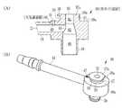
図1に示すように、内視鏡10は、例えば気管に挿入する気管支鏡であり、気管内に挿入される挿入部11と、挿入部11の後端部分に連設された操作部12と、図示しないプロセッサ装置や光源装置などに接続されるユニバーサルコード13とを備えている。 As shown in FIG. 1, an endoscope 10 is a bronchoscope that is inserted into a trachea, for example, and includes an
挿入部11には、鉗子等の処置具を挿入するための鉗子チャネル14が設けられている。この鉗子チャネル14の一端は、挿入部11の先端面に設けられた吸引/鉗子口(以下、単に吸引口という)15に接続し、他端は操作部12に設けられた鉗子入口16に接続している。この鉗子入口16は、処置具を挿入するとき以外は鉗子栓(図示せず)により閉塞されている。なお、鉗子入口16にシリンジ(図示せず)を接続し、このシリンジから生理食塩水等の洗浄水を注入した場合には、この洗浄水は鉗子チャネル14を通って吸引口15から噴出する。 The
また、挿入部の先端には、吸引口15の他に、観察窓や照明窓(図示せず)が設けられている。観察窓の奥には固体撮像素子(図示せず)などが取り付けられている。照明窓の奥には光ファイバケーブル(図示せず)が配置されている。固体撮像素子の信号線や光ファイバケーブルは、挿入部11やユニーバルコード13などを経て、上述のプロセッサ装置、光源装置にそれぞれ接続される。 In addition to the
鉗子チャネル14は、吸引口15から血液等の体液や体内汚物等の固形物などを吸引するための経路として用いられる。操作部12内には、鉗子チャネル14から分岐した吸引通路17が設けられている。この吸引通路17は、操作部12に設けられた吸引ボタン18に接続している。 The forceps channel 14 is used as a path for sucking a body fluid such as blood or a solid matter such as filth from the
吸引ボタン18は、吸引通路17の他に操作部12外において、吸引ポンプ(負圧源)20に通じる負圧源通路21に接続している。吸引ボタン18は、押圧操作またはその押圧操作の解除により、吸引通路17と負圧源通路21との連通/遮断を切り替える。吸引ポンプ20は、内視鏡検査中は吸引を常時行う。 In addition to the suction passage 17, the
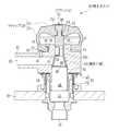
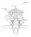
押圧解除時の状態を示す図2、及び押圧操作時の状態を示す図3において、吸引ボタン18は、大別して操作部12に固定されたシリンダユニット24と、このシリンダユニット24内に収容されたプランジャ25と、シリンダユニット24及びプランジャ25を連結するキャップ26とで構成される。 In FIG. 2 showing a state at the time of releasing the pressure and FIG. 3 showing a state at the time of the pressing operation, the
シリンダユニット24は、操作部12の筐体28に固定された略管状の弁ケーシング29と、この弁ケーシング29に連結された略管状の弁ガイド部材(シリンダ)30とで構成される。なお、以下の説明では、図中上方側を先端側、図中下方側を後端側という。 The
弁ケーシング29は、その先端部が筐体28の外側に突出し、その後端部が筐体28の内側に突出した状態で筐体28に固定されている。弁ケーシング29内には、その軸方向に長く延びた管路31が形成されている。弁ケーシング29の後端部には、吸引通路17に接続する吸引接続口32が設けられており、この吸引接続口32を介して管路31と吸引通路17とが連通する。また、管路31の先端側の開口には弁ガイド部材30が連結される。 The
弁ガイド部材30は、その後端部に設けられた略筒状の挿嵌部34が弁ケーシング29の先端側の開口に嵌合して連結されており、管路31と同心の管路を有している。弁ガイド部材30の先端部には、プランジャ25の軸先端部を突出させるためのシリンダ開口35(図4参照)が形成されている。 The
シリンダ先端の端面(以下、シリンダ端面という、図4参照)30a上には、キャップ26と連結する円筒部37が設けられている。円筒部37の先端面(以下、筒先端面という、図4参照)37aには上述のシリンダ開口35が開口している。円筒部37の先端の外周面にはフランジ38が形成されている。フランジ38には、その一部を平面状に切り欠かくことにより、キャップ26との回転止めに用いられる第1キャップ回転止め面38a(図4(B)参照、回転規制手段)が形成されている。また、フランジ38の底面と、円筒部37の外周面と、シリンダ端面30aとにより、キャップ26が連結する略環状のシリンダ用キャップ取付溝39(図4(A)参照)が形成されている。 A
図4(A)に示すように、弁ガイド部材30内には、管路31等を介して吸引通路17に接続し、管路31に対して平行に長く延びた第1管路40と、第1管路40の先端側で第1管路40と同軸に延び、先端が上述のシリンダ開口35として解放されるとともに、第1管路40よりも細径の第2管路41と、第2管路41の後端と第1管路40の先端を接続する略錐形状の第3管路42とが設けられている。 As shown in FIG. 4 (A), in the
図4(B)に示すように、弁ガイド部材30における第3管路42の側方に位置する部分には、負圧源通路21に接続する接続パイプ44が設けられている。この接続パイプ44は、第1〜第3管路40〜42に対して略直交する方向に長く延びており、負圧源通路21の一部を構成している。第3管路42の内壁には、接続パイプ44に通じる負圧源連通口45が開口している。 As shown in FIG. 4B, a
また、弁ガイド部材30には、その先端面におけるキャップ26と対向する部分に開口した先端面開口47と、接続パイプ44の内壁面に開口した内壁面開口48とを接続する大気連通路50が設けられている。これにより、大気連通路50を介して、負圧源通路21が大気と連通する。 Further, the
図2及び図3に戻って、プランジャ25は、弁ガイド部材30にその軸方向に移動自在に収容されており、押圧操作または押圧解除により、吸引通路17と負圧源通路21との連通/遮断を切り替える。このプランジャ25は、弁ガイド部材30の各管路40〜42の軸方向に長く延びた略円柱状の本体軸部52と、略錐形状の弁部(以下、錐形弁部という)53とが一体形成されてなる。本体軸部52は、第2管路41にその軸方向に移動自在に装着され、かつ軸先端部(押圧操作部)52aがシリンダ開口35から突出している。 2 and 3, the
軸先端部52aには、その外周にキャップ26を連結するための略環状のプランジャ用キャップ取付溝54が形成されている(図5(A),(B)参照)。また、この軸先端部52aのプランジャ用キャップ取付溝54よりも先端側部分には、その一部を平面状に切り欠かくことによって、キャップ26との回転止めに用いられる第2キャップ回転止め面55(図5(B)参照、回転規制手段)が形成されている。さらに、軸先端部52aの先端面は、押圧操作を受ける押圧操作面56となる。 A substantially annular plunger
錐形弁部53は、本体軸部52の軸後端部52bに設けられており、外周壁が第3管路42の内壁に沿う形状を有している。この錐形弁部53は、本体軸部52の移動に応じて第2管路41及び第3管路42内を移動する。 The
プランジャ25は、押圧解除時に、錐形弁部53が第3管路42の内壁に当接して負圧源連通口45を塞ぐことにより、負圧源通路21と吸引通路17との連通を遮断する遮断状態になる。また、プランジャ25は、その軸先端部52aが押圧操作によりシリンダ開口35内に所定量押し込まれたときに、錐形弁部53が第3管路42の内壁から離れて負圧源連通口45を開放することで、負圧源通路21と吸引通路17とを連通する連通状態になる。なお、ここでいう所定量とは、例えば、キャップ26が筒先端面37aに当接してさらなる押し込みが規制されるまでの押し込み量である。 When the
図5(A)、(B)に示すように、プランジャ25には、本体軸部52の側面に開口した側面開口58と、錐形弁部53の底面に開口した底面開口59とを連通する内部管路60が設けられている。側面開口58は、プランジャ25が連通状態にあるときに、負圧源連通口45の略前方に位置する本体軸部52の部分の外周面上に開口している。内部管路60は、プランジャ25が連通状態にあるときに、底面開口59に流入した各種体液や固形物を側面開口58へ案内する。この内部管路60の径は、本体軸部52内では一定であるが、錐形弁部53内では底面開口59に近づくのに従って次第に増加する。 As shown in FIGS. 5A and 5B, the
図6に示すように、錐形弁部53の最大外径d1は、第1管路40の内径d2よりも1回り小さく形成されている。プランジャ25を弁ガイド部材30内で移動させたときに、錐形弁部53が第1管路40の内壁と摺動することが防止される。なお、本体軸部52は、その直径が第2管路41の内径よりも僅かに小さく形成されており、第2管路41によりガイドされる。 As shown in FIG. 6, the maximum outer diameter d <b> 1 of the
図2及び図3に戻って、キャップ26は、例えばゴムなどの弾性材料で形成されている。キャップ26は、軸先端部52aの先端に連結される略円板状の蓋部62と、蓋部62、軸先端部52a、及び弁ガイド部材30の先端部を囲む略筒形状を有し、弁ガイド部材30の先端部に連結されるスカート部63とが一体形成されてなる。 2 and 3, the
図7に示すように、蓋部62には、その中心にプランジャ25が貫通する貫通穴65が形成されている。貫通穴65は、蓋部62の上面に開口しており、軸先端部52aの先端(プランジャ用キャップ取付溝54よりも先端側)が嵌合する嵌合穴66と、この嵌合穴66の底面と蓋部62の底面を貫通し、軸先端部52aにおけるプランジャ用キャップ取付溝54の形成部分が挿通する挿通穴67が形成されている。 As shown in FIG. 7, a through
嵌合穴66の側壁面には、軸先端部52aの第2キャップ回転止め面55に当接する略平面状のプランジャ回転止め面(回転規制手段)69が形成されている。これにより、プランジャ25とキャップ26とが回転規制される。また、蓋部62における、挿通穴67の内壁を構成する第1環状凸部70は、軸先端部52aのプランジャ用キャップ取付溝54に嵌合する。これにより、蓋部62と軸先端部52aとが連結する。 A substantially planar plunger rotation stop surface (rotation restricting means) 69 that abuts against the second cap rotation stop
スカート部63は、その先端部が蓋部62の外周と一体化しており、後端部にはその内側に向かって突出した第2環状凸部71が設けられている。第2環状凸部71は、シリンダ用キャップ取付溝39に嵌合する。これにより、キャップ26と弁ガイド部材30とが連結する。また、第2環状凸部71のシリンダ端面30aに対向する対向面71aは、その先端面開口47に対向する部分が、プランジャ25からその径方向に遠ざかるのに従い次第にシリンダ端面30aから離れるような傾斜面71bに形成されている。この傾斜面71bは、本発明の大気連通制御手段として機能する(図2及び図3参照)。 The front end portion of the
第2環状凸部71の上面には、その開口周縁部を切り欠くことにより、フランジ38が嵌合するフランジ嵌合穴72が形成されている。このフランジ嵌合穴72の内壁には、フランジ38の第1キャップ回転止め面38aに当接する略平面状のガイド部材回転止め面(回転規制手段)73が形成されている。これにより、弁ガイド部材30とキャップ26とが回転規制される。さらに、このキャップ26を介して、弁ガイド部材30とプランジャ25とが間接的に回転規制される。これら両者の間接的な回転規制により、プランジャ25が連通状態に切り替えられたときに、その側面開口58を負圧源連通口45に略対向させることができる。 A flange
図2及び図3に戻って、キャップ26は、プランジャ25をシリンダ開口35の上方向に向けて付勢することで、このプランジャ25を遮断状態で維持する。また、キャップ26は、押圧操作により軸先端部52aがシリンダ開口35内に押し込まれたときに、蓋部62がシリンダ開口35に向けて移動し、さらにこの移動に伴いスカート部63がプランジャ25の径方向に拡径するとともにその軸方向に収縮(以下、適宜弾性変形という)する。さらに、キャップ26は、押圧操作が解除されたときに、スカート部63の弾性復元力により、元の形状に復元する。 2 and 3, the
スカート部63は、上述の弾性変形時に、その第2環状凸部71がシリンダ端面30aに向けて押圧される。これにより、傾斜面71bが先端面開口47に圧接することにより大気連通路50を閉塞する(図3参照)。また、スカート部63は、元の形状に復元したときに、その傾斜面71bが先端面開口47から離れることにより、大気連通路50を開放して負圧源通路21を大気と連通させる(図2参照)。 When the
次に、上記構成の吸引ボタン18の作用について説明を行う。内視鏡検査時には、吸引ポンプ20による吸引が常時行われる。このとき、吸引を行わない通常時においては、図8(A)に示すように、キャップ26によりプランジャ25が遮断状態で維持されるので、錐形弁部53の外周壁が第3管路42の内壁に押し付けられた状態となる。錐形弁部53の外周壁は第3管路42の錐形の内壁にフィットする形状であるので、この外周壁は負圧源連通口45の周縁に隙間なく密着する(図中、点線で表示)。 Next, the operation of the
特にこれら外周壁と内壁を錐形にした場合には、負圧源連通口45の形成位置や開口形状の誤差、及びプランジャ25の多少のがたつきが発生した場合でも、外周壁のいずれかの部分で負圧源連通口45を塞ぐことができるので、負圧源連通口45が隙間なく遮断される。これにより、Oリング等のシール部材をプランジャ25の外周あるいは負圧源連通口45の周縁部に装着することなく、吸引通路17と負圧源通路21との連通を遮断して吸引口15からの吸引を停止させることができる。 In particular, when the outer peripheral wall and the inner wall are conical, even if an error in the position or opening shape of the negative pressure
また、プランジャ25が遮断状態のときは、スカート部63の傾斜面71bが先端面開口47に圧接しておらず両者の間には隙間が形成されているため、大気連通路50は開放されている。これにより、負圧源通路21が大気と連通するため、負圧源連通口45が錐形弁部53で塞がれている場合でも、吸引ポンプ20に負荷がかかることが防止される。 Further, when the
吸引を行う場合には、図8(B)に示すように、押圧操作面56が押圧操作されて、キャップ26の弾性力に抗して軸先端部52aがシリンダ開口35内に押し込まれるとともに、キャップ26のスカート部63が上述したような拡径・収縮する弾性変形して、蓋部62が筒先端面37aに当接する。これにより、プランジャ25が遮断状態から連通状態に切り替わり、錐形弁部53が第3管路42の内壁から離れることにより、負圧源連通口45が開放される。 When performing suction, as shown in FIG. 8B, the
また、スカート部63が弾性変形した際に、その傾斜面71bが先端面開口47に圧接することで、大気連通路50が閉塞される。これにより、負圧源通路21と大気との連通が遮断されて、負圧源通路21内の負圧吸引力が増加する。 Further, when the
負圧源連通口45が開放されると、負圧源通路21と吸引通路17とが連通することにより、吸引口15から各種体液や固形物(以下、吸引物という)が吸引される。吸引物は、吸引通路17、吸引接続口32、及び管路31を経て、図中の矢印で示すように、弁ガイド部材30の第1管路40内に流入した後、内部管路60内を通って負圧源連通口45に流入する。上述の図10で説明した従来例のように弁ガイド部材30の管路内壁とプランジャ25の外周との間の狭い隙間に吸引物の通路を設けることなく、プランジャ25内に可能な限り広い径の内部管路60を形成している。その結果、シリンダユニット24において吸引物が通る通路の径が広くなるので、大きい固形の吸引物でもシリンダユニット24内を通過することができる。負圧源連通口45内に流入した吸引物は、負圧源通路21を通って内視鏡10の外部へ吸引される。 When the negative pressure
吸引を停止する場合には、押圧操作面56に対する押圧操作が解除される。この押圧操作解除により、スカート部63が弾性復元力によって元の形状に復元するため、蓋部62及びプランジャ25が引き上げられる。これにより、プランジャ25が連通状態から遮断状態に切り替わるため、上述の図8(A)で説明したように、負圧源通路21と吸引通路17との連通が遮断されて、吸引口15からの吸引が停止される。 When stopping the suction, the pressing operation on the
以下、吸引を行う場合には押圧操作によりプランジャ25を連通状態に切り替え、逆に吸引を停止する場合には押圧操作を解除してプランジャ25を遮断状態に切り替える。この際に、錐形弁部53は、その最大外径d1が第1管路40の内径d2よりも小さく形成されているので、遮断状態時に第3管路42の内壁に押し付けられるものの、この遮断状態時以外では第2及び第3管路41,42の内壁に接しない。このため、プランジャ25が連通状態と遮断状態のいずれか一方から他方に切り替わる際に、錐形弁部53は第2及び第3管路41,42の内壁と摺動することなく移動する。 Hereinafter, when performing suction, the
これに対して比較例を示す図9(A),(B)において、吸引ボタン80は、シリンダユニット81の弁ガイド部材82内に形成された直管状の管路83に、略棒状のプランジャ84が移動自在に装着され、かつこのプランジャ84にその側面開口85と底面開口86とを連通する内部管路87が設けられている。なお、本発明の吸引ボタン18や前述の図10で説明した吸引ボタンと機能・構成上同一のものについては、同一符号を付してその説明は省略している。 On the other hand, in FIGS. 9A and 9B showing a comparative example, the
上記構成の吸引ボタン80は、プランジャ84が押圧操作されていないときに、管路83の内壁に開口した負圧源連通口88に対して側面開口85の位置がプランジャ軸方向上方にずれるものの、プランジャ84の直径は管路83の内径よりも小さく形成されているので、プランジャ84の外周面により負圧源連通口88を完全に塞ぐことはできない。さらに、鉗子入口16から洗浄水を注入した際に、この注入圧力が高いと、洗浄水が内部管路87を逆流して側面開口85から負圧源連通口88に漏れるおそれがある。このため、プランジャ84の外周面には、非押圧操作時において側面開口85と負圧源連通口88との間に位置する部分S(点線で表示)にもOリング等のシール部材を設ける必要があるが、シール部材が管路83の内壁と摺動するため摺動抵抗が発生する。その結果、押圧解除時にプランジャ84が遮断状態に戻らないといった作動不良が発生する。 The
このような比較例の吸引ボタン80に対して、本発明の吸引ボタン18では、錐形の第3管路42の内壁に錐形弁部53の外周壁を押し付けて負圧源連通口45を塞ぐ構成であるため、プランジャ25の外周にOリング等を装着する必要はなく、さらに、上述したようにプランジャ25が移動したときに錐形弁部53が第2及び第3管路41,42の内壁と摺動しない。このため、プランジャ25内に内部管路60を設けて吸引物が通る通路の径を広くした場合でも、プランジャ25とシリンダユニット24の管路内壁との摺動抵抗の発生を抑えることができる。 In contrast to the
上記実施形態では、キャップ26のスカート部63の弾性復元力により、プランジャ25を遮断状態で維持しているが、例えば、蓋部62とシリンダ端面30aとの間にコイルバネ等を装着して、このコイルバネの付勢力によりプランジャ25を遮断状態で維持してもよい。 In the above embodiment, the
上記実施形態では、シリンダユニット24を構成する弁ケーシング29と弁ガイド部材30とが別体であるが、これらが一体であってもよい。 In the above embodiment, the
上記実施形態では、気管に挿入する内視鏡10に設けられた吸引ボタン18を例に挙げて説明を行ったが、例えば大腸に挿入される大腸内視鏡等の各種内視鏡に設けられている吸引ON/OFF切替用の吸引ボタンにも本発明を適用することができる。 In the above embodiment, the
10 内視鏡
15 吸引口
17 吸引通路
18 吸引ボタン
20 吸引ポンプ
21 負圧源通路
24 シリンダユニット
25 プランジャ
26 キャップ
35 シリンダ開口
40 第1管路
41 第2管路
42 第3管路
45 負圧源連通口
52 本体軸部
53 錐形弁部
58 側面開口
59 底面開口
60 内部管路10
Claims (10)
Translated fromJapanese前記操作部に設けられたシリンダであって、後端側が前記吸引通路に通じている第1管路と、前記第1管路の先端側で当該第1管路と同軸に延び、前記第1管路よりも小径でかつ先端がシリンダ開口で開放された第2管路と、前記第1管路の先端及び第2管路の後端を接続する略錐形状の第3管路とを有するシリンダと、
前記第3管路に開口し、前記負圧源通路に連通する負圧源連通口と、
前記第2管路にその軸方向に移動自在に収容され、前記シリンダ開口から突出した軸先端部を有する本体軸部と、前記本体軸部の軸後端部に設けられ、前記第3管路の内壁に沿う略錐形状の弁部と、前記本体軸部の側面と前記弁部の底面を連通する内部管路とを有するプランジャとを備え、
前記プランジャは、前記軸先端部が押圧操作されていないときに、前記弁部が前記内壁に当接して前記負圧源連通口を塞いで前記負圧源通路と前記吸引通路との連通を遮断する遮断状態になり、押圧操作により前記軸先端部が前記シリンダ開口内に所定量押し込まれたときに、前記弁部が前記内壁から離れて前記負圧源連通口を開放するとともに、前記本体軸部の側面に開口した前記内部管路の側面開口が前記第3管路内に移動することで、前記内部管路を介して前記負圧源通路と前記吸引通路とを連通する連通状態になることを特徴とする内視鏡の吸引ボタン。A suction passage that is provided in the operation portion of the endoscope and communicates with a suction opening that opens at a distal end of the endoscope insertion portion and a negative pressure source passage that is connected to a negative pressure source are connected to each other, and the negative pressure source In the endoscope suction button for switching communication / blocking between the passage and the suction passage,
A cylinder provided in the operating portion, the first pipe line having a rear end side communicating with the suction passage, and the first pipe line extending coaxially with the first pipe line on the tip side; A second conduit having a smaller diameter than the conduit and having a tip opened by a cylinder opening; and a substantially conical third conduit connecting the tip of the first conduit and the rear end of the second conduit. A cylinder,
A negative pressure source communication port that opens to the third conduit and communicates with the negative pressure source passage;
A main body shaft portion that is housed in the second pipe passage so as to be movable in the axial direction and has a shaft tip protruding from the cylinder opening; and a shaft rear end portion of the main body shaft portion, and the third pipe passage A substantially cone-shaped valve portion along the inner wall of the main body, and a plunger having a side surface of the main body shaft portion and an inner conduit communicating with the bottom surface of the valve portion,
When the shaft tip is not pressed, the plunger contacts the inner wall and closes the negative pressure source communication port to block communication between the negative pressure source passage and the suction passage. When the shaft tip is pushed into the cylinder opening by a predetermined amount by a pressing operation, the valve portion is separated from the inner wall to open the negative pressure source communication port, and the body shaft When the side opening of the internal pipe that is open on the side of the part moves into the third pipe, the negative pressure source passage and the suction passage are communicated with each other through the internal pipe. Endoscope suction button characterized by that.
前記遮断状態の前記プランジャの前記軸先端部を、前記付勢手段に抗して前記所定量だけ前記シリンダ開口に押し込むことにより、当該プランジャが前記連通状態に切り替わることを特徴とする請求項2記載の内視鏡の吸引ボタン。Biasing means for maintaining the plunger in the shut-off state;
3. The plunger is switched to the communication state by pushing the shaft tip portion of the plunger in the shut-off state into the cylinder opening by the predetermined amount against the biasing means. Endoscope suction button.
前記シリンダに設けられ、前記プランジャが前記遮断状態のときは前記大気連通路を開放するとともに、前記プランジャが前記連通状態のときは前記大気連通路を閉塞する大気連通制御手段とを備えることを特徴とする請求項1ないし7いずれか1項記載の内視鏡の吸引ボタン。An atmospheric communication path formed in the cylinder and communicating the negative pressure source path and the atmosphere;
And an atmospheric communication control means provided in the cylinder for opening the atmospheric communication passage when the plunger is in the shut-off state and closing the atmospheric communication passage when the plunger is in the communication state. The suction button for an endoscope according to any one of claims 1 to 7.
Priority Applications (4)
| Application Number | Priority Date | Filing Date | Title |
|---|---|---|---|
| JP2010211857AJP5404569B2 (en) | 2010-09-22 | 2010-09-22 | Endoscope suction button |
| EP11181994AEP2433550A1 (en) | 2010-09-22 | 2011-09-20 | Suction button assembly for endoscope |
| CN201110281519.8ACN102406497B (en) | 2010-09-22 | 2011-09-21 | The attraction button assembly of endoscope |
| US13/238,044US20120071843A1 (en) | 2010-09-22 | 2011-09-21 | Suction button assembly for endoscope |
Applications Claiming Priority (1)
| Application Number | Priority Date | Filing Date | Title |
|---|---|---|---|
| JP2010211857AJP5404569B2 (en) | 2010-09-22 | 2010-09-22 | Endoscope suction button |
Publications (2)
| Publication Number | Publication Date |
|---|---|
| JP2012065765Atrue JP2012065765A (en) | 2012-04-05 |
| JP5404569B2 JP5404569B2 (en) | 2014-02-05 |
Family
ID=44674515
Family Applications (1)
| Application Number | Title | Priority Date | Filing Date |
|---|---|---|---|
| JP2010211857AExpired - Fee RelatedJP5404569B2 (en) | 2010-09-22 | 2010-09-22 | Endoscope suction button |
Country Status (4)
| Country | Link |
|---|---|
| US (1) | US20120071843A1 (en) |
| EP (1) | EP2433550A1 (en) |
| JP (1) | JP5404569B2 (en) |
| CN (1) | CN102406497B (en) |
Cited By (2)
| Publication number | Priority date | Publication date | Assignee | Title |
|---|---|---|---|---|
| JP2015104425A (en)* | 2013-11-28 | 2015-06-08 | 富士フイルム株式会社 | Endoscope duct switching device and endoscope |
| CN115350381A (en)* | 2014-04-18 | 2022-11-18 | 贝克顿·迪金森公司 | Valve assembly, valve actuator and conduit assembly |
Families Citing this family (19)
| Publication number | Priority date | Publication date | Assignee | Title |
|---|---|---|---|---|
| US8275471B2 (en)* | 2009-11-06 | 2012-09-25 | Adura Technologies, Inc. | Sensor interface for wireless control |
| JP5678238B2 (en)* | 2012-11-21 | 2015-02-25 | オリンパスメディカルシステムズ株式会社 | Endoscope flow path switching valve unit and endoscope |
| US9161680B2 (en) | 2013-11-26 | 2015-10-20 | Bracco Diagnostics Inc. | Disposable air/water valve for an endoscopic device |
| DE102014103508B4 (en)* | 2014-03-14 | 2019-04-18 | Fresenius Medical Care Deutschland Gmbh | Tensioned valve for medical functional device, and medical functional device |
| EP3119468B1 (en)* | 2014-03-19 | 2019-01-09 | Fresenius Kabi Deutschland GmbH | Valve device with elastically pretensioned closure element for a medical system |
| DE102014113472A1 (en)* | 2014-09-18 | 2016-04-07 | Karl Storz Gmbh & Co. Kg | Insufflation and irrigation valve and endoscope with an insufflation and irrigation valve |
| CN104922742B (en)* | 2015-07-03 | 2018-04-27 | 重庆医科大学附属第一医院 | Through sheath endoscopic stone extraction technique vacuum suction regulating device |
| CN106667421B (en)* | 2015-11-10 | 2019-11-01 | 深圳开立生物医疗科技股份有限公司 | A kind of fluid channel valve, fluid channel switching valve and endoscope |
| JP2018121923A (en)* | 2017-02-01 | 2018-08-09 | オリンパス株式会社 | Air/water supply valve for endoscope and endoscope |
| AU2020311423B2 (en) | 2019-07-11 | 2023-01-19 | Boston Scientific Scimed, Inc. | Endoscope air/water flush adaptor and method |
| WO2021101954A1 (en) | 2019-11-18 | 2021-05-27 | United States Endoscopy Group, Inc. | Eus valve assemblies |
| US20210378486A1 (en)* | 2020-06-05 | 2021-12-09 | Ga Health Company Limited | Suction valve for an endoscope |
| AU2021353426B2 (en)* | 2020-09-29 | 2024-08-08 | Boston Scientific Scimed, Inc. | Reuse prevention for single-use valves for medical devices |
| CN215874570U (en)* | 2021-03-31 | 2022-02-22 | 浙江优亿医疗器械股份有限公司 | Anti-drop suction assembly |
| CN216366110U (en)* | 2021-10-28 | 2022-04-26 | 湖南省华芯医疗器械有限公司 | Suction button, suction valve assembly and endoscope |
| CN114099802A (en)* | 2021-11-24 | 2022-03-01 | 南微医学科技股份有限公司 | Operating device of lavage drainage catheter and lavage drainage device |
| CN115486795B (en)* | 2022-11-22 | 2023-05-23 | 浙江华诺康科技有限公司 | Endoscope handle and suction valve |
| CN116687314A (en)* | 2023-04-28 | 2023-09-05 | 浙江华诺康科技有限公司 | Suction valve and endoscope |
| CN116616678B (en)* | 2023-07-25 | 2023-10-20 | 湖南省华芯医疗器械有限公司 | Suction valve, endoscope handle and endoscope |
Citations (1)
| Publication number | Priority date | Publication date | Assignee | Title |
|---|---|---|---|---|
| JPS58133229A (en)* | 1982-02-02 | 1983-08-08 | オリンパス光学工業株式会社 | Suction change-over valve of endoscope |
Family Cites Families (8)
| Publication number | Priority date | Publication date | Assignee | Title |
|---|---|---|---|---|
| JPH01160525A (en)* | 1987-12-17 | 1989-06-23 | Olympus Optical Co Ltd | Endoscope |
| JP2004166944A (en) | 2002-11-20 | 2004-06-17 | Pentax Corp | Cylinder piston mechanism and cylinder piston mechanism of endoscope |
| JP2006055447A (en)* | 2004-08-20 | 2006-03-02 | Pentax Corp | Endoscope operation buttons and endoscope |
| JP4783155B2 (en) | 2006-01-12 | 2011-09-28 | 富士フイルム株式会社 | Endoscope suction control device |
| JP4841278B2 (en) | 2006-03-23 | 2011-12-21 | 富士フイルム株式会社 | Endoscope suction device |
| JP2008228990A (en) | 2007-03-20 | 2008-10-02 | Fujinon Corp | Suction device of endoscope |
| EP2095757A1 (en)* | 2008-02-26 | 2009-09-02 | FUJIFILM Corporation | Endoscopic aspiration device |
| CN101574555A (en)* | 2008-05-07 | 2009-11-11 | 张景平 | Medical manual automatic control secondary filter valve |
- 2010
- 2010-09-22JPJP2010211857Apatent/JP5404569B2/ennot_activeExpired - Fee Related
- 2011
- 2011-09-20EPEP11181994Apatent/EP2433550A1/ennot_activeWithdrawn
- 2011-09-21USUS13/238,044patent/US20120071843A1/ennot_activeAbandoned
- 2011-09-21CNCN201110281519.8Apatent/CN102406497B/ennot_activeExpired - Fee Related
Patent Citations (1)
| Publication number | Priority date | Publication date | Assignee | Title |
|---|---|---|---|---|
| JPS58133229A (en)* | 1982-02-02 | 1983-08-08 | オリンパス光学工業株式会社 | Suction change-over valve of endoscope |
Cited By (2)
| Publication number | Priority date | Publication date | Assignee | Title |
|---|---|---|---|---|
| JP2015104425A (en)* | 2013-11-28 | 2015-06-08 | 富士フイルム株式会社 | Endoscope duct switching device and endoscope |
| CN115350381A (en)* | 2014-04-18 | 2022-11-18 | 贝克顿·迪金森公司 | Valve assembly, valve actuator and conduit assembly |
Also Published As
| Publication number | Publication date |
|---|---|
| JP5404569B2 (en) | 2014-02-05 |
| US20120071843A1 (en) | 2012-03-22 |
| CN102406497B (en) | 2015-09-16 |
| EP2433550A1 (en) | 2012-03-28 |
| CN102406497A (en) | 2012-04-11 |
Similar Documents
| Publication | Publication Date | Title |
|---|---|---|
| JP5404569B2 (en) | Endoscope suction button | |
| JP5409570B2 (en) | Endoscope suction button | |
| JP5602712B2 (en) | Endoscope suction line switching device | |
| JP5552014B2 (en) | Endoscope suction button | |
| JP4783155B2 (en) | Endoscope suction control device | |
| JP4608606B2 (en) | Endoscope fluid control system | |
| US9615724B2 (en) | Fluid control apparatus for endoscope | |
| JP5349561B2 (en) | Endoscope switching device | |
| JP5546283B2 (en) | Endoscope suction line device | |
| CN112074224B (en) | Fluid control device for endoscope | |
| CN116456885A (en) | Endoscope with suction valve with retaining ring | |
| JP2012075473A (en) | Suction button of endoscope | |
| JP5409569B2 (en) | Endoscope suction button | |
| JP2012071021A (en) | Suction button of endoscope | |
| JP2008228990A (en) | Suction device of endoscope | |
| JP7119134B2 (en) | Suction control device for endoscope and endoscope | |
| JP5460542B2 (en) | Endoscope suction button | |
| JP2006000525A (en) | Ultrasound endoscope suction valve device | |
| JP4512427B2 (en) | Ultrasound endoscope suction valve device | |
| JP2014097231A (en) | Ultrasonic endoscope | |
| JP5197082B2 (en) | Endoscope suction device | |
| CN119564135A (en) | Endoscope including suction valve | |
| JP4217487B2 (en) | Endoscope pipe switching device | |
| JP6066681B2 (en) | Ultrasound endoscope | |
| CN119303171A (en) | Negative pressure suction system and assembly method thereof |
Legal Events
| Date | Code | Title | Description |
|---|---|---|---|
| A621 | Written request for application examination | Free format text:JAPANESE INTERMEDIATE CODE: A621 Effective date:20130108 | |
| A977 | Report on retrieval | Free format text:JAPANESE INTERMEDIATE CODE: A971007 Effective date:20130930 | |
| TRDD | Decision of grant or rejection written | ||
| A01 | Written decision to grant a patent or to grant a registration (utility model) | Free format text:JAPANESE INTERMEDIATE CODE: A01 Effective date:20131009 | |
| A61 | First payment of annual fees (during grant procedure) | Free format text:JAPANESE INTERMEDIATE CODE: A61 Effective date:20131029 | |
| R150 | Certificate of patent or registration of utility model | Ref document number:5404569 Country of ref document:JP Free format text:JAPANESE INTERMEDIATE CODE: R150 | |
| R250 | Receipt of annual fees | Free format text:JAPANESE INTERMEDIATE CODE: R250 | |
| R250 | Receipt of annual fees | Free format text:JAPANESE INTERMEDIATE CODE: R250 | |
| R250 | Receipt of annual fees | Free format text:JAPANESE INTERMEDIATE CODE: R250 | |
| R250 | Receipt of annual fees | Free format text:JAPANESE INTERMEDIATE CODE: R250 | |
| R250 | Receipt of annual fees | Free format text:JAPANESE INTERMEDIATE CODE: R250 | |
| LAPS | Cancellation because of no payment of annual fees |