JP2012063524A - Vehicular head-up display device - Google Patents
Vehicular head-up display deviceDownload PDFInfo
- Publication number
- JP2012063524A JP2012063524AJP2010206806AJP2010206806AJP2012063524AJP 2012063524 AJP2012063524 AJP 2012063524AJP 2010206806 AJP2010206806 AJP 2010206806AJP 2010206806 AJP2010206806 AJP 2010206806AJP 2012063524 AJP2012063524 AJP 2012063524A
- Authority
- JP
- Japan
- Prior art keywords
- light
- case body
- light source
- emitted
- display device
- Prior art date
- Legal status (The legal status is an assumption and is not a legal conclusion. Google has not performed a legal analysis and makes no representation as to the accuracy of the status listed.)
- Pending
Links
- 230000003287optical effectEffects0.000claimsabstractdescription38
- 238000001514detection methodMethods0.000description11
- 238000009792diffusion processMethods0.000description6
- 239000000758substrateSubstances0.000description4
- 238000000605extractionMethods0.000description3
- 239000011521glassSubstances0.000description3
- 239000000463materialSubstances0.000description3
- 230000004397blinkingEffects0.000description2
- 230000000903blocking effectEffects0.000description2
- 230000000694effectsEffects0.000description2
- 230000002093peripheral effectEffects0.000description2
- 229920003002synthetic resinPolymers0.000description2
- 239000000057synthetic resinSubstances0.000description2
- 239000004925Acrylic resinSubstances0.000description1
- 229920000178Acrylic resinPolymers0.000description1
- 239000000853adhesiveSubstances0.000description1
- 230000001070adhesive effectEffects0.000description1
- 238000010586diagramMethods0.000description1
- 239000000446fuelSubstances0.000description1
- 238000005286illuminationMethods0.000description1
- 238000004519manufacturing processMethods0.000description1
- 238000007639printingMethods0.000description1
- 230000001681protective effectEffects0.000description1
- 230000005855radiationEffects0.000description1
- 238000007650screen-printingMethods0.000description1
Images


Landscapes
- Instrument Panels (AREA)
Abstract
Description
Translated fromJapanese本発明は、発光体から発せられる出射光を反射部材である車両のフロントガラスにて反射させ、この反射によって得られた虚像を車両の利用者に視認させる車両用ヘッドアップディスプレイ装置に関するものである。 The present invention relates to a vehicle head-up display device that reflects emitted light emitted from a light emitter on a windshield of a vehicle, which is a reflection member, and allows a vehicle user to visually recognize a virtual image obtained by the reflection. .
従来より、この種の車両用ヘッドアップディスプレイ装置にあっては、例えば下記特許文献1に記載されているものが知られている。この特許文献1に記載の車両用ヘッドアップディスプレイ装置は、車両のインストルメントパネル(以下、インパネと言う)内部に取り付けられており、配線板上に車幅方向に沿い列状に実装された複数個の点光源と、配線板及び各点光源を収容する略箱型形状のケース体とを有し、ケース体は、各点光源が実装された配線板を搭置してなる底壁部と、この底壁部に対向する前面壁部と、この前面壁部と底壁部とを繋ぐ側壁部とから構成され、点光源からの出射光をケース体の前面壁部に設けられた透光性カバー(透光部)を介してケース体の外部へと出射させるとともに車両のフロントガラス(反射部材)にて反射させ、この反射によって得られたドット情報のごとき表示像(虚像)を運転者(車両の利用者)に視認させるものである。 2. Description of the Related Art Conventionally, as this type of vehicle head-up display device, for example, one described in Patent Document 1 below is known. The vehicle head-up display device described in Patent Document 1 is mounted inside an instrument panel (hereinafter referred to as an instrument panel) of a vehicle, and is mounted on a wiring board in a row along the vehicle width direction. Each point light source, a wiring board and a substantially box-shaped case body that accommodates each point light source, and the case body includes a bottom wall portion on which the wiring board on which each point light source is mounted is mounted. The translucent light is composed of a front wall portion facing the bottom wall portion and a side wall portion connecting the front wall portion and the bottom wall portion, and light emitted from the point light source is provided on the front wall portion of the case body. The display image (virtual image) such as dot information obtained by this reflection is emitted to the outside of the case body through the protective cover (translucent portion) and reflected by the windshield (reflecting member) of the vehicle. (Vehicle user) is visually recognized.
なお、この場合、車両用ヘッドアップディスプレイ装置は、マイクロコンピュータからなる制御部と、障害物(歩行者等)の位置データを制御部に出力するレーザレーダや、人体の有無を検出し、その検出結果を人体検出データとして制御部に出力する熱赤外線センサから構成された障害物検知部とを備えてなる。制御部は、障害物検知部から出力される前記位置データや前記人体検出データに基づいて、障害物の存在方向に対応する1つもしくは隣接する複数個の点光源を点灯動作させるべく、光源駆動回路に指令信号を出力する。 In this case, the vehicle head-up display device detects the presence or absence of a human body or a laser radar that outputs a control unit including a microcomputer and position data of an obstacle (such as a pedestrian) to the control unit. And an obstacle detection unit including a thermal infrared sensor that outputs the result as human body detection data to the control unit. The control unit drives the light source to turn on one or a plurality of adjacent point light sources corresponding to the direction of the obstacle based on the position data and the human body detection data output from the obstacle detection unit. A command signal is output to the circuit.
光源駆動回路は、前記指令信号を受けて障害物の存在方向に対応する1つもしくは複数個の点光源を駆動し、これにより障害物の存在方向に対応する1つもしくは複数個の点光源が点灯する。そして、この点光源の点灯に伴い、点光源から出射される出射光は、透光性カバーを通過した後、車両のフロントガラス(反射部材)によって運転者側に反射され、これにより運転者は前記虚像を視認することができる。ここでの虚像の表示は、運転者に対し速度の出し過ぎであることを注意喚起する注意喚起表示としての機能を有していることになる。 The light source driving circuit receives the command signal and drives one or more point light sources corresponding to the direction in which the obstacle exists, whereby one or more point light sources corresponding to the direction in which the obstacle exists. Light. As the point light source is turned on, the emitted light emitted from the point light source passes through the translucent cover and is then reflected by the windshield (reflecting member) of the vehicle toward the driver side. The virtual image can be visually recognized. The display of the virtual image here has a function as a warning display for calling attention to the driver that the speed is excessive.
ところで、点光源から発せられる出射光は、放射角(光照射領域角度)が大きく、様々な方向へ進む。従って、上述した特許文献1に記載の車両用ヘッドアップディスプレイ装置の場合、ケース体の底壁部側に配設された点光源からの出射光は、主に光源の光軸方向(つまり透光性カバー側)に向けて出射されるものの、その一部が光軸から離れた領域(つまりケース体の側壁部側)に向けて放射され、この光軸から離れた領域に向けて放射される出射光の一部が、迷光となってケース体における側壁部の内壁面にあたって反射し、ケース体の前面壁部に設けられた透光性カバーへと到達することがあった。 By the way, the emitted light emitted from the point light source has a large radiation angle (light irradiation region angle) and travels in various directions. Therefore, in the case of the vehicle head-up display device described in Patent Document 1 described above, the emitted light from the point light source disposed on the bottom wall portion side of the case body is mainly in the optical axis direction of the light source (that is, translucent light). Is emitted toward the area away from the optical axis (that is, toward the side wall of the case body), and is emitted toward the area away from the optical axis. Some of the emitted light becomes stray light and is reflected on the inner wall surface of the side wall portion of the case body, and sometimes reaches the translucent cover provided on the front wall portion of the case body.
そして、このようにケース体における側壁部の内壁面を経て透光性カバーへと到達してなる出射光の一部(前記迷光)が、透光性カバーから出射されフロントガラスに映し出されることで、運転者は、本来、表示されるべき表示像の他に、前記迷光の発生により本来、表示されるべきでなない不要な像(所謂、ゴースト像)を視認することになる。つまり、前記迷光によって生じる像は、運転者にとって本来表示されるべきではない不要な像であり、かかる不要な像が発生することで表示像の表示品質が低下してしまうという問題点があり、この点で更なる改良の余地が残されていた。
そこで本発明は、前述の課題に対して対処するため、不要な像の発生を抑制し、表示品質を向上させることが可能な車両用ヘッドアップディスプレイ装置の提供を目的とするものである。A part of the emitted light (the stray light) that reaches the translucent cover through the inner wall surface of the side wall portion of the case body in this way is emitted from the translucent cover and projected on the windshield. The driver visually recognizes an unnecessary image (so-called ghost image) that should not be displayed originally due to the generation of the stray light in addition to the display image that should be displayed. That is, the image generated by the stray light is an unnecessary image that should not be displayed for the driver, and there is a problem that the display quality of the display image deteriorates due to the generation of such an unnecessary image. There was room for further improvement in this regard.
SUMMARY OF THE INVENTION Accordingly, an object of the present invention is to provide a vehicle head-up display device that can suppress generation of an unnecessary image and improve display quality in order to cope with the above-described problems.
本発明は、光源と、前記光源を収容するケース体とを有し、前記光源からの出射光を前記ケース体に設けられた透光部を介して前記ケース体の外部へと出射させるとともに所定の反射部材にて反射させ、この反射によって得られた虚像を車両の利用者に視認させる車両用ヘッドアップディスプレイ装置において、前記ケース体には、前記光源の光軸から離れた領域に向けて放射される前記出射光の一部が前記ケース体の内壁部を経て前記反射部材に到達するのを防ぐ遮光部が形成されてなることを特徴とする。 The present invention includes a light source and a case body that accommodates the light source, and emits light emitted from the light source to the outside of the case body via a translucent portion provided in the case body. In the vehicle head-up display device for reflecting the virtual image obtained by this reflection to the user of the vehicle, the case body radiates toward the region away from the optical axis of the light source. A light shielding portion is formed to prevent a part of the emitted light from reaching the reflecting member via the inner wall portion of the case body.
また本発明は、前記遮光部は、前記内壁部の内側に突出形成された壁部からなることを特徴とする。 In the invention, it is preferable that the light-shielding portion includes a wall portion that protrudes from the inside of the inner wall portion.
また本発明は、光源と、前記光源を収容するケース体とを有し、前記光源からの出射光を前記ケース体に設けられた透光部を介して前記ケース体の外部へと出射させるとともに所定の反射部材にて反射させ、この反射によって得られた虚像を車両の利用者に視認させる車両用ヘッドアップディスプレイ装置において、前記光源の光軸から離れた領域に向けて放射される前記出射光の一部が前記ケース体の内壁部を経て前記反射部材に到達するのを防ぐ遮光部を前記ケース体とは別体にて形成し、前記遮光部と前記ケース体とを所定の固定手段を用いて固定してなることを特徴とする。 In addition, the present invention includes a light source and a case body that houses the light source, and emits light emitted from the light source to the outside of the case body through a light transmitting portion provided in the case body. In the vehicle head-up display device for reflecting the virtual image obtained by the reflection by a predetermined reflecting member and allowing the vehicle user to visually recognize the emitted light, the emitted light radiated toward a region away from the optical axis of the light source. Is formed separately from the case body to prevent a part of the light from passing through the inner wall of the case body and reaching the reflecting member, and the light shielding section and the case body are provided with predetermined fixing means. It is characterized by being fixed using.
また本発明は、前記遮光部は、前記内壁部と当接するように前記内壁部の内側に配設された壁部からなることを特徴とする。 In the invention, it is preferable that the light shielding portion is a wall portion disposed inside the inner wall portion so as to be in contact with the inner wall portion.
また本発明は、光源と、前記光源を収容するケース体とを有し、前記光源からの出射光を前記ケース体に設けられた透光部を介して前記ケース体の外部へと出射させるとともに所定の反射部材にて反射させ、この反射によって得られた虚像を車両の利用者に視認させる車両用ヘッドアップディスプレイ装置において、前記透光部には、前記光源の光軸から離れた領域に向けて放射される前記出射光の一部が前記ケース体の内壁部を経て前記反射部材に到達するのを防ぐ遮光部が形成されてなることを特徴とする。 In addition, the present invention includes a light source and a case body that houses the light source, and emits light emitted from the light source to the outside of the case body through a light transmitting portion provided in the case body. In a vehicle head-up display device in which a virtual image obtained by reflection by a predetermined reflecting member is visually recognized by a vehicle user, the translucent portion is directed toward a region away from the optical axis of the light source. A light-shielding portion is formed to prevent a part of the emitted light radiated from reaching the reflecting member through an inner wall portion of the case body.
また本発明は、前記遮光部は、前記透光部の周縁に設けられた遮光層からなることを特徴とする。 In the invention, it is preferable that the light shielding portion includes a light shielding layer provided at a periphery of the light transmitting portion.
本発明によれば、初期の目的を達成でき、不要な像の発生を抑制し、表示品質を向上させることが可能な車両用ヘッドアップディスプレイ装置を提供できる。 ADVANTAGE OF THE INVENTION According to this invention, the initial purpose can be achieved, the generation | occurrence | production of an unnecessary image can be suppressed, and the head-up display apparatus for vehicles which can improve display quality can be provided.
(第1実施形態)以下、図1〜図4に基づいて、本発明を車両用のヘッドアップディスプレイ装置に適用した一実施形態を説明する。(First Embodiment) An embodiment in which the present invention is applied to a head-up display device for a vehicle will be described below with reference to FIGS.
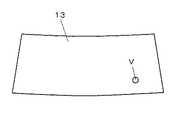
車両用ヘッドアップディスプレイ装置は、図1に示すように車両10のインパネ11内部に配設された発光装置12が出射する出射光Lを反射部材である車両10のフロントガラス13で車両10の運転者(利用者)14の方向に反射させ、虚像Vの表示を行うものである。換言すれば、車両用ヘッドアップディスプレイ装置は、発光装置12に備えられる後述する光源から発せられる出射光Lをフロントガラス13(前記反射部材)に出射し、この出射によって得られた虚像Vを運転者14に視認させるものである。これにより運転者14は、運転席の正面前方に表示される虚像Vを風景と重畳させて観察することができる。 As shown in FIG. 1, the vehicle head-up display device operates the
発光装置12は、図2に詳しく示すように、回路基板20と、この回路基板20上に実装(配設)された光源30と、発光装置12の外装ケースを構成するケース体40とから主に構成されている。 As shown in detail in FIG. 2, the
回路基板20は、例えば所定の配線パターンが施された硬質回路基板からなり、前記配線パターン上に光源30が搭載されている。かかる回路基板20は、ケース体40の後述する底壁部上に載置されている。 The
光源30は、例えば赤色光を発するチップ型発光ダイオードからなり、ケース体40に設けられる後述するカバーに向けて照明光(出射光L)を供給する発光体である。なお、この場合、光源30は、その光照射領域角度が光軸31を中心として左右にそれぞれ略60度の指向性を持つものが採用されている。このことは、光源30は、その光照射領域角度が略120度であることを意味している。 The
ケース体40は、例えば黒色の遮光性合成樹脂材料からなり、略箱型形状に形成され、回路基板20を搭置する載置部としての底壁部41と、この底壁部41の前方側に位置する前面壁部42と、底壁部41と前面壁部42とを繋ぐ略枠状の側壁部43とを有し、底壁部41と前面壁部42と側壁部43とで囲まれるケース体40の内部空間である空間部44(つまりケース体40内)に回路基板20や光源30が収容されている。 The
そして、ケース体40における前面壁部42の略中央部には、略矩形状の開口窓からなる開口部42aが開口形成され、かかる開口部42aには、開口部42aを塞ぐように透光部である透光性カバー45が配設されている。 An opening 42a made up of a substantially rectangular opening window is formed at a substantially central portion of the
このケース体40に設けられた透光性カバー45は、透光性の合成樹脂材料(例えばアクリル樹脂)からなり、所定の曲率を有する曲面形状(湾曲形状)の曲面部45aと、この曲面部45aを取り囲むように曲面部45aの周囲に位置する鍔形状のフランジ部45bとが一体形成された構成となっており、光源30から発せられる出射光Lが透過(通過)する光透過性部材としての機能を有している。 The
また、この場合、曲面部45aは、例えば太陽光(外光)が、曲面部45aにあたって反射したときに、この反射光がフロントガラス13を介して運転者14側に反射されないような前記曲率を有するように曲面部45aの曲面形状が設定されているものとする。つまり、このことは、曲面部45aは、外光を受けた際に反射する前記反射光がフロントガラス13を通じて運転者14側に反射されないような曲面形状にて形成されることを意味している。 Further, in this case, the
なお、前面壁部42には、その下端側において、透光性カバー45のフランジ部45bを保持するように、開口部42a(つまり前面壁部42の内壁面)から内方に向けて突出形成された鍔形状からなる保持部42bが設けられ、この保持部42bによってフランジ部45bが保持されることで、透光性カバー45は開口部42aを塞ぐように開口部42aに配設される構成となっている。 The
また、46は、側壁部43の中央部よりやや上方に位置する側壁部43箇所の内壁面(内壁部)43aから内方に向けて突出形成された略枠状の突出壁部からなる遮光部である。この内壁面43aの内方(内側)に突出形成された突出壁部(壁部)である遮光部46は、光源30の光軸31から離れた領域に向けて放射される出射光Lの一部Mが、ケース体40における側壁部43の略中央部に位置する内壁面43a箇所を経て透光性カバー45(フロントカバー13)に到達するのを防ぐ光遮蔽部材としての機能を有している。
従って、本例のように光照射領域角度(指向性)が120度の光源30を採用した場合において、光源30の光軸31から離れた領域に向けて放射される出射光Lの一部Mは、側壁部43の略中央部に位置する内壁面43aにあたって反射し、迷光となって透光性カバー45側に進むことになるが、この透光性カバー45側に進む前記迷光(つまり出射光Lの一部M)は、ケース体40に一体形成された遮光部46によって遮られる構成となる。 Therefore, when the
なお、この遮光部46は、出射光Lの進行方向と交わるように内壁面43aから内方に向けて延びる突出壁部として設けると、内壁面43aで反射して透光性カバー45側に向かう光の進行を効果的に遮断することができる。この場合、遮光部46と底壁部41との間には、遮光部46による遮蔽空間が形成される。光源30からの光の照射範囲を制限するだけであれば、光源30の周囲を光の出射方向に開口する筒状部材で覆うことも考えられるが、単に筒状部材で覆うだけでは筒状部材の内壁面で反射した光が透光性カバー45側に向かう虞がある。 In addition, if this light-shielding
かかる構成によれば、透光性カバー45を通過(透過)する光源30からの出射光Lは、光源30の光軸31及びその付近(近傍)から出射され、略枠状の遮光部46の中央領域に形成された窓部47を通過する光(つまり正規の光路からの光)のみとなるため、従来のように光源の光軸から離れた領域に向けて放射される光(つまり正規の光路以外からの光)が、ケース体における側壁部の内壁面を経て、迷光となって透光性カバー(フロントガラス)に到達することで生じていた不要な像(ゴースト像)の発生が防止される。 According to this configuration, the emitted light L from the
なお、必要に応じて、透光性カバー45を通じてケース体40内に入射する太陽光(外光)を拡散させるための図示省略した拡散シート(拡散手段)を、透光性カバー45と光源30との間に設けてもよい。 If necessary, a diffusion sheet (diffusion means) (not shown) for diffusing sunlight (external light) incident on the
例えば、前記拡散シートは、透光性カバー45の背面に貼り付けるか、あるいは窓部47を塞ぐように遮光部46上に載置(配置)すればよい。このように前記拡散シートを透光性カバー45の背面に設ける(あるいは前記拡散シートを窓部47を塞ぐように遮光部46上に載置する)ことで、透光性カバー45を経てケース体40内へと入射する外光の一部が、前記拡散シートによって拡散(乱反射)され、ケース体40内に収容されている光源30等の内機部品を積極的に照らさない構成となるため、外光による内機部品のフロントガラス13への映り込みを防止することが可能となる。 For example, the diffusion sheet may be attached to the back surface of the
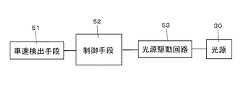
以上の各部により、発光装置12が構成されている。次に、本実施形態における車両用ヘッドアップディスプレイ装置の電気的構成を図3を用いて説明する。図3中、51は車速検出手段、52は制御手段、53は光源駆動回路、30は光源である。 The
車速検出手段51は、車両の速度を検出するための車速センサからなり、車両の運転状態に応じた車速検出信号を検出し制御手段52に出力するものである。 The vehicle speed detection means 51 is composed of a vehicle speed sensor for detecting the speed of the vehicle, detects a vehicle speed detection signal corresponding to the driving state of the vehicle, and outputs it to the control means 52.
制御手段52は、処理動作のプログラムが記憶されたROMや演算値を一時的に記憶するRAM、前記プログラムを実行するためのCPU等を有するマイクロコンピュータからなり、この場合、発光装置12内(空間部44)に配設固定された図示しない配線基板に実装されている。 The control means 52 is composed of a ROM that stores a program for processing operation, a RAM that temporarily stores calculation values, a microcomputer that has a CPU for executing the program, and the like. And mounted on a wiring board (not shown) disposed and fixed to the portion 44).
かかる制御手段52は、車速検出手段51からの車速検出信号に基づいて、光源30の動作を制御する指令信号を出力する。具体的には、光源30の点灯制御は、前記車速検出信号に基づいて以下の通り行われる。すなわち、本例の場合、制御手段52は、車両の運転状態に応じて入力される前記車速検出信号の値が所定の閾値(例えば時速100キロメートル)を超えたときのみ、光源30を点灯動作させるべく指令信号を出力する。 The
制御手段52の出力する指令信号は、光源30を駆動する光源駆動回路53へと入力される。光源駆動回路53は、この指令信号を受けて光源30を駆動し、これにより光源30が点灯する。 The command signal output from the control means 52 is input to the light
このように車速が時速100キロメートルを超えて光源30が点灯すると、光源30から発せられる出射光Lは、前述したように光軸31及び光軸31付近から出射された光(上述の正規の光路からの光)だけが、窓部47並びに透光性カバー45を介してケース体40の外部へと出射され、光源30の光軸31から離れた領域に向けて放射された光(正規の光路以外からの光)は、遮光部46によって遮られるため、透光性カバー45を通じてケース体40の外部には出射されないようになっている。 Thus, when the
そして、窓部47並びに透光性カバー45を介してケース体40の外部へと出射される光源30からの出射光L(正規の光路からの光)は、フロントガラス13側に出射され、さらにフロントガラス13にて運転者14側に反射される。運転者14は、この反射によって得られたゴースト像のない略ドット状の赤色発光像(虚像V)を視認することができる(図4参照)。かかる虚像Vは、運転者14に対し速度の出し過ぎを注意喚起する注意喚起表示としての機能を有していることになる。 And the emitted light L (light from the regular optical path) from the
以上のように本実施形態では、光源30と、この光源30を収容するケース体40とを有し、光源30からの出射光Lをケース体40に設けられた透光部である透光性カバー45を介してケース体40の外部へと出射させるとともにフロントガラス13にて反射させ、この反射によって得られた虚像Vを運転者14に視認させる車両用ヘッドアップディスプレイ装置において、ケース体40には、光源30の光軸31から離れた領域に向けて放射される出射光Lの一部Mがケース体40における側壁部43の内壁面(内壁部)43aを経て透光性カバー45(フロントガラス13)に到達するのを防ぐ遮光部46が形成されているものである。また遮光部46は、内壁面43の内側に突出形成された壁部からなるものである。 As described above, in the present embodiment, the
従って、透光性カバー45を通過する光源30からの出射光Lは、光源30の光軸31及び光軸31付近から出射され、窓部47を通過する光(正規の光路からの光)のみとなる。このため、従来のように光源の光軸から離れた領域に向けて放射される出射光の一部が迷光となってケース体における側壁部の内壁面を経て透光性カバー(フロントガラス)に到達することにより生じていた不要な像の発生が防止され、これにより運転者14は、ゴースト像のない虚像Vを視認可能となり、表示品質の向上した車両用ヘッドアップディスプレイ装置を提供することができる。 Therefore, the emitted light L from the
(第2実施形態)次に、本発明の第2実施形態を図5に基づいて説明するが、前述の第1実施形態と同一もしくは相当個所には同一の符号を用いてその詳細な説明は省略する。この第2実施形態が前記第1実施形態と異なる点は、前記第1実施形態にて採用した遮光部46に相当する遮光体60をケース体40とは別部材(別体)にて形成し、この遮光体(遮光部)60とケース体40とを所定の固定手段であるネジSを用いて固定した点である。なお、この場合、遮光体60の外周面は、側壁部43の内壁面43aに当接していることは言うまでもない。(Second Embodiment) Next, a second embodiment of the present invention will be described with reference to FIG. 5. The same reference numerals are used for the same or corresponding parts as in the first embodiment, and the detailed description thereof is as follows. Omitted. The second embodiment is different from the first embodiment in that a
本第2実施形態の場合、側壁部43の中央部よりやや上方には、ネジSのネジ部が貫通する一対のネジ孔43bが形成されているとともに、略枠状に形成された遮光体60の周縁部には、一対のネジ孔43bに対応する位置に凹部形状からなる一対のネジ螺合部61が設けられている。 In the case of the second embodiment, a pair of screw holes 43b through which the screw portion of the screw S passes is formed slightly above the central portion of the
そして、遮光体60とケース体40との固定は、まず各ネジ孔43bが各ネジ螺合部61にそれぞれ連通するように空間部44に略枠状の遮光体60を配設し、その後、ネジSのネジ部を側壁部43の外側からネジ孔43bに各々貫通させ、各ネジ孔43bを貫通してなるネジSのネジ部の所要部が、ネジ螺合部61にそれぞれ螺合されることで完了する。これにより遮光体60は、内壁面43aと当接するように内壁面43aの内側に固定(配設)されることになる。 Then, the
かかる第2実施形態においても、透光性カバー45を通過する光源30からの出射光Lは、光軸31及び光軸31付近から出射され、略枠状の遮光体60の中央領域に形成された窓部62を通過する光のみとなり、光源30の光軸31から離れた領域に向けて放射される光は、遮光部である遮光体60によって遮られて透光性カバー45(フロントガラス13)には到達しない構成となるため、運転者14はゴースト像のない虚像Vを視認することができ、前記第1実施形態と同様の作用効果を得ることができる。 Also in the second embodiment, the emitted light L from the
また本第2実施形態では、遮光体60とケース体40とがネジSを用いて固定されている例について説明したが、例えば遮光体60とケース体40とをネジSではなく両面テープ等を用いて接着固定してもよい。この場合、遮光体60の前記外周面と側壁部43の内壁面43aとが両面テープによって接合されることで、遮光体60がケース体40に固定されることになる。 In the second embodiment, the example in which the
(第3実施形態)次に、本発明の第3実施形態を図6に基づいて説明するが、前述の第1、第2実施形態と同一もしくは相当個所には同一の符号を用いてその詳細な説明は省略する。この第3実施形態では、前記第1実施形態の構成を基本構成として、ケース体40に一体形成されていた遮光部46を廃止し、透光性カバー45の背面における所定箇所に、光源30の光軸31から離れた領域に向けて放射される出射光Lの一部Mがケース体40における内壁面43aを経てフロントガラス13に到達するのを防ぐ遮光層からなる遮光部48を形成した構成となっている。(Third Embodiment) Next, a third embodiment of the present invention will be described with reference to FIG. 6. The same reference numerals are used for the same or corresponding parts as in the first and second embodiments described above, and the details thereof are described. The detailed explanation is omitted. In the third embodiment, based on the configuration of the first embodiment, the
この場合、遮光部48は、透光性カバー45における背面側の略中央部領域を除く透光性カバー45の背面箇所(つまり透光性カバー45における背面側の周縁)に印刷形成された印刷層からなり、例えば黒色系インクによりスクリーン印刷等の手段を用いて印刷形成されている。このように透光性カバー45の背面に遮光層からなる遮光部48を形成すると、前述した透光性カバー45における背面側の略中央部領域には、遮光部48が形成されない抜き印刷部からなる抜き部49が設けられることになる。 In this case, the light-shielding
かかる第3実施形態においても、透光性カバー45を通過する光源30からの出射光Lは、光軸31及び光軸31付近から出射され、透光性カバー45における背面側の略中央部領域に形成された抜き部59を通過する光のみとなり、光源30の光軸31から離れた領域に向けて放射される光は、抜き部59を除く透光性カバー45の背面箇所に設けられた遮光部58によって遮られて透光性カバー45(フロントガラス13)には到達しない構成となるため、運転者14はゴースト像のない虚像Vを視認することができ、前記第1、第2実施形態と同様の作用効果を得ることができる。 Also in the third embodiment, the emitted light L from the
また本第3実施形態では、遮光層からなる遮光部58が、透光性カバー45における背面側の略中央部領域を除く透光性カバー45の背面箇所に形成されている例について説明したが、例えば透光性カバー45における表面側の略中央部領域を除く透光性カバー45の表面箇所に遮光部58を設けてもよいことは言うまでもない。 In the third embodiment, the example in which the light shielding portion 58 made of the light shielding layer is formed on the back surface portion of the
また前記各実施形態では、光源30の点灯に伴い赤色発光像である虚像Vを表示するものであったが、例えば光源30を点滅させることで、赤色発光像である虚像Vを点滅表示させるようにしてもよい。このように虚像Vを点滅表示させることで、運転者14に対する注意喚起力をより高めることができる。 In each of the above embodiments, the virtual image V, which is a red light emission image, is displayed as the
また前記各実施形態では、車速が前記閾値を超えたときに光源30が点灯することに伴い、略ドット状の赤色発光像である虚像Vが表示され、運転者14に対し注意を喚起する(警告を促す)例について説明したが、例えば燃料の残量が所定値以下となっているときや、自車両と前方を走行している他の車両との間の車間距離が所定距離以下となったときに虚像Vを表示(点滅表示)し、運転者14に対し注意を喚起する(警告を促す)構成であってもよい。 In each of the above embodiments, as the
また前記各実施形態では、光軸31及び光軸31付近から発せられる出射光Lが、ダイレクトに透光性カバー45に至る例について説明したが、例えば詳細図示は省略するが、光源30と遮光部46、60との間、もしくは光源30と遮光部58の形成された透光性カバー45との間に所定の表示意匠部(例えば円形の表示意匠部)を有する意匠パネル(表示部材)を配置してもよい。この場合、前記意匠パネルは、その母材となる略平板状の透光性基板と、窓部47、62(もしくは抜き部59)に対応するように透光性基板の表面に形成された前記表示意匠部と、この表示意匠部の背景を形成すべく、表示意匠部を除いた透光性基板の表面箇所に設けられた遮光性を有する背景部とから構成される。なお、表示意匠部及び背景部は透光性基板の背面に形成してもよいし、必要に応じて、光源30と前記意匠パネルとの間に光源30側が平坦形状でかつ前記意匠パネル側が凸形状となる平凸レンズ、あるいは光源30側並びに前記意匠パネル側がともに凸形状となる両凸レンズからなるレンズ部材を配置してもよい。 In each of the above-described embodiments, the example in which the emitted light L emitted from the
なお、前記各実施形態では、光源30から発せられる出射光Lが、フロントガラス13に出射される例について説明したが、例えばフロントガラス13に出射光Lを良好に運転者14方向に反射させるコンバイナフィルムを設けてもよいし、あるいはフロントガラス13とは別の専用の反射部材に出射光Lを出射する構成としてもよい。 In each of the embodiments described above, the example in which the emitted light L emitted from the
12 発光装置
13 フロントガラス(反射部材)
14 運転者(利用者)
20 回路基板
30 光源
31 光軸
40 ケース体
41 底壁部
42 前面壁部
42a 開口部
43 側壁部
43a 内壁面(内壁部)
44 空間部
45 透光性カバー(透光部)
45a 曲面部
45b フランジ部
46、48 遮光部
47、62 窓部
49 抜き部
60 遮光体(遮光部)
L 出射光
S ネジ(固定手段)
V 虚像12 Light-emitting
14 Driver (User)
DESCRIPTION OF
44
45a
L Outgoing light S Screw (fixing means)
V virtual image
Claims (6)
Translated fromJapanese前記光源からの出射光を前記ケース体に設けられた透光部を介して前記ケース体の外部へと出射させるとともに所定の反射部材にて反射させ、この反射によって得られた虚像を車両の利用者に視認させる車両用ヘッドアップディスプレイ装置において、
前記ケース体には、前記光源の光軸から離れた領域に向けて放射される前記出射光の一部が前記ケース体の内壁部を経て前記反射部材に到達するのを防ぐ遮光部が形成されてなることを特徴とする車両用ヘッドアップディスプレイ装置。A light source, and a case body that houses the light source,
The emitted light from the light source is emitted to the outside of the case body through a light transmitting portion provided in the case body and reflected by a predetermined reflecting member, and a virtual image obtained by this reflection is used by the vehicle. In a vehicle head-up display device to be visually recognized by a person,
The case body is formed with a light shielding portion that prevents a part of the emitted light radiated toward a region away from the optical axis of the light source from reaching the reflecting member through the inner wall portion of the case body. A head-up display device for a vehicle.
前記光源からの出射光を前記ケース体に設けられた透光部を介して前記ケース体の外部へと出射させるとともに所定の反射部材にて反射させ、この反射によって得られた虚像を車両の利用者に視認させる車両用ヘッドアップディスプレイ装置において、
前記光源の光軸から離れた領域に向けて放射される前記出射光の一部が前記ケース体の内壁部を経て前記反射部材に到達するのを防ぐ遮光部を前記ケース体とは別体にて形成し、
前記遮光部と前記ケース体とを所定の固定手段を用いて固定してなることを特徴とする車両用ヘッドアップディスプレイ装置。A light source, and a case body that houses the light source,
The emitted light from the light source is emitted to the outside of the case body through a light transmitting portion provided in the case body and reflected by a predetermined reflecting member, and a virtual image obtained by this reflection is used by the vehicle. In a vehicle head-up display device to be visually recognized by a person,
A light-shielding portion that prevents a part of the emitted light radiated toward a region away from the optical axis of the light source from reaching the reflecting member via the inner wall portion of the case body is separated from the case body. Formed,
A vehicle head-up display device, wherein the light shielding portion and the case body are fixed using a predetermined fixing means.
前記光源からの出射光を前記ケース体に設けられた透光部を介して前記ケース体の外部へと出射させるとともに所定の反射部材にて反射させ、この反射によって得られた虚像を車両の利用者に視認させる車両用ヘッドアップディスプレイ装置において、
前記透光部には、前記光源の光軸から離れた領域に向けて放射される前記出射光の一部が前記ケース体の内壁部を経て前記反射部材に到達するのを防ぐ遮光部が形成されてなることを特徴とする車両用ヘッドアップディスプレイ装置。A light source, and a case body that houses the light source,
The emitted light from the light source is emitted to the outside of the case body through a light transmitting portion provided in the case body and reflected by a predetermined reflecting member, and a virtual image obtained by this reflection is used by the vehicle. In a vehicle head-up display device to be visually recognized by a person,
The light-transmitting portion is formed with a light-shielding portion that prevents a part of the emitted light radiated toward a region away from the optical axis of the light source from reaching the reflecting member through the inner wall portion of the case body. A vehicle head-up display device.
Priority Applications (1)
| Application Number | Priority Date | Filing Date | Title |
|---|---|---|---|
| JP2010206806AJP2012063524A (en) | 2010-09-15 | 2010-09-15 | Vehicular head-up display device |
Applications Claiming Priority (1)
| Application Number | Priority Date | Filing Date | Title |
|---|---|---|---|
| JP2010206806AJP2012063524A (en) | 2010-09-15 | 2010-09-15 | Vehicular head-up display device |
Publications (1)
| Publication Number | Publication Date |
|---|---|
| JP2012063524Atrue JP2012063524A (en) | 2012-03-29 |
Family
ID=46059304
Family Applications (1)
| Application Number | Title | Priority Date | Filing Date |
|---|---|---|---|
| JP2010206806APendingJP2012063524A (en) | 2010-09-15 | 2010-09-15 | Vehicular head-up display device |
Country Status (1)
| Country | Link |
|---|---|
| JP (1) | JP2012063524A (en) |
Cited By (8)
| Publication number | Priority date | Publication date | Assignee | Title |
|---|---|---|---|---|
| US9075229B2 (en) | 2013-04-16 | 2015-07-07 | Hyundai Motor Company | Cover of head up display and housing including the cover |
| JP2016009155A (en)* | 2014-06-26 | 2016-01-18 | 日本精機株式会社 | Head-up display device |
| US9269007B2 (en) | 2013-06-14 | 2016-02-23 | Denso Corporation | In-vehicle display apparatus and program product |
| US9878667B2 (en) | 2013-06-14 | 2018-01-30 | Denso Corporation | In-vehicle display apparatus and program product |
| JP2018165782A (en)* | 2017-03-28 | 2018-10-25 | パナソニックIpマネジメント株式会社 | Display device, optical element, and moving body including display device |
| WO2019087615A1 (en)* | 2017-10-30 | 2019-05-09 | 株式会社デンソー | Virtual image display device |
| WO2019208422A1 (en)* | 2018-04-23 | 2019-10-31 | 日本精機株式会社 | Head-up display device and method for manufacturing same |
| JP2024001918A (en)* | 2022-06-23 | 2024-01-11 | 矢崎総業株式会社 | Vehicle display apparatus |
Citations (12)
| Publication number | Priority date | Publication date | Assignee | Title |
|---|---|---|---|---|
| JPS62275846A (en)* | 1986-05-23 | 1987-11-30 | Nissan Motor Co Ltd | Vehicle display device |
| JPH02201313A (en)* | 1988-11-30 | 1990-08-09 | Hughes Aircraft Co | Led array polarization image source and 0 degree hologram virtual image head up display system |
| JPH06144083A (en)* | 1992-11-06 | 1994-05-24 | Yazaki Corp | Vehicle display |
| JP2004017708A (en)* | 2002-06-13 | 2004-01-22 | Nippon Seiki Co Ltd | Display device |
| JP2005148658A (en)* | 2003-11-19 | 2005-06-09 | Nippon Seiki Co Ltd | Display device |
| JP2005202145A (en)* | 2004-01-15 | 2005-07-28 | Olympus Corp | On-vehicle head-up display, vehicle having the same, and manufacturing method of vehicle having the same |
| JP2005313733A (en)* | 2004-04-28 | 2005-11-10 | Nippon Seiki Co Ltd | Display device for vehicle |
| JP2005338325A (en)* | 2004-05-26 | 2005-12-08 | Nippon Seiki Co Ltd | Display apparatus |
| JP2006310367A (en)* | 2005-04-26 | 2006-11-09 | Nippon Seiki Co Ltd | LIGHTING DEVICE AND LIQUID CRYSTAL DISPLAY DEVICE HAVING THE LIGHTING DEVICE |
| JP2009067352A (en)* | 2007-09-18 | 2009-04-02 | Nippon Seiki Co Ltd | Head-up display device |
| JP2009075514A (en)* | 2007-09-25 | 2009-04-09 | Nippon Seiki Co Ltd | Headup display device |
| JP2010175574A (en)* | 2009-01-27 | 2010-08-12 | Nippon Seiki Co Ltd | Head-up display device |
- 2010
- 2010-09-15JPJP2010206806Apatent/JP2012063524A/enactivePending
Patent Citations (12)
| Publication number | Priority date | Publication date | Assignee | Title |
|---|---|---|---|---|
| JPS62275846A (en)* | 1986-05-23 | 1987-11-30 | Nissan Motor Co Ltd | Vehicle display device |
| JPH02201313A (en)* | 1988-11-30 | 1990-08-09 | Hughes Aircraft Co | Led array polarization image source and 0 degree hologram virtual image head up display system |
| JPH06144083A (en)* | 1992-11-06 | 1994-05-24 | Yazaki Corp | Vehicle display |
| JP2004017708A (en)* | 2002-06-13 | 2004-01-22 | Nippon Seiki Co Ltd | Display device |
| JP2005148658A (en)* | 2003-11-19 | 2005-06-09 | Nippon Seiki Co Ltd | Display device |
| JP2005202145A (en)* | 2004-01-15 | 2005-07-28 | Olympus Corp | On-vehicle head-up display, vehicle having the same, and manufacturing method of vehicle having the same |
| JP2005313733A (en)* | 2004-04-28 | 2005-11-10 | Nippon Seiki Co Ltd | Display device for vehicle |
| JP2005338325A (en)* | 2004-05-26 | 2005-12-08 | Nippon Seiki Co Ltd | Display apparatus |
| JP2006310367A (en)* | 2005-04-26 | 2006-11-09 | Nippon Seiki Co Ltd | LIGHTING DEVICE AND LIQUID CRYSTAL DISPLAY DEVICE HAVING THE LIGHTING DEVICE |
| JP2009067352A (en)* | 2007-09-18 | 2009-04-02 | Nippon Seiki Co Ltd | Head-up display device |
| JP2009075514A (en)* | 2007-09-25 | 2009-04-09 | Nippon Seiki Co Ltd | Headup display device |
| JP2010175574A (en)* | 2009-01-27 | 2010-08-12 | Nippon Seiki Co Ltd | Head-up display device |
Cited By (11)
| Publication number | Priority date | Publication date | Assignee | Title |
|---|---|---|---|---|
| US9075229B2 (en) | 2013-04-16 | 2015-07-07 | Hyundai Motor Company | Cover of head up display and housing including the cover |
| US9269007B2 (en) | 2013-06-14 | 2016-02-23 | Denso Corporation | In-vehicle display apparatus and program product |
| US9878667B2 (en) | 2013-06-14 | 2018-01-30 | Denso Corporation | In-vehicle display apparatus and program product |
| JP2016009155A (en)* | 2014-06-26 | 2016-01-18 | 日本精機株式会社 | Head-up display device |
| EP3163354A4 (en)* | 2014-06-26 | 2017-11-29 | Nippon Seiki Co., Ltd. | Head-up display device |
| JP2018165782A (en)* | 2017-03-28 | 2018-10-25 | パナソニックIpマネジメント株式会社 | Display device, optical element, and moving body including display device |
| WO2019087615A1 (en)* | 2017-10-30 | 2019-05-09 | 株式会社デンソー | Virtual image display device |
| WO2019208422A1 (en)* | 2018-04-23 | 2019-10-31 | 日本精機株式会社 | Head-up display device and method for manufacturing same |
| JPWO2019208422A1 (en)* | 2018-04-23 | 2021-06-24 | 日本精機株式会社 | Head-up display device and its manufacturing method |
| JP7222395B2 (en) | 2018-04-23 | 2023-02-15 | 日本精機株式会社 | Head-up display device and manufacturing method thereof |
| JP2024001918A (en)* | 2022-06-23 | 2024-01-11 | 矢崎総業株式会社 | Vehicle display apparatus |
Similar Documents
| Publication | Publication Date | Title |
|---|---|---|
| JP5919724B2 (en) | Head-up display device for vehicle | |
| KR101823180B1 (en) | Vehicular heads-up display device | |
| JP2012063524A (en) | Vehicular head-up display device | |
| CN104204903B (en) | Head-up display | |
| JP2012163705A (en) | Head-up display device | |
| JP2018129259A (en) | Lamp device | |
| JP2007108429A (en) | Display device and headup display device for vehicle equipped therewith | |
| CN110857054B (en) | Vehicle interior lighting device and roof module | |
| WO2020158602A1 (en) | Vehicle display device | |
| JP7658387B2 (en) | Notification Device | |
| JP6696174B2 (en) | Display device | |
| JP2020032825A (en) | Vehicle display device | |
| JP2016107731A (en) | Head-up display device | |
| JP7375814B2 (en) | Vehicle display device | |
| JP6885215B2 (en) | Display device | |
| JP6729768B2 (en) | Vehicle display device | |
| JP2014106635A (en) | Lighting fixture system for vehicle | |
| JP2007055430A (en) | Display device for vehicle | |
| JP2020083085A (en) | Display device for vehicle | |
| JP6930244B2 (en) | Display device | |
| CN110857053A (en) | Vehicle interior lighting device and roof module | |
| JP7424188B2 (en) | display device | |
| JP2016057589A (en) | Head-up display device | |
| JP6308666B2 (en) | Vehicle display device | |
| JP2020192898A (en) | Vehicle display device |
Legal Events
| Date | Code | Title | Description |
|---|---|---|---|
| A621 | Written request for application examination | Free format text:JAPANESE INTERMEDIATE CODE: A621 Effective date:20130809 | |
| A977 | Report on retrieval | Free format text:JAPANESE INTERMEDIATE CODE: A971007 Effective date:20131225 | |
| A131 | Notification of reasons for refusal | Free format text:JAPANESE INTERMEDIATE CODE: A131 Effective date:20140123 | |
| A521 | Request for written amendment filed | Free format text:JAPANESE INTERMEDIATE CODE: A523 Effective date:20140310 | |
| A131 | Notification of reasons for refusal | Free format text:JAPANESE INTERMEDIATE CODE: A131 Effective date:20140401 | |
| A02 | Decision of refusal | Free format text:JAPANESE INTERMEDIATE CODE: A02 Effective date:20140724 |