JP2012059329A - Magnetic recorder - Google Patents
Magnetic recorderDownload PDFInfo
- Publication number
- JP2012059329A JP2012059329AJP2010203603AJP2010203603AJP2012059329AJP 2012059329 AJP2012059329 AJP 2012059329AJP 2010203603 AJP2010203603 AJP 2010203603AJP 2010203603 AJP2010203603 AJP 2010203603AJP 2012059329 AJP2012059329 AJP 2012059329A
- Authority
- JP
- Japan
- Prior art keywords
- magnetic
- recording
- row
- magnetic dot
- dot
- Prior art date
- Legal status (The legal status is an assumption and is not a legal conclusion. Google has not performed a legal analysis and makes no representation as to the accuracy of the status listed.)
- Pending
Links
Images


Classifications
- G—PHYSICS
- G11—INFORMATION STORAGE
- G11B—INFORMATION STORAGE BASED ON RELATIVE MOVEMENT BETWEEN RECORD CARRIER AND TRANSDUCER
- G11B5/00—Recording by magnetisation or demagnetisation of a record carrier; Reproducing by magnetic means; Record carriers therefor
- G11B5/48—Disposition or mounting of heads or head supports relative to record carriers ; arrangements of heads, e.g. for scanning the record carrier to increase the relative speed
- G11B5/54—Disposition or mounting of heads or head supports relative to record carriers ; arrangements of heads, e.g. for scanning the record carrier to increase the relative speed with provision for moving the head into or out of its operative position or across tracks
- G11B5/55—Track change, selection or acquisition by displacement of the head
- G11B5/5521—Track change, selection or acquisition by displacement of the head across disk tracks
- G11B5/5526—Control therefor; circuits, track configurations or relative disposition of servo-information transducers and servo-information tracks for control thereof
- B—PERFORMING OPERATIONS; TRANSPORTING
- B82—NANOTECHNOLOGY
- B82Y—SPECIFIC USES OR APPLICATIONS OF NANOSTRUCTURES; MEASUREMENT OR ANALYSIS OF NANOSTRUCTURES; MANUFACTURE OR TREATMENT OF NANOSTRUCTURES
- B82Y10/00—Nanotechnology for information processing, storage or transmission, e.g. quantum computing or single electron logic
- G—PHYSICS
- G11—INFORMATION STORAGE
- G11B—INFORMATION STORAGE BASED ON RELATIVE MOVEMENT BETWEEN RECORD CARRIER AND TRANSDUCER
- G11B5/00—Recording by magnetisation or demagnetisation of a record carrier; Reproducing by magnetic means; Record carriers therefor
- G11B5/012—Recording on, or reproducing or erasing from, magnetic disks
- G—PHYSICS
- G11—INFORMATION STORAGE
- G11B—INFORMATION STORAGE BASED ON RELATIVE MOVEMENT BETWEEN RECORD CARRIER AND TRANSDUCER
- G11B5/00—Recording by magnetisation or demagnetisation of a record carrier; Reproducing by magnetic means; Record carriers therefor
- G11B5/74—Record carriers characterised by the form, e.g. sheet shaped to wrap around a drum
- G11B5/743—Patterned record carriers, wherein the magnetic recording layer is patterned into magnetic isolated data islands, e.g. discrete tracks
- G11B5/746—Bit Patterned record carriers, wherein each magnetic isolated data island corresponds to a bit
- G—PHYSICS
- G11—INFORMATION STORAGE
- G11B—INFORMATION STORAGE BASED ON RELATIVE MOVEMENT BETWEEN RECORD CARRIER AND TRANSDUCER
- G11B5/00—Recording by magnetisation or demagnetisation of a record carrier; Reproducing by magnetic means; Record carriers therefor
- G11B5/84—Processes or apparatus specially adapted for manufacturing record carriers
- G11B5/855—Coating only part of a support with a magnetic layer
Landscapes
- Engineering & Computer Science (AREA)
- Chemical & Material Sciences (AREA)
- Nanotechnology (AREA)
- Physics & Mathematics (AREA)
- Mathematical Physics (AREA)
- Theoretical Computer Science (AREA)
- Crystallography & Structural Chemistry (AREA)
- Magnetic Record Carriers (AREA)
- Recording Or Reproducing By Magnetic Means (AREA)
Abstract
Translated fromJapaneseDescription
Translated fromJapanese本発明の実施形態は磁気記録装置に関する。 Embodiments described herein relate generally to a magnetic recording apparatus.
パーソナルコンピュータ、ハードディスクレコーダ等の情報機器の高機能化・高速化に伴い、ユーザの取り扱う情報の量は近年ますます増大してきている。このため、情報記録装置の記録媒体の記録密度を高めることが切望されている。記録密度を高めるためには、記録媒体において記録の書き込み単位である1つの記録セルまたは記録マークの大きさを微小化することが必要である。しかし、従来の記録媒体においては、記録セルまたは記録マークの微小化は大きな困難に直面している。 As information devices such as personal computers and hard disk recorders become more sophisticated and faster, the amount of information handled by users has been increasing in recent years. For this reason, it is desired to increase the recording density of the recording medium of the information recording apparatus. In order to increase the recording density, it is necessary to reduce the size of one recording cell or recording mark which is a recording writing unit in the recording medium. However, in conventional recording media, miniaturization of recording cells or recording marks faces great difficulties.
現行のハードディスク装置の記録媒体は、ディスク基板上に厚さ数10nm程度のグラニュラー薄膜を堆積させた構造となっている。記録密度を高めるために、グラニュラー薄膜の粒子を細かくすると、熱揺らぎ(磁性体粒子の体積が小さくなると、熱エネルギーに比べて磁気エネルギーの比率が低下し、温度の影響で記録磁化が変化あるいは消失してしまう現象)のために、小さい多結晶体では記録が不安定となる。このため、記録セルが大きい場合は問題ないが、記録セルが小さくなると、記録の不安定性やノイズの増大が生じる。これは、記録セルに含まれる結晶粒の数が少なくなることと、記録セル間の相互作用が相対的に大きくなるためである。 The recording medium of the current hard disk device has a structure in which a granular thin film having a thickness of about several tens of nanometers is deposited on a disk substrate. If the granular thin film particles are made finer to increase the recording density, thermal fluctuation (when the volume of the magnetic particles is reduced, the ratio of magnetic energy is reduced compared to thermal energy, and the recording magnetization changes or disappears due to temperature. For this reason, recording is unstable with a small polycrystal. For this reason, there is no problem when the recording cell is large, but when the recording cell is small, recording instability and noise increase. This is because the number of crystal grains contained in the recording cell is reduced and the interaction between the recording cells is relatively increased.
これを回避するため、記録材料を非記録材料により予め分断し、単一の記録材料粒子を単一の記録セルとして記録再生を行うビットパターンドメディア(BPM)(単にパターンドメディアとも称する)が薄膜媒体に代わる次世代型磁気記録媒体として提案されている。 In order to avoid this, there is a bit patterned medium (BPM) (also simply referred to as a patterned medium) in which a recording material is divided in advance by a non-recording material and recording / reproduction is performed using a single recording material particle as a single recording cell. It has been proposed as a next-generation magnetic recording medium that replaces the thin film medium.
ビットパターンドメディアは、ナノメートルスケールの磁性ドットを基板上に規則配列させた磁性ドットアレイを含み、それぞれの磁性ドットの磁化の向きで“0”、“1”のデジタル信号(1ドットが1ビットに相当)が記録される。ビットパターンドメディアでは、各ビットが物理的に完全孤立しているため、連続膜媒体において高記録密度化の主たる阻害因子となる磁化転移に伴うノイズが原理的に生じない。 The bit patterned media includes a magnetic dot array in which nanometer-scale magnetic dots are regularly arranged on a substrate, and a digital signal of “0” or “1” (one dot is 1) depending on the magnetization direction of each magnetic dot. (Corresponding to a bit) is recorded. In bit-patterned media, each bit is physically completely isolated, so that in principle there is no noise associated with magnetization transition, which is a major obstacle to increasing the recording density in continuous film media.
しかし、記録材料が記録媒体表面において非記録材料により分断されているパターンドメディアでは、記録素子が記録媒体の特定位置にデータを記録する際に、分断された記録セルの1つ1つにデータを書き込む必要があるため、記録素子による記録開始のタイミング合わせが重要である。記録開始タイミングがずれると、記録素子が非記録材料部分または隣り合う記録セルにまたがって書き込み動作を行うことになるため、書き込みエラーが増えてしまう。 However, in a patterned medium in which the recording material is divided by a non-recording material on the surface of the recording medium, when the recording element records data at a specific position on the recording medium, the data is stored in each of the divided recording cells. Therefore, it is important to adjust the recording start timing by the recording element. When the recording start timing is deviated, the recording element performs a writing operation over the non-recording material portion or the adjacent recording cell, so that a writing error increases.
ビットパターンドメディアのドットの配列パターンには隣接するドット列とトラック方向にドット位置の位相の揃った格子(正方)パターンや当該位相をずらした千鳥パターンがある。 As dot arrangement patterns of bit patterned media, there are a lattice (square) pattern in which the dot positions are aligned in the track direction with the adjacent dot row, and a staggered pattern in which the phases are shifted.
ドットが縦横に整列している格子パターンでは、1行のドット列を1トラックとして記録・再生を行うため、ヘッドコア幅やトラッキング等のクロストラック方向の条件に精密な制約条件が要求される。 In a lattice pattern in which dots are aligned vertically and horizontally, recording / reproduction is performed with one row of dot columns as one track. Therefore, precise constraint conditions are required for conditions in the cross-track direction such as head core width and tracking.
一方、千鳥パターンでは、一定のドットピッチで配列された多数のドット列において、奇数行目のドット列と偶数行目のドット列とは位相が180°ずれている。記録・再生時に、たとえば隣接する2行のドット列をカバーする幅を有するヘッドを用い、2行のドット列を1データトラックとして記録・再生を行うと、ヘッドコア幅やトラッキング等のクロストラック方向の条件を緩和することができる。しかし、例えば千鳥パターンで2行のドット列を1データトラックとして記録する場合、1行のドット列周期の半分の周期で記録を行う必要がある為、ライト位相マージンが減少する。 On the other hand, in the staggered pattern, the phase of the odd-numbered dot rows and the even-numbered dot rows are shifted by 180 ° in a large number of dot rows arranged at a constant dot pitch. When recording / reproduction is performed using, for example, a head having a width that covers two adjacent dot rows, and recording / reproduction is performed using two dot rows as one data track, the cross-track direction such as head core width and tracking is performed. Conditions can be relaxed. However, when, for example, two dots are recorded as one data track in a staggered pattern, it is necessary to perform recording with a period that is half the period of one dot array, so that the write phase margin is reduced.
そこで、ライト位相マージンを拡大するために、ヘッドをクロストラック方向へ移動させながら1行のドット列に記録する、いわゆる瓦記録を行うことが考えられる。 Therefore, in order to enlarge the write phase margin, it is conceivable to perform so-called tile recording, in which recording is performed on one dot column while moving the head in the cross track direction.
しかし、上記のようにビットパターンドメディアについて磁性ドットの配置や記録方式を工夫したとしても、まだ記録時のフリンジ影響や再生時のクロストーク影響を改善する余地がある。 However, even if the arrangement of magnetic dots and the recording method are devised for the bit patterned medium as described above, there is still room for improving the fringe effect during recording and the crosstalk effect during reproduction.
ビットパターンド媒体を用い、記録時のフリンジ影響や再生時のクロストーク影響を改善できる磁気記録装置を提供する。 Provided is a magnetic recording device that uses a bit patterned medium and can improve the fringe effect during recording and the crosstalk effect during reproduction.
実施形態によれば、各々複数の磁性ドットを含む複数の磁性ドット列を含むデータ領域を有するビットパターンド媒体と、複数の磁性ドット列をカバーする幅を有する磁気ヘッドと、前記磁気ヘッドをクロストラック方向へ移動させるアクチュエータとを具備し、第n列の磁性ドット列に含まれる磁性ドットの保磁力が、第n+1列の磁性ドット列に含まれる磁性ドットの保磁力より大きい磁気記録装置が提供される。 According to the embodiment, a bit patterned medium having a data area including a plurality of magnetic dot arrays each including a plurality of magnetic dots, a magnetic head having a width covering the plurality of magnetic dot arrays, and the magnetic head are crossed. Provided with an actuator for moving in the track direction, and a magnetic recording device in which the coercivity of the magnetic dots contained in the nth magnetic dot row is greater than the coercivity of the magnetic dots contained in the (n + 1) th magnetic dot row is provided Is done.
以下、図面を参照して実施形態を詳細に説明する。 Hereinafter, embodiments will be described in detail with reference to the drawings.
図1は、実施形態に係る磁気記録装置の構成を説明するためのブロック図である。
ディスクドライブ1は、磁気記録媒体であるディスク10と、ディスク10を回転させるスピンドルモータ(SPM)11と、ヘッド12と、アクチュエータ13と、ヘッドアンプユニット(ヘッドIC)14とを有する。ディスク10は、ビットパターンド媒体である。ビットパターンド媒体は、ナノメートルスケールの磁性ドットが基板上に規則的に配列された磁性ドットアレイを含み、それぞれの磁性ドットの磁化の向きで“0”、“1”のデジタル信号(1ドットが1ビットに相当)が記録される。FIG. 1 is a block diagram for explaining the configuration of the magnetic recording apparatus according to the embodiment.
The
ヘッド12は、再生素子12Rと記録素子12Wとが、1つのスライダ上に分離して実装されている構造である。再生素子12Rは、ディスク10に記録されているデータを読出す。記録素子12Wは、ディスク10にデータを書き込む。アクチュエータ13は、ヘッド12を搭載しているサスペンション、アーム及びボイスコイルモータ(VCM)を有し、トラッキング制御のためにヘッド12をディスク10上の半径方向(クロストラック方向)に移動させる。 The
ヘッドアンプユニット14は、ヘッド12の再生素子12Rにより読出されたリード信号を増幅してリード/ライトチャネル15に出力するリードアンプを含む。また、ヘッドアンプユニット14は、リード/ライトチャネル15から出力されるライトデータをライト信号(ライト電流)に変換して、ヘッド12の記録素子12Wに供給するライトドライバを含む。 The
ディスクドライブ1は、プリント回路基板上に実装されたリード/ライトチャネル15、ハードディスクコントローラ(HDC)16、マイクロプロセッサ(CPU)17、メモリ18及びモータドライバ19を有する。なお、HDC16、CPU17、及びメモリ18は、ワンチップの集積回路20に実装されている。 The
リード/ライトチャネル15は、リード/ライトデータ信号を処理する信号処理ユニットである。HDC16は、ディスクドライブ1と図示しないホストシステム(パーソナルコンピュータやデジタル機器)とのインターフェースを構成し、データ転送制御やリード/ライト動作を制御する。CPU17は、ディスクドライブ1のメインコントローラであり、ヘッド位置決め制御(サーボ制御)や、リード/ライトデータの並べ替えを実行する。メモリ18は、フラッシュEEPROMである。 The read / write
モータドライバ19は、SPM11に駆動電流を供給するSPMドライバ及びアクチュエータ13のVCMに駆動電流を供給するVCMドライバを有する。VCMドライバは、CPU17のヘッド位置決め制御(サーボ制御)に応じてアクチュエータ13のVCMに駆動電流を供給して、ヘッド12をディスク10上の半径方向に移動制御する。 The
図2を参照して、実施形態に係る磁気記録装置に用いられるビットパターンド媒体の一例を説明する。図2は、ビットパターンド媒体の平面図である。 An example of a bit patterned medium used in the magnetic recording apparatus according to the embodiment will be described with reference to FIG. FIG. 2 is a plan view of the bit patterned medium.
実施形態のビットパターンド媒体の平面構造を一般化して記述すると以下の通りである。ディスクの周方向に沿って複数の磁性ドットが列をなして磁性ドット列を形成する。複数列(第1列から第t列まで、tは自然数)の磁性ドット列が1群をなしてサブ領域を形成する。複数群(第1群から第z群まで、zは自然数)のサブ領域がデータ領域を形成する。 A generalized description of the planar structure of the bit patterned medium of the embodiment is as follows. A plurality of magnetic dots form a row along the circumferential direction of the disk to form a magnetic dot row. A plurality of magnetic dot rows (from the first row to the t-th row, t is a natural number) form one group to form a sub-region. A sub-region of a plurality of groups (from the first group to the z-th group, z is a natural number) forms a data region.
ここで、瓦記録方式により記録が行われる場合を例としてビットパターンド媒体の平面構造をより詳細に説明する。1つのサブ領域内の任意の磁性ドット列を第n列、これに隣接し第n列より後に瓦記録が行われるドット列をn+1列という。また、任意のサブ領域を第q群、これに隣接し第q群より後に瓦記録が行われるサブ領域を第q+1群という。全ての磁性ドット列に通し番号をつける場合、任意の磁性ドット列の列番号は、式:t(q−1)+n(ここで、qは1からzまでの自然数、nは1からtまでの自然数である)で表される。実施形態においては、第n列の磁性ドット列に含まれる磁性ドットの保磁力が、第n+1列の磁性ドット列に含まれる磁性ドットの保磁力より大きくなっている。 Here, the planar structure of the bit patterned medium will be described in more detail by taking as an example a case where recording is performed by the shingled recording method. An arbitrary magnetic dot row in one sub-region is referred to as an nth row, and a dot row adjacent to this and subjected to shingled recording after the nth row is referred to as an n + 1 row. An arbitrary sub-area is referred to as a q-th group, and a sub-area adjacent to the q-th group and where tile recording is performed after the q-th group is referred to as a q + 1-th group. When serial numbers are assigned to all magnetic dot rows, the row number of an arbitrary magnetic dot row is expressed by the formula: t (q-1) + n (where q is a natural number from 1 to z, and n is from 1 to t). It is a natural number). In the embodiment, the coercivity of the magnetic dots included in the nth magnetic dot row is larger than the coercivity of the magnetic dots included in the (n + 1) th magnetic dot row.
図2では、第1列および第2列の2列(t=2)の磁性ドット列が1群をなして、第q群、第q+1群、第q+2群のサブ領域を形成している。図2では、第1列の磁性ドット列に含まれる磁性ドット31の保磁力が、第2列の磁性ドット列に含まれる磁性ドット32の保磁力より大きくなっている。 In FIG. 2, the magnetic dot rows of the first row and the second row (t = 2) form one group to form sub-regions of the q-th group, the q + 1-th group, and the q + 2-th group. In FIG. 2, the coercivity of the
実施形態において、磁気ヘッドの記録素子12Wは、複数の磁性ドット列をカバーする幅を有し、瓦記録方式により、第n列の磁性ドット列に記録した後、第n+1列の磁性ドット列に記録する。すなわち、アクチュエータにより記録素子12Wのクロストラック方向の端部(エッジ)が第n行の磁性ドット列をカバーするようにトラッキング制御して書き込みを行う。このとき、記録素子12Wは複数(たとえば3列)の磁性ドット列をカバーする幅を有するので、同じデータが第n+1行および第n+2行の磁性ドット列にも書き込まれる。次に、アクチュエータにより記録素子12Wを1ドット列分クロストラック方向へ移動させ、記録素子12Wのクロストラック方向の端部が第n+1行の磁性ドット列をカバーするようにトラッキング制御して書き込みを行う。次に、アクチュエータにより記録素子12Wを1ドット列分クロストラック方向へ移動させ、記録素子12Wのクロストラック方向の端部が第n+2行の磁性ドット列をカバーするようにトラッキング制御して書き込みを行う。瓦記録方式では、どの磁性ドット列でもドットピッチに対応したライト周波数で記録を行うので、ライト位相マージンが減少することはない。このため、ビットパターンド媒体の磁性ドットの配列精度や記録素子12Wの幅の精度を緩くすることができる。 In the embodiment, the
実施形態において、磁気ヘッドの再生素子12Rも、複数の磁性ドット列をカバーする幅を有し、たとえば第n列および第n+1列の磁性ドット列に含まれる磁性ドットを連続的に再生する。 In the embodiment, the reproducing
上記のように、第n列の磁性ドット列に含まれる磁性ドットの保磁力を、第n+1列の磁性ドット列に含まれる磁性ドットの保磁力より大きくすると、第n+1列の磁性ドット列に瓦記録しているときに、第n列の磁性ドット列へのフリンジ影響を抑えることができる。 As described above, if the coercive force of the magnetic dots included in the nth magnetic dot row is larger than the coercive force of the magnetic dots included in the (n + 1) th magnetic dot row, the magnetic dots in the (n + 1) th magnetic dot row are blocked. During recording, the influence of fringe on the nth magnetic dot row can be suppressed.
磁性ドットの保磁力の制御は、第n列の磁性ドット列に含まれる磁性ドットと第n+1列の磁性ドット列に含まれる磁性ドットとで厚みを同じにし、媒体面に平行な面における断面形状を変えることで可能となる。これは、後述するように、ビットパターンド媒体の製造方法を考慮すると、磁性ドットの形状を変える方法が容易であることによる。 The coercivity of the magnetic dots is controlled by making the magnetic dots contained in the nth magnetic dot row and the magnetic dots contained in the (n + 1) th magnetic dot row have the same thickness, and the cross-sectional shape in a plane parallel to the medium surface It is possible by changing This is because, as will be described later, in consideration of the manufacturing method of the bit patterned medium, it is easy to change the shape of the magnetic dots.
たとえば、図2に示すように、第n列の磁性ドット列に含まれる磁性ドットの断面形状の断面積を、第n+1列の磁性ドット列に含まれる磁性ドットに比べて小さくする。 For example, as shown in FIG. 2, the cross-sectional area of the cross-sectional shape of the magnetic dots included in the n-th magnetic dot row is made smaller than the magnetic dots included in the n + 1-th magnetic dot row.
ここで、互いに孤立した円形の磁性ドットパターンを配列したサンプルをKerr効果測定装置により測定して得られた保磁力について説明する。この場合、磁性ドットの直径を変化させた種々のサンプルについて測定を行った。図3は、円形状の磁性ドットの直径と保磁力との関係を示す図である。図3に示されるように、磁性ドットの直径が大きいほど、磁性ドットの保磁力は小さくなる。 Here, the coercive force obtained by measuring a sample in which circular magnetic dot patterns isolated from each other are measured with a Kerr effect measuring apparatus will be described. In this case, measurement was performed on various samples in which the diameter of the magnetic dots was changed. FIG. 3 is a diagram showing the relationship between the diameter of the circular magnetic dot and the coercive force. As shown in FIG. 3, the larger the magnetic dot diameter, the smaller the coercivity of the magnetic dot.
また、第n列の磁性ドット列に含まれる磁性ドットの断面形状の重心を通る最短の直線の長さを、第n+1列の磁性ドット列に含まれる磁性ドットに比べて短くしてもよい。磁性ドットの断面形状の重心を通る最短の直線の長さとは、たとえば磁性ドットの断面形状がトラック方向に短軸およびクロストラック方向に長軸をもつ楕円形状である場合、短径のことをいう。 Further, the length of the shortest straight line passing through the center of gravity of the cross-sectional shape of the magnetic dots included in the nth magnetic dot row may be shorter than that of the magnetic dots included in the n + 1th magnetic dot row. The length of the shortest straight line passing through the center of gravity of the cross-sectional shape of the magnetic dot means, for example, the short diameter when the cross-sectional shape of the magnetic dot is an elliptical shape having a minor axis in the track direction and a major axis in the cross-track direction. .
ここで、互いに孤立した楕円の磁性ドットパターンを配列したサンプルをKerr効果測定装置により測定して得られた保磁力について説明する。ここでは、楕円形状の磁性ドットの体積を直径12nmの円形ドットの体積に合わせ、楕円の短径および長径を変化させた種々のサンプルについて測定を行っている。図4は、楕円形状の磁性ドットの短径と保磁力との関係を示す図である。図4に示されるように、楕円形状の磁性ドットの短径が大きいほど、磁性ドットの保磁力は小さくなる。 Here, the coercive force obtained by measuring a sample in which elliptical magnetic dot patterns isolated from each other are measured by the Kerr effect measuring apparatus will be described. Here, the volume of the elliptical magnetic dot is matched to the volume of a circular dot having a diameter of 12 nm, and measurement is performed on various samples in which the minor axis and major axis of the ellipse are changed. FIG. 4 is a diagram showing the relationship between the minor axis of the elliptical magnetic dot and the coercive force. As shown in FIG. 4, the larger the minor axis of the elliptical magnetic dot, the smaller the coercivity of the magnetic dot.
次に、ビットパターンド媒体の製造方法を概略的に説明する。実施形態に係るビットパターンド媒体は、スタンパを用いたインプリント法により製造される。 Next, a method for manufacturing a bit patterned medium will be schematically described. The bit patterned medium according to the embodiment is manufactured by an imprint method using a stamper.
図5(a)〜(d)を参照してニッケルスタンパの製造方法を説明する。 A method for manufacturing a nickel stamper will be described with reference to FIGS.
図5(a)に示すように、基板51としてSiウエハーを用い、基板51上にレジスト溶液をスピンコートした後ベークしてレジスト層52を形成する。次に、電子ビーム描画装置を用い、基板51上のレジスト層52に所望のパターンを直接描画する。このとき、ビットパターンド媒体の磁性ドットの形状に対応させてパターンを描画する。次に、現像液に浸漬してレジストを現像し、レジスト原盤を作製する。 As shown in FIG. 5A, a Si wafer is used as the
図5(b)に示すように、レジスト原盤の表面にスパッタリングによってニッケルの導電化膜53を成膜する。図5(c)に示すように、導電化膜53を形成したレジスト原盤をスルファミン酸ニッケルメッキ浴に浸漬し、ニッケル電鋳して電鋳層54を形成する。図5(d)に示すように、レジスト原盤から電鋳層54および導電化膜53を剥離して、ビットパターンド媒体に対応する凹凸パターンが形成されたニッケルスタンパ55を得る。 As shown in FIG. 5B, a nickel conductive film 53 is formed on the surface of the resist master by sputtering. As shown in FIG. 5C, the resist original disk on which the conductive film 53 is formed is immersed in a nickel sulfamate plating bath and nickel electroformed to form an
次いで、図6(a)〜(h)を参照して、ニッケルスタンパを用いたビットパターンド媒体の製造方法を説明する。 Next, a method of manufacturing a bit patterned medium using a nickel stamper will be described with reference to FIGS.
図6(a)に示すように、ガラス基板71上に、厚さ120nmのCoZrNbからなる軟磁性下地層(図示せず)、厚さ20nmのRuからなる配向制御用の下地層(図示せず)、厚さ10nmのCo50Pt50からなる磁気記録層72、厚さ15nmのカーボンからなるエッチング保護層73を順次成膜する。ここでは、簡略化のために、軟磁性下地層および配向制御層は図示していない。As shown in FIG. 6A, on a
図6(b)に示すように、エッチング保護層73上に、レジスト74をスピンコートする。このレジスト74に対向するように、ビットパターンド媒体に対応する凹凸パターンが形成されたスタンパ55を配置する。 As shown in FIG. 6B, a resist 74 is spin-coated on the
図6(c)に示すように、スタンパ55を用いてインプリントを行い、スタンパ55の凹部に対応してレジスト74の凸部を形成する。インプリント後、スタンパ55を除去する。図6(d)に示すように、パターン化されたレジスト74の凹部の底に残っているレジスト残渣を除去する。図6(e)に示すように、レジスト74のパターンをマスクとして、エッチング保護層73をパターニングする。 As shown in FIG. 6C, imprinting is performed using the
図6(f)に示すように、エッチング保護層73のパターンをマスクとして、たとえばHe−N2混合ガスを用いたイオンビームエッチングを行い、磁気記録層72の一部をエッチングして凹凸を形成するとともに、凹部に残った磁気記録層72を改質して非磁性層75を形成する。As shown in FIG. 6F, by using the pattern of the etching
図6(g)に示すように、エッチング保護層73のパターンを除去する。このとき、エッチング保護層73のパターン上に残存するレジストもリフトオフされる。図6(h)に示すように、CVD(化学気相堆積法)によりカーボンからなる表面保護膜76を成膜する。表面保護膜76上に潤滑剤を塗布することにより実施形態に係るビットパターンド媒体を得る。 As shown in FIG. 6G, the pattern of the
上記のようにビットパターンド媒体の磁性ドットの形状制御は、図5(a)の電子線描画プロセスによって行われる。すなわち、磁性ドットに相当するパターンの形状を変えることにより、図6(f)の磁気記録層72の加工プロセスを経た後に、パターン形状が反映された磁性ドットを形成できる。ただし、パターンはエッチングマスクとして作用し、磁性ドットを構成する磁気記録層72の有無のみを決定する。このため、図5および図6に示した方法では、磁性ドットの組成や磁性ドット毎の厚さを制御することは不可能である。したがって、磁性ドットの保磁力を制御するには、媒体面に平行な面における断面形状を変える方法が容易である。 As described above, the shape control of the magnetic dots of the bit patterned medium is performed by the electron beam drawing process of FIG. That is, by changing the shape of the pattern corresponding to the magnetic dots, the magnetic dots reflecting the pattern shape can be formed after the processing process of the
実施形態においては、第n列の磁性ドット列に含まれる磁性ドットに記録するときの記録電流を、第n+1列の磁性ドット列に含まれる磁性ドットに記録するときの記録電流より大きくすることが好ましい。 In the embodiment, the recording current when recording on the magnetic dots included in the nth magnetic dot row may be larger than the recording current when recording on the magnetic dots included in the n + 1th magnetic dot row. preferable.
すなわち、保磁力の高い第n列の磁性ドット列に含まれる磁性ドットへの記録電流より、瓦記録で後から記録される第n+1列の磁性ドット列に含まれる磁性ドットへの記録電流を下げることで、後から記録する際の記録素子からの漏えい磁界を下げることができ、先に記録した磁性ドットの保磁力が高いことと相乗して、先に記録した磁性ドット列へのフリンジ影響を下げることができる。 That is, the recording current to the magnetic dots included in the (n + 1) th magnetic dot row recorded later by tile recording is lowered from the recording current to the magnetic dots included in the nth magnetic dot row having a high coercive force. Therefore, the leakage magnetic field from the recording element when recording later can be lowered, and in combination with the high coercivity of the previously recorded magnetic dots, the fringe effect on the previously recorded magnetic dot array can be reduced. Can be lowered.
図2を参照して説明したように、ビットパターンド媒体のデータ領域が、複数列の磁性ドット列を1群とする複数群のサブ領域を含む場合、異なるサブ領域に含まれ互いに隣接する磁性ドット列間の間隔を、同一のサブ領域に含まれ互いに隣接する磁性ドット列間の間隔よりも大きくするとともに、第q群のサブ領域の最後の磁性ドット列に含まれる磁性ドットの保磁力を、第q+1群のサブ領域の第1列の磁性ドット列に含まれる磁性ドットの保磁力よりも小さくすることが好ましい。 As described with reference to FIG. 2, when the data area of the bit patterned medium includes a plurality of groups of sub-areas each including a plurality of magnetic dot arrays, the magnetic areas included in different sub-areas and adjacent to each other The interval between dot rows is larger than the interval between adjacent magnetic dot rows included in the same sub-region, and the coercivity of the magnetic dots contained in the last magnetic dot row in the q-th sub-region is increased. It is preferable that the coercive force of the magnetic dots included in the first magnetic dot row of the q + 1th sub-region is smaller than the coercivity of the magnetic dots.
既述したように、第n列の磁性ドット列に含まれる磁性ドットの保磁力を第n+1列の磁性ドット列に含まれる磁性ドットの保磁力より大きくすると、フリンジ影響を抑えることができるので、互いに隣接する磁性ドット列間の間隔を狭くすることができる。 As described above, if the coercive force of the magnetic dots included in the nth magnetic dot row is larger than the coercive force of the magnetic dots included in the (n + 1) th magnetic dot row, the fringe effect can be suppressed. An interval between adjacent magnetic dot rows can be reduced.
一方、データ領域全体で瓦記録の順番に保磁力を徐々に変えることは、データ領域のトラック数が多いことから現実的ではない。そこで、複数列の磁性ドット列でサブ領域を形成し、複数群のサブ領域を形成し、1つのサブ領域内において第n列の磁性ドット列に含まれる磁性ドットの保磁力を、第n+1列の磁性ドット列に含まれる磁性ドットの保磁力より大きくし、複数のサブ領域にわたって保磁力の変化が周期性をもつようにすることが現実的である。このような配置では、第q群のサブ領域の最後の磁性ドット列に含まれる磁性ドットの保磁力が、第q+1群のサブ領域の第1列の磁性ドット列に含まれる磁性ドットの保磁力よりも小さくなる。この場合、第q群のサブ領域の最後の磁性ドット列と第q+1群のサブ領域の第1列の磁性ドット列との間の間隔を、同一のサブ領域に含まれ互いに隣接する磁性ドット列間の間隔よりも大きくして、フリンジ影響を抑えることが好ましい。 On the other hand, gradually changing the coercive force in the order of shingled recording in the entire data area is not realistic because the number of tracks in the data area is large. Therefore, a sub-region is formed by a plurality of magnetic dot rows, a plurality of groups of sub-regions are formed, and the coercive force of the magnetic dots included in the n-th magnetic dot row in one sub-region is set to the (n + 1) th row. It is realistic that the coercive force of the magnetic dots included in the magnetic dot row is larger than the coercive force so that the change of the coercive force has periodicity over a plurality of sub-regions. In such an arrangement, the coercivity of the magnetic dots included in the last magnetic dot row of the q-th sub-region is equal to the coercivity of the magnetic dots included in the first magnetic dot row of the q + 1-th sub-region. Smaller than. In this case, the interval between the last magnetic dot row in the q-th sub-region and the first magnetic dot row in the q + 1-th sub-region is included in the same sub-region and is adjacent to each other. It is preferable to suppress the fringe effect by setting the interval larger than the interval.
実施形態では、複数列の磁性ドット列に含まれる磁性ドットを1つの再生素子で連続的に再生することが好ましい。この場合、1つの再生素子で再生される複数の磁性ドット列間の間隔を狭めることができるので、上記のように第q群のサブ領域の最後の磁性ドット列と第q+1群のサブ領域の第1列の磁性ドット列との間の間隔を大きくしても、記録密度を保つことができ、同時に再生時のクロストークを低減させることができる。 In the embodiment, it is preferable that magnetic dots included in a plurality of magnetic dot rows are continuously reproduced by one reproducing element. In this case, since the interval between the plurality of magnetic dot rows reproduced by one reproducing element can be narrowed, the last magnetic dot row of the q-th group sub-region and the q + 1-th group of sub-regions as described above. Even if the interval between the first magnetic dot rows is increased, the recording density can be maintained, and at the same time, the crosstalk during reproduction can be reduced.
実施形態においては、1つの再生素子で連続的に再生される複数列の磁性ドット列のうち互いに隣接する磁性ドット列に含まれる磁性ドットが位相シフトしている、いわゆる千鳥配置でもよい。 In the embodiment, a so-called staggered arrangement in which magnetic dots included in adjacent magnetic dot rows among a plurality of magnetic dot rows continuously reproduced by one reproducing element are phase-shifted may be used.
この配置では、複数の磁性ドット列を連続的に再生する際に、各々の磁性ドット列に含まれる磁性ドットが順次再生されるため、各磁性ドット列の記録情報を別々に取得することができる。 In this arrangement, when a plurality of magnetic dot rows are continuously reproduced, the magnetic dots included in each magnetic dot row are sequentially reproduced, so that the recording information of each magnetic dot row can be acquired separately. .
別の実施形態においては、1つの再生素子で連続的に再生される複数列の磁性ドット列に含まれる磁性ドットを同位相で配置し、複数列の磁性ドット列に含まれる磁性ドットからの再生信号強度の合計に基づいて復号するようにしてもよい。 In another embodiment, magnetic dots included in a plurality of magnetic dot rows continuously reproduced by one reproducing element are arranged in the same phase, and reproduction from the magnetic dots included in the plurality of magnetic dot rows is performed. You may make it decode based on the sum total of signal strength.
このように、複数の磁性ドット列を同位相で記録再生すれば、各磁性ドット列を瓦記録することが不要となり、瓦記録方式では不可能であった再生トラック毎のランダム記録が可能になる。また、複数の磁性ドット列を同位相で再生するので、再生素子の幅を広くすることができ、再生素子の製造マージンが改善される。 As described above, if a plurality of magnetic dot rows are recorded and reproduced in the same phase, it is not necessary to perform shingled recording of each magnetic dot row, and random recording can be performed for each reproduction track, which is impossible with the shingled recording method. . In addition, since a plurality of magnetic dot rows are reproduced in the same phase, the width of the reproducing element can be widened, and the manufacturing margin of the reproducing element is improved.
実施形態においては、異なる磁性ドット列に含まれる磁性ドットの形状を変えるので、磁性ドット列毎に再生強度が異なることがある。図2では、断面積の小さい第n列(第1列)の磁性ドットからの再生信号強度は、断面積の大きい第n+1列(第2列)の磁性ドットからの再生信号強度より小さくなる。このような場合、図2に示すように、第1列および第2列の2列の磁性ドット列に含まれる磁性ドットを1つの再生素子12Rで連続的に再生するときに、再生素子12Rの中心を第1列の磁性ドット列と第2列の磁性ドット列との中間位置から、第1列の磁性ドット列に向かって距離δだけオフセットすることが好ましい。こうすれば、第1列の磁性ドット列からの再生信号強度が増大し、第2列の磁性ドット列からの再生信号強度が減少するため、両方の磁性ドット列からの再生信号強度を揃え、再生を容易にすることができる。 In the embodiment, since the shape of the magnetic dots included in different magnetic dot rows is changed, the reproduction intensity may be different for each magnetic dot row. In FIG. 2, the reproduction signal intensity from the magnetic dots in the nth column (first column) having a small cross-sectional area is smaller than the reproduction signal intensity from the magnetic dots in the (n + 1) th column (second column) having a large cross-sectional area. In such a case, as shown in FIG. 2, when the magnetic dots included in the two magnetic dot rows of the first row and the second row are continuously reproduced by one reproducing
図面を参照しながら実施例を説明する。 Embodiments will be described with reference to the drawings.
以下の参照例および実施例においては、強磁性膜として垂直記録に適した厚さ10nmのCo50Pt50合金を用い、強磁性膜を加工することによって種々の構造のビットパターンド媒体を作製した。In the following reference examples and examples, a Co50 Pt50 alloy having a thickness of 10 nm suitable for perpendicular recording was used as a ferromagnetic film, and bit patterned media having various structures were fabricated by processing the ferromagnetic film. .
記録素子および再生素子は、強磁性層にCoCrPt合金を用いた通常の垂直磁気記録媒体での記録再生に基づいて測定したところ、以下のような仕様を有していた。すなわち、浮上高2nm、記録電流(Iw)30mAで記録し、浮上高2nmで再生したときの測定結果から、記録素子の実効幅は100nm、再生素子の実効幅は40nmであった。 The recording element and reproducing element were measured based on recording / reproducing on a normal perpendicular magnetic recording medium using a CoCrPt alloy for the ferromagnetic layer, and had the following specifications. That is, from the measurement results when recording was performed at a flying height of 2 nm and a recording current (Iw) of 30 mA and reproduced at a flying height of 2 nm, the effective width of the recording element was 100 nm and the effective width of the reproducing element was 40 nm.
[参照例]
(媒体構造)
図7に示すように、ディスクの周方向に沿って複数の磁性ドット30が列をなして磁性ドット列を形成し、複数の磁性ドット列を含むデータ領域を有するビットパターンド媒体を作製した。[Reference example]
(Media structure)
As shown in FIG. 7, a plurality of magnetic dots 30 formed a row along the circumferential direction of the disk to form a magnetic dot row, and a bit patterned medium having a data region including the plurality of magnetic dot rows was produced.
磁性ドットの形状および磁性ドット列の配置は以下の通りである。磁性ドット列に含まれる磁性ドット30の媒体面に平行な面における断面形状を直径10nmの円形とした。1つの磁性ドット列内でドットピッチを20nmとした。隣接する2列の磁性ドット列に含まれる磁性ドットは、互いに位相が180度シフトする千鳥配置とした。隣接する2列の磁性ドット列間の間隔は20nmとした。このビットパターンド媒体のデータ領域における磁性ドットの密度は、1.6Tドット/inch2である。The shape of the magnetic dots and the arrangement of the magnetic dot rows are as follows. The cross-sectional shape of the magnetic dots 30 included in the magnetic dot row in a plane parallel to the medium surface was a circle having a diameter of 10 nm. The dot pitch was 20 nm in one magnetic dot row. The magnetic dots included in the two adjacent magnetic dot rows were arranged in a staggered manner in which the phases shifted from each other by 180 degrees. The interval between two adjacent magnetic dot rows was 20 nm. The density of magnetic dots in the data area of this bit patterned medium is 1.6 T dots / inch2 .
図3に示されるように、直径10nmの円形の磁性ドットの保磁力は5000Oeである。 As shown in FIG. 3, the coercivity of a circular magnetic dot having a diameter of 10 nm is 5000 Oe.
また、隣接する群の磁性ドット列の影響を避けるために、2列の磁性ドット列を残し、両側の磁性ドット列を除去して、孤立領域を形成した。 In order to avoid the influence of adjacent groups of magnetic dot rows, two magnetic dot rows were left and the magnetic dot rows on both sides were removed to form isolated regions.
(記録)
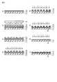
上述した仕様の記録素子の端部を用いて各磁性ドット列に対して浮上高2nm、記録電流Iw=30mAで瓦記録した。各磁性ドット列内において、隣接する磁性ドットのビットが交互に反転する101010…というパターンで記録した。(Record)
Using the end portion of the recording element having the above-described specifications, tile recording was performed on each magnetic dot row with a flying height of 2 nm and a recording current Iw = 30 mA. In each magnetic dot row, recording was performed in a pattern of 101010... In which bits of adjacent magnetic dots are alternately inverted.
(再生)
千鳥配置になっている隣接する2列の磁性ドット列を1トラックとして連続的に再生した。このとき、再生素子の中央を千鳥配置になっている隣接する2列の磁性ドット列の中間に位置決めした。2列の磁性ドット列の各々には101010…というパターンで記録がなされているので、期待される再生波形は11001100…というパターンに対応する。(Regeneration)
Two adjacent magnetic dot rows in a staggered arrangement were continuously reproduced as one track. At this time, the center of the reproducing element was positioned in the middle of two adjacent magnetic dot rows in a staggered arrangement. Since each of the two magnetic dot rows is recorded with a pattern of 101010..., An expected reproduction waveform corresponds to a pattern of 11001100.
(記録誤り率)
期待される11001100…パターンに対応する再生波形に基づいて、記録誤り率を測定した。2列の磁性ドット列を孤立させた孤立領域では、記録誤り率は3.0×10⁻³であった。解析の結果、記録誤りは、主に瓦記録で先に記録された磁性ドット列において発生していることがわかった。その原因は、先に記録された第n列の磁性ドット列が、第n+1列の磁性ドット列に瓦記録を行う際に、記録磁界の漏えい、すなわちフリンジ影響により一部磁化反転を起こしたためであると予想される。(Recording error rate)
The recording error rate was measured based on the reproduction waveform corresponding to the expected 11001100... Pattern. In an isolated area where two magnetic dot rows were isolated, the recording error rate was 3.0 × 10⁻³ . As a result of the analysis, it was found that the recording error occurred mainly in the magnetic dot array previously recorded in the tile recording. The reason is that when the n-th magnetic dot row recorded earlier performs shingled recording on the (n + 1) -th magnetic dot row, the magnetization of the recording magnetic field leaks, that is, a partial magnetization reversal occurs due to the fringe effect. Expected to be.
(クロストーク)
孤立領域と、複数の磁性ドット列が隣接して配置されているデータ領域とでそれぞれ再生を行い、再生波形の信号ノイズ比(SN比)を測定した。孤立領域でのSN比は15dB、データ領域でのSN比は12dBであった。孤立領域とデータ領域との違いは、再生トラックに隣接する磁性ドット列の有無である。すなわち、データ領域でのSN損失は、隣接する磁性ドット列からのクロストークに起因することが予想される。(Crosstalk)
Reproduction was performed in each of the isolated region and the data region in which a plurality of magnetic dot rows are arranged adjacent to each other, and the signal noise ratio (SN ratio) of the reproduced waveform was measured. The SN ratio in the isolated region was 15 dB, and the SN ratio in the data region was 12 dB. The difference between the isolated area and the data area is the presence or absence of a magnetic dot row adjacent to the reproduction track. That is, the SN loss in the data area is expected to be caused by crosstalk from adjacent magnetic dot rows.
[実施例1]
(媒体構造)
図8に示すように、ディスクの周方向に沿って複数の磁性ドットが列をなして磁性ドット列を形成し、2列(t=2)の磁性ドット列を1群としてサブ領域を形成し、複数群のサブ領域を含むデータ領域を有するビットパターンド媒体を作製した。[Example 1]
(Media structure)
As shown in FIG. 8, a plurality of magnetic dots form a row along the circumferential direction of the disk to form a magnetic dot row, and two rows (t = 2) of magnetic dot rows form a group to form a sub-region. A bit patterned medium having a data area including a plurality of sub areas was produced.
磁性ドットの形状および磁性ドット列の配置は以下の通りである。各々のサブ領域において、第1列の磁性ドット31を直径8nmの円形とし、第2列の磁性ドット32を直径12nmの円形とした。1つの磁性ドット列内でドットピッチを20nmとした。第1列の磁性ドット列に含まれる磁性ドット31と、第2列の磁性ドット列に含まれる磁性ドットは、互いに位相が180度シフトする千鳥配置とした。各々のサブ領域において、第1列の磁性ドット列と、第2列の磁性ドット列との間の間隔L1は15nmとした。第q群のサブ領域の第2列(最後)の磁性ドット列と、第q+1群のサブ領域の第1列の磁性ドット列との間の間隔L2は25nmとした。このビットパターンド媒体のデータ領域における磁性ドットの密度は、1.6Tドット/inch2である。The shape of the magnetic dots and the arrangement of the magnetic dot rows are as follows. In each sub-region, the first row of
図3に示されるように、直径8nmの円形の磁性ドットの保磁力は5500Oe、直径12nmの円形の磁性ドットの保磁力は4500Oeである。 As shown in FIG. 3, the coercive force of a circular magnetic dot having a diameter of 8 nm is 5500 Oe, and the coercive force of a circular magnetic dot having a diameter of 12 nm is 4500 Oe.
また、隣接する群の磁性ドット列の影響を避けるために、2列の磁性ドット列を含む1群のサブ領域の両側のサブ領域を除去して、孤立サブ領域を形成した。 In order to avoid the influence of adjacent groups of magnetic dot rows, the sub-regions on both sides of one group of sub-regions including two magnetic dot rows were removed to form isolated sub-regions.
(記録)
上述した仕様の記録素子の端部を用いて各磁性ドット列に対して浮上高2nmで瓦記録した。記録時の記録電流Iwは、第1列への記録時に35mA、第2列への記録時に25mAとした。各磁性ドット列内において、隣接する磁性ドットのビットが交互に反転する101010…というパターンで記録した。(Record)
Tile recording was performed with a flying height of 2 nm on each magnetic dot row using the end of the recording element having the above specifications. The recording current Iw during recording was 35 mA when recording in the first column and 25 mA when recording in the second column. In each magnetic dot row, recording was performed in a pattern of 101010... In which bits of adjacent magnetic dots are alternately inverted.
(再生)
千鳥配置になっている隣接する2列の磁性ドット列を1トラックとして連続的に再生した。2列の磁性ドット列の各々には101010…というパターンで記録がなされているので、期待される再生波形は11001100…というパターンに対応する。(Regeneration)
Two adjacent magnetic dot rows in a staggered arrangement were continuously reproduced as one track. Since each of the two magnetic dot rows is recorded with a pattern of 101010..., An expected reproduction waveform corresponds to a pattern of 11001100.
(再生時の再生素子のオフセット)
千鳥配置になっている第1列の磁性ドット列と第2列の磁性ドット列との中間に、再生素子の中央を位置決めして再生した場合、再生波形に歪みが生じた。解析の結果、第1列の磁性ドット列からの再生信号強度が弱く、第2列の磁性ドット列からの再生信号強度が強かった。これは、第1列および第2列の磁性ドット列を構成する磁性ドットのサイズが互いに異なることに起因していると考えられる。(Offset of playback element during playback)
When reproduction was performed by positioning the center of the reproducing element between the first magnetic dot row and the second magnetic dot row in a staggered arrangement, the reproduced waveform was distorted. As a result of the analysis, the reproduction signal intensity from the first magnetic dot row was weak and the reproduction signal intensity from the second magnetic dot row was strong. This is considered to be due to the fact that the sizes of the magnetic dots constituting the first and second magnetic dot rows are different from each other.
次に、再生素子の中央を、千鳥配置になっている第1列の磁性ドット列と第2列の磁性ドット列との中間よりも第1列の磁性ドット列の方向にδ=5nmだけオフセットさせて再生した。その結果、再生波形の歪みが解消された。これは、再生素子の中央すなわち感度分布の中心が第1列の磁性ドット列に近づいたため、オフセットなしの場合と比較し、第1列の磁性ドット列からの再生信号強度が増大し、第2列の磁性ドット列からの再生信号強度が減少したためと思われる。 Next, the center of the reproducing element is offset by δ = 5 nm in the direction of the first magnetic dot row from the middle between the first magnetic dot row and the second magnetic dot row in a staggered arrangement. And played it. As a result, the distortion of the reproduced waveform was eliminated. This is because, since the center of the reproducing element, that is, the center of the sensitivity distribution approaches the first magnetic dot row, the reproduction signal intensity from the first magnetic dot row increases as compared with the case where there is no offset. This is probably because the reproduction signal intensity from the magnetic dot row in the row decreased.
そこで、以下においては、再生素子の中央を、千鳥配置になっている第1列の磁性ドット列と第2列の磁性ドット列との中間よりも第1列の磁性ドット列の方向にδ=5nmだけオフセットさせて再生して、再生結果を検討した。 Therefore, in the following, the center of the reproducing element is set in the direction of the first magnetic dot row rather than the middle between the first magnetic dot row and the second magnetic dot row in a staggered arrangement. Reproduction was performed with an offset of 5 nm and the reproduction results were examined.
(記録誤り率)
期待される11001100…パターンに対応する再生波形に基づいて、記録誤り率を測定した。(Recording error rate)
The recording error rate was measured based on the reproduction waveform corresponding to the expected 11001100... Pattern.
2列の磁性ドット列を孤立させた孤立サブ領域では、記録誤り率は2.0×10⁻⁵を示した。第2列への記録時に第1列に対するフリンジ影響が解消されたため、参照例よりも記録誤り率が低減したことがわかった。これは、第1列の磁性ドット列に含まれる磁性ドットの保磁力が第2列の磁性ドット列に含まれる磁性ドットの保磁力より大きいためフリンジ影響を受けにくいこと、および第2列の磁性ドット列への記録時の記録電流Iwが第1列の磁性ドット列への記録時の記録電流Iwより小さいためフリンジ影響が抑えられたことによると考えられる。In an isolated sub-region where two magnetic dot rows were isolated, the recording error rate was 2.0 × 10⁻⁵ . It was found that the fringe effect on the first column was eliminated during recording to the second column, so that the recording error rate was reduced compared to the reference example. This is because the coercive force of the magnetic dots contained in the first magnetic dot row is less susceptible to fringe because the coercive force of the magnetic dots contained in the second magnetic dot row is greater than the coercive force of the second row, and the second row magnetism. The recording current Iw at the time of recording on the dot row is smaller than the recording current Iw at the time of recording on the first magnetic dot row.
(クロストーク)
孤立サブ領域と、複数のサブ領域が隣接して配置されているデータ領域とでそれぞれ再生を行い、再生波形の信号ノイズ比(SN比)を測定した。孤立サブ領域でのSN比は15dBであり、参照例と同等であった。データ領域でのSN比は14dBであり、参照例よりクロストークの改善が見られた。これは、異なるサブ領域に含まれ互いに隣接する磁性ドット列間の間隔たとえば第q群の第2列の磁性ドット列と第q+1群の第1列の磁性ドット列との間の間隔を、同一のサブ領域に含まれ互いに第1列の磁性ドット列と第2列の磁性ドット列との間の間隔よりも大きくしたことによると考えられる。(Crosstalk)
Reproduction was performed in each of the isolated sub-region and the data region in which a plurality of sub-regions are arranged adjacent to each other, and the signal noise ratio (SN ratio) of the reproduced waveform was measured. The S / N ratio in the isolated sub-region was 15 dB, which was equivalent to the reference example. The S / N ratio in the data region was 14 dB, and crosstalk was improved over the reference example. This is because the interval between adjacent magnetic dot rows included in different sub-regions, for example, the interval between the second magnetic dot row in the q-th group and the first magnetic dot row in the q + 1-th group is the same. This is considered to be because the distance between the first magnetic dot row and the second magnetic dot row is larger than each other.
本実施例のように千鳥配置のビットパターンド媒体に瓦記録方式を適用することにより、高記録密度化、記録再生素子の製造マージン緩和、同期記録精度の緩和が可能になることに加えて、第1列の磁性ドット列に含まれる磁性ドットの保磁力を第2列の磁性ドット列に含まれる磁性ドットの保磁力より大きくしたことにより、フリンジ影響、クロストーク影響が低減される。さらに、第2列の磁性ドット列への記録時の記録電流Iwを第1列の磁性ドット列への記録時の記録電流Iwより小さくすることは、記録誤り率の低減に有利に作用する。 By applying the shingled recording method to the bit-patterned medium in a staggered arrangement as in this embodiment, it is possible to increase the recording density, reduce the manufacturing margin of the recording / reproducing element, and reduce the synchronous recording accuracy. By making the coercivity of the magnetic dots included in the first magnetic dot row larger than the coercivity of the magnetic dots included in the second magnetic dot row, the fringe effect and the crosstalk effect are reduced. Furthermore, making the recording current Iw at the time of recording on the second magnetic dot row smaller than the recording current Iw at the time of recording on the first magnetic dot row has an advantageous effect on reducing the recording error rate.
[実施例2]
図9に示すように、第1列の磁性ドット列に含まれる磁性ドット33の形状を、トラック方向の短径D1が8nm、クロストラック方向の長径が18nmである楕円形状とした。図4に示されるように、この磁性ドット34の保磁力は5200Oeである。また、第2列の磁性ドット列に含まれる磁性ドット33の形状を、直径12nmの円形とした。図3に示されるように、この磁性ドット34の保磁力は4500Oeである。[Example 2]
As shown in FIG. 9, the shape of the
記録時の記録電流Iwは、第1列への記録時に33mA、第2列への記録時に25mAとした。また、再生素子の中央を、千鳥配置になっている第1列の磁性ドット列と第2列の磁性ドット列との中間よりも第1列の磁性ドット列の方向にδ=3nmだけオフセットさせて再生した。それ以外は、実施例1と同様の記録再生試験を行った。 The recording current Iw during recording was set to 33 mA during recording in the first column and 25 mA during recording into the second column. Further, the center of the reproducing element is offset by δ = 3 nm in the direction of the first magnetic dot row from the middle between the first magnetic dot row and the second magnetic dot row in a staggered arrangement. Played. Other than that, the same recording / reproduction test as in Example 1 was performed.
記録誤り率は2.0×10⁻⁵であった。クロストークは、孤立サブ領域で15dB、データ領域で14dBであり、実施例1と同様の特性を示した。The recording error rate was 2.0 × 10⁻⁵ . Crosstalk was 15 dB in the isolated sub-region and 14 dB in the data region, showing the same characteristics as in Example 1.
[変形例]
図10に、ディスクの周方向に沿って複数の磁性ドットが列をなして磁性ドット列を形成し、3列(t=2)の磁性ドット列を1群としてサブ領域を形成し、複数群のサブ領域を含むデータ領域を有するビットパターンド媒体を示す。[Modification]
In FIG. 10, a plurality of magnetic dots form a row along the circumferential direction of the disk to form a magnetic dot row, and a sub-region is formed with three magnetic dot rows (t = 2) as one group. 2 shows a bit patterned medium having a data area including a plurality of sub areas.
この場合、各々のサブ領域において、第1列の磁性ドット35、第2列の磁性ドット36、第3列の磁性ドット37の順に直径を大きくし、この順に保磁力を小さくする。 In this case, in each sub-region, the diameter is increased in the order of the first row of
[実施例3]
図11に示すように、17列の磁性トラック列を1群としてサブ領域を形成し、複数群のサブ領域を含むデータ領域を有するビットパターンド媒体を作製した。[Example 3]
As shown in FIG. 11, a bit patterned medium having a data region including a plurality of groups of sub-regions, in which sub-regions were formed with 17 magnetic track rows as one group.
本実施例では、第1列から第16列までの磁性ドット列41は参照例と同じ配置とし、第17列の磁性ドット列に含まれる磁性ドット42はクロストラック方向の幅を100nmとし、各磁性トラック列間の非磁性部の幅を10nmとした。磁性ドット列41の保磁力は磁性ドット42の保磁力より大きくなっている。 In this embodiment, the
上述した仕様の記録再生素子を用いて瓦記録を行った。記録素子のクロストラック方向への移動距離に関して、第15列の磁性ドット列上から第16列の磁性ドット列への移動距離と、第16列の磁性ドット列上から第17列の磁性ドット列への移動距離を等距離とした。再生時には再生素子を第17列の磁性ドット列の中央に配置して再生を行った。 Tile recording was performed using the recording / reproducing element having the above-mentioned specifications. Regarding the moving distance of the recording element in the cross track direction, the moving distance from the 15th magnetic dot row to the 16th magnetic dot row, and the 16th magnetic dot row to the 17th magnetic dot row. The distance traveled to was equal. During reproduction, reproduction was performed by arranging the reproducing element in the center of the 17th magnetic dot row.
第1列から第16列の磁性ドット列を2列毎に再生したところ、記録誤り率は3.0×10⁻³であり、参照例と同等であった。これに対して、第17列の磁性ドット列の記録誤り率は2.0×10⁻⁷であった。When the first to sixteenth magnetic dot rows were reproduced every two rows, the recording error rate was 3.0 × 10⁻³ , which was equivalent to the reference example. In contrast, the recording error rate of the 17th magnetic dot row was 2.0 × 10⁻⁷ .
本実施例の磁気記録装置では、第1列から第16列までの磁性ドット列に映像情報のように記録誤り率の影響が低い情報を記録し、第17列の磁性ドット列にその他の記録誤り率の影響が高い情報を記録することができた。 In the magnetic recording apparatus of the present embodiment, information with a low influence of the recording error rate is recorded on the magnetic dot rows from the first row to the 16th row, such as video information, and the other recording is carried out on the 17th magnetic dot row. Information with high influence of error rate could be recorded.
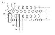
実施例4
図12(a)に示すように、3列の磁性トラック列を1群としてサブ領域を形成し、複数群のサブ領域を含むデータ領域を有するビットパターンド媒体を作製した。第1列〜第3列の磁性ドット列に含まれる磁性ドット43、44、45は互いに同位相である。Example 4
As shown in FIG. 12A, a bit patterned medium having a data region including a plurality of groups of sub-regions, in which sub-regions are formed with three magnetic track rows as a group, was fabricated. The
第1列〜第3列の磁性ドット列に含まれる磁性ドット43、44、45の形状については、クロストラック方向の幅を第1列で5nm、第2列で10nm、第3列で20nmとし、トラック方向の幅を第1列〜第3列のいずれも10nmとした。第1列〜第3列の各磁性ドット列に含まれる磁性ドット43、44、45の保磁力は、第1列で6000Oe、第2列で5000Oe、第3列で4030Oeであった。1つの磁性ドット列内でドットピッチを20nmとした。各磁性ドット列間の非磁性部の幅については、第1列と第2列との間の間隔を5nm、第2列と第3列との間の間隔を10nmとした。 Regarding the shape of the
この媒体に対して、記録素子の実効幅が50nm、再生素子の実効幅が50nmという仕様の磁気ヘッドで記録再生を行った。 Recording and reproduction were performed on this medium with a magnetic head having a specification that the effective width of the recording element was 50 nm and the effective width of the reproducing element was 50 nm.
記録時および再生時に、磁気ヘッドを第2列の磁性ドット列の中央に位置決めして、第1列〜第3列の磁性ドット列で同時に記録再生を行った。 At the time of recording and reproduction, the magnetic head was positioned at the center of the second magnetic dot row, and recording / reproduction was simultaneously performed with the first to third magnetic dot rows.
記録時には同じヘッド位置で3度記録を行い、記録電流Iwを初回で45mA、2回目で30mA、3回目で20mAとした。 During recording, recording was performed three times at the same head position, and the recording current Iw was set to 45 mA for the first time, 30 mA for the second time, and 20 mA for the third time.
3回の記録による磁化反転の状態を解析すると、図12(b)〜(d)に示す状態になっていることがわかった。すなわち、図12(b)に示すように初回で第1列〜第3列、図12(c)に示すように2回目で第2列および第3列、図12(d)に示すように3回目で第3列が記録されていた。このことは、保磁力の大きい磁性ドット列は記録電流Iwが小さいときには記録されないことを示している。 Analysis of the state of magnetization reversal by three recordings revealed that the states shown in FIGS. 12B to 12D were obtained. That is, as shown in FIG. 12B, the first to third columns are shown for the first time, as shown in FIG. 12C, the second and third rows are shown for the second time, as shown in FIG. The third row was recorded at the third time. This indicates that a magnetic dot row having a large coercive force is not recorded when the recording current Iw is small.
再生時には、第1列〜第3列の磁性ドット列を同時に読み取る。各磁性ドット列に含まれる磁性ドットのサイズに応じて、第1列の再生信号強度を±1とすると、第2列は±2倍の再生信号強度、第3列は±4倍の再生信号強度を持ち、これらの合計が1トラックの再生信号強度として得られる。この再生信号強度は各磁性ドットの記録状態に換算することができる。 During reproduction, the first to third magnetic dot rows are read simultaneously. According to the size of the magnetic dots included in each magnetic dot row, if the reproduction signal strength of the first row is ± 1, the second row is ± 2 times the reproduction signal strength and the third row is the ± 4 times reproduction signal. The sum of these is obtained as the reproduction signal intensity of one track. This reproduction signal intensity can be converted into the recording state of each magnetic dot.
したがって、本実施例によれば、実施例1よりも広い幅の再生素子を用いて記録再生を行うことができ、再生素子の製造マージンを改善することができる。また、本実施例によれば、瓦記録ではなく、通常の1トラックごとの記録方式を用いて記録再生を行うことができる。 Therefore, according to the present embodiment, recording / reproduction can be performed using a reproducing element having a width wider than that of the first embodiment, and the manufacturing margin of the reproducing element can be improved. Further, according to the present embodiment, recording / reproduction can be performed by using a normal recording method for each track, instead of tile recording.
本発明のいくつかの実施形態を説明したが、これらの実施形態は、例として提示したものであり、発明の範囲を限定することは意図していない。これら新規な実施形態は、その他の様々な形態で実施されることが可能であり、発明の要旨を逸脱しない範囲で、種々の省略、置き換え、変更を行うことができる。これら実施形態やその変形は、発明の範囲や要旨に含まれるとともに、特許請求の範囲に記載された発明とその均等の範囲に含まれる。 Although several embodiments of the present invention have been described, these embodiments are presented by way of example and are not intended to limit the scope of the invention. These novel embodiments can be implemented in various other forms, and various omissions, replacements, and changes can be made without departing from the scope of the invention. These embodiments and modifications thereof are included in the scope and gist of the invention, and are included in the invention described in the claims and the equivalents thereof.
1…ディスクドライブ、10…ディスク、11…スピンドルモータ、12W…記録素子、12R…再生素子、13…アクチュエータ、14…ヘッドアンプユニット、15…リード/ライトチャネル、16…ハードディスクコントローラ、17…マイクロプロセッサ、18…メモリ、19…モータドライバ、20…集積回路、30、31、32、33、34、35、36、37、41、42、43、44、45…磁性ドット、51…基板、52…レジスト層、53…導電化膜、54…電鋳層、55…ニッケルスタンパ、71…ガラス基板、72…磁気記録層、73…エッチング保護層、74…レジスト、75…非磁性層、76…表面保護層。 DESCRIPTION OF
Claims (11)
Translated fromJapanese複数の磁性ドット列をカバーする幅を有する磁気ヘッドと、
前記磁気ヘッドをクロストラック方向へ移動させるアクチュエータと
を具備し、第n列の磁性ドット列に含まれる磁性ドットの保磁力が、第n+1列の磁性ドット列に含まれる磁性ドットの保磁力より大きい磁気記録装置。A bit patterned medium having a data area including a plurality of magnetic dot rows each including a plurality of magnetic dots;
A magnetic head having a width covering a plurality of magnetic dot rows;
An actuator for moving the magnetic head in the cross-track direction, and the coercivity of the magnetic dots contained in the nth magnetic dot row is greater than the coercivity of the magnetic dots contained in the n + 1th magnetic dot row. Magnetic recording device.
Priority Applications (2)
| Application Number | Priority Date | Filing Date | Title |
|---|---|---|---|
| JP2010203603AJP2012059329A (en) | 2010-09-10 | 2010-09-10 | Magnetic recorder |
| US13/209,192US20120063028A1 (en) | 2010-09-10 | 2011-08-12 | Magnetic recording apparatus |
Applications Claiming Priority (1)
| Application Number | Priority Date | Filing Date | Title |
|---|---|---|---|
| JP2010203603AJP2012059329A (en) | 2010-09-10 | 2010-09-10 | Magnetic recorder |
Publications (1)
| Publication Number | Publication Date |
|---|---|
| JP2012059329Atrue JP2012059329A (en) | 2012-03-22 |
Family
ID=45806500
Family Applications (1)
| Application Number | Title | Priority Date | Filing Date |
|---|---|---|---|
| JP2010203603APendingJP2012059329A (en) | 2010-09-10 | 2010-09-10 | Magnetic recorder |
Country Status (2)
| Country | Link |
|---|---|
| US (1) | US20120063028A1 (en) |
| JP (1) | JP2012059329A (en) |
Families Citing this family (3)
| Publication number | Priority date | Publication date | Assignee | Title |
|---|---|---|---|---|
| JP5755607B2 (en)* | 2012-07-27 | 2015-07-29 | 株式会社東芝 | Magnetic recording medium and method for manufacturing the same |
| US8995073B1 (en)* | 2013-03-14 | 2015-03-31 | Seagate Technology Llc | Data storage mediums and devices having bit patterned media |
| US8873179B1 (en)* | 2013-09-12 | 2014-10-28 | HGST Netherlands B.V. | Bit-patterned media magnetic recording disk with two sizes of dots and imprint template made with directed self-assembly (DSA) of block copolymers |
Citations (7)
| Publication number | Priority date | Publication date | Assignee | Title |
|---|---|---|---|---|
| JP2002334414A (en)* | 2001-05-09 | 2002-11-22 | Toshiba Corp | Recording medium and method of manufacturing the same |
| JP2004164856A (en)* | 2002-09-19 | 2004-06-10 | Fuji Photo Film Co Ltd | Electron beam lithography method and disk-shaped carrier for high-density recording |
| JP2005116022A (en)* | 2003-10-06 | 2005-04-28 | Toshiba Corp | Magnetic recording medium manufacturing method, manufacturing apparatus, imprint stamper and manufacturing method thereof |
| JP2010040099A (en)* | 2008-08-05 | 2010-02-18 | Toshiba Storage Device Corp | Magnetic storage medium and magnetic recording device |
| JP2010157281A (en)* | 2008-12-26 | 2010-07-15 | Fujitsu Ltd | Magnetic recording medium, magnetic recording device, and method of manufacturing magnetic recording medium |
| JP2011060412A (en)* | 2009-09-09 | 2011-03-24 | Hitachi Global Storage Technologies Netherlands Bv | Asymmetrical writing device for single magnetic recording |
| JP2011134372A (en)* | 2009-12-22 | 2011-07-07 | Samsung Electronics Co Ltd | Device and method for reproducing magnetic signals |
- 2010
- 2010-09-10JPJP2010203603Apatent/JP2012059329A/enactivePending
- 2011
- 2011-08-12USUS13/209,192patent/US20120063028A1/ennot_activeAbandoned
Patent Citations (7)
| Publication number | Priority date | Publication date | Assignee | Title |
|---|---|---|---|---|
| JP2002334414A (en)* | 2001-05-09 | 2002-11-22 | Toshiba Corp | Recording medium and method of manufacturing the same |
| JP2004164856A (en)* | 2002-09-19 | 2004-06-10 | Fuji Photo Film Co Ltd | Electron beam lithography method and disk-shaped carrier for high-density recording |
| JP2005116022A (en)* | 2003-10-06 | 2005-04-28 | Toshiba Corp | Magnetic recording medium manufacturing method, manufacturing apparatus, imprint stamper and manufacturing method thereof |
| JP2010040099A (en)* | 2008-08-05 | 2010-02-18 | Toshiba Storage Device Corp | Magnetic storage medium and magnetic recording device |
| JP2010157281A (en)* | 2008-12-26 | 2010-07-15 | Fujitsu Ltd | Magnetic recording medium, magnetic recording device, and method of manufacturing magnetic recording medium |
| JP2011060412A (en)* | 2009-09-09 | 2011-03-24 | Hitachi Global Storage Technologies Netherlands Bv | Asymmetrical writing device for single magnetic recording |
| JP2011134372A (en)* | 2009-12-22 | 2011-07-07 | Samsung Electronics Co Ltd | Device and method for reproducing magnetic signals |
Also Published As
| Publication number | Publication date |
|---|---|
| US20120063028A1 (en) | 2012-03-15 |
Similar Documents
| Publication | Publication Date | Title |
|---|---|---|
| US7948701B2 (en) | Servo patterns for self-assembled island arrays | |
| JP4724060B2 (en) | Magnetic disk unit | |
| US6421195B1 (en) | Magnetic disk media with patterned sections | |
| Futamoto et al. | Investigation of 2 Gb/in/sup 2/magnetic recording at a track density of 17 kTPI | |
| JP4869418B2 (en) | Magnetic recording apparatus and magnetic recording method | |
| JP2008217967A (en) | Patterned magnetic recording medium having data island pattern and improved reading and writing, and magnetic recording apparatus incorporating the medium | |
| JP2012160233A (en) | Magnetic recording device and recording method for the same | |
| CN100401377C (en) | Magnetic recording disc drives and discs | |
| US7920354B2 (en) | Phase servo patterns for bit patterned media | |
| US7715137B2 (en) | Servo patterns for patterned media | |
| US20060061900A1 (en) | Magnetic recording medium, magnetic storage device, and fabricating method thereof | |
| US8824079B2 (en) | Servo patterns for bit patterned media with multiple dots per servo period | |
| JP2004199806A (en) | Recording / playback device | |
| JP3905898B2 (en) | Magnetic recording / reproducing device | |
| US7443622B2 (en) | Magnetic recording medium, magnetic recording/reproducing apparatus, and stamper for manufacturing the magnetic recording medium | |
| US8947809B2 (en) | Encoding scheme for bit patterned media | |
| CN113013326B (en) | Radially patterned media for circumferentially constrained grain growth | |
| JP2012059329A (en) | Magnetic recorder | |
| US8665549B2 (en) | Method for creating burst magnitude servo patterns with unipolar bits on a magnetic media of a magnetic data recording system | |
| US8737001B2 (en) | Bit patterned magnetic storage medium | |
| JP2003296911A (en) | Magnetic recording medium and magnetic recording / reproducing apparatus using the same | |
| JP2002373411A (en) | Magnetic recording medium and drive apparatus thereof | |
| JP2010231830A (en) | Magnetic storage medium and information storage device | |
| US8169728B2 (en) | Magnetic medium having an artificial pattern structure using a gradient of a magnetization reversal field and a method of use thereof | |
| JP4099180B2 (en) | Magnetic recording / reproducing device |
Legal Events
| Date | Code | Title | Description |
|---|---|---|---|
| A131 | Notification of reasons for refusal | Free format text:JAPANESE INTERMEDIATE CODE: A131 Effective date:20120110 | |
| A02 | Decision of refusal | Free format text:JAPANESE INTERMEDIATE CODE: A02 Effective date:20120508 |