JP2012059241A - Keyboard device for use with tablet personal computer - Google Patents
Keyboard device for use with tablet personal computerDownload PDFInfo
- Publication number
- JP2012059241A JP2012059241AJP2010247359AJP2010247359AJP2012059241AJP 2012059241 AJP2012059241 AJP 2012059241AJP 2010247359 AJP2010247359 AJP 2010247359AJP 2010247359 AJP2010247359 AJP 2010247359AJP 2012059241 AJP2012059241 AJP 2012059241A
- Authority
- JP
- Japan
- Prior art keywords
- base
- tablet
- upper lid
- personal computer
- keyboard device
- Prior art date
- Legal status (The legal status is an assumption and is not a legal conclusion. Google has not performed a legal analysis and makes no representation as to the accuracy of the status listed.)
- Pending
Links
Images


Classifications
- G—PHYSICS
- G06—COMPUTING OR CALCULATING; COUNTING
- G06F—ELECTRIC DIGITAL DATA PROCESSING
- G06F1/00—Details not covered by groups G06F3/00 - G06F13/00 and G06F21/00
- G06F1/16—Constructional details or arrangements
- G06F1/1613—Constructional details or arrangements for portable computers
- G06F1/1632—External expansion units, e.g. docking stations
- G—PHYSICS
- G06—COMPUTING OR CALCULATING; COUNTING
- G06F—ELECTRIC DIGITAL DATA PROCESSING
- G06F1/00—Details not covered by groups G06F3/00 - G06F13/00 and G06F21/00
- G06F1/16—Constructional details or arrangements
- G06F1/1613—Constructional details or arrangements for portable computers
- G06F1/1628—Enclosures for carrying portable computers with peripheral devices, e.g. cases for a laptop and a printer
- G—PHYSICS
- G06—COMPUTING OR CALCULATING; COUNTING
- G06F—ELECTRIC DIGITAL DATA PROCESSING
- G06F1/00—Details not covered by groups G06F3/00 - G06F13/00 and G06F21/00
- G06F1/16—Constructional details or arrangements
- G06F1/1613—Constructional details or arrangements for portable computers
- G06F1/1633—Constructional details or arrangements of portable computers not specific to the type of enclosures covered by groups G06F1/1615 - G06F1/1626
- G06F1/1662—Details related to the integrated keyboard
- G06F1/1669—Detachable keyboards
Landscapes
- Engineering & Computer Science (AREA)
- Theoretical Computer Science (AREA)
- Computer Hardware Design (AREA)
- Human Computer Interaction (AREA)
- Physics & Mathematics (AREA)
- General Engineering & Computer Science (AREA)
- General Physics & Mathematics (AREA)
- Input From Keyboards Or The Like (AREA)
- Casings For Electric Apparatus (AREA)
- Position Input By Displaying (AREA)
- Push-Button Switches (AREA)
Abstract
Description
Translated fromJapanese本発明は、キーボード装置に関し、より詳しくは、應用於タブレット型パソコンのキーボード装置に関する。 The present invention relates to a keyboard device, and more particularly, to a keyboard device for a tablet-type personal computer.
一般的に、パソコン周辺機器の入力装置はマウス、キーボード及びトラックボール等で、ここではキーボードは直接文字と記号をパソコンに入力出来る。このためユーザーや入力装置メーカーから相当に重視されている。次に従来のキーボードの構造と機能を説明する。次に従来のキーボードの構造と機能を説明する。従来のキーボード1は表面上に複数個のキーを有し、これらのキーは標準タイプキー10、テンキー11及びファンクションキー12等に分類される。これらのキーはユーザーに指で押されることで対応する信号を発信させコンピューターに送信し、コンピューターに押されたキーの機能を実行させる。例えば標準タイプキー10は英字等の記号を入力するために用い、テンキー11は数字を入力するために用い、ファンクションキー12は例えばF1〜F12等にある、各種機能を提供する。 Generally, the input devices of personal computer peripheral devices are a mouse, a keyboard, a trackball, and the like. Here, the keyboard can directly input characters and symbols to the personal computer. For this reason, considerable emphasis has been placed on users and input device manufacturers. Next, the structure and function of a conventional keyboard will be described. Next, the structure and function of a conventional keyboard will be described. The
科学技術の進歩に伴い、市場にはタブレット型パソコンが登場した。タブレット型パソコンは薄く軽量で、液晶ディスプレイのような外観を有し、またタブレット型パソコンのディスプレイはタッチスクリーン式ディスプレイとなっており、これによりタブレット型パソコンはタッチスクリーン式ディスプレイによりコマンドを入力されることで操作される。ユーザーがタブレット型パソコンを操作し、また文字或いは記号を入力する時、タブレット型パソコンのタッチスクリーン式ディスプレイはバーチャルキーボード装置のキーボードのグラフィックを表示し、ユーザーはキーボードのグラフィック上の各グラフィックをタッチすることで対応する文字或いは記号を入力でき、これによりタブレット型パソコンはキーボード装置と接続させることなく直接文字或いは記号を入力できる。 With the progress of science and technology, tablet computers have appeared in the market. Tablet PCs are thin and light and have a liquid crystal display-like appearance, and the tablet PC display is a touch screen display, which allows the tablet PC to input commands via the touch screen display. It is operated by. When the user operates the tablet computer and inputs characters or symbols, the touch screen display of the tablet computer displays the keyboard graphic of the virtual keyboard device, and the user touches each graphic on the keyboard graphic. Thus, the corresponding character or symbol can be input, and the tablet personal computer can directly input the character or symbol without being connected to the keyboard device.
タブレット型パソコンは薄く軽量な外観を有し、また外付けキーボード装置を必要とせず携帯に便利ではあるが、しかしながらパーソナルコンピューター或いはノートパソコンの使い方に慣れているユーザーはタッチスクリーン式ディスプレイを利用した文字或いは記号の入力に適応できず、これにより多くのユーザーは外付け式キーボード装置(この機能と構造は図1に図示する)を用意しタブレット型パソコンに接続し、タブレット型パソコンを例えばブックスタンド等のタブレット型パソコンを立て掛けられる物の上に立て掛け、タブレット型パソコンを一般的なディスプレイとして、外付け式キーボード装置を利用して文字或いは記号を入力し、ここでは外付け式キーボード装置をUSB(Universal Serial Bus,USB)接続によりタブレット型パソコンに接続する。 Tablet PCs have a thin and light appearance and do not require an external keyboard device, so they are convenient to carry. However, users who are used to using personal computers or laptop computers use touch screen displays. Alternatively, it cannot be applied to the input of symbols, so that many users prepare an external keyboard device (this function and structure is shown in FIG. 1) and connect it to a tablet computer. The tablet PC is leaned on an object that can be leaned, and the tablet PC is used as a general display, and characters or symbols are input using an external keyboard device. Here, the external keyboard device is connected to a USB (Universal Serial Bus , USB) connection to a tablet PC.
上記の設置方法はユーザーの習慣的な方法でタブレット型パソコンを操作できるが、しかしユーザーがタブレット型パソコンを携帯する時に必然的に外付け式キーボード装置を用意せねばならず、そうでなければ、ユーザーは外付け式キーボード装置を携帯せず、習慣的ではない方法である直接タッチスクリーン式ディスプレイ上のキーボードのグラフィックを使用し文字或いは記号を入力する方法を採らなければならない。上記のとおり、もしユーザーが習慣的な操作方法によるタブレット型パソコンの操作を希望するなら、外付け式キーボード装置の携帯は必須である。もしユーザーが外付け式キーボード装置の携帯を希望しないなら、直接タッチスクリーン式ディスプレイ上のキーボードのグラフィックを使用し文字或いは記号を入力しなければならない。上記の二つの方法はいずれもユーザーにとっては不便なもので、これにより携帯に便利で習慣的な操作方法による操作が可能なタブレット型パソコンのキーボード装置が必要であった。 The above installation method can operate the tablet PC in the user's customary manner, but the user must inevitably have an external keyboard device when carrying the tablet PC, The user does not carry an external keyboard device, and must adopt a method of inputting characters or symbols using a keyboard graphic on a direct touch screen display, which is an unconventional method. As mentioned above, if the user wishes to operate the tablet PC by a customary operation method, it is essential to carry an external keyboard device. If the user does not want to carry an external keyboard device, he or she must enter characters or symbols directly using the keyboard graphic on the touch screen display. Both of the above two methods are inconvenient for the user, and as a result, a keyboard device for a tablet-type personal computer that is convenient for carrying and can be operated by a customary operation method is required.
本発明は、このような従来の問題に鑑みてなされたものである。上記課題解決のため、本発明は、キー入力機能と収納機能を兼ね備えたタブレット型パソコン用キーボード装置を提供することを主目的とする。 The present invention has been made in view of such conventional problems. In order to solve the above problems, it is a main object of the present invention to provide a tablet personal computer keyboard device having both a key input function and a storage function.
本発明の好ましい実施形態においては、タブレット型パソコンを接続し前記タブレット型パソコンを収納するタブレット型パソコン用キーボード装置であって、
ベースの一端に設置され、前記ベースと一体成型となるハンドルと、
前記ベース上に設置され、少なくとも一つの文字或いは少なくとも一つのコマンドを前記タブレット型パソコンに入力する、複数個のキーからなるベースと、
前記ベースに接続され、また前記ベースに対向して回転し前記ベースに覆い被さり、或いは前記ベースとの間に夾角を形成し、また収納槽を有し、前記タブレット型パソコンを収容する上蓋を含み、
ここでは前記上蓋が前記ベースに対向し回転し前記ベースとの間に前記夾角を形成する時、前記ハンドルと前記上蓋は接触し前記上蓋が引き続き前記ベースに対向して回転するのを防ぐことを特徴とする、タブレット型パソコン用キーボード装置。In a preferred embodiment of the present invention, there is provided a keyboard device for a tablet PC that connects a tablet computer and stores the tablet computer,
A handle that is installed at one end of the base and is integrally molded with the base;
A base composed of a plurality of keys installed on the base for inputting at least one character or at least one command to the tablet computer;
A top cover that is connected to the base and rotates opposite to the base and covers the base, or forms a depression angle with the base, has a storage tank, and stores the tablet computer ,
Here, when the upper lid rotates to face the base and forms the depression angle with the base, the handle and the upper lid come into contact to prevent the upper lid from continuing to rotate against the base. A keyboard device for tablet computers.
本発明の好ましい実施形態においては、前記ベースは、前記複数個のキーと前記ベースの前記一端の間に設置され、前記タブレット型パソコンの一短辺を収容するのに用いられ、前記タブレット型パソコンが前記収納槽からはみ出すのを回避する収納槽をさらに含むことを特徴とする、タブレット型パソコン用キーボード装置。 In a preferred embodiment of the present invention, the base is installed between the plurality of keys and the one end of the base, and is used to accommodate one short side of the tablet personal computer. A keyboard device for a tablet-type personal computer, further comprising a storage tank that prevents the storage tank from protruding from the storage tank.
本発明の好ましい実施形態においては、前記タブレット型パソコンは第一ワイヤレス通信モジュールを含み、また前記ベースは、前記複数個のキーに接続され、前記第一ワイヤレス通信モジュールとの通信を行え前記複数個のキーにより入力される前記少なくとも一つの文字或いは前記少なくとも一つのコマンドを前記第一ワイヤレス通信モジュールに通信できる第二ワイヤレス通信モジュールをさらに含むことを特徴とするタブレット型パソコン用キーボード装置。 In a preferred embodiment of the present invention, the tablet personal computer includes a first wireless communication module, and the base is connected to the plurality of keys to communicate with the first wireless communication module. A keyboard device for a tablet-type personal computer, further comprising a second wireless communication module capable of communicating the at least one character or the at least one command input by the key to the first wireless communication module.
本発明の好ましい実施形態においては、前記第一ワイヤレス通信モジュールと前記第二ワイヤレス通信モジュールはブルートゥース通信モジュールであることを特徴とするタブレット型パソコン用キーボード装置。 In a preferred embodiment of the present invention, the first wireless communication module and the second wireless communication module are Bluetooth communication modules.
本発明の好ましい実施形態においては、前記上蓋は、
前記収納槽の一端に位置し、前記タブレット型パソコンの一短辺を外に露出させる補助槽と、
前記上蓋の一上縁に位置し、前記上縁に対向して移動するロック部材をさらに含み、前記ロック部材が前記上縁に対向してロック位置まで移動した時、前記タブレット型パソコンは前記ロック部材によりロックされ前記収納槽中に固定され、前記ロック部材が前記上縁に対向してロック解除位置まで移動した時、前記タブレット型パソコンは前記ロック部材によるロックを解除されることを特徴とするタブレット型パソコン用キーボード装置。In a preferred embodiment of the present invention, the upper lid is
An auxiliary tank located at one end of the storage tank and exposing one short side of the tablet PC;
A lock member is provided on one upper edge of the upper lid and moves to face the upper edge. When the lock member moves to the lock position to face the upper edge, the tablet PC is locked. The tablet PC is unlocked by the locking member when the locking member is locked by a member and fixed in the storage tank, and the locking member moves to the unlocking position facing the upper edge. Keyboard device for tablet PC.
本発明の好ましい実施形態においては、前記ハンドルは、電池を収納し前記電池の電力を出力させるための電池入れを含むことを特徴とするタブレット型パソコン用キーボード装置。 In a preferred embodiment of the present invention, the handle includes a battery compartment for storing a battery and outputting electric power of the battery.
本発明の好ましい実施形態においては、前記ベースは、前記ベースの他端に設置される第一磁性体をさらに含み、前記上蓋は、前記上縁に設置され、前記上蓋が前記ベースに対向して回転した時、前記第一磁性体を引き付け或いは前記第一磁性体により引き付けられ、前記上蓋に前記ベースを覆い被させる第二磁性体をさらに含むことを特徴とするタブレット型パソコン用キーボード装置。 In a preferred embodiment of the present invention, the base further includes a first magnetic body disposed at the other end of the base, the upper lid is disposed at the upper edge, and the upper lid is opposed to the base. A keyboard device for a tablet-type personal computer, further comprising a second magnetic body that attracts the first magnetic body or is attracted by the first magnetic body when rotated, and covers the base on the upper lid.
本発明の好ましい実施形態においては、前記ベースは、前記ベースの他端に設置される磁性体をさらに含み、前記上蓋は、前記上縁に設置され、前記上蓋が前記ベースに対向して回転した時に前記磁性体により引き付けられ、前記上蓋に前記ベースを覆い被させる金属部材をさらに含むことを特徴とするタブレット型パソコン用キーボード装置。 In a preferred embodiment of the present invention, the base further includes a magnetic body disposed at the other end of the base, the upper lid is disposed at the upper edge, and the upper lid is rotated to face the base. A keyboard device for a tablet personal computer, further comprising a metal member that is sometimes attracted by the magnetic body and covers the base on the upper lid.
本発明の好ましい実施形態においては、前記ベースは、前記ベースの他端に設置される金属部材をさらに含み、前記上蓋は、前記上縁に設置され、前記上蓋が前記ベースに対向して回転した時に前記金属部材を引き付け、前記上蓋に前記ベースを覆い被させる磁性体をさらに含むことを特徴とするタブレット型パソコン用キーボード装置。 In a preferred embodiment of the present invention, the base further includes a metal member installed at the other end of the base, the upper lid is installed at the upper edge, and the upper lid is rotated to face the base. A keyboard device for a tablet-type personal computer, further comprising a magnetic body that sometimes attracts the metal member and covers the base on the upper lid.
本発明の好ましい実施形態においては、前記ハンドルは、
前記ベースの前記一端の第一辺上に位置する第一ストッパー部と、
前記ベースの前記他端の第二辺上に位置する第二ストッパー部と、
前記第一ストッパー部が延長されることで形成され、前記上蓋の一端に挿入される第一回転軸と、
前記第二ストッパー部が延長されることで形成され、前記上蓋の他端に挿入され、前記上蓋を前記ベースに対抗させ回転させる第二回転軸をさらに含み、ここでは、前記上蓋が前記ベースに対向して回転し前記ベースとの間に前記夾角を形成した時、前記第一ストッパー部は前記上蓋の一端と接触し、また前記第二ストッパー部が前記上蓋の他端と接触し前記上蓋が引き続き前記ベースに対向して回転するのを防ぐことを特徴とするタブレット型パソコン用キーボード装置。In a preferred embodiment of the present invention, the handle is
A first stopper portion located on a first side of the one end of the base;
A second stopper portion located on the second side of the other end of the base;
A first rotating shaft formed by extending the first stopper portion and inserted into one end of the upper lid;
The second stopper part is formed by extending and inserted into the other end of the upper lid, and further includes a second rotating shaft that rotates the upper lid against the base, wherein the upper lid is attached to the base. When the opposite angle rotates to form the depression angle with the base, the first stopper portion comes into contact with one end of the upper lid, the second stopper portion comes into contact with the other end of the upper lid, and the upper lid A keyboard device for a tablet-type personal computer, characterized in that it is prevented from continuing to rotate against the base.
以下に図面を参照して本発明を実施するための形態について、詳細に説明する。なお、本発明は、以下に説明する実施形態に限定されるものではない。 EMBODIMENT OF THE INVENTION Below, the form for implementing this invention with reference to drawings is demonstrated in detail. Note that the present invention is not limited to the embodiments described below.
図2は本発明の好ましい実施形態に係るタブレット型パソコン用キーボード装置の操作時の状態の構造の概略図である。図2はタブレット型パソコン用キーボード装置2とタブレット型パソコン3を図示し、タブレット型パソコン3は短辺31と、第一ワイヤレス通信モジュール32と、電源キー33と、コネクトラインの挿入孔34及びロゴ35(図7に示す)で構成される。電源キー33とコネクトラインの挿入孔34はタブレット型パソコン3の短辺31上に設置され、電源キー33によりタブレット型パソコン3を起動或いは終了させ、コネクトラインの挿入孔34にはイヤホン或いはスピーカー等パソコン周辺機器である音響裝置(図示せず)の端子が挿入されパソコン周辺音響裝置とタブレット型パソコン3を接続し、本発明の好ましい実施形態においては、第一ワイヤレス通信モジュール32はブルートゥース通信モジュールである。 FIG. 2 is a schematic view of the structure of the tablet-type personal computer keyboard device according to a preferred embodiment of the present invention during operation. FIG. 2 illustrates a
本発明のタブレット型パソコン用キーボード装置2の操作時の状態は、タブレット型パソコン用キーボード装置2はベース21と上蓋22からなり、また上蓋22はベース21に接続され、ベース21に対向して回転しベース21との間に夾角A(図5に示す)を形成する。ベース21はハンドル211と、複数個のキー212と、収納槽213と、第二ワイヤレス通信モジュール214及び二つの第一磁性体215で構成される。ハンドル211はベース211の一端に設置され、またハンドル211とベース21一体成型となり、ユーザーはハンドル211を握って持てる。ハンドル211は第一ストッパー部2111と、第二ストッパー部2112と、第一回転軸2113及び第二回転軸2114で構成される。第一ストッパー部2111はベース21の一端の第一辺上(図2中の左辺)に位置し、第二ストッパー部2112はベース21の一端の第二辺上(図2中の右辺)に位置する。第一回転軸2113は第一ストッパー部2111が延長することで形成され、上蓋22の一端に挿入され、また第二回転軸2114は第二ストッパー部2112が延長することで形成され、上蓋22の他端に挿入され、ベース21は第一回転軸2113と第二回転軸2114により上蓋22に接続され、第一回転軸2113と第二回転軸2114により上蓋22はベース21に対向して回転する。 The tablet-type personal
複数個のキー212はベース22上に設置され、またベース22の外に露出し、ユーザーに押されることで前記複数個のキー212の対応する文字或いは記号を出力させる。収納槽213は複数個のキー212とベース21の一端の間に設置され、タブレット型パソコン3の短辺31を収納しタブレット型パソコン31が収納槽213からはみ出すのを回避する。第二ワイヤレス通信モジュール214は複数個のキー212に接続し、第一ワイヤレス通信モジュール32との通信を行い複数個のキー212の発信する文字或いは記号を第一ワイヤレス通信モジュール32へ送信する。二つの第一磁性体215はベース21の他端に設置され、本発明の好ましい実施形態においては、第二ワイヤレス通信モジュール214はブルートゥース通信モジュールであり、第一磁性体215は磁石である。 The plurality of
図2に示す、上蓋22は収納槽221と、補助槽222と、ロック部材223と、二つの第二磁性体224と、コネクトラインの収納槽225及び円型孔226で構成される。収納槽221はタブレット型パソコン3を収納し、補助槽222は収納槽221の一端に位置し、タブレット型パソコン3の短辺31を外へ露出させユーザーが指で触れられるようにする。ロック部材223は上蓋22の一上縁に位置し、一上縁に対抗して上下移動し、図2中の、ロック部材223はロック解除位置P1に位置する。二つの第二磁性体224は上蓋22の一上縁に設置され、上蓋22がベース21に対向し回転した時第一磁性体215を引き付け或いは第一磁性体215に引き付けられ、本発明の好ましい実施形態においては、第二磁性体224は磁石である。コネクトラインの収納槽225は上蓋22の一端に設置され、補助槽222の下方に位置する。 The
図3は本発明の好ましい実施形態に係るタブレット型パソコン用キーボード装置を別の角度から見た部分構造の分解図である。ハンドル211は電池入れ2115と電池蓋2216を含み、電池入れ2115は二つの電池23を収納し電池23の電力を出力し、複数個のキー212と第二ワイヤレス通信モジュール214を動作させる。電池蓋2216は電池入れ2115を覆い蓋をし電池入れ2115を外に露出させない。図3のとおり、ハンドル211はベース21と一体成型となり、またハンドル211はD字形状となる。 FIG. 3 is an exploded view of a partial structure of the keyboard device for a tablet personal computer according to a preferred embodiment of the present invention as seen from another angle. The
次にユーザーがタブレット型パソコン3をタブレット型パソコン用キーボード装置2に設置する時の状態を説明する。図4は本発明の好ましい実施形態に係るタブレット型パソコン用キーボード装置がタブレット型パソコンを収納した構造の概略図である。ユーザーがタブレット型パソコン用キーボード装置2を使用しタブレット型パソコン3を操作する時、まずタブレット型パソコン3を横にし上蓋22の収納槽221中にセットし、上蓋22の一上縁上に位置するロック部材223を下方に移動させ、ロック部材223をロック位置P2に位置させタブレット型パソコン3をロックし、タブレット型パソコン3が収納槽221からはみ出るのを回避する。当然ながら、ユーザーがタブレット型パソコン3を収納槽221から取り出す時は、ロック部材223をロック位置P2からロック解除位置P1まで移動させることでタブレット型パソコン3を取り出せる。 Next, a state when the user installs the tablet
タブレット型パソコン3が収納槽221中にセットされる時、タブレット型パソコン3の短辺31は補助槽222に隣接し、タブレット型パソコン3の短辺31を外に露出させる。タブレット型パソコン3の短辺31が外に露出されることにより、この短辺31上の電源キー33とコネクトラインの挿入孔34も外に露出され、ユーザーは指を補助槽222に入れ電源キー33を押しタブレット型パソコン3を起動或いは終了させる。この他、タブレット型パソコン3の短辺31上のコネクトラインの挿入孔34はコネクトラインの収納槽225の部分で露出され、ユーザーはイヤホン或いはスピーカー等のパソコン周辺音響裝置(図示せず)をコネクトラインの挿入孔34によりタブレット型パソコン3に接続でき、またパソコン周辺音響裝置のコネクターの端子はコネクトラインの収納槽225に収納される。 When the
ちなみに、ユーザーがタブレット型パソコン用キーボード装置2を操作する時、上蓋22は第一回転軸2113と第二回転軸2114を軸にベース21に対向して回転し、また上蓋22とベース21の間に夾角Aが形成される。タブレット型パソコン用キーボード装置2において、タブレット型パソコン3は上蓋22の収納槽221中に収納され、これにより上蓋22の重量は本来の重量に上蓋22とタブレット型パソコン3の重量を加え、上蓋22は重量の変化の影響でベース21に対向しての回転を続ける。しかしハンドル211の構造が上蓋22がベース21に対向して回転するのを妨げ、これは、ベース21の、第一ストッパー部2111の位置が第一回転軸2113に比べベース21の一端(図2中の左側に示す)により近接しており、第二ストッパー部2112の位置も第二回転軸2114に比べベース21の他端(図2中の右側に示す)により近接しており、これにより上蓋22がベース21に対向し回転する時、上蓋22の両端の下方が離れハンドル211の第一ストッパー部2111と第二ストッパー部2112に接触し、第一ストッパー部2111と第二ストッパー部2112に阻まれて上蓋22が引き続きベース21に対向して回転するのを止められ、上蓋22とベース21の間の夾角Aは約110度となり、これは図5に図示される。これにより、タブレット型パソコン3が収納槽221にセットされた時、上蓋22は重量の変化の影響によるベース21に対向しての回転を続けることはなくなる。また、タブレット型パソコン用キーボード装置2がワークスペース(一般的にデスク)上に置かれた時、ハンドル211はワークスペースに接触しタブレット型パソコン用キーボード装置2を支えタブレット型パソコン用キーボード装置2が倒れるのを防ぐ。 Incidentally, when the user operates the
タブレット型パソコン3のセットアップが完了した後、タブレット型パソコン3の第一ワイヤレス通信モジュール32が起動され、第一ワイヤレス通信モジュール32はベース21の第二ワイヤレス通信モジュール214と通信を行う。第一ワイヤレス通信モジュール32と第二ワイヤレス通信モジュール214の通信が確立した後、ユーザーはベース21上の複数個のキー212をタッチすることで対応する文字、記号或いはコマンドを発信でき、これらの文字、記号或いはコマンドは第二ワイヤレス通信モジュール214により第一ワイヤレス通信モジュール32に送信され、これによりこれらの文字、記号或いはコマンドはタブレット型パソコン3に出力される。 After the setup of the tablet
タブレット型パソコン3が収納槽221にセットされる以外にも、タブレット型パソコン用キーボード装置はさらに別の操作方法を有しており、図6は本発明の好ましい実施形態に係るタブレット型パソコン用キーボード装置がタブレット型パソコンを支える構造の概略図である。ベース21の収納槽213の長さはタブレット型パソコン3の短辺31より少し長く、これにより、ユーザーはタブレット型パソコン3を縦置きでベース21の収納槽213へセットでき、タブレット型パソコン3の短辺31を収納槽213に位置させ、またタブレット型パソコン3は上蓋22に支えられ倒れない。ユーザーは同様に複数個のキー212により文字、記号或いはコマンドをタブレット型パソコン3に入力できる。 In addition to setting the tablet-type
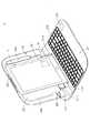
ユーザーが必要に迫られタブレット型パソコン3とタブレット型パソコン用キーボード装置2を携帯し外出した時、ユーザーはタブレット型パソコン3を収納槽221中にセットし、上蓋22をベース21に対向して回転させ、上蓋22がベース21に近接した時、ベース21と上蓋22中の第一磁性体215と第二磁性体224は磁力を発生させ相互に引き付け合い、上蓋22にベース21を覆わせ蓋をし、この時タブレット型パソコン用キーボード装置2はスーツケースの外観を呈し、ユーザーは手4でハンドル211を握り持ちタブレット型パソコン用キーボード装置2を携帯でき、またタブレット型パソコン3のロゴ35は円型孔226により外に露出され、これは図7に示す。上蓋22がベース21を覆い蓋をした時、ベース21と上蓋22中の第一磁性体215と第二磁性体224は相互に引き付け合い、これによりタブレット型パソコン用キーボード装置2の携帯中に上蓋22とベース21が剥離するのを回避できる。別の本発明の好ましい実施形態においては、上蓋の、第二磁性体は金属部材でもよく、上蓋ベースを覆い蓋をした時、上蓋の前記金属部材は第一磁性体に引き付けられ上蓋とベースの剥離を回避できる。同じように、ベースの第一磁性体も金属部材でもよく、前記金属部材は上蓋の第二磁性体に引き付けられる。 When the user needs to carry out the
上記のとおり、本発明のタブレット型パソコン用キーボード装置はユーザーの必要に応じその外観を変更でき、ユーザーがタブレット型パソコンを操作する時は、タブレット型パソコン用キーボード装置を開きタブレット型パソコンをこの中にセットし、ユーザーは習慣的な操作方法によりタブレット型パソコンを操作できる。またユーザーがタブレット型パソコン3とタブレット型パソコン用キーボード装置2を携帯する時は、タブレット型パソコン用キーボード装置の外観を変更させスーツケース型にして容易に携帯できる。また、本発明のタブレット型パソコン用キーボード装置のハンドルとベースは一体成型となり、タブレット型パソコン用キーボード装置の構造をさらに堅固にする。 As described above, the appearance of the tablet PC keyboard device of the present invention can be changed according to the user's needs, and when the user operates the tablet PC, the tablet PC keyboard device is opened and the tablet PC is set in this. The user can operate the tablet PC by a customary operation method. Further, when the user carries the
上記の実施形態は本発明の技術思想及び特徴を説明するためのものにすぎず、当前記技術分野を熟知する者に本発明の内容を理解させると共にこれをもって実施させることを目的とし、本発明の特許請求の範囲を限定するものではない。従って、本発明の精神を逸脱せずに行う各種の同様の効果をもつ改良又は変更は、後述の請求項に含まれるものとする。 The above embodiments are merely for explaining the technical idea and features of the present invention, and are intended to allow those skilled in the art to understand the contents of the present invention and to carry out the same with the present invention. It is not intended to limit the scope of the claims. Accordingly, improvements or modifications having various similar effects made without departing from the spirit of the present invention shall be included in the following claims.
1、2 キーボード装置
3 タブレット型パソコン
4 手
10 標準タイプキー
11 テンキー
12 ファンクションキー
21 ベース
22 上蓋
23 電池
31 短辺
32、214 ワイヤレス通信モジュール
33 電源キー
34 コネクトラインの挿入孔
35 ロゴ
211 ハンドル
212 キー
213 収納槽
215、224 磁性体
221 収納槽
222 補助槽
223 ロック部材
225 コネクトラインの収納槽
226 円型孔
2111、2112 ストッパー部
2113、2114 回転軸
2115 電池入れ
2116 電池蓋
A 夾角
P1 ロック解除位置
P2 ロック位置
1, 2 Keyboard device
3 Tablet PC
4 hands
10 Standard type key
11 Numeric keypad
12 Function keys
21 base
22 Upper lid
23 battery
31 Short side
32, 214 Wireless communication module
33 Power key
34 Insertion hole of connect line
35 logo
211 Handle
212 keys
213 Storage tank
215, 224 Magnetic material
221 storage tank
222 Auxiliary tank
223 Lock member
225 Connect line storage tank
226 circular hole
2111,2112 Stopper part
2113, 2114 Rotating shaft
2115 battery case
2116 Battery cover
A
P1 Unlock position
P2 lock position
Claims (10)
Translated fromJapaneseベースの一端に設置され、前記ベースと一体成型となるハンドルと、
前記ベース上に設置され、少なくとも一つの文字或いは少なくとも一つのコマンドを前記タブレット型パソコンに入力する、複数個のキーからなるベースと、
前記ベースに接続され、また前記ベースに対向して回転し前記ベースに覆い被さり、或いは前記ベースとの間に夾角を形成し、また収納槽を有し、前記タブレット型パソコンを収容する上蓋を含み、
ここでは前記上蓋が前記ベースに対向し回転し前記ベースとの間に前記夾角を形成する時、前記ハンドルと前記上蓋は接触し前記上蓋が引き続き前記ベースに対向して回転するのを防ぐことを特徴とする、タブレット型パソコン用キーボード装置。A keyboard device for a tablet computer that connects a tablet computer and stores the tablet computer,
A handle that is installed at one end of the base and is integrally molded with the base;
A base composed of a plurality of keys installed on the base for inputting at least one character or at least one command to the tablet computer;
A top cover that is connected to the base and rotates opposite to the base and covers the base, or forms a depression angle with the base, has a storage tank, and stores the tablet computer ,
Here, when the upper lid rotates to face the base and forms the depression angle with the base, the handle and the upper lid come into contact to prevent the upper lid from continuing to rotate against the base. A keyboard device for tablet computers.
前記収納槽の一端に位置し、前記タブレット型パソコンの一短辺を外に露出させる補助槽と、
前記上蓋の一上縁に位置し、前記上縁に対向して移動するロック部材をさらに含み、前記ロック部材が前記上縁に対向してロック位置まで移動した時、前記タブレット型パソコンは前記ロック部材によりロックされ前記収納槽中に固定され、前記ロック部材が前記上縁に対向してロック解除位置まで移動した時、前記タブレット型パソコンは前記ロック部材によるロックを解除されることを特徴とする、請求項1に記載のタブレット型パソコン用キーボード装置。The upper lid is
An auxiliary tank located at one end of the storage tank and exposing one short side of the tablet PC;
A lock member is provided on one upper edge of the upper lid and moves to face the upper edge. When the lock member moves to the lock position to face the upper edge, the tablet PC is locked. The tablet PC is unlocked by the locking member when the locking member is locked by a member and fixed in the storage tank, and the locking member moves to the unlocking position facing the upper edge. The keyboard device for a tablet-type personal computer according to claim 1.
前記ベースの前記一端の第一辺上に位置する第一ストッパー部と、
前記ベースの前記他端の第二辺上に位置する第二ストッパー部と、
前記第一ストッパー部が延長されることで形成され、前記上蓋の一端に挿入される第一回転軸と、
前記第二ストッパー部が延長されることで形成され、前記上蓋の他端に挿入され、前記上蓋を前記ベースに対抗させ回転させる第二回転軸をさらに含み、ここでは、前記上蓋が前記ベースに対向して回転し前記ベースとの間に前記夾角を形成した時、前記第一ストッパー部は前記上蓋の一端と接触し、また前記第二ストッパー部が前記上蓋の他端と接触し前記上蓋が引き続き前記ベースに対向して回転するのを防ぐことを特徴とする、請求項1に記載のタブレット型パソコン用キーボード装置。The handle is
A first stopper portion located on a first side of the one end of the base;
A second stopper portion located on the second side of the other end of the base;
A first rotating shaft formed by extending the first stopper portion and inserted into one end of the upper lid;
The second stopper part is formed by extending and inserted into the other end of the upper lid, and further includes a second rotating shaft that rotates the upper lid against the base, wherein the upper lid is attached to the base. When the opposite angle rotates to form the depression angle with the base, the first stopper portion comes into contact with one end of the upper lid, the second stopper portion comes into contact with the other end of the upper lid, and the upper lid The keyboard device for a tablet-type personal computer according to claim 1, wherein the keyboard device is prevented from continuing to rotate against the base.
Applications Claiming Priority (2)
| Application Number | Priority Date | Filing Date | Title |
|---|---|---|---|
| TW099129828 | 2010-09-03 | ||
| TW099129828ATWI426415B (en) | 2010-09-03 | 2010-09-03 | Keyboard device for tablet personal computer |
Publications (1)
| Publication Number | Publication Date |
|---|---|
| JP2012059241Atrue JP2012059241A (en) | 2012-03-22 |
Family
ID=43735750
Family Applications (1)
| Application Number | Title | Priority Date | Filing Date |
|---|---|---|---|
| JP2010247359APendingJP2012059241A (en) | 2010-09-03 | 2010-11-04 | Keyboard device for use with tablet personal computer |
Country Status (4)
| Country | Link |
|---|---|
| US (1) | US8369074B2 (en) |
| EP (1) | EP2426571A3 (en) |
| JP (1) | JP2012059241A (en) |
| TW (1) | TWI426415B (en) |
Cited By (1)
| Publication number | Priority date | Publication date | Assignee | Title |
|---|---|---|---|---|
| JP5947966B1 (en)* | 2015-08-25 | 2016-07-06 | レノボ・シンガポール・プライベート・リミテッド | Stand device and electronic device |
Families Citing this family (42)
| Publication number | Priority date | Publication date | Assignee | Title |
|---|---|---|---|---|
| NZ594007A (en) | 2010-06-07 | 2014-03-28 | Targus Group Internat Inc | Portable electronic device case accessories and related systems and methods |
| US11134580B2 (en) | 2010-07-08 | 2021-09-28 | Zagg Inc | Protective cover for portable electronic device and associated systems and methods |
| US20120008269A1 (en)* | 2010-07-08 | 2012-01-12 | David Gengler | Protective cover for a mobile computing device, systems including protective covers, and associated methods |
| US8467186B2 (en)* | 2010-12-07 | 2013-06-18 | Adonit Co. Ltd. | Tablet PC cover with integral keyboard |
| US20120229970A1 (en)* | 2011-03-11 | 2012-09-13 | Mao-Jung Hsu | Box for Placing and Supporting a Tablet PC on a Table |
| US9494975B1 (en)* | 2011-03-28 | 2016-11-15 | Amazon Technologies, Inc. | Accessory device identification method |
| US20130183899A1 (en)* | 2011-05-18 | 2013-07-18 | Sony Mobile Communications Ab | Wireless keyboard for mobile device |
| US9218024B2 (en) | 2011-06-23 | 2015-12-22 | Zagg Intellectual Property Holding Co., Inc. | Accessory and support for electronic devices, systems including the same and methods |
| US20120327580A1 (en)* | 2011-06-23 | 2012-12-27 | Zagg Intellectual Property Holding Co., Inc. | Protective devices and systems for portable electronic devices and associated methods |
| TWI442266B (en)* | 2011-07-08 | 2014-06-21 | Primax Electronics Ltd | Input device for tablet computer |
| CN202257383U (en)* | 2011-10-10 | 2012-05-30 | 深圳市保绿源硅橡胶科技有限公司 | Support device of tablet personal computer |
| US20130128432A1 (en)* | 2011-11-21 | 2013-05-23 | Asustek Computer Inc. | Portable electronic device |
| TWI481996B (en)* | 2011-12-14 | 2015-04-21 | Wistron Corp | Support stand and electronic device having the same |
| US9141136B2 (en)* | 2012-01-08 | 2015-09-22 | Parle Innovation, Inc. | Tablet computer carrying case with retractable latch |
| US9189020B2 (en) | 2012-03-16 | 2015-11-17 | Cisco Technology, Inc. | Portable computing device with cover providing access and control of applications |
| US20150309557A1 (en)* | 2012-07-02 | 2015-10-29 | Guowen Hu | Insertable housing for electronic device |
| US9069527B2 (en) | 2012-07-26 | 2015-06-30 | Brydge Llc | Tablet support apparatus |
| US9494976B2 (en) | 2012-09-11 | 2016-11-15 | Logitech Europe S.A. | Protective cover for a tablet computer |
| USD705764S1 (en) | 2012-09-12 | 2014-05-27 | Targus Group International, Inc. | Wallet portable electronic device case |
| US8720843B1 (en)* | 2012-11-27 | 2014-05-13 | Tsan-Nien Chen | Protective cover |
| US11262791B2 (en)* | 2013-01-03 | 2022-03-01 | Correll Electronics, Llc | Electronic device combination |
| US9939842B2 (en)* | 2013-01-03 | 2018-04-10 | Carroll Boston Correll, JR. | Electronic device combination |
| TW201428569A (en)* | 2013-01-10 | 2014-07-16 | Sipix Technology Inc | Display system having electrophoretic touch panel |
| US8763795B1 (en) | 2013-01-23 | 2014-07-01 | Targus Group International, Inc. | Dual support flap case |
| USD716783S1 (en) | 2013-04-15 | 2014-11-04 | Targus Group International, Inc. | Slim case |
| US9110630B2 (en) | 2013-07-25 | 2015-08-18 | Targus Group International, Inc. | Portable electronic device case with an adhesive panel |
| EP3129848A4 (en) | 2014-04-09 | 2017-04-19 | Microsoft Technology Licensing, LLC | Hinged cover for computing device |
| KR102107275B1 (en)* | 2014-04-10 | 2020-05-06 | 마이크로소프트 테크놀로지 라이센싱, 엘엘씨 | Collapsible shell cover for computing device |
| KR20160143784A (en) | 2014-04-10 | 2016-12-14 | 마이크로소프트 테크놀로지 라이센싱, 엘엘씨 | Slider cover for computing devices |
| US9750321B2 (en) | 2014-06-13 | 2017-09-05 | Targus Group International, Inc. | Case for portable electronic devices with internal support |
| US9717314B2 (en) | 2014-06-27 | 2017-08-01 | Targus International Llc | Case for portable electronic devices with shutter stand |
| CN106662891B (en) | 2014-10-30 | 2019-10-11 | 微软技术许可有限责任公司 | Multi-configuration input equipment |
| US9600034B2 (en)* | 2015-02-13 | 2017-03-21 | Google Inc. | Attaching computing device to mount by magnets |
| WO2016149101A1 (en) | 2015-03-18 | 2016-09-22 | Targus International Llc | Extendable, universal case for portable electronic devices |
| US9971379B2 (en)* | 2015-08-26 | 2018-05-15 | Apple Inc. | Attachment features for an accessory device |
| CN106815890A (en)* | 2015-11-27 | 2017-06-09 | 南京亚士德科技有限公司 | Drive recorder |
| US9824836B1 (en) | 2016-05-16 | 2017-11-21 | ACCO Brands Corporation | Input device for electronic device |
| USD806067S1 (en)* | 2016-09-10 | 2017-12-26 | Compal Electronics, Inc. | Notebook computer |
| CN114077284A (en)* | 2020-08-21 | 2022-02-22 | 神讯电脑(昆山)有限公司 | A functional testing system and method of a tablet computer base |
| CN115877956A (en)* | 2021-09-30 | 2023-03-31 | 华为技术有限公司 | A keyboard assembly and electronic equipment |
| EP4375810A1 (en)* | 2022-11-28 | 2024-05-29 | Getac Technology Corporation | Portable keyboard assembly and electronic device |
| JP2024110099A (en)* | 2023-02-02 | 2024-08-15 | レノボ・シンガポール・プライベート・リミテッド | Stand and keyboard stand set |
Citations (19)
| Publication number | Priority date | Publication date | Assignee | Title |
|---|---|---|---|---|
| JPH04266111A (en)* | 1991-02-20 | 1992-09-22 | Pfu Ltd | Note type information processor |
| JPH04333121A (en)* | 1991-05-08 | 1992-11-20 | Omron Corp | Keyboard |
| JPH0535318U (en)* | 1991-10-11 | 1993-05-14 | キヤノン株式会社 | Portable electronic devices |
| JPH05313786A (en)* | 1992-05-13 | 1993-11-26 | Hitachi Ltd | Information processing equipment |
| JPH0854959A (en)* | 1994-08-11 | 1996-02-27 | Hitachi Ltd | Portable information processing device |
| JPH1049262A (en)* | 1996-08-06 | 1998-02-20 | Nec Yonezawa Ltd | Notebook type personal computer |
| JP2000177181A (en)* | 1998-12-18 | 2000-06-27 | King Jim Co Ltd | Character information processing device |
| EP1016951A1 (en)* | 1998-11-12 | 2000-07-05 | NTS Computer Systems R & D (Ireland) Limited | A portable computer |
| JP2001101140A (en)* | 1999-09-30 | 2001-04-13 | Pfu Ltd | Cradle for mobile information terminal |
| JP3082025U (en)* | 2001-05-23 | 2001-11-30 | 詮泰科技股▲分▼有限公司 | Portable computer input device |
| JP2002073212A (en)* | 2000-08-31 | 2002-03-12 | Sony Corp | Information processor |
| JP2002341998A (en)* | 2001-05-16 | 2002-11-29 | Casio Comput Co Ltd | Information processing device and character input device |
| JP2004070620A (en)* | 2002-08-06 | 2004-03-04 | Citizen Watch Co Ltd | Electronic device |
| US20060018089A1 (en)* | 2004-07-23 | 2006-01-26 | Chun-Chien Chou | Notebook type keyboard apparatus |
| JP2006024178A (en)* | 2004-07-09 | 2006-01-26 | Tatung Co | Folding computer cover |
| JP2008090872A (en)* | 2008-01-21 | 2008-04-17 | I-O Data Device Inc | Data input device |
| JP2008129965A (en)* | 2006-11-24 | 2008-06-05 | Sony Corp | Computer device and system |
| JP3156174U (en)* | 2009-06-24 | 2009-12-17 | 微星科技股▲分▼有限公司 | Projection electronic device |
| JP2012216199A (en)* | 2011-03-25 | 2012-11-08 | Panasonic Corp | Holding device and electronic device including the same |
Family Cites Families (14)
| Publication number | Priority date | Publication date | Assignee | Title |
|---|---|---|---|---|
| US5295089A (en)* | 1992-05-28 | 1994-03-15 | Emilio Ambasz | Soft, foldable consumer electronic products |
| US6108200A (en)* | 1998-10-13 | 2000-08-22 | Fullerton; Robert L. | Handheld computer keyboard system |
| US6343006B1 (en)* | 1998-11-20 | 2002-01-29 | Jerry Moscovitch | Computer display screen system and adjustable screen mount, and swinging screens therefor |
| TW449945B (en)* | 2000-08-01 | 2001-08-11 | Hon Hai Prec Ind Co Ltd | Plane printed antenna |
| US6788527B2 (en)* | 2002-05-31 | 2004-09-07 | Hewlett-Packard Development Company, L.P. | Tablet computer keyboard and system and method incorporating same |
| KR100488012B1 (en)* | 2002-11-11 | 2005-05-06 | 엘지전자 주식회사 | Portable computer system |
| TWM243698U (en)* | 2003-10-14 | 2004-09-11 | First Int Computer Inc | Assembly of panel computer which can be retrieved and turned over |
| TWM245523U (en)* | 2003-11-20 | 2004-10-01 | Tatung Co | Portable computer keyboard expanding base |
| TWI265770B (en)* | 2005-06-15 | 2006-11-01 | Asustek Comp Inc | Portable computer |
| TWM291657U (en)* | 2005-09-19 | 2006-06-01 | Inventec Corp | Portable electronic apparatus |
| TWI301528B (en)* | 2006-06-29 | 2008-10-01 | Arima Computer Corp | Tablet pc and method for sustaining the same |
| TWI324719B (en)* | 2007-02-09 | 2010-05-11 | Fujitsu Ltd | Connecting module and electronic device coupling system |
| US8730669B2 (en)* | 2008-08-15 | 2014-05-20 | Lenovo (Singapore) Pte. Ltd. | Transformer case for notebook slate computer with wireless keyboard |
| CN101770260B (en)* | 2009-01-05 | 2012-07-25 | 联想(北京)有限公司 | Detachable-portable computing equipment |
- 2010
- 2010-09-03TWTW099129828Apatent/TWI426415B/ennot_activeIP Right Cessation
- 2010-11-04JPJP2010247359Apatent/JP2012059241A/enactivePending
- 2010-11-05USUS12/940,572patent/US8369074B2/ennot_activeExpired - Fee Related
- 2011
- 2011-02-09EPEP11153767Apatent/EP2426571A3/ennot_activeWithdrawn
Patent Citations (19)
| Publication number | Priority date | Publication date | Assignee | Title |
|---|---|---|---|---|
| JPH04266111A (en)* | 1991-02-20 | 1992-09-22 | Pfu Ltd | Note type information processor |
| JPH04333121A (en)* | 1991-05-08 | 1992-11-20 | Omron Corp | Keyboard |
| JPH0535318U (en)* | 1991-10-11 | 1993-05-14 | キヤノン株式会社 | Portable electronic devices |
| JPH05313786A (en)* | 1992-05-13 | 1993-11-26 | Hitachi Ltd | Information processing equipment |
| JPH0854959A (en)* | 1994-08-11 | 1996-02-27 | Hitachi Ltd | Portable information processing device |
| JPH1049262A (en)* | 1996-08-06 | 1998-02-20 | Nec Yonezawa Ltd | Notebook type personal computer |
| EP1016951A1 (en)* | 1998-11-12 | 2000-07-05 | NTS Computer Systems R & D (Ireland) Limited | A portable computer |
| JP2000177181A (en)* | 1998-12-18 | 2000-06-27 | King Jim Co Ltd | Character information processing device |
| JP2001101140A (en)* | 1999-09-30 | 2001-04-13 | Pfu Ltd | Cradle for mobile information terminal |
| JP2002073212A (en)* | 2000-08-31 | 2002-03-12 | Sony Corp | Information processor |
| JP2002341998A (en)* | 2001-05-16 | 2002-11-29 | Casio Comput Co Ltd | Information processing device and character input device |
| JP3082025U (en)* | 2001-05-23 | 2001-11-30 | 詮泰科技股▲分▼有限公司 | Portable computer input device |
| JP2004070620A (en)* | 2002-08-06 | 2004-03-04 | Citizen Watch Co Ltd | Electronic device |
| JP2006024178A (en)* | 2004-07-09 | 2006-01-26 | Tatung Co | Folding computer cover |
| US20060018089A1 (en)* | 2004-07-23 | 2006-01-26 | Chun-Chien Chou | Notebook type keyboard apparatus |
| JP2008129965A (en)* | 2006-11-24 | 2008-06-05 | Sony Corp | Computer device and system |
| JP2008090872A (en)* | 2008-01-21 | 2008-04-17 | I-O Data Device Inc | Data input device |
| JP3156174U (en)* | 2009-06-24 | 2009-12-17 | 微星科技股▲分▼有限公司 | Projection electronic device |
| JP2012216199A (en)* | 2011-03-25 | 2012-11-08 | Panasonic Corp | Holding device and electronic device including the same |
Cited By (1)
| Publication number | Priority date | Publication date | Assignee | Title |
|---|---|---|---|---|
| JP5947966B1 (en)* | 2015-08-25 | 2016-07-06 | レノボ・シンガポール・プライベート・リミテッド | Stand device and electronic device |
Also Published As
| Publication number | Publication date |
|---|---|
| EP2426571A2 (en) | 2012-03-07 |
| TW201211829A (en) | 2012-03-16 |
| US8369074B2 (en) | 2013-02-05 |
| US20120057288A1 (en) | 2012-03-08 |
| EP2426571A3 (en) | 2012-12-19 |
| TWI426415B (en) | 2014-02-11 |
Similar Documents
| Publication | Publication Date | Title |
|---|---|---|
| JP2012059241A (en) | Keyboard device for use with tablet personal computer | |
| JP2012138067A (en) | Notebook computer | |
| TWI472903B (en) | Docking station | |
| CN102563304B (en) | Electronic device support and the electronic equipment with electronic device support | |
| US9532631B2 (en) | Hinged cover for computing device | |
| US20060171112A1 (en) | System and method for locking a tablet computer display | |
| TW201430524A (en) | Electronic device | |
| CN213659288U (en) | Cases, Kits and Electronics | |
| JP2014146313A (en) | Notebook-sized personal computer | |
| JP2013089257A (en) | Portable electronic equipment | |
| TW201610831A (en) | Multi-screen display device | |
| WO2015180279A1 (en) | Rotating-shaft mobile telephone protective case with keyboard | |
| CN203397260U (en) | Mobile device protective sleeve with input function | |
| US20110090180A1 (en) | Stylus and electronic device utilizing the same | |
| JP2005174338A (en) | Portable electronic device and method of reading data from optical storage medium | |
| US20120262890A1 (en) | Electronic device with depressible and rotatable wheel | |
| TWM447531U (en) | A keyboard structure for storing a touch pen | |
| TWM312180U (en) | Mobile electronic apparatus having a touch pen | |
| CN101655721B (en) | Portable computer | |
| JP2017016621A (en) | Input device for tablet terminal | |
| CN204790889U (en) | Mouse and have notebook computer of built -in mouse | |
| JP4547588B2 (en) | Information processing device | |
| CN114241894A (en) | Electronic display device | |
| CN204790678U (en) | Supporting device and computer device using same | |
| CN216561629U (en) | Hardware and tablet computer protective sleeve with Bluetooth keyboard |
Legal Events
| Date | Code | Title | Description |
|---|---|---|---|
| A621 | Written request for application examination | Free format text:JAPANESE INTERMEDIATE CODE: A621 Effective date:20131029 | |
| A131 | Notification of reasons for refusal | Free format text:JAPANESE INTERMEDIATE CODE: A131 Effective date:20140826 | |
| A977 | Report on retrieval | Free format text:JAPANESE INTERMEDIATE CODE: A971007 Effective date:20140827 | |
| A02 | Decision of refusal | Free format text:JAPANESE INTERMEDIATE CODE: A02 Effective date:20150210 |