JP2012055569A - Endoscope - Google Patents
EndoscopeDownload PDFInfo
- Publication number
- JP2012055569A JP2012055569AJP2010203392AJP2010203392AJP2012055569AJP 2012055569 AJP2012055569 AJP 2012055569AJP 2010203392 AJP2010203392 AJP 2010203392AJP 2010203392 AJP2010203392 AJP 2010203392AJP 2012055569 AJP2012055569 AJP 2012055569A
- Authority
- JP
- Japan
- Prior art keywords
- wire
- pulley
- lever
- pulling
- traction
- Prior art date
- Legal status (The legal status is an assumption and is not a legal conclusion. Google has not performed a legal analysis and makes no representation as to the accuracy of the status listed.)
- Pending
Links
Images


Classifications
- A—HUMAN NECESSITIES
- A61—MEDICAL OR VETERINARY SCIENCE; HYGIENE
- A61B—DIAGNOSIS; SURGERY; IDENTIFICATION
- A61B1/00—Instruments for performing medical examinations of the interior of cavities or tubes of the body by visual or photographical inspection, e.g. endoscopes; Illuminating arrangements therefor
- A61B1/00064—Constructional details of the endoscope body
- A61B1/00071—Insertion part of the endoscope body
- A61B1/00078—Insertion part of the endoscope body with stiffening means
Landscapes
- Health & Medical Sciences (AREA)
- Life Sciences & Earth Sciences (AREA)
- Surgery (AREA)
- Biomedical Technology (AREA)
- Medical Informatics (AREA)
- Optics & Photonics (AREA)
- Pathology (AREA)
- Radiology & Medical Imaging (AREA)
- Biophysics (AREA)
- Engineering & Computer Science (AREA)
- Physics & Mathematics (AREA)
- Heart & Thoracic Surgery (AREA)
- Nuclear Medicine, Radiotherapy & Molecular Imaging (AREA)
- Molecular Biology (AREA)
- Animal Behavior & Ethology (AREA)
- General Health & Medical Sciences (AREA)
- Public Health (AREA)
- Veterinary Medicine (AREA)
- Endoscopes (AREA)
- Instruments For Viewing The Inside Of Hollow Bodies (AREA)
Abstract
Translated fromJapaneseDescription
Translated fromJapanese本発明は内視鏡に係り、特に挿入部の可撓性を調整可能な内視鏡に関する。 The present invention relates to an endoscope, and more particularly to an endoscope capable of adjusting the flexibility of an insertion portion.
医療分野において、内視鏡を利用した医療診断が広く行われている。特に、体腔内に挿入される内視鏡の挿入部の先端部にCCD等の撮像素子を内蔵して体腔内の画像を撮影し、プロセッサ装置で信号処理を施してモニタに画像表示し、これを医者が観察して診断に用いたり、あるいは、処置具挿通用のチャンネルから処置具を挿入して、例えばポリープの切除等の処置を施したりしている。 In the medical field, medical diagnosis using an endoscope is widely performed. In particular, an imaging element such as a CCD is incorporated at the distal end of the insertion portion of the endoscope that is inserted into the body cavity, and an image inside the body cavity is taken, signal processing is performed by the processor device, and the image is displayed on the monitor. The doctor observes and uses it for diagnosis, or inserts a treatment tool from a channel for inserting the treatment tool to perform treatment such as polyp excision.
内視鏡は、施術者が把持して操作する手元操作部と、この手元操作部に接続されて体腔内等に挿入される挿入部と、手元操作部に接続されて光源装置、プロセッサ装置に接続されるユニバーサルケーブルとによって構成されている。 The endoscope includes a hand operating unit that is gripped and operated by the practitioner, an insertion unit that is connected to the hand operating unit and inserted into a body cavity, etc., and a light source device and a processor device that are connected to the hand operating unit. And a universal cable to be connected.
内視鏡の挿入部は、複雑に屈曲した挿入経路内にも挿入できるように、可撓性を有する軟性部を有している。しかし、この可撓性のために挿入部の先端側の方向が定まらず、目標とする方向に挿入することが難しいという問題がある。また、体腔内に挿入部を挿入している際、何らかの処置や観察を行うために、挿入部がその時の形状で固定されていることが望ましい場合がある。 The insertion portion of the endoscope has a flexible portion having flexibility so that the insertion portion can be inserted into a complicatedly bent insertion path. However, due to this flexibility, the direction of the distal end side of the insertion portion is not fixed, and there is a problem that it is difficult to insert in the target direction. Further, when the insertion portion is inserted into the body cavity, it may be desirable that the insertion portion is fixed in the shape at that time in order to perform some treatment or observation.
そこで、特許文献1に開示された内視鏡は、挿入部の軟性部に可撓性可変部材(硬度可変部材ともいう)である密着コイルばねを挿通配置するともに、この密着コイルばねに牽引部材であるワイヤを挿通し、このワイヤを牽引及び弛緩して密着コイルばねを伸縮させることにより、軟性部の可撓性を調整している。 Therefore, the endoscope disclosed in Patent Document 1 has a close contact coil spring, which is a flexible variable member (also referred to as a hardness variable member), inserted in the soft portion of the insertion portion, and a pulling member attached to the close contact coil spring. The flexibility of the soft part is adjusted by inserting a wire, and pulling and relaxing the wire to expand and contract the close coil spring.
前記ワイヤを牽引及び弛緩する牽引機構部は、内視鏡の手元操作部に設けられている。この牽引機構部は、前記ワイヤの端部に連結された第1のリンク部材と、第1のリンク部材に連結された第2のリンク部材と、第2のリンク部材に連結された操作レバーとからなる。第2のリンク部材は、操作レバーの円板状基端部の外周部に回動自在に連結され、また、操作レバーは手元操作部に回動自在に取り付けられるとともに、頂部に指当部が設けられている。この指当部に指を押し当てて操作レバーを回動操作すると、この回動操作力が第2及び第1のリンク部材を介することにより直線運動に変換されてワイヤが牽引及び弛緩される。この操作によって密着コイルばねが伸縮し、軟性部の可撓性が変化する。 A pulling mechanism section that pulls and relaxes the wire is provided in a hand operation section of the endoscope. The traction mechanism includes a first link member coupled to the end of the wire, a second link member coupled to the first link member, and an operation lever coupled to the second link member, Consists of. The second link member is rotatably connected to the outer peripheral portion of the disc-shaped base end portion of the operation lever, and the operation lever is rotatably attached to the hand operation portion, and the finger holder is on the top portion. Is provided. When the operating lever is rotated by pressing the finger against the finger holder, the rotating operation force is converted into linear motion via the second and first link members, and the wire is pulled and relaxed. By this operation, the contact coil spring expands and contracts, and the flexibility of the soft part changes.
特許文献1の牽引機構部は、操作レバーの1回(1ストローク)の回動操作でワイヤを牽引及び弛緩する機構である。よって、特許文献1の牽引機構部では、軟性部の可撓性を調整するためのワイヤ牽引量を確保するために、円板状基端部の径を大きくする必要があるので、牽引機構部が大型化するという問題があった。また、ワイヤの牽引力は数十キロにも及ぶことから、操作レバーを指で操作する操作力を得るためには、円板状基端部の大径化に伴い操作レバーの長さを長くしなければならず、これもまた牽引機構部の大型化につながるという問題があった。 The pulling mechanism part of Patent Document 1 is a mechanism that pulls and relaxes a wire by a single rotation (one stroke) of an operation lever. Therefore, in the traction mechanism portion of Patent Document 1, it is necessary to increase the diameter of the disc-shaped base end portion in order to ensure the wire traction amount for adjusting the flexibility of the soft portion. There was a problem of increasing the size. In addition, since the pulling force of the wire reaches several tens of kilometers, in order to obtain the operating force to operate the operating lever with a finger, the length of the operating lever is increased as the diameter of the base end of the disk is increased. This also has the problem that this leads to an increase in the size of the traction mechanism.
本発明はこのような事情に鑑みてなされたもので、牽引機構部の小型化を図るとともにワイヤの牽引操作力を低減することができる内視鏡を提供することを目的とする。 The present invention has been made in view of such circumstances, and an object thereof is to provide an endoscope capable of reducing the pulling operation force of the wire while reducing the size of the pulling mechanism portion.
前記目的を達成するために、本発明に係る内視鏡は、手元操作部と、該手元操作部に基端部が接続された挿入部とからなる内視鏡であって、前記挿入部は、前記手元操作部に基端部が接続された軟性部と、該軟性部の先端部に基端部が接続された湾曲部と、該湾曲部の先端部に基端部が接続された先端硬質部からなる内視鏡において、前記軟性部の先端部側に一端が固定されるとともに他端が前記挿入部の基端部又は前記手元操作部側に固定され、伸縮により可撓性が変化する可撓性可変部材と、前記可撓性可変部材に挿通され、一端が前記軟性部の前記先端側に固定されるとともに他端が前記手元操作部に設けられた牽引機構部に連結されたワイヤとを有し、前記牽引機構部は、前記ワイヤの他端が巻回されるプーリと、前記プーリに回転駆動力を与えるとともに前記プーリに自己制動力を与えるウォームギヤを有する減速機構部と、を備えることを特徴とする。 In order to achieve the above object, an endoscope according to the present invention is an endoscope including a hand operation part and an insertion part having a proximal end connected to the hand operation part, wherein the insertion part is A flexible portion having a proximal end connected to the hand operation portion, a bending portion having a proximal end connected to the distal end of the flexible portion, and a distal end having a proximal end connected to the distal end of the bending portion In an endoscope composed of a hard part, one end is fixed to the distal end side of the soft part and the other end is fixed to the proximal end part of the insertion part or the hand operation part side, and the flexibility changes due to expansion and contraction. A flexible variable member that is inserted into the flexible variable member, one end of which is fixed to the distal end side of the soft portion, and the other end is connected to a traction mechanism portion provided in the hand operating portion. A wire, and the traction mechanism section is rotated by a pulley around which the other end of the wire is wound, and the pulley. Characterized in that it comprises a speed reduction mechanism having a worm gear to provide a self-braking force to the pulley with powers.
本発明によれば、ワイヤを牽引し、弛緩するプーリと、このプーリに回転駆動力を与えるとともにプーリに自己制動力を与えるウォームギヤを有する減速機構部とによって牽引機構部を構成したので、牽引機構部の小型化を図るとともにワイヤの牽引操作力を低減することができる。 According to the present invention, the traction mechanism is configured by the pulley that pulls and relaxes the wire, and the speed reduction mechanism that includes the worm gear that gives the pulley a rotational driving force and a self-braking force to the pulley. It is possible to reduce the size of the part and reduce the pulling force of the wire.
本発明の前記減速機構部には、前記手元操作部に回動自在に設けられた操作レバーが連結されることが好ましい。 It is preferable that an operating lever provided rotatably on the hand operating portion is connected to the speed reduction mechanism portion of the present invention.
本発明によれば、操作レバーの小ストロークの繰り返し回動操作によってプーリに駆動を与えることができる。本発明では、減速機構部を介してプーリを回動させるため、操作レバーの操作量は、特許文献1の操作レバーよりも増加するが、その減速比に相当するトルクを得ることができるので、ワイヤの牽引操作力は軽減される。よって、施術者の指で操作レバーを容易に操作することができる。また、牽引されたワイヤは、ウォームギヤの自己制動力によってプーリに巻き上げられた状態を保持するので、軟性部の可撓性を容易に保持することができる。 According to the present invention, it is possible to drive the pulley by repeatedly rotating the operation lever with a small stroke. In the present invention, since the pulley is rotated via the speed reduction mechanism, the operation amount of the operation lever is larger than that of the operation lever of Patent Document 1, but torque corresponding to the reduction ratio can be obtained. The pulling force of the wire is reduced. Therefore, the operation lever can be easily operated with the practitioner's finger. Further, since the pulled wire maintains the state of being wound around the pulley by the self-braking force of the worm gear, the flexibility of the soft part can be easily maintained.
本発明の前記減速機構部と前記操作レバーとは一方向クラッチを介して連結され、前記一方向クラッチは、前記プーリによる前記ワイヤの牽引、及び前記プーリによる前記ワイヤの弛緩を選択的に操作するために、前記操作レバーの往路方向の回動で前記減速機構部に動力伝達し、前記操作レバーの復路方向の回動で前記減速機構部に対して前記操作レバーを空回りさせる一方向クラッチであることが好ましい。 The speed reduction mechanism of the present invention and the operation lever are connected via a one-way clutch, and the one-way clutch selectively operates pulling of the wire by the pulley and relaxation of the wire by the pulley. Therefore, a one-way clutch that transmits power to the speed reduction mechanism by the rotation of the operation lever in the forward direction and idles the operation lever with respect to the speed reduction mechanism by the rotation of the operation lever in the backward direction. It is preferable.
本発明によれば、例えばワイヤを牽引する場合、操作レバーを往路方向に回動させると、その回動操作力が一方向クラッチを介して減速機構部に伝達されるので、ワイヤがプーリに牽引される。そして、操作レバーを復路方向に回動させると、操作レバーは一方向クラッチの作用によって減速機構部に対して空回りする。よって、減速機構部に動力が伝達されず、プーリは回転しない。すなわち、操作レバーを往路方向と復路方向とに繰り返し回動させることにより、ワイヤがプーリに牽引されていく。また、操作レバーの復路方向の操作時には、プーリはウォームギヤの自己制動力によって回転しない。これにより、ワイヤは、プーリに巻き上げられた状態が保持されるので、施術者の指で保持する必要はなく、施術者の負担が軽減される。なお、ワイヤを弛緩する場合も同様である。 According to the present invention, for example, when pulling the wire, if the operating lever is rotated in the forward direction, the rotating operation force is transmitted to the speed reduction mechanism via the one-way clutch, and therefore the wire is pulled to the pulley. Is done. When the operating lever is rotated in the backward direction, the operating lever rotates idly with respect to the speed reduction mechanism by the action of the one-way clutch. Therefore, power is not transmitted to the speed reduction mechanism and the pulley does not rotate. That is, the wire is pulled by the pulley by repeatedly rotating the operation lever in the forward direction and the backward direction. Further, when the operation lever is operated in the backward direction, the pulley does not rotate due to the self-braking force of the worm gear. Thereby, since the state wound up by the pulley is hold | maintained, it is not necessary to hold | maintain with a practitioner's finger | toe, and a practitioner's burden is eased. The same applies when the wire is relaxed.
本発明の前記操作レバーは、前記ワイヤを牽引するための第1のレバーと、前記ワイヤを弛緩させるための第2のレバーと、を備え、前記第1のレバーと前記第2のレバーは前記一方向クラッチを各々備えることが好ましい。 The operation lever according to the present invention includes a first lever for pulling the wire and a second lever for relaxing the wire, and the first lever and the second lever are Each one-way clutch is preferably provided.
本発明によれば、第1のレバーを回動操作してワイヤを牽引する場合には、第2のレバーは減速機構部に対して空回りし、第2のレバーを回動操作してワイヤを弛緩する場合には、第1のレバーは減速機構部に対して空回りする。 According to the present invention, when the wire is pulled by rotating the first lever, the second lever is idle with respect to the speed reduction mechanism, and the wire is moved by rotating the second lever. In the case of relaxation, the first lever idles with respect to the speed reduction mechanism.
本発明の前記減速機構部と前記操作レバーとは一方向クラッチを介して連結され、前記一方向クラッチは、前記操作レバーと一体的に設けられるとともに該操作レバーの回転軸から異なる距離に配置され、前記操作レバーによる前記ワイヤの牽引方向にのみ動力を伝える牽引用ラッチばね、及び前記ワイヤの弛緩方向にのみ動力を伝える弛緩用ラッチばねと、前記減速機構部に連結されるとともに、前記牽引用ラッチばねが動力伝達可能に係合する第1の突起、及び前記弛緩用ラッチばねが動力伝達可能に係合する第2の突起が異なる円周上に備えられた駆動板と、を備えることが好ましい。 The speed reduction mechanism of the present invention and the operation lever are connected via a one-way clutch, and the one-way clutch is provided integrally with the operation lever and arranged at different distances from the rotation axis of the operation lever. A pulling latch spring for transmitting power only in the pulling direction of the wire by the operating lever; a latching spring for transmitting power only in the loosening direction of the wire; A first projection that engages the latch spring so as to be able to transmit power, and a second projection that engages the latch spring for relaxation so that the power can be transmitted; and a drive plate provided on different circumferences. preferable.
本発明によれば、操作レバーをワイヤ牽引方向に回動させると、牽引用ラッチばねが第1の突起に係合して駆動板が回動され、その回動力が減速機構部を介してプーリに伝達されてワイヤがプーリに牽引される。この時、弛緩用ラッチばねは第2の突起に係合されていないため、弛緩用ラッチばねは駆動板に対して空回りする。一方で、操作レバーをワイヤ弛緩方向に回動させると、今度は弛緩用ラッチばねが第2の突起に係合して駆動板が逆方向に回動され、その回動力が減速機構部を介してプーリに伝達されてワイヤが弛緩される。この時、牽引用ラッチばねは第1の突起に係合されていないため、牽引用ラッチばねは駆動板に対して空回りする。 According to the present invention, when the operating lever is rotated in the wire pulling direction, the pulling latch spring is engaged with the first protrusion, the drive plate is rotated, and the rotational force is pulled through the speed reduction mechanism. And the wire is pulled by the pulley. At this time, since the latch spring for relaxation is not engaged with the second protrusion, the latch spring for relaxation rotates idly with respect to the drive plate. On the other hand, when the operating lever is rotated in the wire relaxation direction, the relaxation latch spring is now engaged with the second protrusion, the drive plate is rotated in the reverse direction, and the rotational force is transmitted via the speed reduction mechanism. Is transmitted to the pulley to relax the wire. At this time, since the traction latch spring is not engaged with the first protrusion, the traction latch spring idles with respect to the drive plate.
本発明の前記一方向クラッチは、操作方向仕切り板を有し、該操作方向仕切り板は、前記牽引用ラッチばねを貫通させて該牽引用ラッチばねの移動範囲を規制する第1の窓、及び前記弛緩用ラッチばねを貫通させて該弛緩用ラッチばねの移動範囲を規制する第2の窓が開口されることが好ましい。 The one-way clutch of the present invention has an operation direction partition plate, the operation direction partition plate penetrating the traction latch spring to restrict a moving range of the traction latch spring, and It is preferable that a second window that opens the relaxation latch spring and restricts the movement range of the relaxation latch spring is opened.
本発明によれば、操作方向仕切り板に開口された第1の窓の範囲において操作レバーがワイヤ牽引方向に回動され、また、操作方向仕切り板に開口された第2の窓の範囲において操作レバーがワイヤ弛緩方向に回動される。このように操作レバーの回動範囲を規制することにより、操作レバーによる牽引、弛緩操作を安定して行うことができる。 According to the present invention, the operation lever is rotated in the wire pulling direction in the range of the first window opened in the operation direction partition plate, and is operated in the range of the second window opened in the operation direction partition plate. The lever is rotated in the wire relaxation direction. By restricting the rotation range of the operation lever in this way, it is possible to stably perform traction and relaxation operations by the operation lever.
本発明の前記操作レバーは、基準位置に対して牽引方向の所定の回動範囲が牽引用操作範囲に設定されるとともに、前記基準位置に対して前記牽引方向とは逆方向の弛緩方向の所定の回動範囲が弛緩用操作範囲に設定され、前記牽引用ラッチばねは、前記牽引用操作範囲においてのみ、前記操作方向仕切り板の前記第1の窓を介して前記駆動板の前記第1の突起に係合され、前記弛緩用ラッチばねは、前記弛緩用操作範囲においてのみ、前記操作方向仕切り板の前記第2の窓を介して前記駆動板の前記第2の突起に係合されることが好ましい。 In the operation lever of the present invention, a predetermined rotation range in the pulling direction with respect to the reference position is set as a pulling operation range, and a predetermined relaxation direction opposite to the pulling direction is set with respect to the reference position. Is set to a loosening operation range, and the traction latch spring is provided only in the traction operation range through the first window of the operation direction partition plate. The latch spring for engagement is engaged with the protrusion, and the latch spring for relaxation is engaged with the second protrusion of the drive plate through the second window of the operation direction partition plate only in the operation range for relaxation. Is preferred.
本発明によれば、ワイヤの牽引操作時には、牽引用ラッチばねが、牽引用操作範囲においてのみ、操作方向仕切り板の第1の窓を介して駆動板の第1の突起に係合されるので、操作レバーを牽引用操作範囲で繰り返し操作すると、ワイヤがプーリに牽引される。この時、弛緩用ラッチばねは、第2の窓から突出しておらず、第2の突起に係合されない。 According to the present invention, during the pulling operation of the wire, the pulling latch spring is engaged with the first protrusion of the drive plate via the first window of the operation direction partition plate only in the pulling operation range. When the operation lever is repeatedly operated in the operation range for towing, the wire is pulled by the pulley. At this time, the relaxation latch spring does not protrude from the second window and is not engaged with the second protrusion.
また、ワイヤの弛緩操作時には、弛緩用ラッチばねが、弛緩用操作範囲においてのみ、操作方向仕切り板の第2の窓を介して駆動板の第2の突起に係合されるので、操作レバーを弛緩用操作範囲で繰り返し操作すると、ワイヤがプーリから巻き戻されて弛緩される。この時、牽引用ラッチばねは、第1の窓から突出しておらず、第1の突起に係合されない。 Further, at the time of the loosening operation of the wire, the loosening latch spring is engaged with the second protrusion of the drive plate through the second window of the operation direction partition plate only in the loosening operation range. When the operation is repeated in the operation range for relaxation, the wire is unwound from the pulley and relaxed. At this time, the traction latch spring does not protrude from the first window and is not engaged with the first protrusion.
本発明の前記減速機構部には、電動モータの出力軸が連結され、前記電動モータは、制御部によって回転方向が制御され、前記制御部は、前記手元操作部に設けられた操作部材の操作に基づき前記電動モータの回転方向を制御することが好ましい。 An output shaft of an electric motor is connected to the speed reduction mechanism unit of the present invention, the rotation direction of the electric motor is controlled by a control unit, and the control unit operates an operation member provided in the hand operation unit. It is preferable to control the rotation direction of the electric motor based on the above.
本発明によれば、電動モータの駆動力でプーリを、減速機構を介して駆動してもよい。施術者が操作部材を牽引側に操作すれば、電動モータが正転し、ワイヤがプーリに牽引される。また、施術者が操作部材を弛緩側に操作すれば、電動モータが逆転し、ワイヤがプーリから巻き戻されて弛緩される。 According to the present invention, the pulley may be driven via the speed reduction mechanism by the driving force of the electric motor. When the practitioner operates the operating member to the pulling side, the electric motor rotates forward and the wire is pulled by the pulley. Further, when the practitioner operates the operation member to the relaxation side, the electric motor is reversed, and the wire is unwound from the pulley to be relaxed.
本発明の前記プーリは、前記ワイヤの直径以上のワイヤガイド壁を有するとともに、該ワイヤガイド壁に対して前記ワイヤの直径以下の隙間で近接するワイヤハウジングからなるワイヤ脱落防止部材を備えることが好ましい。 The pulley according to the present invention preferably includes a wire drop prevention member including a wire guide wall having a diameter equal to or larger than the diameter of the wire and a wire housing that is adjacent to the wire guide wall with a gap equal to or smaller than the diameter of the wire. .
本発明によれば、ワイヤガイド壁によってワイヤをプーリに確実に巻き取り、巻き戻すことができ、また、ワイヤハウジングによってワイヤがプーリから脱落することを防止できる。 According to the present invention, the wire can be reliably wound and rewound on the pulley by the wire guide wall, and the wire can be prevented from dropping from the pulley by the wire housing.
本発明の前記ワイヤは、前記可撓性可変部材に挿通された第1のワイヤと、前記プーリに巻回されるとともに前記手元操作部の内部に位置する第2のワイヤとから構成され、前記第1のワイヤと前記第2のワイヤとは、前記ワイヤの長さを調整する調整部材を介して連結されることが好ましい。 The wire of the present invention is composed of a first wire inserted through the flexible variable member, and a second wire wound around the pulley and positioned inside the hand operation unit, The first wire and the second wire are preferably connected via an adjustment member that adjusts the length of the wire.
ワイヤの初期の自然長が経年変化、牽引による伸びによって変化した場合、そのままでは操作感が変化する。これを防止するために本発明では、ワイヤを第1のワイヤと第2のワイヤとで構成し、第1のワイヤと第2のワイヤとを調整部材を介して連結し、調整部材によってワイヤの長さを調整する。 When the initial natural length of the wire changes due to aging and elongation due to traction, the feeling of operation changes as it is. In order to prevent this, in the present invention, the wire is composed of a first wire and a second wire, the first wire and the second wire are connected via an adjustment member, and the wire of the wire is adjusted by the adjustment member. Adjust the length.
本発明の内視鏡によれば、ワイヤを巻き取り巻き戻すプーリと、このプーリに回転駆動力を与えるとともにプーリに自己制動力を与えるウォームギヤを有する減速機構部とによって牽引機構部を構成したので、牽引機構部の小型化を図るとともにワイヤの牽引操作力を低減することができる。 According to the endoscope of the present invention, the pulling mechanism unit is configured by the pulley that winds and rewinds the wire, and the reduction mechanism unit that has the worm gear that gives the pulley a rotational driving force and a self-braking force to the pulley. It is possible to reduce the size of the traction mechanism and reduce the traction operation force of the wire.
以下、添付図面に従って本発明に係る内視鏡の好ましい実施の形態について詳説する。 Hereinafter, preferred embodiments of an endoscope according to the present invention will be described in detail with reference to the accompanying drawings.
図1は、実施の形態の可撓性可変部材を備えた内視鏡10の全体構成図である。 FIG. 1 is an overall configuration diagram of an
同図に示す内視鏡10は、手元操作部12と、手元操作部12に基端部が連結された挿入部14とを備えている。施術者は、手元操作部12を左手で把持して操作しつつ、右手で挿入部14を把持して挿入部14を被検者の体腔内に挿入することによって観察を行う。 The
手元操作部12には、ユニバーサルケーブル16が接続され、ユニバーサルケーブル16の先端にはLGコネクタ17が設けられている。このLGコネクタ17を不図示の光源装置に接続することによって、挿入部14の先端部に配設された照明光学系に照明光が送られるようになっている。また、ユニバーサルケーブル16には、不図示の電気コネクタが接続されており、電気コネクタが不図示の内視鏡プロセッサに接続される。これにより、内視鏡10で得られた観察画像の信号が内視鏡プロセッサに出力され、内視鏡プロセッサに接続された不図示のモニタ装置に画像が表示される。施術者はこの画像を観察しながら内視鏡10を操作する。 A
挿入部14は、手元操作部12の先端部に接続され、その(手元操作部12側の)基端部から(体腔内に挿入される側の)先端に向けて、軟性部26、湾曲部24、及び先端硬質部22の各部によって構成されている。湾曲部24は、手元操作部12に設けられたアングルノブ30を回動することによって遠隔的に湾曲操作される。これによって、先端硬質部22の先端面を所望の方向に向けることができる。 The
また、手元操作部12には、不図示の送気・送水チャンネルを介して先端硬質部22の送気/送水口から検査部位等に送気及び送水を行うための送気・送水ボタン32、不図示の鉗子チャンネルを介して先端硬質部22の鉗子口から吸引を行うための吸引ボタン34、及び鉗子チャンネルと連通し、施術者が鉗子を挿入するための開口である鉗子挿入口36等が設けられている。 Further, the
また、内視鏡10は、軟性部26の可撓性を調整する可撓性調整装置を備えている。その詳しい構成は後述するが、図2の如く軟性部26内に密着コイルばね(可撓性可変部材)44を挿通配置し、軟性部26の先端側で密着コイルばね44と固着されて密着コイルばね44内に挿通配置されたワイヤ46を牽引することにより、密着コイルばね44を圧縮して、軟性部26の可撓性を硬くするようになっている。なお、可撓性可変部材としては、密着コイルばね44の他、軟性部26の内周面に嵌挿されるコイルパイプも挙げることができる。 The
図1の如く手元操作部12の上部には、前記可撓性調整装置の操作レバー40が設けられている。操作レバー40を施術者の指で操作すると、後述する牽引機構部を介して、図2のワイヤ46が牽引されたり弛緩されたりする。操作レバー40は、図1に二点鎖線で示したように、手元操作部12を把持する施術者の左手の親指が届く位置に設けられ、親指の屈伸動作で操作される。 As shown in FIG. 1, an
更に、本実施形態においては、前記可撓性調整装置の牽引機構部、及びワイヤ牽引力を受ける密着コイルばね44の固定部も手元操作部12の上部に設けられている。ここで前記上部とは、内視鏡10の使用形態時における上部を指し、構造的には、手元操作部12の基端部側を指す。 Further, in the present embodiment, the pulling mechanism portion of the flexibility adjusting device and the fixing portion of the
一方、図2の挿入部14の断面図に示すように、挿入部14の湾曲部24は、環状に形成された多数の湾曲駒42、42…を連設することによって構成されている。隣接する湾曲駒42は、互いに回動可能に連結されており、手元操作部12のアングルノブ30(図1参照)を操作することによって、湾曲部24が上下左右に湾曲して、先端硬質部22の先端面23を任意の方向に向けることができる。 On the other hand, as shown in the cross-sectional view of the
また、図2に示すように、軟性部26の内部には、可撓性調整装置を構成する密着コイルばね44と、密着コイルばね44の内部に挿通されるワイヤ46が配置されている。 In addition, as shown in FIG. 2, a
密着コイルばね44は、軟性部26の先端部側に一端がロウ付け等によって固定されるとともに、他端は手元操作部12の後述する密着コイルばね固定部50(図3参照)にロウ付け等によって固定される。なお、密着コイルばね44の他端を挿入部の14の基端部側に固定してもよい。 One end of the close
図2の如くワイヤ46は、密着コイルばね44の内部に挿通され、一端が密着コイルばね44の一端及び軟性部26の先端側にロウ付け等によって固定されるとともに、他端が手元操作部12に設けられた牽引機構部に連結される。そして、前述したように、手元操作部12の上部に設けられた操作レバー40を操作すると、牽引機構部によってワイヤ46が牽引され、その結果、密着コイルばね44が圧縮される。これにより、密着コイルばね44は、可撓性が低く硬い状態に変化するので、軟性部26の可撓性が硬く調整される。 As shown in FIG. 2, the
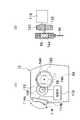
図3は、牽引機構部の構成を示した斜視図である。 FIG. 3 is a perspective view showing the configuration of the traction mechanism section.
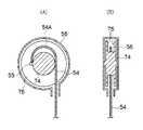
同図に示す牽引機構部は、ワイヤ(第1のワイヤ)46から操作レバー40に向けて、密着コイルばね固定部50、長さ調整部材52、牽引ワイヤ(第2のワイヤ)54、プーリハウジング56、ウォームホイール58、ウォーム60、平歯車62、及び歯車64から構成される。 The traction mechanism shown in the figure is directed from the wire (first wire) 46 toward the
ウォームホイール58とウォーム60とによってウォームギヤが構成され、このウォームギヤ、平歯車62、及び歯車64によって減速機構部が構成されている。なお、減速機構部は、ギヤからなる構成に限定されず、チェーン、ベルトによる減速機構部であってもよい。 The
図3において密着コイルばね44は図示していないが、前述の如く密着コイルばね44の他端は、筒状の密着コイルばね固定部50にロウ付け等で固定される。ワイヤ46の端部は、密着コイルばね固定部50に挿通され、長さ調整部材52を介して牽引ワイヤ54に連結されている。 Although the
長さ調整部材52は、経時によりワイヤ46が伸びてワイヤ46の余長が増加し、初期の可撓性可変性能が劣化した際に性能を初期状態に戻すために、可撓性可変側のワイヤ46と牽引機構部側の牽引ワイヤ54との接続部に設けられたものである。 The
長さ調整部材52は図4の(A)、(B)に示すように、筒状の雄ねじ66とスリーブナット68等から構成される。ワイヤ46は雄ねじ66に挿入され、その端部には抜け止め部材であるカシメ玉70が固着されている。一方、牽引ワイヤ54はスリーブナット68に挿入され、その端部には抜け止め部材であるカシメ玉72が固着されている。図4(A)に示すように雄ねじ66とスリーブナット68とを螺合させ、その螺合量を調整することにより、ワイヤ46の長さを調節することができる。なお、スリーブナット68は、ワイヤ46の牽引弛緩動作によって摺動するが、その軌道が不安定となりワイヤ46に不慮の力がかかることによる断線を防止するために、前記摺動を案内するスリーブガイド(不図示)を設け、ワイヤ46の牽引弛緩軌道に沿って動作するようにすることが好ましい。また、ワイヤ46と雄ねじ66、ワイヤ54とスリーブナット68のそれぞれの接続部は、剛性が急激に変化するためにワイヤ46、54に断線が発生しやすく、これを防止するために、ゴム管などの折れ止め部材を設けることが好ましい。 As shown in FIGS. 4A and 4B, the
図3に示したプーリハウジング56には、図5の(A)、(B)に示すように、ワイヤ54を牽引、弛緩するプーリ74が回転自在に設けられている。ワイヤ54は、その端点55がプーリ74に固定される。このプーリ74は、対向するワイヤガイド壁76、76の間隔がワイヤ54の直径以上に設定されている。また、ワイヤ脱落防止部材であるワイヤハウジング56は、ワイヤガイド壁76、76に対して、ワイヤ54の直径以下の隙間で近接配置されている。 As shown in FIGS. 5A and 5B, the
この構成によれば、ワイヤガイド壁76、76によってワイヤ54をプーリ74に確実に巻き取り、巻き戻すことができ、また、ワイヤハウジング56によってワイヤ54の余長部54Aが長くなってもワイヤハウジング56によって余長部54Aがプーリ74から脱落することを防止できる。 According to this configuration, the
プーリ74は、同軸で図3に示したウォームホイール58と連結され、このウォームホイール58はウォーム60に噛合されている。ウォーム60には、同軸で平歯車62が連結され、この平歯車62は、操作レバー40と同軸上に連結された歯車64に噛合されている。 The
ウォーム60のねじれ角は安息角(摩擦角)よりも小さくされており、これによって、ウォームホイール58からウォーム60への逆駆動が阻止されて、自己制動力が図5のプーリ74に与えられている。更に、前記減速機構部の減速比は例えば、50:1に設定されており、操作レバー40の操作力に対して50倍のトルクがプーリ74に伝達されるようになっている。これにより、数十キロに達するワイヤ牽引力を、より小さい操作力に軽減できるので、操作レバー40を指で容易に操作することができる。 The twist angle of the
すなわち、実施の形態の牽引機構部によれば、操作レバー40の小ストロークの繰り返し回動操作によってプーリ74に駆動を与えることができる。この牽引機構部では、減速機構部を介してプーリ74を回動させるため、操作レバー40の操作量は、特許文献1の操作レバーよりも増加するが、その減速比に相当するトルクを得ることができるので、ワイヤ46の牽引操作力を軽減できる。よって、施術者の指で操作レバー40を容易に操作することができる。また、減速機構部を使用することにより、操作レバーの1ストロークの回動でワイヤを牽引する特許文献1の牽引機構部よりも機構部が大型にならず、また、操作レバー40も特許文献1の操作レバーよりも小型で済むので、牽引機構部を小型化することができる。更に、牽引されたワイヤ46は、ウォームギヤの自己制動力によってプーリ74に巻き上げられた状態を保持するので、軟性部24の可撓性を容易に保持することができる。 That is, according to the traction mechanism unit of the embodiment, the
施術者によって操作レバー40が回動操作されると、操作レバー40に連結された歯車64が駆動し、これによって平歯車62が駆動される。その結果、ウォーム60及びウォームホイール58が駆動し、プーリ74が回動してワイヤ46がワイヤ54を介して牽引、弛緩される。そして、ワイヤ46の先端は、図2の如く密着コイルばね44の先端部に固定され、また密着コイルばね44の他端は、図3の如く密着コイルばね固定部50に固定されているため、ワイヤ46が牽引されると、密着コイルばね44は、プーリ50側に引っ張られて、密着コイルばね固定部材50との間で圧縮されて、その硬度を増す。 When the operating
ところで、操作レバー40は、図3に破線で示したように、上方向と下方向に操作可能に構成されている。 By the way, the
操作レバー40を上方向に操作すると、歯車64、平歯車62、ウォーム60、及びウォームホイール58を介してプーリ74がワイヤ54を巻き上げる方向に回動する。これにより、ワイヤ46が牽引されて密着コイルばね44が圧縮されるので、密着コイルばね44の硬度が増して軟性部24の可撓性が硬くなる。 When the
また、操作レバー40を下方向に操作すると、歯車64、平歯車62、ウォーム60、及びウォームホイール58を介してプーリ74がワイヤ54を巻き戻す方向に回動する。これにより、ワイヤ46が弛緩されて密着コイルばね44の圧縮が解除されるので、密着コイルばね44の硬度が減少して軟性部24の可撓性が軟らかくなる。 Further, when the
ここで、挿入部14(軟性部24)が湾曲すると密着コイルばね44も湾曲して長さが長くなる。そのため、操作レバー40を操作しなくとも、ワイヤ54は密着コイルばね44に対して相対的にプーリ50側に引き込まれるため、密着コイルばね44の可撓性が硬くなってしまう。そこで、この現象を防止するために、図5中符号54Aで示すように、ワイヤ54に余長部(初期たるみ)54Aを持たせている。 Here, when the insertion portion 14 (soft portion 24) is curved, the
また、施術者が操作レバー40を操作して軟性部24の可撓性を硬くしているときに、施術者が操作レバー40から手指を離しても、ウォームホイール58とウォーム60との歯面の摩擦力によって、すなわち、自己制動力によってウォームホイール58がその位置で固定される。このようにウォームホイール58の回動を制動することにより、プーリ74を任意の位置で固定でき、ワイヤ46の牽引状態を保持することができる。 Further, when the practitioner operates the
以上の如く、実施の形態の内視鏡10によれば、ワイヤ46を牽引し、弛緩するプーリ74と、プーリ74に回転駆動力を与えるとともにプーリ74に自己制動力を与えるウォームギヤを有する減速機構部とによって牽引機構部を構成したので、牽引機構部の小型化を図るとともにワイヤ46の牽引操作力を低減することができる。 As described above, according to the
次に、操作レバー40と減速機構部とを接続する一方向クラッチの基本機能について説明する。 Next, the basic function of the one-way clutch that connects the
一方向クラッチは、プーリ74によるワイヤ46の牽引、及びプーリ74によるワイヤ46の弛緩を選択的に操作する。このため、一方向クラッチは、操作レバー40の往路方向の回動で減速機構部に動力伝達し、操作レバー40の復路方向の回動で減速機構部に対して操作レバー40を空回りさせ機能を備える。 The one-way clutch selectively manipulates the pulling of the
したがって、ワイヤ46を牽引する場合、操作レバー40を往路方向に回動させると、その回動操作力が一方向クラッチを介して減速機構部に伝達されるので、ワイヤ46がプーリ74に牽引される。そして、操作レバー40を復路方向に回動させると、操作レバー40は一方向クラッチの作用によって減速機構部に対して空回りする。よって、減速機構部に動力が伝達されず、プーリ74は回転しない。 Therefore, when pulling the
すなわち、操作レバー40を往路方向と復路方向とに繰り返し回動させることにより、ワイヤ46がプーリ76に牽引されていく。また、操作レバー40の復路方向の操作時には、プーリ74はウォームギヤの自己制動力によって回転しない。これにより、ワイヤ46は、プーリ74に巻き上げられた状態が保持されるので、施術者の指で保持する必要はなく、施術者の負担が軽減される。なお、ワイヤ46を弛緩する場合も基本的な機能は同一である。 That is, the
次に、図6、図7を参照して一方向クラッチ80の第1の実施例について説明する。 Next, a first embodiment of the one-way clutch 80 will be described with reference to FIGS.
同図に示す一方向クラッチ80は、牽引用ラッチばね82、弛緩用ラッチばね84、駆動板88、及び操作方向仕切り板90から構成される。 The one-way clutch 80 shown in the figure includes a
牽引用ラッチばね82と弛緩用ラッチばね84は、操作レバー40の円盤状基端部41に一体的に固着されるとともに、操作レバー40の回転軸40Aから異なる距離に配置されている。牽引用ラッチばね82は、操作レバー40によるワイヤ46の矢印Aで示す牽引方向のみ、駆動板88に動力を伝える板ばねであり、弛緩用ラッチばね84は、ワイヤ46の矢印Bで示す弛緩方向のみ、駆動板88に動力を伝える板ばねである。 The
駆動板88は、歯車64と同軸上に固定されており、牽引用ラッチばね82が動力伝達可能に係合する第1の突起92、92…が等間隔に形成されている。これらの第1の突起92、92…は、駆動板88の回転軸を中心に放射状に形成されており、牽引方向における牽引用ラッチばね82の往路方向の移動で、牽引用ラッチばね82に当接される当接面が駆動板88に対して略直角に形成されている。また、前記当接面に対向する面は傾斜面であり、牽引方向における牽引用ラッチばね82の復路方向の移動で牽引用ラッチばね82が前記傾斜面に乗り上げて空回りするようになっている。 The
また、駆動板88には、弛緩用ラッチばね84が動力伝達可能に係合する第2の突起94、94…が等間隔に形成されている。これらの第2の突起94、94…は、駆動板88の回転軸を中心に放射状に形成されており、弛緩方向における弛緩用ラッチばね84の往路方向の移動で、弛緩用ラッチばね84に当接される当接面が駆動板88に対して略直角に形成されている。また、前記当接面に対向する面は傾斜面であり、弛緩方向における弛緩用ラッチばね84の復路方向の移動で弛緩用ラッチばね84が前記傾斜面に乗り上げて空回りするようになっている。 Further, the driving
操作方向仕切り板90は、手元操作部12に回動不能に固定されている。この操作方向仕切り板90には、牽引用ラッチばね82を貫通させて牽引用ラッチばね82の牽引方向の移動範囲を規制する第1の窓96が開口されるとともに、弛緩用ラッチばね84を貫通させて弛緩用ラッチばね84の弛緩方向の移動範囲を規制する第2の窓98が開口されている。第1の窓96、及び第2の窓98は、操作レバー40の回転軸40Aを中心とした同心円上に沿って開口されている。 The operation
また、操作レバー40は、図6の一点鎖線で示す基準位置Pに対して矢印Aで示す牽引方向の所定の回動範囲が牽引用操作範囲に設定される。また、操作レバー40は、基準位置Pに対して矢印Bで示す弛緩方向の所定の回動範囲が弛緩用操作範囲に設定される。そして、牽引用ラッチばね82は、前記牽引用操作範囲においてのみ、操作方向仕切り板90の第1の窓96を介して駆動板88の第1の突起92に係合され、また、弛緩用ラッチばね84は、前記弛緩用操作範囲においてのみ、操作方向仕切り板90の第2の窓98を介して駆動板88の第2の突起94に係合される。すなわち、第1の窓96によって牽引用操作範囲が設定され、第2の窓98によって弛緩用操作範囲が設定されている。 In addition, the
この一方向クラッチ80によれば、第1の窓96によって制限された牽引用操作範囲において、操作レバー40を矢印Aで示すワイヤ牽引方向(往路方向)に回動させると、牽引用ラッチばね82が第1の窓96から第1の突起92に係合していることから、駆動板88が回動され、その回動力が歯車64を有する減速機構部を介してプーリ74に伝達され、ワイヤ46がプーリ74に牽引される。この時、弛緩用ラッチばね84は、操作方向仕切り板90に当接されて第2の突起94に係合されていないため、弛緩用ラッチばね84は駆動板88に対して空回りする。 According to the one-way clutch 80, when the
そして、操作レバー40を牽引用操作範囲において復路方向に回動させると、牽引用ラッチばね82が第1の突起92の傾斜面に乗り上げて空回りする。よって、操作レバー40の前記復路方向での回動では、プーリ74に動力は伝達されない。 When the
そして、操作レバー40を往路方向に再び回動させると、前述の如く駆動板88が回動するので、プーリ74に動力が伝達されてワイヤ46がプーリ74に牽引される。このように操作レバー40を牽引用操作範囲において繰り返し回動させることにより、ワイヤ46がプーリ74に徐々に牽引されていく。この場合、操作レバー40の操作量は増えるが、減速機構部によって軽い操作力でワイヤ46を牽引することができる。 When the
次に、ワイヤ46を弛緩させる場合には、第2の窓98によって制限された弛緩用操作範囲において、操作レバー40を矢印Bで示すワイヤ弛緩方向(往路方向)に回動させると、弛緩用ラッチばね84が第2の窓98から第2の突起94に係合していることから、駆動板88が先とは逆方向に回動され、その回動力が歯車64を有する減速機構部を介してプーリ74に伝達され、ワイヤ46がプーリ74から巻き戻されて弛緩される。この時、牽引用ラッチばね82は、操作方向仕切り板90に当接されて第1の突起92に係合されていないため、牽引用ラッチばね82は駆動板88に対して空回りする。 Next, when the
そして、操作レバー40を弛緩用操作範囲において復路方向に回動させると、弛緩用ラッチばね84が第2の突起94の傾斜面に乗り上げて空回りする。よって、操作レバー40の前記復路方向での回動では、プーリ74に動力は伝達されない。 Then, when the
そして、操作レバー40を往路方向に再び回動させることにより、前述の如く駆動板88が回動するので、ワイヤ46がプーリ74から巻き戻されて弛緩される。このように操作レバー40を弛緩用操作範囲において繰り返し回動させることにより、ワイヤ46が徐々に弛緩されていく。 Then, by rotating the
以上の如く、第1の窓96、第2の窓98を使用して操作レバー40の回動範囲を規制することにより、操作レバー40による牽引、弛緩操作を安定して行うことができる。 As described above, by using the
次に、図8の(A)、(B)を参照して一方向クラッチ100の第2の実施例について説明する。 Next, a second embodiment of the one-way clutch 100 will be described with reference to FIGS.
同図に示す一方向クラッチ100は、牽引操作用の一方向クラッチ102と弛緩操作用の一方向クラッチ104とを有する。また、操作レバー106は、ワイヤ46を牽引する第1のレバー108と、ワイヤ46を弛緩させる第2のレバー110とを備え、第1のレバー108は、一方向クラッチ102を介して歯車64に連結され、第2のレバー110は、一方向クラッチ104を介して歯車64に連結されている。 The one-way clutch 100 shown in the figure has a one-
このレバー構成によれば、第1のレバー108を矢印Aで示す牽引方向に回動操作すると、ワイヤ46が牽引され、この時、第2のレバー110は歯車64に対して空回りする。また、第2のレバー110を矢印Bで示す弛緩方向に回動操作してワイヤ46を弛緩する場合には、第1のレバー108は歯車64に対して空回りする。 According to this lever configuration, when the
このレバー構成においても、第1及び第2のレバー108、110による往路方向の繰り替えし回動操作によってワイヤ46が牽引されるとともに弛緩される。 Also in this lever configuration, the
上述した実施の形態では、減速機構部を操作レバーによって回動操作する例について述べたが、図9、図10に示すようにモータによって減速機構部に動力を与える構造であってもよい。 In the above-described embodiment, the example in which the speed reduction mechanism portion is rotated by the operation lever has been described. However, as shown in FIGS. 9 and 10, a structure in which power is supplied to the speed reduction mechanism portion by a motor may be used.
図9の(A)は、手元操作部12の上部を拡大した断面図であり、図9の(B)は、牽引機構部を、図9の(A)の右側から見た側面図である。 9A is an enlarged cross-sectional view of the upper portion of the
同図に示す第1の電動ワイヤ牽引構造は、前述した手動方式と同様に、ワイヤ54を牽引、弛緩するプーリ74、プーリ74と同軸に固定されたウォームホイール58、ウォームホイール58を駆動するウォーム60、ウォーム60と同軸に固定された平歯車62、平歯車62に噛合された歯車64を有し、歯車64の軸にモータ112の出力軸が連結されている。 The first electric wire pulling structure shown in the figure is similar to the manual method described above, the
なお、モータ112は、特に限定されるものではなく、例えば、DCモータ、ステップモータあるいはサーボモータ等を用いることができる。また、このモータ112は、軟性部26の密着コイルばね44の硬度を決定する硬度位置機能を含んでいるものとする。また、密着コイルばね44の硬度をある状態で保持する自己制動力は、手動の場合と同じく、ウォームギヤが有している。 The
モータ112は、シーソレバー(操作部材)114の動作信号が出力される制御系116によって制御される。シーソレバー114は、手動方式の操作レバー40と同様、手元操作部12の上部の左手(例えば親指)のみで操作可能な位置に設置されている。シーソレバー114のレバー114Aを押すと、その信号が制御系116に出力され、制御系は前記信号に基づき、モータ112を正転させる。これによって、ワイヤ54がプーリ74に牽引されていき、軟性部24の可撓性が硬くなる。また、シーソレバー114のレバー114Bを押すと、その信号が制御系116に出力され、制御系は前記信号に基づき、モータ112を逆転させる。これによって、ワイヤ54がプーリ74から巻き戻されていくので、軟性部24の可撓性が柔らかくなる。本例では、操作部材としてシーソレバー114を例示したが、これに限定されるものではなく、片手の指で操作できるものであれば、どのような形式の操作部材であってもよい。 The
次に、電動でワイヤ54を牽引する第2の電動ワイヤ牽引構造を示す。 Next, a second electric wire pulling structure that pulls the
図10の(A)は、手元操作部12上部を拡大した断面図であり、図10の(B)は、ワイヤ牽引部を右側から見た側面図である。 FIG. 10A is an enlarged cross-sectional view of the upper part of the
図10に示す第2の電動ワイヤ牽引構造は、ワイヤ54を牽引するプーリ74Aをモータ118で直接駆動するものである。プーリ74Aは、モータ118によって直接駆動されるため、今までの例におけるプーリ74よりもその径が大きくなっている。プーリ74Aには同軸で平歯車120が連結されており、この平歯車120に歯車122が噛合され、この歯車122にモータ118の出力軸が連結されている。 In the second electric wire pulling structure shown in FIG. 10, a
モータ118は、前の例と同様に、特に限定されるものではなく、DCモータ、ステップモータあるいはサーボモータ等を用いることができる。ただ、この例では、ウォームギヤが用いられていないので、モータ118はブレーキ機能を有することが好ましい。また、同様にモータ118は、シーソレバー114の操作に基づき制御系116を介して制御される。 As with the previous example, the
なお、ワイヤ牽引部に電動モータ等を用いた場合には、図9及び図10に示した手元操作部12の上部を、モジュール単体としてシールドする。これにより、電磁ノイズ等のCHAケーブルへの悪影響を最小限に抑えることができる。 When an electric motor or the like is used for the wire pulling unit, the upper part of the
以上、本発明に係る内視鏡及び可撓性調整装置について詳細に説明したが、本発明は、以上の例には限定されず、本発明の要旨を逸脱しない範囲において、各種の改良や変形を行ってもよいのはもちろんである。 Although the endoscope and the flexibility adjusting device according to the present invention have been described in detail above, the present invention is not limited to the above examples, and various improvements and modifications can be made without departing from the gist of the present invention. Of course, you may also do.
10…内視鏡、12…手元操作部、14…挿入部、16…ユニバーサルケーブル、22…先端硬質部、24…湾曲部、26…軟性部、30…アングルノブ、32…送気・送水ボタン、34…吸引ボタン、36…鉗子挿入口、40…操作レバー、42…湾曲駒、44…密着コイルばね、46…ワイヤ、50…密着コイルばね固定部、52…長さ調整部材、54…牽引ワイヤ、56…プーリハウジング、58…ウォームホイール、60…ウォーム、62…平歯車、64…歯車、66…雄ねじ、68…スリーブナット、70…カシメ玉、72…カシメ玉、74…プーリ、76…ワイヤガイド壁、80…一方向クラッチ、82…牽引用ラッチばね、84…弛緩用ラッチばね、88…駆動板、90…操作方向仕切り板、92…第1の突起、94…第2の突起、96…第1の窓、98…第2の窓、100…一方向クラッチ、102…牽引操作用の一方向クラッチ、104…弛緩操作用の一方向クラッチ、106…操作レバー、108…第1のレバー、110…第2のレバー、112…モータ、114…シーソレバー、116…制御系、118…モータ、120…平歯車、122…歯車 DESCRIPTION OF
Claims (10)
Translated fromJapanese前記軟性部の先端部側に一端が固定されるとともに他端が前記挿入部の基端部又は前記手元操作部側に固定され、伸縮により可撓性が変化する可撓性可変部材と、
前記可撓性可変部材に挿通され、一端が前記軟性部の前記先端側に固定されるとともに他端が前記手元操作部に設けられた牽引機構部に連結されたワイヤとを有し、
前記牽引機構部は、
前記ワイヤの他端が巻回されるプーリと、
前記プーリに回転駆動力を与えるとともに前記プーリに自己制動力を与えるウォームギアを有する減速機構部と、を備えることを特徴とする内視鏡。An endoscope comprising a hand operation part and an insertion part having a proximal end connected to the hand operation part, wherein the insertion part includes a soft part having a proximal end connected to the hand operation part, In an endoscope comprising a curved portion having a proximal end connected to the distal end of the flexible portion, and a distal hard portion having a proximal end connected to the distal end of the curved portion,
A flexible variable member having one end fixed to the distal end side of the soft portion and the other end fixed to the proximal end portion of the insertion portion or the hand operation portion side, and the flexibility changes by expansion and contraction;
A wire inserted through the flexible variable member, having one end fixed to the distal end side of the soft portion and the other end connected to a traction mechanism provided in the hand operation portion;
The traction mechanism is
A pulley around which the other end of the wire is wound;
An endoscope comprising: a reduction mechanism having a worm gear that applies a rotational driving force to the pulley and a self-braking force to the pulley.
前記一方向クラッチは、前記プーリによる前記ワイヤの牽引、及び前記プーリによる前記ワイヤの弛緩を選択的に操作するために、前記操作レバーの往路方向の回動で前記減速機構部に動力伝達し、前記操作レバーの復路方向の回動で前記減速機構部に対して前記操作レバーを空回りさせる一方向クラッチである請求項2に記載の内視鏡。The deceleration mechanism and the operation lever are connected via a one-way clutch,
The one-way clutch transmits power to the speed reduction mechanism by rotating the operation lever in the forward direction in order to selectively operate pulling of the wire by the pulley and relaxation of the wire by the pulley. The endoscope according to claim 2, wherein the endoscope is a one-way clutch that idles the operation lever with respect to the speed reduction mechanism unit when the operation lever rotates in a backward direction.
前記ワイヤを牽引するための第1のレバーと、
前記ワイヤを弛緩させるための第2のレバーと、を備え、
前記第1のレバーと前記第2のレバーは前記一方向クラッチを各々備える請求項3に記載の内視鏡。The operation lever is
A first lever for pulling the wire;
A second lever for relaxing the wire,
The endoscope according to claim 3, wherein the first lever and the second lever each include the one-way clutch.
前記一方向クラッチは、
前記操作レバーと一体的に設けられるとともに該操作レバーの回転軸から異なる距離に配置され、前記操作レバーによる前記ワイヤの牽引方向にのみ動力を伝える牽引用ラッチばね、及び前記ワイヤの弛緩方向にのみ動力を伝える弛緩用ラッチばねと、
前記減速機構部に連結されるとともに、前記牽引用ラッチばねが動力伝達可能に係合する第1の突起、及び前記弛緩用ラッチばねが動力伝達可能に係合する第2の突起が異なる円周上に備えられた駆動板と、
を備える請求項2に記載の内視鏡。The deceleration mechanism and the operation lever are connected via a one-way clutch,
The one-way clutch is
A pulling latch spring that is provided integrally with the operation lever and disposed at different distances from the rotation axis of the operation lever and transmits power only in the pulling direction of the wire by the operating lever, and only in the loosening direction of the wire A latch spring for transmitting power,
The first protrusions that are coupled to the speed reduction mechanism and engage with the traction latch spring so as to be able to transmit power, and the second protrusions that engage with the relaxation latch spring so that power can be transmitted are different. A drive plate provided on top;
The endoscope according to claim 2, comprising:
該操作方向仕切り板は、前記牽引用ラッチばねを貫通させて該牽引用ラッチばねの移動範囲を規制する第1の窓、及び前記弛緩用ラッチばねを貫通させて該弛緩用ラッチばねの移動範囲を規制する第2の窓が開口される請求項5に記載の内視鏡。The one-way clutch has an operation direction partition plate;
The operation direction partition plate passes through the traction latch spring to restrict the movement range of the traction latch spring, and the movement range of the relaxation latch spring through the relaxation latch spring. The endoscope according to claim 5, wherein the second window that regulates is opened.
前記牽引用ラッチばねは、前記牽引用操作範囲においてのみ、前記操作方向仕切り板の前記第1の窓を介して前記駆動板の前記第1の突起に係合され、
前記弛緩用ラッチばねは、前記弛緩用操作範囲においてのみ、前記操作方向仕切り板の前記第2の窓を介して前記駆動板の前記第2の突起に係合される請求項6に記載の内視鏡。The operation lever has a predetermined rotation range in a pulling direction with respect to a reference position as a pulling operation range, and a predetermined rotation in a relaxation direction opposite to the pulling direction with respect to the reference position. The range is set to the operating range for relaxation,
The traction latch spring is engaged with the first protrusion of the drive plate via the first window of the operation direction partition plate only in the traction operation range,
The inner spring according to claim 6, wherein the relaxation latch spring is engaged with the second protrusion of the drive plate via the second window of the operation direction partition plate only in the operation range for relaxation. Endoscope.
前記電動モータは、制御部によって回転方向が制御され、
前記制御部は、前記手元操作部に設けられた操作部材の操作に基づき前記電動モータの回転方向を制御する請求項1に記載の内視鏡。An output shaft of an electric motor is connected to the speed reduction mechanism,
The rotation direction of the electric motor is controlled by the control unit,
The endoscope according to claim 1, wherein the control unit controls a rotation direction of the electric motor based on an operation of an operation member provided in the hand operation unit.
前記第1のワイヤと前記第2のワイヤとは、前記ワイヤの長さを調整する調整部材を介して連結される請求項1〜9のいずれかに記載の内視鏡。The wire is composed of a first wire inserted through the flexible variable member, and a second wire wound around the pulley and positioned inside the hand operation unit,
The endoscope according to any one of claims 1 to 9, wherein the first wire and the second wire are connected via an adjustment member that adjusts a length of the wire.
Priority Applications (2)
| Application Number | Priority Date | Filing Date | Title |
|---|---|---|---|
| JP2010203392AJP2012055569A (en) | 2010-09-10 | 2010-09-10 | Endoscope |
| CN 201110263421CN102397051A (en) | 2010-09-10 | 2011-09-07 | Endoscope |
Applications Claiming Priority (1)
| Application Number | Priority Date | Filing Date | Title |
|---|---|---|---|
| JP2010203392AJP2012055569A (en) | 2010-09-10 | 2010-09-10 | Endoscope |
Publications (1)
| Publication Number | Publication Date |
|---|---|
| JP2012055569Atrue JP2012055569A (en) | 2012-03-22 |
Family
ID=45879966
Family Applications (1)
| Application Number | Title | Priority Date | Filing Date |
|---|---|---|---|
| JP2010203392APendingJP2012055569A (en) | 2010-09-10 | 2010-09-10 | Endoscope |
Country Status (2)
| Country | Link |
|---|---|
| JP (1) | JP2012055569A (en) |
| CN (1) | CN102397051A (en) |
Cited By (2)
| Publication number | Priority date | Publication date | Assignee | Title |
|---|---|---|---|---|
| JP2014191167A (en)* | 2013-03-27 | 2014-10-06 | Kurimoto Ltd | Pipe inside inspection apparatus |
| WO2015098236A1 (en)* | 2013-12-24 | 2015-07-02 | オリンパス株式会社 | Endoscope |
Families Citing this family (5)
| Publication number | Priority date | Publication date | Assignee | Title |
|---|---|---|---|---|
| CN103690139B (en)* | 2013-12-25 | 2017-01-25 | 武汉佑康科技有限公司 | Endoscope with angle adjusting function |
| CN109975971B (en)* | 2017-12-27 | 2021-09-07 | 上海微创医疗机器人(集团)股份有限公司 | Endoscope power locking and adjusting mechanism and endoscope holding system |
| CN109896358B (en)* | 2019-04-19 | 2024-02-23 | 上海熠达光电科技有限公司 | Insertion tube winding device |
| CN112205951A (en)* | 2020-10-12 | 2021-01-12 | 武汉佑康科技有限公司 | Directional bent endoscope catheter |
| CN117547215A (en)* | 2024-01-08 | 2024-02-13 | 江苏永乐医疗科技有限公司 | Anesthesia video laryngoscope and light source |
- 2010
- 2010-09-10JPJP2010203392Apatent/JP2012055569A/enactivePending
- 2011
- 2011-09-07CNCN 201110263421patent/CN102397051A/enactivePending
Cited By (2)
| Publication number | Priority date | Publication date | Assignee | Title |
|---|---|---|---|---|
| JP2014191167A (en)* | 2013-03-27 | 2014-10-06 | Kurimoto Ltd | Pipe inside inspection apparatus |
| WO2015098236A1 (en)* | 2013-12-24 | 2015-07-02 | オリンパス株式会社 | Endoscope |
Also Published As
| Publication number | Publication date |
|---|---|
| CN102397051A (en) | 2012-04-04 |
Similar Documents
| Publication | Publication Date | Title |
|---|---|---|
| JP2012055569A (en) | Endoscope | |
| JP5675223B2 (en) | Endoscope and hardness adjustment device | |
| JP5301104B2 (en) | Medical device with meshing mechanism | |
| JP5124629B2 (en) | Endoscope and hardness adjustment device | |
| CN1923151B (en) | Medical device | |
| JP2009136566A (en) | Holding cable, observation apparatus and endoscope apparatus having the holding cable | |
| US20020116011A1 (en) | Endoscopic suturing device | |
| US20110021871A1 (en) | Laparoscopic surgical instrument | |
| US11839355B2 (en) | Endoscope | |
| US20140058363A1 (en) | Endoscopic Surgical Instrument | |
| JP2012055568A (en) | Endoscope | |
| JP2012081010A (en) | Endoscope and hardness adjusting device | |
| JP2008018233A (en) | Rotary actuator for endoscope apparatus | |
| JP6280848B2 (en) | Medical instruments | |
| JP6427673B2 (en) | manipulator | |
| CN114680954B (en) | Adjustable curved medical device | |
| JP2013027466A (en) | Medical apparatus | |
| CN116271428B (en) | A bending control device and adjustable bending sheath | |
| JP2012081011A (en) | Endoscope and hardness adjusting device | |
| WO2016190273A1 (en) | Medical manipulator | |
| CN117503027A (en) | Endoscope and operating handle thereof | |
| EP2401952B1 (en) | Endoscope apparatus | |
| JP6063773B2 (en) | Insertion device | |
| EP3834703A1 (en) | Endoscope | |
| US20170209164A1 (en) | Medical treatment tool |