JP2012048829A - Composite cable - Google Patents
Composite cableDownload PDFInfo
- Publication number
- JP2012048829A JP2012048829AJP2010186855AJP2010186855AJP2012048829AJP 2012048829 AJP2012048829 AJP 2012048829AJP 2010186855 AJP2010186855 AJP 2010186855AJP 2010186855 AJP2010186855 AJP 2010186855AJP 2012048829 AJP2012048829 AJP 2012048829A
- Authority
- JP
- Japan
- Prior art keywords
- optical fiber
- composite cable
- electric wire
- optical
- spirally wound
- Prior art date
- Legal status (The legal status is an assumption and is not a legal conclusion. Google has not performed a legal analysis and makes no representation as to the accuracy of the status listed.)
- Pending
Links
Images


Landscapes
- Communication Cables (AREA)
Abstract
Translated fromJapaneseDescription
Translated fromJapanese本発明は、複合ケーブルに関し、特に、優れた屈曲性を有すると共に、屈曲される場所における光信号の劣化を抑制することができる複合ケーブルに関する。 The present invention relates to a composite cable, and more particularly to a composite cable that has excellent flexibility and can suppress deterioration of an optical signal at a bent place.
光信号の伝送を行う光ファイバと、電気信号や電力の伝送を行う電線とが組み合わされた複合ケーブルが知られている。このような複合ケーブルは、産業機械や、映像機器等に用いられており、例えば、複合ケーブルが映像機器に用いられる場合、画像情報等の大容量の信号が光ファイバにより伝送され、音声やテキスト情報等が電線により伝送される。 A composite cable in which an optical fiber that transmits an optical signal and an electric wire that transmits an electric signal or electric power are combined is known. Such composite cables are used in industrial machines, video equipment, and the like. For example, when composite cables are used in video equipment, large-capacity signals such as image information are transmitted by optical fiber, and are used for voice and text. Information etc. are transmitted by electric wires.
下記特許文献1には、このような複合ケーブルが記載されている。この複合ケーブルにおいては、中心に1つの光ファイバが直線状に設けられており、その光ファイバの外周面を被覆する外部被覆層が設けられて、その外部被覆層の外周面上に複数の電線が設けられている。この電線は、外部被覆層の外周面上に螺旋状に巻かれている。このように電線が螺旋状に巻かれることにより、この複合ケーブルは、屈曲性に優れるとされている。
しかし、上記特許文献1に記載の複合ケーブルにおいては、光信号を伝送する光ファイバが直線状に設けられている。従って、この複合ケーブルは、屈曲性に優れるものの屈曲する場合に、光ファイバの屈曲する部分に応力が集中し、この応力の集中により屈折率が変化して、光信号が劣化する虞がある。 However, in the composite cable described in
そこで、本発明は、優れた屈曲性を有すると共に、屈曲される場所における光信号の劣化を抑制することができる複合ケーブルを提供することを目的とする。 Therefore, an object of the present invention is to provide a composite cable that has excellent flexibility and can suppress deterioration of an optical signal at a bent place.
上記課題を解決するため、本発明の複合ケーブルは、直線状に配置される第1光ファイバと、前記第1光ファイバに螺旋状に巻かれる少なくとも1本の第2光ファイバと、を有する光ファイバ束と、前記光ファイバ束に螺旋状に巻かれる少なくとも1本の電線と、を備えることを特徴とするものである。 In order to solve the above problems, a composite cable of the present invention is a light having a first optical fiber arranged in a straight line and at least one second optical fiber wound spirally around the first optical fiber. It comprises a fiber bundle and at least one electric wire spirally wound around the optical fiber bundle.
このような複合ケーブルによれば、電線により電力や電気信号を伝送することができると共に、少なくとも第2光ファイバにより光信号を伝送することができる。また、第2光ファイバ、及び、電線は、それぞれ第1光ファイバ、及び、光ファイバ束に螺旋状に巻かれているので、第2光ファイバ、及び、電線は、複合ケーブルが屈曲する場所において、第2光ファイバや電線の長さ方向に僅かに位置ずれを起こす。こうして、複合ケーブルは、優れた屈曲性を有することができる。さらに、第2光ファイバが、位置ずれを起こすことにより、複合ケーブルが屈曲する場合に、第2光ファイバの一部に応力が集中することが抑制されて、第2光ファイバにより光信号を伝送させるときに、光信号が劣化することを抑制することができる。 According to such a composite cable, it is possible to transmit electric power and an electric signal through electric wires, and to transmit an optical signal through at least the second optical fiber. In addition, since the second optical fiber and the electric wire are spirally wound around the first optical fiber and the optical fiber bundle, respectively, the second optical fiber and the electric wire are in a place where the composite cable is bent. The position shifts slightly in the length direction of the second optical fiber or the electric wire. Thus, the composite cable can have excellent flexibility. Further, when the composite optical cable is bent due to the positional deviation of the second optical fiber, stress is suppressed from being concentrated on a part of the second optical fiber, and an optical signal is transmitted by the second optical fiber. It is possible to suppress the deterioration of the optical signal when it is performed.
また、上記複合ケーブルにおいて、前記光ファイバ束及び前記電線を覆うように、前記電線に螺旋状に巻かれるテープを更に備えることが好ましい。 Moreover, it is preferable that the composite cable further includes a tape spirally wound around the electric wire so as to cover the optical fiber bundle and the electric wire.
このような複合ケーブルによれば、テープにより電線や第2光ファイバがばらけてしまうことを防止することができる。そして、テープが螺旋状に巻かれているため、複合ケーブルの屈曲性が阻害されることを抑制することができる。 According to such a composite cable, it is possible to prevent the electric wire and the second optical fiber from being scattered by the tape. And since the tape is wound spirally, it can suppress that the flexibility of a composite cable is inhibited.
また、上記複合ケーブルにおいて、前記光ファイバ束を被覆する被覆層を更に備え、前記電線は、前記被覆層を介して前記光ファイバ束に螺旋状に巻かれることが好ましい。 Preferably, the composite cable further includes a coating layer that covers the optical fiber bundle, and the electric wire is spirally wound around the optical fiber bundle via the coating layer.
このような複合ケーブルによれば、被覆層により第2光ファイバが、第2光ファイバの横方向に位置ずれすることを防止して、第2光ファイバが偏在することを防止することができる。こうして第2光ファイバが偏在することにより一部の第2光ファイバに応力が集中することを防止することができる。 According to such a composite cable, the second optical fiber can be prevented from being displaced in the lateral direction of the second optical fiber by the coating layer, and the second optical fiber can be prevented from being unevenly distributed. In this way, it is possible to prevent stress from being concentrated on some of the second optical fibers due to the uneven distribution of the second optical fibers.
また、上記複合ケーブルにおいて、前記第1光ファイバと前記第2光ファイバとが、互いに同じ直径であり、前記第2光ファイバは6本であることが好ましい。 In the composite cable, it is preferable that the first optical fiber and the second optical fiber have the same diameter, and the number of the second optical fibers is six.
このような複合ケーブルによれば、第2光ファイバを細密充填して、光ファイバ束の直径を小さくすることができる。 According to such a composite cable, the diameter of the optical fiber bundle can be reduced by densely filling the second optical fiber.
また、上記複合ケーブルにおいて、前記第1光ファイバは、光信号を伝送しないダミーファイバであることが好ましい。 In the composite cable, the first optical fiber is preferably a dummy fiber that does not transmit an optical signal.
第2光ファイバは、第1光ファイバに螺旋状に巻かれるため、複合ケーブルの一定の長さに対して、互いに異なる長さとなる。従って、このような複合ケーブルによれば、第2光ファイバのみで光信号を伝送するため、光信号の伝送時間が異なることを防止することができる。 Since the second optical fiber is spirally wound around the first optical fiber, the second optical fiber has different lengths with respect to a certain length of the composite cable. Therefore, according to such a composite cable, since the optical signal is transmitted only by the second optical fiber, it is possible to prevent the transmission time of the optical signal from being different.
また、上記複合ケーブルにおいて、前記第2光ファイバが螺旋状に巻かれるピッチは、前記電線が螺旋状に巻かれるピッチよりも大きいことが好ましい。 In the composite cable, it is preferable that a pitch at which the second optical fiber is spirally wound is larger than a pitch at which the electric wire is spirally wound.
このような複合ケーブルによれば、第2光ファイバの曲率が高くなることを抑制することができ、第2光ファイバにより伝送される光信号の曲げ損失による劣化を抑制することができる。また、複合ケーブルの外周側に配置される電線は、複合ケーブルの屈曲による影響をより強く受けるので、電線が小さなピッチで巻かれることにより、複合ケーブルの屈曲性をより向上させることができる。なお、本明細書におけるピッチとは、光ファイバや電線が、螺旋状に1周巻かれる場合における、複合ケーブルの長さ方向に沿った距離を意味する。 According to such a composite cable, it is possible to suppress an increase in the curvature of the second optical fiber, and it is possible to suppress deterioration due to bending loss of an optical signal transmitted through the second optical fiber. Moreover, since the electric wire arrange | positioned at the outer peripheral side of a composite cable receives the influence by the bending of a composite cable more strongly, the flexibility of a composite cable can be improved more by winding an electric wire with a small pitch. In addition, the pitch in this specification means the distance along the length direction of a composite cable in case an optical fiber or an electric wire is wound once in a spiral.
また、前記第1光ファイバ及び前記第2光ファイバは、ガラス製のコア及びクラッドを有する光ファイバであることが好ましい。 The first optical fiber and the second optical fiber are preferably optical fibers having a glass core and cladding.
このように構成することにより、第1光ファイバ及び第2光ファイバの線膨張係数等の物性を等しくすることができる。従って、環境温度の変化により第1、第2光ファイバが伸縮しても、第2光ファイバに過度な応力がかかることを抑制でき、光信号が劣化することを抑制することができる。 By comprising in this way, physical properties, such as a linear expansion coefficient, of a 1st optical fiber and a 2nd optical fiber can be made equal. Therefore, even if the first and second optical fibers expand and contract due to a change in environmental temperature, it is possible to suppress excessive stress from being applied to the second optical fiber, and it is possible to suppress deterioration of the optical signal.
以上のように、本発明によれば、優れた屈曲性を有すると共に、屈曲される場所における光信号の劣化を抑制することができる複合ケーブルが提供される。 As described above, according to the present invention, there is provided a composite cable that has excellent flexibility and can suppress deterioration of an optical signal at a bent place.
以下、本発明に係る複合ケーブルの好適な実施形態について図面を参照しながら詳細に説明する。 Hereinafter, a preferred embodiment of a composite cable according to the present invention will be described in detail with reference to the drawings.
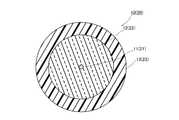
図1は、本発明の実施形態に係る複合ケーブル示す側面図であり、図2は、図1の複合ケーブルの長手方向に垂直な断面における構造の様子を示す図である。 FIG. 1 is a side view showing a composite cable according to an embodiment of the present invention, and FIG. 2 is a view showing a structure in a cross section perpendicular to the longitudinal direction of the composite cable of FIG.
図1、図2に示すように、複合ケーブル1は、1本の第1光ファイバ10と、第1光ファイバ10に巻かれる複数本の第2光ファイバ20とを有する光ファイバ束30と、光ファイバ束30を被覆する被覆層40と、被覆層40に螺旋状に巻かれる複数本の電線50と、電線50を覆うようにして、電線50に螺旋状に巻かれるテープ60と、テープ60を被覆するシース70とを主な構成として備える。 As shown in FIGS. 1 and 2, the
図3は、図1の第1、第2光ファイバ10、20の長手方向に垂直な断面における構造の様子を示す図である。図3に示すように、第1光ファイバ10は、コア11と、コア11の外周面を被覆するクラッド12と、クラッド12の外周面を被覆する保護層13とを主な構成として備え、第2光ファイバ20は、コア21と、コア21の外周面を被覆するクラッド22と、クラッド22の外周面を被覆する保護層23とを主な構成として備え、本実施形態においては、第1光ファイバ10と第2光ファイバ20とは、互いに同様の構成とされている。従って、以下、第1光ファイバ10の構造・材料について説明する。 FIG. 3 is a view showing a structure in a cross section perpendicular to the longitudinal direction of the first and second
クラッド12の屈折率は、コア11の屈折率よりも低くされており、コア11を光が伝播するように構成されている。また、光ファイバ10における各構成の大きさは、その用途により適切に選択されるため特に制限されるものではないが、例えば、コア11の直径は、4μm〜50μmとされ、クラッド12の外径は、100μm〜200μmとされ、保護層13の外径は、170μm〜350μmとされている。 The
また、コア11を構成する材料としては、例えば、屈折率を高くするドーパントが添加される石英等が挙げられる。このようなドーパントとしては、酸化ゲルマニウム(GeO2)や酸化アルミニウム(Al2O3)等が挙げられる。また、クラッド12を構成する材料としては、例えば、何らドーパントが添加されない石英や、フッ素(F)等の屈折率を下げるドーパントが添加される石英が挙げられる。また、保護層13を構成する材料としては、例えば、アクリレート等の紫外線硬化樹脂が挙げられる。Moreover, as a material which comprises the
また、第1光ファイバ10は、直線状に配置されている。この直線状に配置されるとは、複合ケーブル1の長手方向に沿って配置されることであり、複合ケーブル1が直線状にされる場合に、第1光ファイバ10も直線状になることを意味している。そして、この第1光ファイバ10の外周面上に、複数本の第2光ファイバ20が螺旋状に巻かれている。このように螺旋状に巻かれる第2光ファイバ20のピッチは、特に制限されるものではないが、本実施形態においては、約100mmとされている。 Moreover, the 1st
また、図2に示すように、本実施形態においては、第1光ファイバ10及び第2光ファイバ20の直径は同じとされており、第1光ファイバ10の外周面上に6本の第2光ファイバ20が螺旋状に巻かれている。このようにすることにより、第1光ファイバ10の外周面上に第2光ファイバ20を細密充填して、光ファイバ束30の直径を小さくすることができるため好ましい。 As shown in FIG. 2, in the present embodiment, the diameters of the first
こうして第1光ファイバ10の外周面上に第2光ファイバ20が螺旋状に巻かれることにより光ファイバ束30とされており、上述のように、光ファイバ束30は、被覆層40により被覆されている。被覆層40は、長手方向に垂直な断面における外形が円形とされ、例えば、押し出し成型により光ファイバ束30を被覆している。この被覆層40の直径は、特に制限されるものではないが、0.75mm〜2.0mmとされる。被覆層40の材料としては、特に制限されないが、例えば、ポリエチレン、ポリプロピレン等の樹脂を挙げることができる。 Thus, the second
図4は、電線50の長手方向に垂直な断面における構造の様子を示す図である。図4に示すように、電線50は、金属の撚り線から成る導線51と、導線51の外周を被覆する絶縁層52とを有している。この電線50の直径は、特に限定されないが、0.2mm〜2.0mmとされる。また、電線50の導線51の材料としては、導体であれば特に限定されないが、銅、鉄、ニッケル、アルミニウム等を挙げることができる。さらに絶縁層52の材料は、難燃性、耐水性、絶縁性等に優れた特性を有する材料が好ましい。このような材料としては、ポリエチレン、エチレン酢酸ビニル共重合体及びエチレンアクリル酸エチル共重合体などのエチレン系材料や、それらとポリプロピレン、エチレンプロピレンゴム、スチレン系エラストマなどのポリオレフィンをブレンドした複合樹脂をベースに、水酸化マグネシウム、水酸化アルミニウムなどの金属水酸化物又はリン酸エステルを添加してなるものやフッ素樹脂を挙げることができる。 FIG. 4 is a diagram illustrating a structure in a cross section perpendicular to the longitudinal direction of the
このような構成の複数の電線50が、上述のように被覆層40の外周面上に螺旋状に巻かれており、電線50が巻かれるピッチは、第2光ファイバ20が螺旋状に巻かれるピッチよりも小さくされることが好ましく、本実施形態においては、10mmとされている。また、この電線50が螺旋状に巻かれる方向は、図1に示すように第2光ファイバが巻かれる方向と同じ方向であることが、複合ケーブル1を屈曲させた際に、電線50と第2光ファイバ20とが同じ方向に位置ずれを起こすので、複合ケーブル1の屈曲性を向上させる観点から好ましい。 The plurality of
また、電線50は、テープ60により覆われている。テープ60は、樹脂、或いは、金属のテープであり、図1に示すように螺旋状に巻かれている。このテープ60を構成する樹脂としては、ポリエチレンテレフタレート等を挙げることができ、金属としては、アルミニウム、銅等を挙げることができる。なお、テープ60が螺旋状に巻かれる方向は、図1に示すように電線50が巻かれる方向と逆の方向であることが、複合ケーブル1を屈曲させた際に、電線が位置ずれしようとする方向と、テープが位置ずれしようとする方向とが、逆方向になるため、電線の位置ずれが大きくなりすぎてしまうことや、電線の位置ずれが元に戻らなくなってしまうことにより、電線がばらばらになることを防ぎ、複合ケーブル1の形状を維持できる観点から好ましい。なお、テープ60の電線50側の面には、接着剤が塗布されていても良い。 Further, the
テープ60の外周面上を被覆するシース70は、押し出し成型により形成されており、長手方向に垂直な断面における外形が円形とされている。このようなシース70の材料としては、電線50の絶縁層52と同様の材料を挙げることができる。 The
以上説明した複合ケーブル1においては、それぞれの電線50により、電気信号や電力の伝送を行うと共に、少なくとも第2光ファイバ20により、光信号の伝送を行う。この場合において、第1光ファイバ10をダミーファイバとして光信号の伝送を行わないことが好ましい。これは、第1光ファイバ10は、螺旋状に巻かれていないため、複合ケーブル1が屈曲するときに応力が集中することがあるためである。ただし、第1光ファイバ10により、光信号の伝送を行っても良い。 In the
以上説明したように、本実施形態の複合ケーブル1によれば、電線50により電力や電気信号を伝送することができると共に、少なくとも第2光ファイバ20により光信号を伝送することができる。また、複数本の第2光ファイバ20、及び、複数本の電線50は、それぞれ螺旋状に巻かれているので、第2ファイバ20、及び、電線50は、複合ケーブル1が屈曲する場合、複合ケーブル1が屈曲する場所において、僅かに長さ方向に位置ずれを起こす。つまり、複合ケーブル1が屈曲している部分において、第1光ファイバ10を基準として、内側に位置する第2光ファイバ外側に僅かに移動する。こうして、複合ケーブル1は、優れた屈曲性を有することができる。さらに、第2光ファイバ20が、第2光ファイバ20の長さ方向に位置ずれを起こすことにより、複合ケーブル1が屈曲する場合に、第2光ファイバ20の一部に応力が集中することが抑制される。そのため、第2光ファイバ20の一部の屈折率が変化することが抑制されて、第2光ファイバ20により光信号を伝送させるときに、光信号が劣化することを抑制することができる。 As described above, according to the
さらに、複合ケーブル1においては、テープ60により電線50や第2光ファイバ20がばらけてしまうことを防止することができる。そして、このテープ60は、螺旋状に巻かれているため、複合ケーブル1の屈曲性が阻害されることを抑制することができる。 Furthermore, in the
また更に、複合ケーブル1においては、複合ケーブル1が屈曲する場合において、被覆層40により第2光ファイバ20が、第2光ファイバ20の横方向に位置ずれすることを防止して、第2光ファイバ20が偏在することを防止することができる。こうして第2光ファイバ20が集まることにより一部の第2光ファイバ20に応力が集中することを防止することができる。 Furthermore, in the
そして、上述のように第1光ファイバ10がダミーファイバとされて、光信号が第2光ファイバ20のみにより伝送される場合においては、複合ケーブル1が屈曲するときに応力集中が抑制された第2光ファイバのみにより、光信号を伝送するため、光信号の劣化をより抑制することができる。また、第2光ファイバ20は、第1光ファイバ10に螺旋状に巻かれるため、複合ケーブル1の一定の長さに対して、互いに異なる長さとなる。従って、第1光ファイバ10をダミーファイバとして、第2光ファイバのみで光信号を伝送することにより、光信号の伝送時間が異なることを防止することができる。 In the case where the first
また、上述のように電線50が巻かれるピッチが、第2光ファイバ20が螺旋状に巻かれるピッチよりも小さい、つまり、第2光ファイバ20が螺旋状に巻かれるピッチが、電線50が螺旋状に巻かれるピッチよりも大きいことにより、第2光ファイバの曲率が高くなることを抑制することができる。従って、第2光ファイバ20により伝送される光信号の曲げ損失による劣化を抑制することができる。また、複合ケーブル1の外周側に配置される電線50は、複合ケーブル1の屈曲による影響をより強く受けるので、この電線50が小さなピッチで巻かれることにより、複合ケーブル1の屈曲性を向上させることができる。 Further, as described above, the pitch at which the
以上、本発明について、実施形態を例に説明したが、本発明はこれらに限定されるものではない。 As mentioned above, although this invention was demonstrated to the example for embodiment, this invention is not limited to these.
例えば、上記実施形態においては、第1、第2光ファイバ10、20のコア11、21、クラッド12、22は、ガラス製とされたが、本発明において、第1、第2光ファイバの少なくとも一方をプラスチック光ファイバ(POF)としても良い。 For example, in the above-described embodiment, the
また、第2光ファイバ20を1本として、第1光ファイバ10の外周面上に螺旋状に巻いても良く、電線50を一本として、螺旋状に巻いても良い。 Further, the second
また、被覆層40を、光ファイバ束30に対し、絶縁性のテープを螺旋状に巻くことで形成しても良い。 Further, the
本発明によれば、優れた屈曲性を有すると共に、屈曲される場所における光信号の劣化を抑制することができる複合ケーブルが提供される。 ADVANTAGE OF THE INVENTION According to this invention, while having the outstanding flexibility, the composite cable which can suppress deterioration of the optical signal in the place bent is provided.
1・・・複合ケーブル
10・・・第1光ファイバ
11・・・コア
12・・・クラッド
13・・・保護層
20・・・第2光ファイバ
21・・・コア
22・・・クラッド
23・・・保護層
30・・・光ファイバ束
40・・・被覆層
50・・・電線
51・・・導線
52・・・絶縁層
60・・・テープ
70・・・シースDESCRIPTION OF
Claims (7)
Translated fromJapanese前記光ファイバ束に螺旋状に巻かれる少なくとも1本の電線と、
を備える
ことを特徴とする複合ケーブル。An optical fiber bundle having a first optical fiber arranged linearly and at least one second optical fiber spirally wound around the first optical fiber;
At least one electric wire spirally wound around the optical fiber bundle;
A composite cable characterized by comprising:
前記電線は、前記被覆層を介して前記光ファイバ束に螺旋状に巻かれる
ことを特徴とする請求項1または2に記載の複合ケーブル。A coating layer for coating the optical fiber bundle;
The composite cable according to claim 1, wherein the electric wire is spirally wound around the optical fiber bundle through the coating layer.
前記第2光ファイバは6本である
ことを特徴とする請求項1〜3のいずれか1項に記載の複合ケーブル。The first optical fiber and the second optical fiber have the same diameter;
The composite cable according to claim 1, wherein the number of the second optical fibers is six.
Priority Applications (1)
| Application Number | Priority Date | Filing Date | Title |
|---|---|---|---|
| JP2010186855AJP2012048829A (en) | 2010-08-24 | 2010-08-24 | Composite cable |
Applications Claiming Priority (1)
| Application Number | Priority Date | Filing Date | Title |
|---|---|---|---|
| JP2010186855AJP2012048829A (en) | 2010-08-24 | 2010-08-24 | Composite cable |
Publications (1)
| Publication Number | Publication Date |
|---|---|
| JP2012048829Atrue JP2012048829A (en) | 2012-03-08 |
Family
ID=45903501
Family Applications (1)
| Application Number | Title | Priority Date | Filing Date |
|---|---|---|---|
| JP2010186855APendingJP2012048829A (en) | 2010-08-24 | 2010-08-24 | Composite cable |
Country Status (1)
| Country | Link |
|---|---|
| JP (1) | JP2012048829A (en) |
Cited By (3)
| Publication number | Priority date | Publication date | Assignee | Title |
|---|---|---|---|---|
| JP5273284B1 (en)* | 2012-09-20 | 2013-08-28 | 日立電線株式会社 | Photoelectric composite cable |
| JP2016100198A (en)* | 2014-11-21 | 2016-05-30 | 日立金属株式会社 | Opto-electric composite cable |
| JP2017027716A (en)* | 2015-07-21 | 2017-02-02 | 日本電信電話株式会社 | Optical / metal composite lead-in wire |
Citations (11)
| Publication number | Priority date | Publication date | Assignee | Title |
|---|---|---|---|---|
| JPS622412A (en)* | 1985-06-28 | 1987-01-08 | 株式会社フジクラ | Optical fiber composite overhead line |
| JPS62128405A (en)* | 1985-11-29 | 1987-06-10 | 株式会社フジクラ | Optical fiber composite overhead line |
| JPS62222517A (en)* | 1986-03-24 | 1987-09-30 | 三菱電線工業株式会社 | Composite cable |
| JPS63164117U (en)* | 1987-04-14 | 1988-10-26 | ||
| JPS6421922U (en)* | 1988-06-29 | 1989-02-03 | ||
| JPH0590746U (en)* | 1992-05-21 | 1993-12-10 | 昭和電線電纜株式会社 | Composite power cable with optical fiber |
| JPH06300945A (en)* | 1993-04-15 | 1994-10-28 | Fujikura Ltd | Optical fiber assembly |
| JPH07105749A (en)* | 1993-10-11 | 1995-04-21 | Fujikura Ltd | Fiber optic composite cable |
| JP2001051168A (en)* | 1999-08-12 | 2001-02-23 | Furukawa Electric Co Ltd:The | Plastic optical fiber cable |
| JP2002116357A (en)* | 2000-10-11 | 2002-04-19 | Hitachi Cable Ltd | Flexible optical fiber cable |
| JP2003132746A (en)* | 2001-10-26 | 2003-05-09 | Yazaki Corp | Electro-optical composite cable and method of manufacturing the same |
- 2010
- 2010-08-24JPJP2010186855Apatent/JP2012048829A/enactivePending
Patent Citations (11)
| Publication number | Priority date | Publication date | Assignee | Title |
|---|---|---|---|---|
| JPS622412A (en)* | 1985-06-28 | 1987-01-08 | 株式会社フジクラ | Optical fiber composite overhead line |
| JPS62128405A (en)* | 1985-11-29 | 1987-06-10 | 株式会社フジクラ | Optical fiber composite overhead line |
| JPS62222517A (en)* | 1986-03-24 | 1987-09-30 | 三菱電線工業株式会社 | Composite cable |
| JPS63164117U (en)* | 1987-04-14 | 1988-10-26 | ||
| JPS6421922U (en)* | 1988-06-29 | 1989-02-03 | ||
| JPH0590746U (en)* | 1992-05-21 | 1993-12-10 | 昭和電線電纜株式会社 | Composite power cable with optical fiber |
| JPH06300945A (en)* | 1993-04-15 | 1994-10-28 | Fujikura Ltd | Optical fiber assembly |
| JPH07105749A (en)* | 1993-10-11 | 1995-04-21 | Fujikura Ltd | Fiber optic composite cable |
| JP2001051168A (en)* | 1999-08-12 | 2001-02-23 | Furukawa Electric Co Ltd:The | Plastic optical fiber cable |
| JP2002116357A (en)* | 2000-10-11 | 2002-04-19 | Hitachi Cable Ltd | Flexible optical fiber cable |
| JP2003132746A (en)* | 2001-10-26 | 2003-05-09 | Yazaki Corp | Electro-optical composite cable and method of manufacturing the same |
Cited By (3)
| Publication number | Priority date | Publication date | Assignee | Title |
|---|---|---|---|---|
| JP5273284B1 (en)* | 2012-09-20 | 2013-08-28 | 日立電線株式会社 | Photoelectric composite cable |
| JP2016100198A (en)* | 2014-11-21 | 2016-05-30 | 日立金属株式会社 | Opto-electric composite cable |
| JP2017027716A (en)* | 2015-07-21 | 2017-02-02 | 日本電信電話株式会社 | Optical / metal composite lead-in wire |
Similar Documents
| Publication | Publication Date | Title |
|---|---|---|
| US8818153B2 (en) | Opto-electro hybrid cable having electronic wires and optical fibers | |
| US6463198B1 (en) | Micro composite fiber optic/electrical cables | |
| US6343172B1 (en) | Composite fiber optic/coaxial electrical cables | |
| EP2678728B1 (en) | Optical-fiber interconnect cable | |
| JP5540878B2 (en) | Photoelectric composite cable | |
| JP6034344B2 (en) | Fiber optic cable | |
| US20130266280A1 (en) | Photoelectric composite cable | |
| JP2012248343A (en) | Composite cable | |
| JP2012059430A (en) | Optical-electrical composite cable | |
| US9020313B2 (en) | Optical cable | |
| JP5581841B2 (en) | Photoelectric composite cable | |
| JP5581842B2 (en) | Photoelectric composite cable | |
| JP5589663B2 (en) | Photoelectric composite cable | |
| CN112334809A (en) | Optical fiber cable | |
| WO2013100078A1 (en) | Optical cable | |
| US20190113703A1 (en) | Fiber Optic Drop Cable | |
| JP5840911B2 (en) | Fiber optic cable | |
| JP2012048829A (en) | Composite cable | |
| JP2013218916A (en) | Photo-electric composite cable and photo-electric composite cable unit | |
| US20140338969A1 (en) | Optical-electrical composite cable | |
| JP2012038637A (en) | Cable | |
| JP2016100198A (en) | Opto-electric composite cable | |
| KR20110012705A (en) | Centralized loose tube double sheathed fiber optic cable | |
| JP5836204B2 (en) | Composite cable | |
| WO2023027117A1 (en) | Optical fiber cable |
Legal Events
| Date | Code | Title | Description |
|---|---|---|---|
| A621 | Written request for application examination | Free format text:JAPANESE INTERMEDIATE CODE: A621 Effective date:20130611 | |
| A977 | Report on retrieval | Free format text:JAPANESE INTERMEDIATE CODE: A971007 Effective date:20140228 | |
| A131 | Notification of reasons for refusal | Free format text:JAPANESE INTERMEDIATE CODE: A131 Effective date:20140304 | |
| A02 | Decision of refusal | Free format text:JAPANESE INTERMEDIATE CODE: A02 Effective date:20140715 |