JP2012045409A - Electrosurgical pencil with improved control - Google Patents
Electrosurgical pencil with improved controlDownload PDFInfo
- Publication number
- JP2012045409A JP2012045409AJP2011235185AJP2011235185AJP2012045409AJP 2012045409 AJP2012045409 AJP 2012045409AJP 2011235185 AJP2011235185 AJP 2011235185AJP 2011235185 AJP2011235185 AJP 2011235185AJP 2012045409 AJP2012045409 AJP 2012045409A
- Authority
- JP
- Japan
- Prior art keywords
- electrosurgical
- electrosurgical pencil
- intensity
- housing
- pencil according
- Prior art date
- Legal status (The legal status is an assumption and is not a legal conclusion. Google has not performed a legal analysis and makes no representation as to the accuracy of the status listed.)
- Granted
Links
- 230000004913activationEffects0.000claimsabstractdescription61
- 230000000694effectsEffects0.000claimsdescription41
- 230000002439hemostatic effectEffects0.000claimsdescription18
- 230000015271coagulationEffects0.000claimsdescription14
- 238000005345coagulationMethods0.000claimsdescription14
- 230000004927fusionEffects0.000claimsdescription13
- 239000012636effectorSubstances0.000claimsdescription11
- 238000001356surgical procedureMethods0.000abstractdescription10
- 230000005540biological transmissionEffects0.000description21
- 230000000994depressogenic effectEffects0.000description8
- 230000008859changeEffects0.000description6
- 230000003466anti-cipated effectEffects0.000description4
- 238000005516engineering processMethods0.000description4
- 230000023597hemostasisEffects0.000description4
- 239000004020conductorSubstances0.000description3
- 238000010586diagramMethods0.000description3
- 208000028659dischargeDiseases0.000description3
- 238000002560therapeutic procedureMethods0.000description3
- 238000002224dissectionMethods0.000description2
- 230000007246mechanismEffects0.000description2
- 238000000034methodMethods0.000description2
- 230000008569processEffects0.000description2
- 102000008186CollagenHuman genes0.000description1
- 108010035532CollagenProteins0.000description1
- 125000002066L-histidyl groupChemical group[H]N1C([H])=NC(C([H])([H])[C@](C(=O)[*])([H])N([H])[H])=C1[H]0.000description1
- 230000009471actionEffects0.000description1
- 230000008901benefitEffects0.000description1
- 229920001436collagenPolymers0.000description1
- 230000000295complement effectEffects0.000description1
- 230000000881depressing effectEffects0.000description1
- 238000001035dryingMethods0.000description1
- 230000009977dual effectEffects0.000description1
- 230000005611electricityEffects0.000description1
- 230000001939inductive effectEffects0.000description1
- 238000009434installationMethods0.000description1
- 235000013372meatNutrition0.000description1
- 239000002184metalSubstances0.000description1
- 230000004048modificationEffects0.000description1
- 238000012986modificationMethods0.000description1
- 230000003287optical effectEffects0.000description1
- 239000002985plastic filmSubstances0.000description1
- 229920006255plastic filmPolymers0.000description1
- 238000003825pressingMethods0.000description1
- 238000007639printingMethods0.000description1
- 230000000717retained effectEffects0.000description1
- 238000007789sealingMethods0.000description1
- 230000011218segmentationEffects0.000description1
- 239000007787solidSubstances0.000description1
- 238000007711solidificationMethods0.000description1
- 230000008023solidificationEffects0.000description1
- 238000005507sprayingMethods0.000description1
- 229910001220stainless steelInorganic materials0.000description1
- 239000010935stainless steelSubstances0.000description1
- 230000001954sterilising effectEffects0.000description1
- 238000004659sterilization and disinfectionMethods0.000description1
- 230000001225therapeutic effectEffects0.000description1
- 230000002792vascularEffects0.000description1
- 210000001835visceraAnatomy0.000description1
- 230000000007visual effectEffects0.000description1
Images


Classifications
- A—HUMAN NECESSITIES
- A61—MEDICAL OR VETERINARY SCIENCE; HYGIENE
- A61B—DIAGNOSIS; SURGERY; IDENTIFICATION
- A61B18/00—Surgical instruments, devices or methods for transferring non-mechanical forms of energy to or from the body
- A61B18/04—Surgical instruments, devices or methods for transferring non-mechanical forms of energy to or from the body by heating
- A61B18/12—Surgical instruments, devices or methods for transferring non-mechanical forms of energy to or from the body by heating by passing a current through the tissue to be heated, e.g. high-frequency current
- A61B18/14—Probes or electrodes therefor
- A61B18/1402—Probes for open surgery
- A—HUMAN NECESSITIES
- A61—MEDICAL OR VETERINARY SCIENCE; HYGIENE
- A61B—DIAGNOSIS; SURGERY; IDENTIFICATION
- A61B18/00—Surgical instruments, devices or methods for transferring non-mechanical forms of energy to or from the body
- A61B2018/0091—Handpieces of the surgical instrument or device
- A61B2018/00916—Handpieces of the surgical instrument or device with means for switching or controlling the main function of the instrument or device
- A61B2018/00928—Handpieces of the surgical instrument or device with means for switching or controlling the main function of the instrument or device by sending a signal to an external energy source
- A—HUMAN NECESSITIES
- A61—MEDICAL OR VETERINARY SCIENCE; HYGIENE
- A61B—DIAGNOSIS; SURGERY; IDENTIFICATION
- A61B18/00—Surgical instruments, devices or methods for transferring non-mechanical forms of energy to or from the body
- A61B2018/0091—Handpieces of the surgical instrument or device
- A61B2018/00916—Handpieces of the surgical instrument or device with means for switching or controlling the main function of the instrument or device
- A61B2018/0094—Types of switches or controllers
- A61B2018/00946—Types of switches or controllers slidable
Landscapes
- Health & Medical Sciences (AREA)
- Surgery (AREA)
- Engineering & Computer Science (AREA)
- Life Sciences & Earth Sciences (AREA)
- Biomedical Technology (AREA)
- Otolaryngology (AREA)
- Nuclear Medicine, Radiotherapy & Molecular Imaging (AREA)
- Plasma & Fusion (AREA)
- Physics & Mathematics (AREA)
- Heart & Thoracic Surgery (AREA)
- Medical Informatics (AREA)
- Molecular Biology (AREA)
- Animal Behavior & Ethology (AREA)
- General Health & Medical Sciences (AREA)
- Public Health (AREA)
- Veterinary Medicine (AREA)
- Surgical Instruments (AREA)
Abstract
Description
Translated fromJapanese本願は、米国特許出願番号10/959,824(2004年10月6日出願、発明の名称「ELECTROSURGICAL PENCIL WITH IMPROVED CONTROLS」)に対する利益および優先権を主張する。 This application claims benefit and priority over US patent application Ser. No. 10 / 959,824 (filed Oct. 6, 2004, entitled “ELECTROSURGICAL PENCIL WITH IMPROVED CONTROLS”).
(技術分野)
本開示は、一般に、電気外科器具に関し、そしてより具体的には、手で接近可能な複数の可変制御を有する、電気外科ペンシルに関する。(Technical field)
The present disclosure relates generally to electrosurgical instruments and, more specifically, to electrosurgical pencils having a plurality of hand-accessible variable controls.
(関連技術の背景)
電気外科器具は、近年、外科医によって広く使用されるようになっている。従って、取り扱いが容易であり、信頼性があり、そして手術環境において安全である装置および器具に対する必要性が発生している。概して、ほとんどの電気外科器具は、手で持つ器具(例えば、電気外科ペンシル)である。この電気外科ペンシルは、無線周波数(RF)の電気エネルギーまたは電気外科エネルギーを、組織部位に伝達する。この電気外科エネルギーは、患者の下側に位置するリターン電極パッドを介して、電気外科供給源に戻される(すなわち、単極システム構成)か、または手術部位に身体に接触して位置決め可能であるか、もしくは手術部位にすぐ隣接して位置決め可能である、より小さいリターン電極を介して、電気外科供給源に戻される(すなわち、双極システム構成)。このRF源によって発生する波形は、電気外科切断および電気外科放電療法として一般的に公知である、所定の電気外科効果を生じる。(Background of related technology)
Electrosurgical instruments have become widely used by surgeons in recent years. Accordingly, there is a need for devices and instruments that are easy to handle, reliable, and safe in the surgical environment. In general, most electrosurgical instruments are hand-held instruments (eg, electrosurgical pencils). The electrosurgical pencil transmits radio frequency (RF) electrical energy or electrosurgical energy to a tissue site. This electrosurgical energy can be returned to the electrosurgical source (ie, a monopolar system configuration) via a return electrode pad located on the underside of the patient, or can be positioned in contact with the body at the surgical site. Or returned to the electrosurgical source via a smaller return electrode that can be positioned immediately adjacent to the surgical site (ie, a bipolar system configuration). The waveform generated by this RF source produces a predetermined electrosurgical effect, commonly known as electrosurgical cutting and electrosurgical discharge therapy.
具体的には、電気外科放電療法は、生物学的組織(例えば、ヒトの肉または内部器官の組織)への、有意な切断なしでの電気スパークの適用を包含する。このスパークは、適切な電気外科発電機から発生する無線周波数の電気エネルギーまたは電気外科エネルギーのバーストによって発生する。凝固とは、組織細胞が破裂し、そして脱水/乾燥される、組織を乾燥させるプロセスとして定義される。他方で、電気外科切断/解剖は、切断、解剖および/または分割の効果を生じる目的で、組織に電気スパークを適用することを包含する。融合とは、止血効果の発生と組み合わせた、切断/解剖の機能を包含する。一方で、封止/止血とは、コラーゲンが融合した塊を形成するように、組織内のコラーゲンを液化するプロセスとして定義される。 Specifically, electrosurgical discharge therapy involves the application of electrical spark to biological tissue (eg, human meat or internal organ tissue) without significant cutting. This spark is generated by radio frequency electrical energy or a burst of electrosurgical energy generated from a suitable electrosurgical generator. Coagulation is defined as the process of desiccating tissue where tissue cells are ruptured and dehydrated / dried. On the other hand, electrosurgical cutting / dissection involves applying electrical sparks to tissue for the purpose of producing cutting, dissection and / or segmentation effects. Fusion includes a cutting / dissecting function combined with the generation of a hemostatic effect. On the other hand, sealing / hemostasis is defined as the process of liquefying the collagen in the tissue so as to form a coalesced mass.
本明細書中において使用される場合、用語「電気外科ペンシル」とは、能動電極に取り付けられ、そして組織を焼灼し、凝固させ、そして/または切断するために使用されるハンドピースを有する器具を包含することが意図される。代表的に、電気外科ペンシルは、ハンドスイッチまたはフットスイッチによって作動され得る。能動電極は、通常は細長く、そして尖っているかまたは丸みを帯びている遠位端を有する薄い平坦な刃の形態であり得る、導電性要素である。あるいは、能動電極は、平坦であるか、丸みを帯びているか、尖っているか、または傾いた遠位端を有する、中実または中空の、細長い細い円筒形針を備え得る。代表的に、この種類の電極は、「刃」状、「ループ」状、または「スネア」状の「針」電極または「ボール」電極として、当該分野において公知である。 As used herein, the term “electrosurgical pencil” refers to an instrument having a handpiece attached to an active electrode and used to cauterize, coagulate, and / or cut tissue. It is intended to include. Typically, electrosurgical pencils can be actuated by hand switches or foot switches. The active electrode is an electrically conductive element that may be in the form of a thin flat blade that is usually elongated and has a pointed or rounded distal end. Alternatively, the active electrode may comprise a solid or hollow, elongated, thin cylindrical needle that is flat, rounded, pointed, or has a tilted distal end. Typically, this type of electrode is known in the art as a “blade”, “loop”, or “snare” shaped “needle” or “ball” electrode.
上記のように、電気外科ペンシルのハンドピースは、適切な電気外科エネルギー源(すなわち、発電機)に接続され、このエネルギー源は、電気外科ペンシルの作動のために必要な無線周波数の電気エネルギーを発生させる。一般に、手術が、患者に対して電気外科ペンシルを用いて実施される場合、電気外科発電機からの電気エネルギーは、能動電極を通って、手術の部位の組織に伝導され、次いで、患者を通ってリターン電極へと伝導される。このリターン電極は、代表的に、患者の身体上の好都合な位置に配置され、そして伝導性材料によって、発電機に取り付けられる。代表的に、外科医は、電気外科ペンシルの制御器を作動させて、所望の外科効果を達成するためのモード/波形を選択する。代表的に、「モード」とは、種々の電気波形に関連する(例えば、切断波形は、組織を切断する傾向を有し、凝固波形は、組織を凝固させる傾向を有し、そして融合波形は、切断波形と凝固波形との間のどこかである傾向がある)。電力またはエネルギーのパラメータは、代表的に、滅菌場の外側から制御され、このことは、このような調節を行うために動き回る看護士のような、仲介者を必要とする。 As described above, the electrosurgical pencil handpiece is connected to a suitable electrosurgical energy source (ie, a generator) that provides the radio frequency electrical energy required for operation of the electrosurgical pencil. generate. Generally, when surgery is performed on a patient using an electrosurgical pencil, electrical energy from the electrosurgical generator is conducted through the active electrode to the tissue at the site of the surgery and then through the patient. Conducted to the return electrode. The return electrode is typically placed at a convenient location on the patient's body and is attached to the generator by a conductive material. Typically, the surgeon activates the electrosurgical pencil controller to select a mode / waveform to achieve the desired surgical effect. Typically, “mode” refers to various electrical waveforms (eg, a cutting waveform has a tendency to cut tissue, a coagulation waveform has a tendency to coagulate tissue, and a fusion waveform is Tend to be somewhere between the cutting waveform and the coagulation waveform). The power or energy parameters are typically controlled from outside the sterilization site, which requires an intermediary, such as a nurse who moves around to make such adjustments.
代表的な電気外科発電機は、電気外科出力を選択するための多数の制御器を有する。例えば、外科医は、組織を処置するための種々の外科「モード」(切断、融合(融合レベル1〜3)、低い切断、乾燥、放電療法、スプレーなど)を選択し得る。外科医はまた、電力設定の範囲(代表的に、1〜300Wの範囲)を選択する選択肢を有する。理解され得るように、このことは、外科医に、組織を処置する場合のかなり多くの多様性を与える。しかし、このような多くの選択肢はまた、単純な外科手順を複雑にする傾向があり、そして混乱を招き得る。さらに、外科医は、代表的に、予め設定された制御パラメータに従い、そして既知のモードおよび電力設定にとどまる。従って、外科医が、電気外科ペンシルに付随する、単純かつ人間工学的に優しい制御器を利用して、種々のモードおよび電力設定を選択的に制御し、そして容易に選択および調節することを可能にすることが、必要とされている。 A typical electrosurgical generator has a number of controllers for selecting electrosurgical output. For example, the surgeon may select various surgical “modes” (cutting, fusing (fusion levels 1-3), low cutting, drying, electrical discharge therapy, spraying, etc.) for treating tissue. The surgeon also has the option of selecting a power setting range (typically a range of 1-300 W). As can be appreciated, this gives the surgeon a great deal of variety when treating tissue. However, many such options also tend to complicate simple surgical procedures and can be confusing. Furthermore, the surgeon typically follows preset control parameters and stays in a known mode and power setting. Thus, the surgeon can selectively control and easily select and adjust various modes and power settings utilizing a simple and ergonomic friendly controller associated with the electrosurgical pencil. There is a need to do.
既存の電気外科器具システムは、外科医が、電気外科ペンシル自体の上に配置された2つの別個のスイッチを介して、2つの予め構成された設定(すなわち、凝固および切断)の間で変化させることを可能にする。他の電気外科器具システムは、外科医が、この器具の凝固スイッチまたは切断スイッチが押下された場合に、電気外科発電機上のスイッチを調節するかまたは閉じることによって、印加される電力を増加させることを可能にする。次いで、この外科医は、この電気外科発電機上の種々のディスプレイおよび/または計器を見ることによって、印加されている電力の変化を目視確認する必要がある。換言すれば、この電気外科器具の使用の間にモニタリングされる、この電気外科器具に対する調節およびパラメータの全てが、代表的に、電気外科発電機上に位置する。従って、この外科医は、外科手順の間、この電気外科発電機を継続して眼でモニタリングしなければならない。 Existing electrosurgical instrument systems allow a surgeon to change between two pre-configured settings (ie, coagulation and cutting) via two separate switches located on the electrosurgical pencil itself Enable. Other electrosurgical instrument systems allow the surgeon to increase the applied power by adjusting or closing a switch on the electrosurgical generator when the instrument's coagulation or disconnect switch is depressed. Enable. The surgeon then needs to visually confirm changes in the applied power by looking at the various displays and / or instruments on the electrosurgical generator. In other words, all of the adjustments and parameters for the electrosurgical instrument that are monitored during use of the electrosurgical instrument are typically located on the electrosurgical generator. Therefore, the surgeon must continue to monitor the electrosurgical generator visually during the surgical procedure.
従って、外科手順の間、外科医が電気外科発電機を継続してモニタリングすることを必要としない、電気外科器具に対する必要性が存在する。さらに、電力の出力が、外科医が自分の目を手術部位から逸らせて電気外科発電機に向けることなく調節され得るように構成され得る、電気外科器具に対する必要性が存在する。 Thus, there is a need for an electrosurgical instrument that does not require the surgeon to continuously monitor the electrosurgical generator during the surgical procedure. Furthermore, there is a need for an electrosurgical instrument that can be configured such that the power output can be adjusted without the surgeon deflecting his / her eyes from the surgical site and pointing at the electrosurgical generator.
本発明により、以下が提供される:
(項目1)
電気外科用ペンシルであって、以下:
細長ハウジング;
該ハウジング内に支持され、そして該ハウジングから遠位方向に延びる電気焼灼器電極であって、電気外科エネルギーの供給源に接続されている電気焼灼器電極;
該ハウジング上に支持された複数の作動スイッチであって、各作動スイッチがその作動の際に、該電気外科用エネルギーの供給源から延びる制御ループを選択的に完成する形態であり、かつ適合されている、複数の作動スイッチ;および
該ハウジング上に支持された少なくとも1つの電圧分割器ネットワークであって、該電気外科用エネルギーの供給源から該複数の作動スイッチに送達されている電気外科用エネルギーの強度を制御するため、および該電気焼灼器電極から戻る、該複数の作動スイッチに送達される電気外科用エネルギーの強度を制御するために該電気外科用エネルギーの供給源に電気的に接続されており、該電気焼灼器電極と該電気外科用エネルギーの供給源とを電気的に相互接続する少なくとも1つのリターン制御ワイヤを備え、該リターン制御ワイヤか、該電気焼灼器電極から該電気外科用エネルギーの供給源に過剰の電気外科用エネルギーを伝達する少なくとも1つの電圧分割器ネットワークを備える、電気外科用ペンシル。
(項目2)
前記少なくとも1つの電圧分割器ネットワークがさらに:
個々の作動スイッチを前記電気外科用エネルギーの供給源に電気的に相互接続する複数の制御ワイヤを備え、各制御ワイヤが、電気外科用エネルギーを該電気外科用エネルギーの供給源から前記電気焼灼器電極に送達する、項目1に記載の電気外科用ペンシル。
(項目3)
前記電圧分割器ネットワークが、前記ハウジングと作動可能に関連したスライド電位差計を含む、項目2に記載の電気外科用ペンシル。
(項目4)
前記複数の作動スイッチが、前記ハウジング内に配置された第1のレジスターネットワークを規定し、そして前記スライド電位差計が、該ハウジング内に配置された第2のレジスターネットワークを規定する、項目3に記載の電気外科用ペンシル。
(項目5)
前記スライド電位差計が、前記複数の作動スイッチに送達される電気外科用エネルギーの強度を同時に制御する、項目4に記載の電気外科用ペンシル。
(項目6)
前記電圧分割器ネットワークが、各作動スイッチに対する最後の設定を格納するアルゴリズムを含む、項目5に記載の電気外科用ペンシル。
(項目7)
前記電圧分割器ネットワークが、前記電気外科用ペンシルの操作モードが変更されるとき毎に、前記スライド電位差計がゼロにセットされることを要求するアルゴリズムを含む、項目6に記載の電気外科用ペンシル。
(項目8)
少なくとも1つの作動スイッチが、所望の手術目的を達成するために波形デューティサイクルを制御するような形態であり、かつ適合されている、項目7に記載の電気外科用ペンシル。
(項目9)
前記ハウジング上に支持された3モード作動スイッチをさらに含む、項目8に記載の電気外科用ペンシル。
(項目10)
各モード作動スイッチが、次に、対応する波形デューティサイクルを前記電気外科用ペンシルに伝達する前記電気外科用エネルギーの供給源に特徴的な信号を送達する、項目9に記載の電気外科用ペンシル。
(項目11)
第1の作動スイッチが、次に、切断効果を生成する波形デューティサイクルを前記電気外科用エネルギーの供給源に伝達する第1の特徴的な信号を送達し、第2の作動スイッチが、次に、融合効果を生成する波形デューティサイクルを該電気外科用エネルギーの供給源に伝達する第2の特徴的な信号を送達し、そしてここで第3の作動スイッチが、次に、凝固効果を生成する波形デューティサイクルを該電気外科用エネルギーの供給源に伝達する第3の特徴的な信号を送達する、項目9に記載の電気外科用ペンシル。
(項目12)
前記電圧分割器ネットワークが電位差計である、項目11に記載の電気外科用ペンシル。
(項目13)
前記電位差計が、離散値を有し、そして特定の作動スイッチに対応する波形デューティサイクルの強度を調節するような形態であり、かつ適合されているレオスタットである、項目12に記載の電気外科用ペンシル。
(項目14)
前記電位差計が、複数の強度設定を有する、項目13に記載の電気外科用ペンシル。
(項目15)
前記電位差計が、2kΩで、約60mAの最小から約240mAの最大まで電流強度を変動するような形態であり、かつ適合されている、項目14に記載の電気外科用ペンシル。
(項目16)
前記電位差計が、2kΩで、約100mAの最小から約200mAの最大まで電流強度を変動するような形態であり、かつ適合されている、項目14に記載の電気外科用ペンシル。
(項目17)
前記電位差計が、前記ハウジング上にスライド可能に支持されている、項目16に記載の電気外科用ペンシル。
(項目18)
前記電位差計が、該電位差計が第1の位置に配置されるとき最小にセットされ、そして該電位差計が第2の位置に配置されるとき最大にセットされる、項目17に記載の電気外科用ペンシル。
(項目19)
前記電位差計が、複数の離散強度設定を提供するような形態であり、かつ適合されている、項目18に記載の電気外科用ペンシル。
(項目20)
前記少なくとも1つの電圧分割器ネットワークが、前記ハウジング上に回転可能に支持される、項目1に記載の電気外科用ペンシル。
(項目21)
前記電気焼灼器電極が、刃、ニードル、ループおよびボールの1つである、項目19に記載の電気外科用ペンシル。
(項目22)
前記スライド電位差計が、該電位差計が前記電気外科用ペンシルのいずれかの側から作動可能であるように、前記複数の作動スイッチのいずれかの側に、各々一方がスライド可能に支持される一対のナブを含む、項目19に記載の電気外科用ペンシル。
(項目23)
前記ハウジングが、その外側面に形成された凹部を含み、そして前記電圧分割器ネットワークの複数の作動スイッチおよびナブが、該凹部内に配置される、項目22に記載の電気外科用ペンシル。
(項目24)
前記ハウジング上に作動可能に支持された成型ハンドグリップをさらに含む、項目8に記載の電気外科用ペンシル。
(項目25)
前記ハンドグリップが、使用者の手の疲労を減少する形状および寸法である、項目24に記載の電気外科用ペンシル。
(項目26)
前記電気外科用ペンシルが、前記ハウジング上に支持される3モード作動スイッチを含み、該3モード作動スイッチの各々が、電気外科用エネルギーの供給源に特徴的な信号を送達する形態であり、かつ適合され、該電気外科用エネルギーの供給源が、次に、エンドエフェクタに、対応する波形デューティサイクルを伝達する、項目7に記載の電気外科用ペンシル。
(項目27)
第1のモード作動スイッチが、解剖効果を生成する波形デューティサイクルを作動し、第2のモード作動スイッチが、解剖および止血効果を生成する波形デューティサイクルを作動し、そして第3のモード作動スイッチが、止血効果を生成する波形デューティサイクルを作動する、項目26に記載の電気外科用ペンシル。
(項目28)
前記少なくとも1つの電圧分割器ネットワークが、前記ハウジング上に、前記作動スイッチのいずれかの側に、各々一方がスライド可能に支持される一対のナブを含む、項目27に記載の電気外科用ペンシル。
(項目29)
前記少なくとも1つの電圧分割器ネットワークが、最小強度に対応する第1の位置、最大強度に対応する第2の位置および該最小強度と最大強度との間の強度に対応する該第1の位置と第2の位置との間の複数の位置を有する、項目28に記載の電気外科用ペンシル。
(項目30)
前記少なくとも1つの電圧分割器ネットワークが、2kΩで、約60mAの最小から約240mAの最大まで電流強度を変動するような形態であり、かつ適合されている、項目29に記載の電気外科用ペンシル。
(項目31)
前記少なくとも1つの電圧分割器ネットワークが、約100mAの最小から約200mAの最大まで電流強度を変動するような形態であり、かつ適合されている、項目30に記載の電気外科用ペンシル。
(項目32)
前記少なくとも1つの電圧分割器ネットワークが、該少なくとも1つの電圧分割器ネットワークが最近位位置に配置されるとき最小にセットされ、そして最遠位位置に配置されるとき、最大にセットされる、項目31に記載の電気外科用ペンシル。
(項目33)
前記少なくとも1つの電圧分割器ネットワークが、該少なくとも1つの電圧分割器ネットワークが最遠位位置に配置されるとき最小にセットされ、そして最近位位置に配置されるとき、最大にセットされる、項目31に記載の電気外科用ペンシル。
(項目34)
前記少なくとも1つの電圧分割器ネットワークが、複数の離散強度設定を提供するような形態であり、かつ適合されている、項目32に記載の電気外科用ペンシル。
(項目35)
前記少なくとも1つの電圧分割器ネットワークが、アナログ強度設定を提供するような形態であり、かつ適合されている、項目32に記載の電気外科用ペンシル。
(項目36)
前記作動スイッチの波形デューティサイクルが、前記少なくとも1つの電圧分割器ネットワークにより生成される強度における変化で変動する、項目31に記載の電気外科用ペンシル。
(項目37)
電気外科用ペンシルであって、以下:
細長ハウジング;
該ハウジング内に支持され、そして該ハウジングから遠位方向に延びる電気焼灼器電極であって、電気外科エネルギーの供給源に接続されている電気焼灼器電極;
該ハウジング上に支持された複数の作動スイッチであって、各作動スイッチがその作動の際に、該電気外科用エネルギーの供給源から延びる制御ループを選択的に完成する形態であり、かつ適合されている、複数の作動スイッチ;および
該ハウジング上に支持された少なくとも1つの電圧分割器ネットワークであって、該電気外科用ペンシルに送達される電気外科用エネルギーの強度を制御するために、該電気外科用エネルギー供給源に電気的に接続される、少なくとも1つの電圧分割器ネットワークを備える、電気外科用ペンシル。
(項目38)
前記少なくとも1つの電圧分割器ネットワークがさらに:
個々の作動スイッチを前記電気外科用エネルギーの供給源に電気的に相互接続する複数の制御ワイヤを備え、各制御ワイヤが、前記電気外科用ペンシル内で、前記電気焼灼器電極に電気外科エネルギーを送達する制御ワイヤから絶縁されている、項目37に記載の電気外科用ペンシル。
(項目39)
前記電圧分割器ネットワークが、前記ハウジングと作動可能に関連するスライドを含む、項目38に記載の電気外科用ペンシル。
(項目40)
前記複数の作動スイッチが、前記ハウジング内に配置された第1のレジスターネットワークを規定し、そして前記スライドが、該ハウジング内に配置された第2のレジスターネットワークを規定する、項目39に記載の電気外科用ペンシル。
(項目41)
前記スライドが、前記複数の作動スイッチに送達される電気外科用エネルギーの強度を同時に制御する、項目40に記載の電気外科用ペンシル。
(項目42)
少なくとも1つの作動スイッチが、所望の手術目的を達成するために波形デューティサイクルを制御するような形態であり、かつ適合されている、項目41に記載の電気外科用ペンシル。
(項目43)
前記ハウジング上に支持された3モード作動スイッチをさらに含む、項目42に記載の電気外科用ペンシル。
(項目44)
各モード作動スイッチが、次に、対応する波形デューティサイクルを前記電気焼灼器電極に伝達する前記電気外科用エネルギーの供給源に特徴的な信号を送達する、項目43に記載の電気外科用ペンシル。
(項目45)
第1の活性化スイッチが、次に、切断効果を生成する波形デューティサイクルを前記電気外科用エネルギーの供給源に伝達する第1の特徴的な信号を送達し、第2の作動スイッチが、次に、融合効果を生成する波形デューティサイクルを該電気外科用エネルギーの供給源に伝達する第2の特徴的な信号を送達し、そしてここで第3の作動スイッチが、次に、凝固効果を生成する波形デューティサイクルを該電気外科用エネルギーの供給源に伝達する第3の特徴的な信号を送達する、項目43に記載の電気外科用ペンシル。
(項目46)
強度制御スライドが前記ハウジング中に支持される、項目45に記載の電気外科用ペンシル。
(項目47)
前記スライド上各位置が、次いで、特定の作動スイッチに対応する波形デューティサイクルの強度を調節する前記電気外科用エネルギーの供給源に特徴的な信号を送達する、項目46に記載の電気外科用ペンシル。
(項目48)
前記スライドが、複数の強度設定を有する、項目47に記載の電気外科用ペンシル。
(項目49)
前記スライドが、2kΩで、約60mAの最小から約240mAの最大まで電流強度を変動するような形態であり、かつ適合されている、項目48に記載の電気外科用ペンシル。(項目50)
前記スライドが、2kΩで、約100mAの最小から約200mAの最大まで電流強度を変動するような形態であり、かつ適合されている、項目48に記載の電気外科用ペンシル。
(項目51)
前記スライドが、前記電位差計が第1の位置に配置されるとき最小にセットされ、そして該電位差計が第2の位置に配置されるとき最大にセットされる、項目50に記載の電気外科用ペンシル。
(項目52)
前記少なくとも1つの電圧分割器ネットワークが、前記ハウジング上に回転可能に支持される、項目37に記載の電気外科用ペンシル。
(項目53)
前記電気焼灼器電極が、刃、ニードル、ループおよびボールの1つである、項目51に記載の電気外科用ペンシル。
(項目54)
前記スライド電位差計が、該電位差計が前記電気外科用ペンシルのいずれかの側から作動可能であるように、前記複数の作動スイッチのいずれかの側に、各々一方がスライド可能に支持される一対のナブを含む、項目51に記載の電気外科用ペンシル。
(項目55)
前記ハウジングが、その外側面に形成された凹部を含み、そして前記電圧分割器ネットワークの複数の作動スイッチおよびナブが、該凹部内に配置される、項目54に記載の電気外科用ペンシル。
(項目56)
前記ハウジング上に作動可能に支持された成型ハンドグリップをさらに含む、項目42に記載の電気外科用ペンシル。
(項目57)
前記ハンドグリップが、使用者の手の疲労を減少する形状および寸法である、項目56に記載の電気外科用ペンシル。
(項目58)
前記ハンドグリップが、前記スライドを変化させながら、前記ペンシルの動きを防ぐ牽引を提供する、項目56に記載の電気外科用ペンシル。
(項目59)
前記電気外科用ペンシルが、前記ハウジング上に支持される3モード作動スイッチを含み、該3モード作動スイッチの各々が、電気外科用エネルギーの供給源に特徴的な信号を送達する形態であり、かつ適合され、該電気外科用エネルギーの供給源が、次に、エンドエフェクタに、対応する波形デューティサイクルを伝達する、項目41に記載の電気外科用ペンシル。
(項目60)
第1のモード作動スイッチが、解剖効果を生成する波形デューティサイクルを作動し、第2のモード作動スイッチが、解剖および止血効果を生成する波形デューティサイクルを作動し、そして第3のモード作動スイッチが、止血効果を生成する波形デューティサイクルを作動する、項目59に記載の電気外科用ペンシル。
(項目61)
前記少なくとも1つの電圧分割器ネットワークが、前記ハウジング上に、前記作動スイッチのいずれかの側に、各々一方がスライド可能に支持される一対のナブを含む、項目60に記載の電気外科用ペンシル。
(項目62)
前記少なくとも1つの電圧分割器ネットワークが、最小強度に対応する第1の位置、最大強度に対応する第2の位置および該最小強度と最大強度との間の強度に対応する該第1の位置と第2の位置との間の複数の位置を有する、項目61に記載の電気外科用ペンシル。
(項目63)
前記少なくとも1つの電圧分割器ネットワークが、2kΩで、約60mAの最小から約240mAの最大まで電流強度を変動するような形態で、かつ適合されている、項目62に記載の電気外科用ペンシル。
(項目64)
前記少なくとも1つの電圧分割器ネットワークが、約100mAの最小から約200mAの最大まで電流強度を変動するような形態で、かつ適合されている、項目63に記載の電気外科用ペンシル。
(項目65)
前記少なくとも1つの電圧分割器ネットワークが、該少なくとも1つの電圧分割器ネットワークが最近位位置に配置されるとき最小にセットされ、そして最遠位位置に配置されるとき、最大にセットされる、項目64に記載の電気外科用ペンシル。
(項目66)
前記少なくとも1つの電圧分割器ネットワークが、該少なくとも1つの電圧分割器ネットワークが最遠位位置に配置されるとき最小にセットされ、そして最近位位置に配置されるとき、最大にセットされる、項目65に記載の電気外科用ペンシル。
(項目67)
前記少なくとも1つの電圧分割器ネットワークが、複数の離散強度設定を提供するような形態で、かつ適合されている、項目65に記載の電気外科用ペンシル。
(項目68)
前記少なくとも1つの電圧分割器ネットワークが、アナログ強度設定を提供するような形態であり、かつ適合されている、項目65に記載の電気外科用ペンシル。
(項目69)
前記作動スイッチの波形デューティサイクルが、前記少なくとも1つの電圧分割器ネットワークにより生成される強度における変化で変動する、項目64に記載の電気外科用ペンシル。
(項目70)
強度制御スライドが、各作動ボタンのために前記本体上に位置決めされる、項目37に記載の電気外科用ペンシル。
(項目71)
各スライドが電圧分割器ネットワークを稼動し、該電圧分割器ネットワークが前記電気外科用エネルギーの供給源への別個の制御ワイヤ上に特徴的な信号を生成する、項目70に記載の電気外科用ペンシル。The present invention provides the following:
(Item 1)
An electrosurgical pencil, with the following:
Elongated housing;
An electrocautery electrode supported within and extending distally from the housing and connected to a source of electrosurgical energy;
A plurality of actuation switches supported on the housing, each actuation switch being configured and adapted to selectively complete a control loop extending from the source of electrosurgical energy upon actuation. A plurality of actuation switches; and at least one voltage divider network supported on the housing, the electrosurgical energy being delivered from the source of electrosurgical energy to the plurality of actuation switches Electrically connected to the electrosurgical energy source to control the intensity of the electrosurgical energy delivered to the plurality of actuation switches back from the electrocautery electrode At least one return control wire electrically interconnecting the electrocautery electrode and the source of electrosurgical energy An electrosurgical pencil comprising: at least one voltage divider network for transmitting excess electrosurgical energy from the return control wire or the electrocautery electrode to the source of electrosurgical energy.
(Item 2)
The at least one voltage divider network further includes:
A plurality of control wires electrically interconnecting individual actuating switches to the source of electrosurgical energy, each control wire transferring electrosurgical energy from the source of electrosurgical energy to the electrocautery The electrosurgical pencil according to
(Item 3)
The electrosurgical pencil according to
(Item 4)
4. The
(Item 5)
The electrosurgical pencil according to
(Item 6)
6. The electrosurgical pencil according to item 5, wherein the voltage divider network includes an algorithm that stores a last setting for each activation switch.
(Item 7)
The electrosurgical pencil according to
(Item 8)
The electrosurgical pencil according to item 7, wherein the at least one actuation switch is configured and adapted to control the waveform duty cycle to achieve the desired surgical purpose.
(Item 9)
The electrosurgical pencil according to
(Item 10)
The electrosurgical pencil according to item 9, wherein each mode activation switch then delivers a characteristic signal to the source of electrosurgical energy that transmits a corresponding waveform duty cycle to the electrosurgical pencil.
(Item 11)
The first actuation switch then delivers a first characteristic signal that communicates a waveform duty cycle that produces a cutting effect to the source of electrosurgical energy, and the second actuation switch then Delivering a second characteristic signal that communicates a waveform duty cycle that produces a fusion effect to the source of electrosurgical energy, where a third actuating switch then produces a
(Item 12)
12. The electrosurgical pencil according to
(Item 13)
An electrosurgical item according to
(Item 14)
The electrosurgical pencil according to item 13, wherein the potentiometer has a plurality of intensity settings.
(Item 15)
The electrosurgical pencil according to
(Item 16)
The electrosurgical pencil according to
(Item 17)
The electrosurgical pencil according to
(Item 18)
The electrosurgery of item 17, wherein the potentiometer is set to a minimum when the potentiometer is placed in a first position and set to a maximum when the potentiometer is placed in a second position. Pencil for use.
(Item 19)
The electrosurgical pencil according to item 18, wherein the potentiometer is configured and adapted to provide a plurality of discrete intensity settings.
(Item 20)
The electrosurgical pencil according to
(Item 21)
The electrosurgical pencil according to item 19, wherein the electrocautery electrode is one of a blade, a needle, a loop and a ball.
(Item 22)
A pair of slide potentiometers, one of which is slidably supported on either side of the plurality of actuation switches, such that the potentiometer is operable from either side of the electrosurgical pencil. 20. The electrosurgical pencil according to item 19, comprising:
(Item 23)
The electrosurgical pencil according to item 22, wherein the housing includes a recess formed in an outer surface thereof, and a plurality of actuation switches and nabs of the voltage divider network are disposed in the recess.
(Item 24)
The electrosurgical pencil according to
(Item 25)
25. The electrosurgical pencil according to item 24, wherein the hand grip is shaped and dimensioned to reduce user hand fatigue.
(Item 26)
The electrosurgical pencil includes a three mode actuation switch supported on the housing, each of the three mode actuation switches being configured to deliver a characteristic signal to a source of electrosurgical energy; and 8. The electrosurgical pencil according to item 7, wherein the electrosurgical energy source is adapted and the source of electrosurgical energy then transmits a corresponding waveform duty cycle to the end effector.
(Item 27)
The first mode activation switch activates a waveform duty cycle that generates an anatomical effect, the second mode activation switch activates a waveform duty cycle that generates an anatomical and hemostatic effect, and a third
(Item 28)
28. The electrosurgical pencil according to
(Item 29)
The at least one voltage divider network includes a first position corresponding to a minimum intensity, a second position corresponding to a maximum intensity, and the first position corresponding to an intensity between the minimum intensity and the maximum intensity; 29. The electrosurgical pencil according to
(Item 30)
30. The electrosurgical pencil according to
(Item 31)
31. The electrosurgical pencil according to
(Item 32)
The at least one voltage divider network is set to a minimum when the at least one voltage divider network is placed in the most proximal position and set to a maximum when placed in the most distal position; The electrosurgical pencil according to claim 31.
(Item 33)
Item wherein the at least one voltage divider network is set to a minimum when the at least one voltage divider network is placed in the most distal position and set to a maximum when placed in the most proximal position. The electrosurgical pencil according to claim 31.
(Item 34)
The electrosurgical pencil according to item 32, wherein the at least one voltage divider network is configured and adapted to provide a plurality of discrete intensity settings.
(Item 35)
The electrosurgical pencil according to item 32, wherein the at least one voltage divider network is configured and adapted to provide an analog intensity setting.
(Item 36)
32. The electrosurgical pencil according to item 31, wherein the waveform duty cycle of the activation switch varies with a change in intensity generated by the at least one voltage divider network.
(Item 37)
An electrosurgical pencil, with the following:
Elongated housing;
An electrocautery electrode supported within and extending distally from the housing and connected to a source of electrosurgical energy;
A plurality of actuation switches supported on the housing, each actuation switch being configured and adapted to selectively complete a control loop extending from the source of electrosurgical energy upon actuation. A plurality of actuation switches; and at least one voltage divider network supported on the housing to control the intensity of electrosurgical energy delivered to the electrosurgical pencil. An electrosurgical pencil comprising at least one voltage divider network electrically connected to a surgical energy source.
(Item 38)
The at least one voltage divider network further includes:
A plurality of control wires electrically interconnecting individual actuation switches to the source of electrosurgical energy, each control wire providing electrosurgical energy to the electrocautery electrode within the electrosurgical pencil. 40. The electrosurgical pencil according to item 37, which is insulated from the control wire to be delivered.
(Item 39)
40. The electrosurgical pencil according to
(Item 40)
40. The electricity of item 39, wherein the plurality of actuation switches define a first resistor network disposed within the housing, and the slide defines a second resistor network disposed within the housing. Surgical pencil.
(Item 41)
41. The electrosurgical pencil according to
(Item 42)
42. The electrosurgical pencil according to item 41, wherein the at least one actuation switch is configured and adapted to control the waveform duty cycle to achieve the desired surgical purpose.
(Item 43)
45. The electrosurgical pencil according to item 42, further comprising a three-mode activation switch supported on the housing.
(Item 44)
45. The electrosurgical pencil according to item 43, wherein each mode activation switch delivers a characteristic signal to the source of electrosurgical energy that in turn transmits a corresponding waveform duty cycle to the electrocautery electrode.
(Item 45)
A first activation switch then delivers a first characteristic signal that communicates a waveform duty cycle that generates a cutting effect to the source of electrosurgical energy, and a second activation switch To deliver a second characteristic signal that communicates a waveform duty cycle that produces a fusion effect to the source of electrosurgical energy, where a third actuating switch then produces a coagulation effect. 45. The electrosurgical pencil according to item 43, wherein the electrosurgical pencil delivers a third characteristic signal that transmits a waveform duty cycle to the source of electrosurgical energy.
(Item 46)
46. The electrosurgical pencil according to
(Item 47)
47. The electrosurgical pencil according to item 46, wherein each position on the slide then delivers a characteristic signal to the source of electrosurgical energy that adjusts the intensity of the waveform duty cycle corresponding to a particular actuation switch. .
(Item 48)
48. The electrosurgical pencil according to item 47, wherein the slide has a plurality of strength settings.
(Item 49)
49. The electrosurgical pencil according to item 48, wherein the slide is configured and adapted to vary current intensity from a minimum of about 60 mA to a maximum of about 240 mA at 2 kΩ. (Item 50)
49. The electrosurgical pencil according to item 48, wherein the slide is configured and adapted to vary current intensity from a minimum of about 100 mA to a maximum of about 200 mA at 2 kΩ.
(Item 51)
51. The electrosurgical item of
(Item 52)
40. The electrosurgical pencil according to item 37, wherein the at least one voltage divider network is rotatably supported on the housing.
(Item 53)
52. The electrosurgical pencil according to item 51, wherein the electrocautery electrode is one of a blade, a needle, a loop and a ball.
(Item 54)
A pair of slide potentiometers, one of which is slidably supported on either side of the plurality of actuation switches, such that the potentiometer is operable from either side of the electrosurgical pencil. 52. The electrosurgical pencil according to item 51, comprising:
(Item 55)
55. The electrosurgical pencil according to item 54, wherein the housing includes a recess formed in an outer surface thereof, and a plurality of activation switches and nabs of the voltage divider network are disposed in the recess.
(Item 56)
45. The electrosurgical pencil according to item 42, further comprising a molded hand grip operably supported on the housing.
(Item 57)
The electrosurgical pencil according to item 56, wherein the handgrip is shaped and dimensioned to reduce user hand fatigue.
(Item 58)
59. The electrosurgical pencil according to item 56, wherein the hand grip provides traction that prevents movement of the pencil while changing the slide.
(Item 59)
The electrosurgical pencil includes a three mode actuation switch supported on the housing, each of the three mode actuation switches being configured to deliver a characteristic signal to a source of electrosurgical energy; and 42. The electrosurgical pencil according to item 41, wherein the electrosurgical energy source is adapted and the source of electrosurgical energy then transmits a corresponding waveform duty cycle to the end effector.
(Item 60)
The first mode activation switch activates a waveform duty cycle that generates an anatomical effect, the second mode activation switch activates a waveform duty cycle that generates an anatomical and hemostatic effect, and a third
(Item 61)
61. The electrosurgical pencil according to
(Item 62)
The at least one voltage divider network includes a first position corresponding to a minimum intensity, a second position corresponding to a maximum intensity, and the first position corresponding to an intensity between the minimum intensity and the maximum intensity; 62. The electrosurgical pencil according to item 61, having a plurality of positions between the second positions.
(Item 63)
63. The electrosurgical pencil according to item 62, wherein the at least one voltage divider network is configured and adapted to vary current intensity from a minimum of about 60 mA to a maximum of about 240 mA at 2 kΩ.
(Item 64)
64. The electrosurgical pencil according to item 63, wherein the at least one voltage divider network is configured and adapted to vary current intensity from a minimum of about 100 mA to a maximum of about 200 mA.
(Item 65)
The at least one voltage divider network is set to a minimum when the at least one voltage divider network is placed in the most proximal position and set to a maximum when placed in the most distal position; An electrosurgical pencil according to claim 64.
(Item 66)
Item wherein the at least one voltage divider network is set to a minimum when the at least one voltage divider network is placed in the most distal position and set to a maximum when placed in the most proximal position. The electrosurgical pencil according to 65.
(Item 67)
68. The electrosurgical pencil according to item 65, wherein the at least one voltage divider network is configured and adapted to provide a plurality of discrete intensity settings.
(Item 68)
68. The electrosurgical pencil according to item 65, wherein the at least one voltage divider network is configured and adapted to provide an analog intensity setting.
(Item 69)
65. The electrosurgical pencil according to item 64, wherein the waveform duty cycle of the activation switch varies with a change in intensity generated by the at least one voltage divider network.
(Item 70)
40. The electrosurgical pencil according to item 37, wherein an intensity control slide is positioned on the body for each activation button.
(Item 71)
71. The electrosurgical pencil according to item 70, wherein each slide operates a voltage divider network, and the voltage divider network generates a characteristic signal on a separate control wire to the source of electrosurgical energy. .
電気外科用ペンシルが提供され、これは、細長ハウジング、そのハウジング内に支持されかつそのハウジングから遠位方向に延びる電気焼灼器刃を含む。この電気焼灼器刃は、電気外科用エネルギーの供給源に接続される。このペンシルはまた、このハウジング上に支持された少なくとも1つの作動スイッチを含み、これは、電気外科用エネルギーの供給源から延びる制御ループを完成するような形態であり、かつ適合されている。少なくとも1つの電圧分割器ネットワークがまた、このハウジング上に支持され、そして電気外科用エネルギーの供給源に電気的に接続されている。 An electrosurgical pencil is provided that includes an elongate housing, an electrocautery blade supported within and extending distally from the housing. The electrocautery blade is connected to a source of electrosurgical energy. The pencil also includes at least one actuation switch supported on the housing, which is configured and adapted to complete a control loop extending from a source of electrosurgical energy. At least one voltage divider network is also supported on the housing and electrically connected to a source of electrosurgical energy.
(要旨)
本開示は、可変の制御器を有する電気外科ペンシルに関する。本開示の1つの局面に従って、この電気外科ペンシルは、細長ハウジングおよび電気焼灼器刃を備え、この電気焼灼器刃は、このハウジング内に支持され、そしてこのハウジングから遠位に延びている。この電気焼灼器刃は、次に、電気外科エネルギーの供給源に接続される。このペンシルはまた、このハウジング上に支持される、複数の作動スイッチを備える。各作動スイッチは、その作動の際に、この電気外科エネルギーの供給源から延びる制御ループに適合され、そしてこのループを選択的に完成させるように構成される。少なくとも1つの電圧分割器ネットワークもまた、このハウジング上に支持される。この電圧分割器ネットワーク(本明細書中以下で、「VDN」)は、電気外科エネルギーの供給源に電気的に接続され、そして複数の作動スイッチに送達される電気外科エネルギーの強度を制御する。(Summary)
The present disclosure relates to an electrosurgical pencil having a variable controller. In accordance with one aspect of the present disclosure, the electrosurgical pencil includes an elongated housing and an electrocautery blade that is supported within and extends distally from the housing. This electrocautery blade is then connected to a source of electrosurgical energy. The pencil also includes a plurality of activation switches supported on the housing. Each actuation switch is adapted to a control loop extending from the electrosurgical energy source during actuation and is configured to selectively complete the loop. At least one voltage divider network is also supported on the housing. This voltage divider network (hereinafter “VDN”) is electrically connected to a source of electrosurgical energy and controls the intensity of electrosurgical energy delivered to a plurality of actuation switches.
このVDNは、好ましくは、少なくとも1つのリターン制御ワイヤを備え、このワイヤは、電気焼灼器電極と電気外科エネルギーの供給源とを電気的に相互接続するために提供される。このリターン制御ワイヤは、電気焼灼器電極から電気外科エネルギーの供給源へと、過剰の電気外科エネルギーを伝達する。 The VDN preferably comprises at least one return control wire, which is provided to electrically interconnect the electrocautery electrode and the source of electrosurgical energy. The return control wire transmits excess electrosurgical energy from the electrocautery electrode to the source of electrosurgical energy.
このVDNは、さらに、複数の制御ワイヤを備え得、これらのワイヤは、それぞれの作動スイッチは、電気外科エネルギーの供給源に電気的に相互接続するためのものである。各制御ワイヤは、電気外科エネルギーの供給源から電気焼灼器電極へと、電気外科エネルギーを送達する。 The VDN may further comprise a plurality of control wires, each wire being for each actuation switch to be electrically interconnected to a source of electrosurgical energy. Each control wire delivers electrosurgical energy from a source of electrosurgical energy to an electrocautery electrode.
望ましくは、電圧分割器ネットワークは、ハウジングに作動可能に関連するスライド電位差計を備える。このスライド電位差計は、複数の作動スイッチに送達される電気外科エネルギーの強度を同時に制御する。 Desirably, the voltage divider network comprises a slide potentiometer operatively associated with the housing. This slide potentiometer simultaneously controls the intensity of electrosurgical energy delivered to multiple actuation switches.
複数の作動スイッチは、ハウジング内に位置決めされる第一の抵抗器ネットワークを規定し、そしてスライド電位差計は、ハウジング内に位置決めされる第二の抵抗器ネットワークを規定する。 The plurality of activation switches define a first resistor network positioned within the housing, and the slide potentiometer defines a second resistor network positioned within the housing.
この電圧分割器ネットワークは、各作動スイッチに対する最後の設定を格納するアルゴリズムを備え得ることが予測される。この電圧分割器ネットワークは、この電気外科ペンシルの作動のモードが変化されるごとに、スライド電位差計が0に設定されることを要求するアルゴリズムを備え得ることが、さらに予測される。 It is anticipated that this voltage divider network may comprise an algorithm that stores the last setting for each activation switch. It is further anticipated that the voltage divider network may include an algorithm that requires the slide potentiometer to be set to zero each time the mode of operation of the electrosurgical pencil is changed.
この作動スイッチは、好ましくは、所望の外科目的を達成するための波形のデューティサイクルを制御するように、構成および適合される。さらなるスイッチが、いわゆる作動の「モード」(すなわち、切断、凝固、融合)を制御するために利用され得、そして/または強度/電力を制御するために利用され得る。 This actuation switch is preferably configured and adapted to control the duty cycle of the waveform to achieve the desired surgical purpose. Additional switches can be utilized to control so-called “modes” of operation (ie, cutting, coagulation, fusion) and / or to control strength / power.
この電気外科ペンシルは、ハウジング上に支持される、3つのモード作動スイッチを備えることが予測される。各モード作動スイッチは、好ましくは、電気外科エネルギーの供給源に、特徴的な信号を送達し、この供給源は、次に、対応する波形のデューティサイクルを、電気外科ペンシルへと伝達する。第一の作動スイッチは、第一の特徴的な信号を、電気外科エネルギーの供給源に送達し、この供給源は、次に、切断効果を生じる波形のデューティサイクルを伝達することが意図される。第二の作動スイッチは、第二の特徴的な信号を、電気外科エネルギーの供給源に送達し、この供給源は、次に、融合効果を生じる波形のデューティサイクルを伝達する。第三の作動スイッチは、第三の特徴的な信号を、電気外科エネルギーの供給源に送達し、この供給源は、次に、凝固効果を生じる波形のデューティサイクルを伝達する。 The electrosurgical pencil is expected to include three mode activation switches supported on the housing. Each mode activation switch preferably delivers a characteristic signal to a source of electrosurgical energy that in turn transmits a corresponding waveform duty cycle to the electrosurgical pencil. The first actuation switch delivers a first characteristic signal to a source of electrosurgical energy, which in turn is intended to convey a waveform duty cycle that produces a cutting effect. . The second actuation switch delivers a second characteristic signal to a source of electrosurgical energy, which in turn communicates a waveform duty cycle that produces a fusion effect. The third actuation switch delivers a third characteristic signal to a source of electrosurgical energy that in turn communicates a waveform duty cycle that produces a coagulation effect.
単一のVDNが、ハウジング上に支持され得ることが予測される。このVDNは、好ましくは、特定の作動スイッチに対応する波形のデューティサイクルの強度または電力を調節するように、構成および適合される。このVDNは、有利には、複数の強度設定を備える。代表的な単極適用については、このVDNは、2kΩで最小約60mA〜最大約240mA、そしてより好ましくは、2kΩで最小約100mA〜最大約200mAで、電流の強度を変化させるように構成および適合され得る。 It is anticipated that a single VDN can be supported on the housing. This VDN is preferably configured and adapted to adjust the intensity or power of the waveform duty cycle corresponding to the particular actuation switch. This VDN advantageously comprises a plurality of intensity settings. For typical unipolar applications, this VDN is configured and adapted to vary the strength of the current at a minimum of about 60 mA to a maximum of about 240 mA at 2 kΩ, and more preferably at a minimum of about 100 mA to a maximum of about 200 mA at 2 kΩ. Can be done.
このVDNは、ハウジング上にスライド可能に支持され得る。従って、このVDNは、このVDNが第一の位置(例えば、最も遠く)に配置される場合に最小に設定され、そしてこのVDNが第二の位置(最も近く)に配置される場合に最大に設定される。逆もまた可能である。このVDNはまた、これらの間の様々な位置で位置決め可能である。このVDNはまた、複数の増加する(すなわち、不連続な)強度設定を提供するように、またはある範囲にわたって可変であり得るように、構成および適合され得る。あるいは、このVDNは、ハウジング上に回転可能に支持され得る。 The VDN can be slidably supported on the housing. Thus, this VDN is set to a minimum when this VDN is placed in a first location (eg, farthest) and is maximized when this VDN is placed in a second location (closest). Is set. The reverse is also possible. The VDN can also be positioned at various positions between them. This VDN may also be configured and adapted to provide multiple increasing (ie, discontinuous) intensity settings, or may be variable over a range. Alternatively, the VDN can be rotatably supported on the housing.
この電極は、刃電極であっても、針電極であっても、ループ電極であっても、ボール電極であってもよいことが予測される。このVDNは、スライド電位差計、および複数の作動スイッチのいずれかの側に1つずつスライド可能に支持された1対のナブを備え得ることがまた予測され、この電位差計は、両方の利き腕の使用者による使用のために、この電気外科器具のいずれの側からでも作動可能である。 It is expected that this electrode may be a blade electrode, a needle electrode, a loop electrode, or a ball electrode. It is also foreseen that the VDN may comprise a slide potentiometer and a pair of nabs slidably supported one on either side of the plurality of actuation switches, the potentiometer comprising both dominant arms It can be operated from either side of the electrosurgical instrument for use by the user.
このハウジングは、その外側表面に形成された凹部を備え得ることがさらに予測され、複数の作動スイッチおよび少なくとも1つの電圧分割器ネットワークのナブが、この凹部内に位置決めされる。 It is further anticipated that the housing may comprise a recess formed in its outer surface, and a plurality of activation switches and at least one voltage divider network nub are positioned in the recess.
望ましくは、この電気外科ペンシルは、ハウジング上に作動可能に支持される、成型されたハンドグリップを備える。このハンドグリップは、好ましくは、使用者の手の疲労を低減するような形状および寸法にされる。 Desirably, the electrosurgical pencil includes a molded hand grip that is operatively supported on the housing. The handgrip is preferably shaped and dimensioned to reduce user hand fatigue.
本開示の別の局面によれば、電気外科ペンシルが提供され、そしてこの電気外科ペンシルは、細長ハウジングおよび電気焼灼器エンドエフェクタを備え、この電気焼灼器エンドエフェクタは、このハウジング内に支持され、そしてこのハウジングから遠位に延びる。この電気外科ペンシルはまた、このハウジング上に支持される複数の作動スイッチを備え、各作動スイッチは、このエンドエフェクタに電気外科エネルギーを与えるように構成および適合される。このペンシルは、このハウジング上に支持される少なくとも1つのVDNをさらに備え、このVDNは、電気焼灼器刃に送達される電気外科エネルギーの強度を制御するように、構成および適合される。 According to another aspect of the present disclosure, an electrosurgical pencil is provided, and the electrosurgical pencil includes an elongate housing and an electrocautery end effector, the electrocautery end effector supported within the housing, It extends distally from this housing. The electrosurgical pencil also includes a plurality of actuation switches supported on the housing, each actuation switch configured and adapted to provide electrosurgical energy to the end effector. The pencil further comprises at least one VDN supported on the housing, the VDN being configured and adapted to control the intensity of electrosurgical energy delivered to the electrocautery blade.
各作動スイッチは、所望の外科目的を達成するための波形のデューティサイクルで、エンドエフェクタにエネルギーを与えるように構成および適合される。好ましくは、この電気外科ペンシルは、このハウジング上に支持される3つのモード作動スイッチを備え、これらの3つのモード作動スイッチの各々は、特徴的な信号(電圧レベルもしくは電流レベル、インピーダンス、キャパシタンス、インダクタンスおよび/または周波数)を、電気外科エネルギーの供給源に送達するように構成および適合され、この電気外科エネルギーの供給源は、次に、対応する波形のデューティサイクルを、エンドエフェクタに伝達する。第一の作動スイッチは、解剖効果を生じる波形のデューティサイクルを作動させ、第二の作動スイッチは、乾燥および止血の効果を生じる波形のデューティサイクルを作動させ、そして第三の作動スイッチは、止血の効果を生じる波形のデューティサイクルを作動させる。これらの効果は、代表的に、切断、融合、および凝固の効果またはモードと称されている。 Each actuation switch is configured and adapted to energize the end effector with a waveform duty cycle to achieve the desired surgical purpose. Preferably, the electrosurgical pencil comprises three mode activation switches supported on the housing, each of these three mode activation switches having a characteristic signal (voltage level or current level, impedance, capacitance, (Inductance and / or frequency) is configured and adapted to deliver a source of electrosurgical energy, which in turn communicates a corresponding waveform duty cycle to the end effector. The first activation switch activates a waveform duty cycle that produces an anatomical effect, the second activation switch activates a waveform duty cycle that produces a dry and hemostatic effect, and a third activation switch provides hemostasis Activate the duty cycle of the waveform that produces the effect of These effects are typically referred to as cutting, fusion, and coagulation effects or modes.
VDNは、ハウジング上に、作動スイッチのいずれかの面に1つずつスライド可能に支持された、1対のナブを備え得る。このVDNはまた、加減抵抗器として構成され得ることが意図され、このVDNは、最小の強度に対応する第一の位置、最大の強度に対応する第二の位置、およびこの最小の強度と最大の強度との間の強度に対応する、他の複数の位置を有する。 The VDN may comprise a pair of nubs slidably supported on either side of the actuation switch, one on the housing. It is contemplated that this VDN can also be configured as a rheostat, where the VDN has a first position corresponding to a minimum intensity, a second position corresponding to a maximum intensity, and this minimum and maximum intensity. A plurality of other positions corresponding to intensities between the first and second intensities.
作動スイッチの波形のデューティサイクルは、VDNによって生じる強度の変化とともに変化することが意図される。 The duty cycle of the actuation switch waveform is intended to change with the intensity change caused by VDN.
これらおよび他の目的は、図面の説明および好ましい実施形態の詳細な説明によって、以下により明白に説明される。 These and other objects will be more clearly described below by the description of the drawings and the detailed description of the preferred embodiments.
添付の図面は、本明細書に組み込まれ、そして本明細書の一部を構成し、本発明の実施形態を図示し、そして上に与えられた本発明の一般的な説明および以下に与えられる実施形態の詳細な説明と一緒になって、本発明の原理を説明する役に立つ。 The accompanying drawings are incorporated in and constitute a part of this specification, illustrate embodiments of the invention, and are given below in the general description of the invention and below. Together with the detailed description of the embodiments, it helps to explain the principles of the invention.
本発明によって、外科医が電気外科発電機を継続してモニタリングすることを必要としない、電気外科器具が提供される。さらに、電力の出力が、外科医が自分の目を手術部位から逸らせて電気外科発電機に向けることなく調節され得るように構成され得る、電気外科器具に対する必要性が提供される。 The present invention provides an electrosurgical instrument that does not require the surgeon to continuously monitor the electrosurgical generator. In addition, there is a need for an electrosurgical instrument that can be configured such that the power output can be adjusted without the surgeon deflecting his eyes from the surgical site and pointing at the electrosurgical generator.
(詳細な説明)
目下開示されている電気外科ペンシルの好ましい実施形態が、ここで、図面を参照して詳細に記載される。図面において、同様の参照番号は、類似する構成要素または同一の構成要素を同定する。本明細書中で使用される場合、用語「遠位」とは、使用者からより遠い部分を指し、一方、用語「近位」とは、使用者または外科医に対してより近い部分を指す。(Detailed explanation)
Preferred embodiments of the electrosurgical pencil currently disclosed will now be described in detail with reference to the drawings. In the drawings, like reference numbers identify similar or identical components. As used herein, the term “distal” refers to the portion that is further from the user, while the term “proximal” refers to the portion that is closer to the user or surgeon.
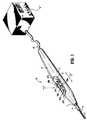
図1は、本開示の一実施形態に従って構築されかつ数字10により一般的に参照される、電気外科ペンシルの斜視図を示す。以下の説明は、電気外科ペンシルに関するが、本開示の特徴および概念(またはそれらの一部)は、任意の電気外科用器具(例えば、鉗子、吸引凝固器、脈管シーラーなど)に適用され得ることが、想定される。 FIG. 1 shows a perspective view of an electrosurgical pencil constructed in accordance with one embodiment of the present disclosure and generally referenced by
図1〜3において観察されるように、電気外科ペンシル10は、その遠位端3において刃レセプタクル4を支持するように構成され適合されている細長ハウジング2を備える。この刃レセプタクル4は、次に、ループ形態および/または刃形態の交換式電気焼灼エンドエフェクタ6をそのレセプタクル中に受容する。電気焼灼器刃6は、平面状刃、ループ、針などを備えることが理解される。刃6の遠位端部分8は、レセプタクル4から遠位方向に延び、一方、刃6の近位端部分11(図3参照)は、ハウジング2の遠位端3内に保持される。電気焼灼器刃6は、伝導型材料(例えば、ステンレス鋼)から製造されるか、または電導性材料で被覆されることが、企図される。 As observed in FIGS. 1-3, the
示されるように、電気外科ペンシル10は、ケーブル12を介して、従来の電気外科発電機「G」に接続される。ケーブル12は、伝送ワイヤ14(図3参照)を備える。この伝送ワイヤ14は、電気外科発電機「G」を、電気焼灼器刃6の近位端部分11と電気的に相互接続する。ケーブル12は、制御ワイヤ16をさらに備える。この制御ワイヤ16は、ハウジング2の外面7上に支持されるモード作動スイッチ群を(以下により詳細に記載されるように)電気外科発電機「G」と電気的に相互接続する。本明細書中の目的のために、用語「スイッチ」または「スイッチ群」は、電気的アクチュエーター、機械的アクチュエーター、電気機械的アクチュエーター(回転式アクチュエーター、旋回式アクチュエーター、トグル様アクチュエーター、ボタンなど)、または光学式アクチュエーターを包含する。 As shown,
図1〜3に戻ると、上記のように、電気外科ペンシル10は、少なくとも1つの作動スイッチ群(好ましくは、3つの作動スイッチ24a〜24c)をさらに備え、その各々は、ハウジング2の外面7上に支持される。各作動スイッチ24a〜24cは、触覚式構成要素26a〜26c上の特定の位置に、作動可能に接続される(例えば、スナップドーム(snap−dome)が示される)。次いで、これにより、発電機「G」から電気外科刃6へと供給される高周波(RF)電気エネルギーの伝達が制御される。より具体的には、触覚式構成要素26a〜26cは、電圧分割器ネットワーク27(本明細書中で以後、「VDN 27」)に、作動可能に接続され、このネットワークは、スイッチ閉鎖を形成する(例えば、ここでフィルム型電位差計として示される)。本明細書中の目的のために、用語「電圧分割器ネットワーク」は、直列に接続された電圧供給源にわたる出力電圧(例えば、2つのインピーダンスのうちの1つ)を決定する、抵抗スイッチの閉鎖、容量スイッチの閉鎖または誘導スイッチの閉鎖(など)の任意の公知の形態に関する。「電圧分割器」とは、本明細書中で使用される場合、直列に接続された複数の抵抗器に関し、それらの抵抗器は、適用される電圧の固定部分または変動部分を利用可能にするために、特定の点にタップを備える。 Returning to FIGS. 1-3, as described above, the
使用時には、どの作動スイッチ群24a〜24cが押されるかに依存して、個々のスイッチ26a〜26cは、押されてVDN 27と接触し、特徴的信号が、制御ワイヤ16を介して電気外科発電機「G」へと伝達される。制御ワイヤ16a〜16cは、好ましくは、VDN 27に作動可能に接続されている端子15(図2および図3を参照のこと)を介して、スイッチ群26a〜26cに電気外科的に接続される。例示のみとして、電気外科発電機「G」は、上記デバイスと組み合わせて使用され得、発電機「G」は、VDN設定を解釈してそれに応答するための回路を備える。 In use, depending on which
作動スイッチ群24a〜24cは、望ましい外科的意図を達成するために上記モードおよび/または「波形デューティサイクル」を制御するように構成され適合される。例えば、第一作動スイッチ24aは、電気外科発電機「G」へと特徴的信号を送達するように設定され得る。これによって、次に、切断効果/機能および/または解剖効果/機能を生じるデューティサイクルおよび/または波形形状が伝達される。一方、第二作動スイッチ24bは、電気外科発電機「G」へと特徴的信号を送達するように設定され得、これによって、次に、混合効果/機能(例えば、解剖効果/機能と止血効果/機能との組み合わせ)を生じるデューティサイクルおよび/または波形形状が伝達される。最後に、第三作動スイッチ24cは、電気発電機「G」に特徴的信号を送達するように設定され得、これによって、次に、止血効果/機能を生じるデューティサイクルおよび/または波形形状が伝達される。 The actuation switches 24a-24c are configured and adapted to control the above modes and / or “waveform duty cycle” to achieve the desired surgical intent. For example, the
第四の制御ワイヤ16d(すなわち、リターン制御ワイヤ)は、好ましくは、電気焼灼器刃6の近位端11に接続される。これにより、制御ワイヤ16a〜16cにおいて誘導される電気外科電流は、作動スイッチ群24a〜24cを通って電気焼灼器刃6へと流れるのを防がれる。次に、これによって、スイッチ群24a〜24cの寿命および使用期間が増加される。 The
このように、より複雑ではなくかつ/または比較的安価なスイッチ群24a〜24cが、選択され得る。なぜなら、そのスイッチは、作動の間に電流を伝達する必要がないからである。例えば、第四制御ワイヤ16dが提供される場合、スイッチ群24a〜24dは、プラスチックフィルム上に伝導性インクを印刷することによって、構築され得る。一方、第四制御ワイヤ16dが提供されない場合は、スイッチ群は、標準的な型打ちした金属から製造された型であり得、これにより、その器具の全体的複雑性およびコストが増加される。 In this way, less complex and / or relatively
図16を参照すると、本開示の一実施形態に従って、制御ワイヤ16a〜16dを作動用電気外科スイッチ群24a〜24cに相互接続し電気焼灼電力ワイヤ14を刃6に相互接続するための、電圧分割器ネットワーク(VDN)27が、示される。VDN 27は、制御ワイヤ16a〜16dのうちの1つ(例えば、制御ワイヤ16a)に電気的に接続された、電気外科ペンシル10の種々の様式を作動するための、第一伝達ライン27aを備える。VDN 27は、制御ワイヤ16a〜16dのうちの1つ(例えば、制御ワイヤ16b)に電気的に接続された、電気外科ペンシル10の種々の強度を作動するための、第二伝達ライン27bを備える。VDN 27は、VDN 27にかかる電圧を印加するための、第三伝達ライン27cおよび第四伝達ライン27dを備える。例えば、第三伝達ライン27cは、遮断されていても、接地されていてもよく、伝達ライン27dは、+5ボルトを伝達し得る。 Referring to FIG. 16, voltage division for interconnecting
例示のみとして、VDN 27は、伝達ライン27cと伝達ライン27dとの間に第一の直列に接続された複数の抵抗器群「R1」(例えば、6つの抵抗器)を備え得る。好ましくは、抵抗器群「R1」は、合わせて、合計約1000Ωの抵抗になる。この第一の直列の抵抗器群「R1」は、第一のスイッチ群の組「S1」によって実質的に各々が隔てられている。好ましくは、この第一のスイッチ群の組「S1」の各スイッチは、VDN 27の隣接する抵抗器群「R1」と、伝達ライン27aとの間で電気的に接続される。操作時には、第一のスイッチ群の組「S1」のうちのどのスイッチまたはスイッチ群が閉じられるかに依存して、電気外科ペンシル10についての種々の操作様式が、作動される。 By way of example only,
さらに、例示のみとして、VDN 27は、伝達ライン27cと伝達ライン27dとの間に第二の直列にて接続された、複数の抵抗器群「R2」(例えば、4つの抵抗器)を備え得る。好ましくは、抵抗器群「R2」は、合わさって、合計約1000Ωの抵抗になる。第二の直列の抵抗器群「R2」は、第二のスイッチ群の組「S2」によって各々隔てられている。好ましくは、その第二のスイッチ群の組「S2」の各スイッチは、VDN 27の隣接する抵抗器群「R2」と、伝達ライン27bとの間で電気的に接続される。操作時には、第二のスイッチ群の組「S2」のうちのどのスイッチまたはスイッチ群が閉じられるかに依存して、電気外科ペンシル10によって、種々の強度の高周波(RF)エネルギーが、伝達される。 Further, by way of example only,
図16においてもまた示されるように、伝達ワイヤ14は、VDN 27から遮断されているか、または完全に別個である。具体的には、伝達ワイヤ14は、RF入力または発電機「G」から、RF出力または電気焼灼器刃6まで直接延びる。 As also shown in FIG. 16, the
止血効果/機能は、約1%〜約12%のデューティサイクルを伴う波形を有するものとして規定され得る。融合効果/機能は、約12%〜約75%のデューティサイクルを伴う波形を有するものとして規定され得る。切断効果/機能および/または切開効果/機能は、約75%〜約100%のデューティサイクルを伴う波形を有するものとして規定され得る。これらのパーセンテージが、近似であって、種々の組織型および特徴に対して所望の外科手術効果を送達するためにカスタマイズされ得ることに注意することが重要である。 The hemostatic effect / function may be defined as having a waveform with a duty cycle of about 1% to about 12%. The fusion effect / function may be defined as having a waveform with a duty cycle of about 12% to about 75%. The cutting effect / function and / or the cutting effect / function may be defined as having a waveform with a duty cycle of about 75% to about 100%. It is important to note that these percentages are approximate and can be customized to deliver the desired surgical effect for various tissue types and features.
電気外科用ペンシル10は、ハウジング2上でスライド可能に支持される強度制御器28をさらに備える。強度制御器28は、一対のナブ29a、29bを備え、このナブ29a、29bは、各々一つが、それぞれのガイドチャネル30a、30b中にスライド可能に支持され、ガイドチャネル30a、30bは、ハウジング2の外部表面7上において作動スイッチ24a〜24cのいずれの側にも形成される。作動スイッチ24a〜24cのいずれの側にもナブ29a、29bを提供することによって、制御器28は、使用者のどちらの手によっても容易に操作され得るか、または同じ電気外科用ペンシルが、右利き使用者によっても左利き使用者によっても操作され得る。 The
好ましくは、強度制御器28は、スライド電位差計であり、このスライド電位差計において、ナブ29a、29bは、相対的に低い強度設定に対応する第一の位置(例えば、ケーブル12に最も近接した最大近位位置)、相対的に高い強度設定に対応する第二の位置(例えば、電気焼灼器末端効果器6に最も近接した最大遠位位置)、および中間的強度設定に対応する複数の中間位置を有する。理解され得るように、上記近位端から遠位端までの強度設定は、逆(例えば、高度から低度)にもなり得る。強度制御器28のナブ29a、29bおよび対応するガイドチャネル30a、30bが、一連の位置(好ましくは5箇所)を規定する、一連の協働する目立たない位置またはくぼんだ位置を提供されて、低い強度設定から高い強度設定まで、出力強度の容易な選択が可能になり得ることが企図される。一連の協働する目立たない位置またはくぼんだ位置はまた、外科医に、ある程度の触覚的なフィードバックを提供する。図2に最もよく見られるように、強度制御器28は、その上に提供された一連の印31を備え得、この印31は、ガイドチャネル30a、30bを通して見ることができる。印31は、好ましくは、一連の番号(例えば、番号1〜5)であり、この番号は、伝達されるべき強度のレベルを反映する。あるいは、レベルインジケーターが、ガイドチャネル30a、30bの側面に沿って印刷され得、これに沿って、ナブ29a、29bがスライドする。 Preferably, the
強度制御器28は、電力パラメータ(例えば、電圧強度、電力強度、および/もしくは電流強度)、ならびに/または電力 対 インピーダンス曲線形状を調節して、感知される出力強度に影響を与えるように構成され、かつ適合される。例えば、強度制御器28が、より遠位方向に配置される場合、より高いレベルの電力パラメータが電気焼灼器刃6に伝達される。おそらく、電流強度は、電気外科用刃を用い、かつ約2kΩの代表的組織インピーダンスを有する場合、約60mA〜約240mAの範囲に及び得る。60mAの強度レベルは、非常に軽度および/または最低限の、切断/切開/止血効果を提供する。240mAの強度レベルは、非常に攻撃的な切断/切開/止血効果を提供する。したがって、電流強度の好ましい範囲は、2kΩで約100mA〜約200mAである。
強度設定は、好ましくは、予め設定され、そして電気外科用装置/付属部品の選択、所望の外科手術効果、外科手術専門医および/または外科医の好みに基づいて、参照テーブルから選択される。この選択は、自動的になされ得るか、または使用者によって手動で選択され得る。強度値は、予め決定され得るか、または使用者によって調節され得る。 The intensity setting is preferably preset and selected from a lookup table based on electrosurgical device / accessory selection, desired surgical effect, surgical specialist and / or surgeon preference. This selection can be made automatically or can be manually selected by the user. The intensity value can be predetermined or adjusted by the user.
手術において、かつ所望される特定の電気外科用機能に依存して、外科医は、作動スイッチ24a〜24cの一つを、矢印「Y」(図1を参照のこと)により示された方向に押し下げ、これによって、VDN27に対する対応するスイッチ26a〜26cを駆動し、そしてこれによって、それぞれの特徴的な信号を、電気外科用発電機「G」に伝達する。例えば、外科医は、作動スイッチ24aを押し下げて切断機能および/または切開機能を実行し得るか、作動スイッチ24bを押し下げて融合機能を実行し得るか、または作動スイッチ24cを押し下げて止血機能を実行し得る。次いで、発電機「G」は、適切な波形出力を、伝達ワイヤ14を介して、電気焼灼器刃6に伝達する。 During surgery and depending on the particular electrosurgical function desired, the surgeon depresses one of the actuation switches 24a-24c in the direction indicated by the arrow “Y” (see FIG. 1). This drives the corresponding switch 26a-26c for the
電気外科用ペンシル10の電力パラメータの強度を変化させるために、外科医は、強度制御器28を、二方向の矢印「X」によって示される方向に移動する。上述のように、強度は、軽度な効果のためのおよそ60mAから、より攻撃的な効果のためのおよそ240mAまで、変化され得る。例えば、強度制御器28のナブ29a、29bをガイドチャネル30a、30bの最大近位端のより近くに(すなわち、ケーブル12のより近くに)配置することによって、より低い強度レベルが生成され、そして強度制御器28のナブ29a、29bをガイドチャネル30a、30bの最大遠位端のより近くに(すなわち、電気焼灼器末端効果器6のより近くに)配置することによって、より高い強度レベルが生成されて、より攻撃的な作用が生成される結果となる。強度制御器28のナブ29a、29bがガイドチャネル30a、30bの最大近位端に配置される場合、VDN27は、0位置および/または開位置に設定されることが想定される。好ましくは、電気外科用ペンシル10は、強度制御器28が0位置および/または開位置に設定された状態で、出荷される。 To change the power parameter intensity of the
好ましくは、強度制御器28は、3つの作動スイッチ24a〜24c全てによって同時に伝達される、電気外科用エネルギーの強度レベルを制御する。言い換えると、強度制御器28のナブ29a、29bがガイドチャネル30a、30bに対して配置される場合、3つの作動スイッチ24a〜24c全てに伝達される電気外科用エネルギーの強度レベルは、スライド電位差計または強度制御器28の同じ値へと設定される。 Preferably, the
安全上の注意として、電気外科用ペンシル10が一つのモードから別のモードへと変更される場合、強度制御器28は、それがリセットされなければならないように(すなわち、ナブ29a、29bが、ガイドチャネル30a、30bの最大近位端に再配置されて、VDN27を0位置および/または開位置に設定しなければならないように)構成され得ることが、想定される。リセットされた後、強度制御器28は、必要な場合、選択されたモードに対する所望の強度レベルおよび/または必要な強度レベルに調節され得る。 As a safety precaution, if the
VDN27がまた、各モードに対するすぐ前の強度レベル設定を格納するアルゴリズムを備え得ることが、想定され、かつ企図される。この様式において、強度制御器28は、特定のモードが再選択された場合、すぐ前の操作値へとリセットされる必要はない。 It is envisioned and contemplated that
電気外科用ペンシル10におけるVDN27および第4の制御ワイヤ16dの配置の組み合わせは、電気外科用ペンシル10内において、電気外科用システムの抵抗器ネットワーク全体(例えば、電気外科用ペンシル10および電気外科用エネルギーの供給源「G」)を実質的に配置する。従来の電気外科用システムは、代表的に、電気外科用ペンシルを作動するための、電気外科用ペンシル内に配置された電流制限用抵抗器、および伝達された電気外科用エネルギーの強度を制御するための、電気外科用エネルギーの供給源に配置された第二の抵抗器ネットワークを備える。本開示によると、第一および第二の抵抗器ネットワークの両方は、電気外科用ペンシル10内に配置される(すなわち、作動スイッチ24a〜24cによって示されるような、第一の抵抗器ネットワークは、および強度制御器28によって示されるような、第二の抵抗器ネットワーク)。 The combination of the arrangement of the
上記のように、強度制御器28は、ある程度の触覚的フィードバックを提供するように構成され得、かつ適合され得る。あるいは、可聴式のフィードバックが強度制御器28から生成され得る(例えば、「クリック音」)か、電気外科用エネルギー供給源「G」から生成され得る(例えば、「トーン音」)、および/または補助的音生成デバイス(例えば、ブザー)(示さず)から生成され得る。 As described above, the
好ましくは、図1および3に見られるように、強度制御器28および作動スイッチ24a〜24cは、ハウジング2の外壁7に形成された凹部9内に支持される。望ましくは、作動スイッチ24a〜24cは、電気外科用ペンシル10が外科医の手の中に保持される場合に外科医の指が通常静止する位置に配置され、一方強度制御器28のナブ29a、29bは、作動スイッチ24a〜24cと混同されない位置に配置される。あるいは、強度制御器28のナブ29a、29bは、電気外科用ペンシル10が外科医の手の中に保持される場合に外科医の指が通常静止する位置に配置され、一方作動スイッチ24a〜24cは、強度制御器28のナブ29a、29bと混同されない位置に配置される。加えて、ハウジング2の外壁7に形成された凹部9は、有利には、手術野にある間および/または外科手術手順の間、作動スイッチ24a〜24cおよび強度制御器28の不慮の起動(例えば、押し下げ、スライドおよび/または操作)を最小限にする。 Preferably, as seen in FIGS. 1 and 3, the
図3に見られるように、電気外科ペンシル10は、成形された/輪郭をつけたハンドグリップ5を備え、このハンドグリップ5は、ハウジング2の遠位端および近位端ならびにハウジング2の下面を、十分に取り巻く。輪郭をつけたハンドグリップ5は、外科医による電気外科ペンシル10の取扱いを改善するように成形され、寸法取りされる。従って、より低い圧力およびグリップ力が、電気外科的ペンシル10を使用および/または操作するのに必要とされ、それにより外科医が経験する疲労を強力に低減し、そして、ナブ29aおよび29bの近位および遠位の調整の間に電気外科ペンシル10の動きを防止するために、より低い圧力およびグリップ力が必要とされる。 As can be seen in FIG. 3, the
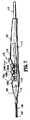
ここで、図4〜8を参照すると、本開示の別の実施形態に従って構成される電気外科ペンシルは、一般に100として示される。電気外科ペンシル100は、少なくとも1個の作動スイッチ、好ましくは3個の作動スイッチ124a〜124cを備え、それらのそれぞれは、ハウジング102の外表面107に支持される。各作動スイッチ124a〜124cは、それぞれのスイッチ126a〜126cに作動可能に接続され、次に、これらのスイッチ126a〜126cは、発電機「G」から電気焼灼器刃106に供給されるRF電気エネルギーの伝達を制御する。より詳細には、スイッチ126a〜126cは、コントロールループ116に電気的に接続され、そして、コントロールループ116を閉じ、そして/または、コントロールループ116を完成して、それによりRFエネルギーが電気外科的発電機「G」から電気焼灼器刃106に伝達されることを可能にするように、構成される。 4-8, an electrosurgical pencil configured in accordance with another embodiment of the present disclosure is indicated generally as 100. FIG. The
作動スイッチ124a〜124cは、上記電気外科ペンシル10の作動スイッチ24a〜24cと同じ様式で、所望の外科目的を達成するために、モードおよび/または「波形デューティサイクル」を制御するように構成され、適合される。
電気外科ペンシル100は、少なくとも1個の強度制御器、好ましくは2個の強度制御器128aおよび128bをさらに備え、これらの制御器のそれぞれは、ガイドチャネル130a、130b内にそれぞれスライドして支持され、これらのガイドチャネルは、ハウジング102の外表面107に形成される。好ましくは、各強度制御器128aおよび128bは、スライド様の電位差計である。各強度制御器128aおよび128bならびにガイドチャネル130aおよび130bは、最少量から最大量までの出力強度の容易な選択を可能にするために、一連の位置、好ましくは5個の位置を規定し、一連の共働する、不連続な位置かまたは移動止めされた位置を提供され得ることが意図される。一連の共働する不連続な位置または移動止めされた位置はまた、外科医にある程度の触覚フィードバックを提供する。強度制御器128a、128bに対する一連の位置の内の一つが、オフ位置(すなわち、伝達される電気エネルギーまたはRFエネルギーのレベルは0である)であることが、さらに想定される。 The
強度制御器128a、128bは、電力パラメータ(例えば、電圧、電力および/または電流の強さ)の内の一つおよび/または感知された出力強度に作用する電力対インピーダンス曲線の形状を調整するように構成され、適合される。
例えば、強度制御器128a、128bは、遠位の方向(すなわち、電気焼灼器刃106の向き)へとより大きく移動されるほど、電気焼灼器刃106に伝達される力パラメータのレベルはより大きくなる。おそらく、電気外科刃を使用し、約2000Ωの代表的な組織インピーダンスを有する場合、電流の強さは、約60mA〜約240mAの範囲であり得る。60mAの強度レベルは、非常に小さく、そして/または最小限の切断/解剖/止血効果を提供する。240mAの強度レベルは、非常に活動的な切断/解剖/止血効果を提供する。従って、好ましい電流の強度の範囲は、2kΩでは、約100mA〜約200mAである。 For example, the greater the
強度設定は好ましくは、電気外科器具/付属品、所望の外科的効果、所望の外科的特徴の選択および/または外科医の好みに基づいてルックアップテーブルから予め設定され、選択される。この選択は、自動的になされ得るか、または使用者によって手動で選択され得る。強度の値は、使用者によって予め決定され得るか、または調整され得る。 The intensity setting is preferably pre-set and selected from a look-up table based on the electrosurgical instrument / accessory, desired surgical effect, selection of desired surgical features and / or surgeon preference. This selection can be made automatically or can be manually selected by the user. The intensity value can be predetermined or adjusted by the user.
運転中、所望の特定の電気外科的機能に依存して、外科医は、作動スイッチ124a〜124cの内の一つを、矢印「Y」によって示される向き(図4および7を参照のこと)に押し下げ、それにより対応するスイッチ126a〜126cを閉じ、そしてコントロールループ116を閉じ、そして/または完成させる。例えば、外科医は、作動スイッチ124aを押し下げて切断機能または解剖機能を実施し得るか、作動スイッチ124bを押し下げて解剖/止血機能を実施し得るか、または作動スイッチ124cを押し下げて止血機能を実施し得る。次に、発電機「G」は、伝達ワイヤ114を介して適切な波形出力を電気焼灼器刃106に伝達する。 During operation, depending on the particular electrosurgical function desired, the surgeon places one of the
電気外科ペンシル100の電力パラメーター(好ましくは、電流の強さ)の強度を変動するために、外科医は、少なくとも一つの強度制御器128a、128bを、二方向の矢印「X」によって示される向きに移動させる。上記のように、強度は、小さい効果に対しての約60mAからより活動的な効果に対しての約240mAまで変動され得る。例えば、強度制御器128a、128bの内の一つを最も近位の端部に近接する(すなわち、ケーブル112に近接する)ように位置決めすることによって、小さい効果が生じ、そして、強度制御器128a、128bの内の一つを最も遠位の端部に近接する(すなわち、電気焼灼器刃106に近接する)ように位置決めすることによって、より活動的な効果が生じる。上記のように、各強度制御器128a、128bは、ある程度の触覚フィードバックを提供するように、構成され、適合され得る。あるいは、可聴性のフィードバックが、各強度制御器128a、128b(例えば、「クリック音」)、電気外科エネルギー源「G」(例えば、「音」)および/または補助的音発生デバイス(例えば、ブザー)(示さず)から生じ得る。 To vary the strength of the power parameter (preferably current strength) of the
代替的な実施形態において、図9および10に見られるように、スライディング強度制御器128a、128bは、ダイアル様のVDNの形態の強度制御器228a、228bで置き換えられている。強度制御器228a、228bは、二方向の矢印「Z」によって示されるように時計回りの向きか、または反時計回りの向きのどちらかでのダイアル制御器228a、228bの回転によって電力パラメータの強度を変動するように機能する。図6および7に見られるように、ダイアル制御器228a、228bは、ハウジング102の外部に配置されるが、外科医による操作のための部分のみがハウジング102から突出して、ダイアル制御器228a、228bがハウジング102内に配置されることが企図される。強度制御器228a、228bは、一対の対向したつまみ/ダイアル(ハウジング102の両側に1つずつ提供される)を有する単一の制御器であり得ることが想定される。この様式において、強度は、電気外科ペンシル100のどちらかの側からでも制御され得る。 In an alternative embodiment, as seen in FIGS. 9 and 10, the sliding
外科医は、その指の先端に多数の制御器を持っているので、純粋な「切断」効果から純粋な「凝固」効果までの範囲で変動する治療効果および多くの強度の間での多くの効果のパレットを作製し得る。さらに、電気外科エネルギー源「G」をある程度予め設定する場合、電気外科ペンシル100は、滅菌した領域内で外科医に利用可能である全ての有用な設定を有する。従って、一旦外科的手順が開始され、外科医が外科的手順に注意を集中することが可能であるようになると、外科医は、滅菌した領域の外側のハードウェア(例えば、電気外科エネルギー源「G」)と相互作用する必要はない。 The surgeon has multiple controls at the tip of his finger, so the therapeutic effect varies from a pure “cutting” effect to a pure “coagulation” effect and many effects between many intensities Pallets can be made. Furthermore, when the electrosurgical energy source “G” is pre-set to some extent, the
本開示に従った電気外科ペンシルの実施形態が、本明細書中に記載されるが、本開示が、それに限定されることは意図されず、上記記述は、好ましい実施形態の単なる例示と解釈されるべきである。当業者は、本開示の範囲内および本開示の精神内の他の改変を想定する。 While embodiments of electrosurgical pencils according to the present disclosure are described herein, the present disclosure is not intended to be limited thereto and the above description is to be construed as merely illustrative of the preferred embodiments. Should be. Those skilled in the art will envision other modifications within the scope and spirit of the present disclosure.
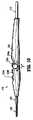
例えば、図11に見られるように、電気外科ペンシルの代替的な実施形態は、一般に200として示される。電気外科ペンシル200は、電気外科ペンシル10および/または100と類似していて、構造および操作における差異を同定するのに必要な程度まで詳細に議論されるのみである。図11に見られるように、電気外科ペンシル200は、複数のナブ、好ましくは3個のナブ、229a〜229cを備え、これらはそれぞれ、ハウジング2の外表面7に形成されたそれぞれのガイドチャネル230a〜230cにおいて1つずつ、作動スイッチ24a〜24cの近位にスライド可能に支持される。各ナブ229a〜229cは、スライド電位差計と作動可能に係合される。 For example, as seen in FIG. 11, an alternative embodiment of an electrosurgical pencil is indicated generally as 200. The
従って、電気外科ペンシル200は、各作動スイッチ24a〜24cが別々のモードであるように構成され得、例えば、作動スイッチ24aが、押し下げられた場合に、電気外科ペンシル200が「分割」を行なうように設定され得、作動スイッチ24bが、押し下げられた場合に、電気外科ペンシル200が「止血を伴う分割」を行うように設定され得、作動スイッチ24cが、押し下げられた場合に、電気外科ペンシル200が「止血」を行なうように設定され得る。さらに、各ナブ229a〜229cは、電気外科ペンシル200の操作の各モードに対する電力が独立に調節され得るように、対応する作動スイッチ24a〜24cと作動して係合する。 Accordingly, the
図12に見られるように、電気外科用ペンシルのナブ229a〜229cは、それぞれの作動スイッチ24a〜24cに作動可能に係合されたトグル231a〜231cで置き換えられている。各トグル231a〜231cは、上記のスライド型の電位差計の代わりに、ロッカー型スイッチ(図示せず)または回転式ダイアル(図示せず)と作動可能に係合され得る。 As seen in FIG. 12, the electrosurgical pencil nabs 229a-229c have been replaced with toggles 231a-231c operably engaged with
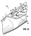
ここで図13〜15を参照して、本開示のなお別の実施形態に従う電気外科用ペンシルは、一般に300と示される。電気外科用ペンシル300は、電気外科用ペンシル10および/または100と類似しており、そして、組立ておよび操作における差異を識別するのに必要な程度まで詳細に議論されるのみである。図13および14に見られるように、ナブ29a、29bは、ハウジング2の外側表面7に形成された開口部330に回転可能に支持されたダイアル329で置き換えられている。好ましくは、ダイアル329は、作動スイッチ24a〜24cのいずれか1つの下降の間に、不注意に回転されないように、作動スイッチ24aの前方に位置付けられている。 13-15, an electrosurgical pencil according to yet another embodiment of the present disclosure is generally designated 300.
図13に見られるように、ダイアル329の側面331には、外科医に、電気外科用ペンシル300が設定された電力の程度および/またはレベルを示すために、目盛の形態および/または他の勾配の形態の指標および/または記号「M」が提供され得る。 As seen in FIG. 13, the
図14および15に見られるように、ウィンドウ332が、ハウジング2の外側表面7にあるダイアル329のいずれかの側面に形成され得る。図15に見られるように、ウィンドウ332は、外科医に、ダイアル329の中心軸から延びるスタブ333の上に提供された指標「M」の視感を提供する。指標「M」は、数、文字、色、そして図14および15に見られるように、拡大勾配の形態であり得る。各ダイアル329は、二重機能を実行し得、例えば、ダイアル329は、所望の電力レベルを設定するために回転され得、そして、所望のモードで電気外科用ペンシルを作動するように押し下げられ得ることが想定される。 As seen in FIGS. 14 and 15, a
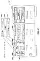
ここで図17を参照して、本開示の1つの実施形態に従う電気外科用発電機は、一般に「G」と示される。電気外科用発電機「G」は、複数のディスプレイ402(ここでは、3つのディスプレイ、402a〜402cが示される)を備える。ディスプレイ402a〜402cの各々は、数字404a〜404cによって示されるように、多数のスクリーン、ウィンドウまたはタブを備え得る。 Referring now to FIG. 17, an electrosurgical generator according to one embodiment of the present disclosure is generally designated “G”. The electrosurgical generator “G” includes a plurality of displays 402 (here, three displays, 402a-402c are shown). Each of the
各ディスプレイ402a〜402cの各スクリーン404a〜404cは、多数のディスプレイ要素406を備え得る。単なる一例として、図17に見られるように、ディスプレイ402aのスクリーン404bは、少なくとも3つのディスプレイ要素406a〜406cを備える。ディスプレイ要素406aは、電気外科用発電機「G」のモードおよび電力設定が、電気外科用ペンシル10に伝達されていることを示し得る。ディスプレイ要素406bは、電気外科用発電機「G」の範囲またはバーの設定が、電気外科用ペンシル10に伝達されていることを示し得る。ディスプレイ要素406cは、電気外科用ペンシル10上のスライダの位置を示し得る。 Each
ここで図18〜22を参照して、複数の設定(図19〜22)についての、図17の電気外科用発電機「G」を備える電気外科用ペンシル10の使用方法を示す流れ図(図18)が示され、説明される。まず、電気外科用発電機「G」のバーレベルまたは設定が、使用者によって選択される。単なる一例として、図17、19および20に見られるように、電気外科用発電機「G」は、5つのレベルまたは設定を備えるが、他の数のレベルまたは設定が可能である。図19および20の表に見られるように、特定のバーレベルまたは設定を選択することによって、電気外科用発電機「G」は、各作動モードについて、所定のレベルの電力および電流を供給するように設定される。 Referring now to FIGS. 18-22, a flow diagram illustrating the use of the
バーレベルまたは設定を選択すると、図18に見られるように、必要な場合または所望される場合、使用者は、ナブ29aおよび/または29bを電気外科用ペンシル10のガイドチャネル30a、30bに沿った多数の位置の1つまでスライドさせることによって、強度制御器28(図2)を設定する。強度制御器28のナブ29a、29bが示され、電気外科用ペンシル10に沿って5つの位置に設定可能であると説明されているが、この電気外科用ペンシル10は、強度制御器28のナブ29a、29bについて、5つより多くまたは5つより少ない設定可能な位置を提供するように構成され得ることが、考えられ、そしてこのことは本開示の範囲内である。強度制御器28を特定の設定に位置付けることによって、図19および20の表に見られるように、電気外科用発電機「G」は、各作動モードについて、所定のレベルの電力および電流を供給するように設定される。 Upon selection of the bar level or setting, as seen in FIG. 18, the user can move the
バーレベルまたは設定が選択され、そして、強度制御器28が設定されると、図18に見られるように、電気外科用ペンシル10の必須または所望の作動モードが、適切な、または対応する作動スイッチ24a〜24cを押すことによって作動される(図1)。上で説明したように、スイッチ24aが押されると、切断モードが作動し、スイッチ24bが押されると、融合または分割モードが作動し、そして、スイッチ24cが押されると、凝固モードが作動する。 When the bar level or setting is selected and the
例えば、図19に見られるように、電気外科用発電機「G」のバーレベルまたは設定が「2」に設定され、強度制御器28の位置が「4」に設定されると、各作動モードについての電力値は、次の通りである:切断について、モード1で150ワット;融合または分割について、モード2で100ワット;そして、凝固について、モード3で60ワット。さらに、図20に見られるように、この特定の設定について電流値は、次の通りである:切断について、モード1で0.625アンペア;融合または分割について、モード2で0.500アンペア;そして、凝固について、モード3で0.500アンペア。 For example, as seen in FIG. 19, when the bar level or setting of electrosurgical generator “G” is set to “2” and the position of
図21に見られるように、各作動モードについての出力周波数およびデューティサイクルが示される。図21にはまた、電気外科用発電機「G」のバーまたはレベル設定が「2」に設定される場合の、各作動モードについての、電気外科用ペンシル10の強度制御器28の各位置についての図20からの種々の電流設定のまとめが示される。 As seen in FIG. 21, the output frequency and duty cycle for each mode of operation is shown. FIG. 21 also shows each position of the
図22において、電気外科用発電機「G」のバーまたはレベル設定が「2」に設定される場合の、各作動モードについての、電気外科用ペンシル10の強度制御器28の各位置についての図19からの種々の電力設定のまとめが示される。 In FIG. 22, a diagram for each position of the
本明細書中に開示される任意の電気外科用ペンシルは、作動スイッチの1つが押される場合に、他の残りの作動スイッチが、押すことができないか、または電気焼灼器刃106に電気外科用エネルギーを伝達できないかのいずれかである、ロックアウト機構/システム(図示せず)を備え付けられ得ることがさらに想定される。 Any of the electrosurgical pencils disclosed herein can be electrosurgical to the
電気外科用ペンシル100は、発電機と連絡して、電気外科用ペンシルを識別し、電気外科用ペンシル100を用いて組織を処置することに関する種々の外科パラメータと連絡する、スマート認識技術を備え得ることがまた想定される。例えば、電気外科用ペンシル100は、発電機によって読み取り可能であり、かつ、発電機を電気外科用ペンシルを用いて組織を処置することに関連するデフォルトのパラメータにプリセットする、バーコードまたはAztecコードを備え付けられ得る。バーコードまたはAztecコードはまた、発電機により読み取り可能であり、使用前に、発電機を特定の電気パラメータにプログラムする、プログラム可能なデータを備え得る。 The
他のスマート認識技術がまた想定され、この技術は、発電機が利用される機器の型を決定すること、または、安全な機構として発電機に機器の適切な装着を保証することを可能にする。1つのこのような安全コネクタは、2003年11月20日に出願された、米国特許出願第10/718,114号に同定されており、この出願は、その全内容が本明細書中に参考として援用される。例えば、上記のスマート認識技術に加えて、このような安全コネクタは、電気外科用ペンシルに作動可能に接続されたプラグすなわち雄型部分、および、電気外科用発電機に作動可能に接続された補完型ソケットすなわち雌型部分を備え得る。ソケット部分は、「逆行適合性」であり、そこに開示される電気外科用ペンシルのコネクタ部分を受容し、そして、先行技術の電気外科用機器のコネクタ部分を受容する。 Other smart recognition technologies are also envisioned, which allows the generator to determine the type of equipment used, or to ensure proper installation of the equipment on the generator as a safe mechanism . One such safety connector is identified in US patent application Ser. No. 10 / 718,114, filed Nov. 20, 2003, which is hereby incorporated by reference in its entirety. Incorporated as. For example, in addition to the smart recognition technology described above, such a safety connector includes a plug or male portion operably connected to an electrosurgical pencil and a complement operably connected to an electrosurgical generator. A mold socket or female mold part may be provided. The socket portion is “retrocompatible” and receives the connector portion of the electrosurgical pencil disclosed therein and the connector portion of the prior art electrosurgical instrument.
電流制御は、電流密度に基づき得るか、または、確定した表面積について特定の電流(アンペア/cm2)を供給するように設計され得ることがまた想定される。It is also envisioned that current control can be based on current density or can be designed to provide a specific current (ampere / cm2 ) for a defined surface area.
本発明の装置が好ましい実施形態に関して記載されてきたが、本発明が属する技術の当業者には、変更および改変が、本発明の装置の精神および範囲から逸脱することなく、本発明の装置に対してなされ得ることが容易に理解される。 While the apparatus of the present invention has been described with respect to preferred embodiments, those skilled in the art to which the present invention pertains can be modified and modified without departing from the spirit and scope of the apparatus of the present invention. It will be readily understood that this can be done against.
2 細長ハウジング
6 電気焼灼器刃
10 電気外科用ペンシル
24a、24b、24c 作動スイッチ
27 電圧分割器ネットワーク2
Claims (35)
Translated fromJapanese細長ハウジング;
該ハウジング内に支持され、そして該ハウジングから遠位方向に延びる電気焼灼器電極であって、電気外科エネルギーの供給源に接続されている電気焼灼器電極;
該ハウジング上に支持された複数の作動スイッチであって、各作動スイッチがその作動の際に、該電気外科用エネルギーの供給源から延びる制御ループを選択的に完成する形態であり、かつ適合されている、複数の作動スイッチ;および
該ハウジング上に支持された少なくとも1つの電圧分割器ネットワークであって、該電気外科用ペンシルに送達される電気外科用エネルギーの強度を制御するために、該電気外科用エネルギー供給源に電気的に接続される、少なくとも1つの電圧分割器ネットワークを備える、電気外科用ペンシル。An electrosurgical pencil, with the following:
Elongated housing;
An electrocautery electrode supported within and extending distally from the housing and connected to a source of electrosurgical energy;
A plurality of actuation switches supported on the housing, each actuation switch being configured and adapted to selectively complete a control loop extending from the source of electrosurgical energy upon actuation. A plurality of actuation switches; and at least one voltage divider network supported on the housing to control the intensity of electrosurgical energy delivered to the electrosurgical pencil. An electrosurgical pencil comprising at least one voltage divider network electrically connected to a surgical energy source.
個々の作動スイッチを前記電気外科用エネルギーの供給源に電気的に相互接続する複数の制御ワイヤを備え、各制御ワイヤが、前記電気外科用ペンシル内で、前記電気焼灼器電極に電気外科エネルギーを送達する制御ワイヤから絶縁されている、請求項1に記載の電気外科用ペンシル。The at least one voltage divider network further includes:
A plurality of control wires electrically interconnecting individual actuation switches to the source of electrosurgical energy, each control wire providing electrosurgical energy to the electrocautery electrode within the electrosurgical pencil. The electrosurgical pencil according to claim1 , which is insulated from the delivery control wire.
Applications Claiming Priority (2)
| Application Number | Priority Date | Filing Date | Title |
|---|---|---|---|
| US10/959,824 | 2004-10-06 | ||
| US10/959,824US7156842B2 (en) | 2003-11-20 | 2004-10-06 | Electrosurgical pencil with improved controls |
Related Parent Applications (1)
| Application Number | Title | Priority Date | Filing Date |
|---|---|---|---|
| JP2005294215ADivisionJP4871566B2 (en) | 2004-10-06 | 2005-10-06 | Electrosurgical pencil with improved control |
Related Child Applications (1)
| Application Number | Title | Priority Date | Filing Date |
|---|---|---|---|
| JP2013136388ADivisionJP2013223769A (en) | 2004-10-06 | 2013-06-28 | Electrosurgical pencil with improved controls |
Publications (2)
| Publication Number | Publication Date |
|---|---|
| JP2012045409Atrue JP2012045409A (en) | 2012-03-08 |
| JP5437342B2 JP5437342B2 (en) | 2014-03-12 |
Family
ID=34592821
Family Applications (3)
| Application Number | Title | Priority Date | Filing Date |
|---|---|---|---|
| JP2005294215AExpired - Fee RelatedJP4871566B2 (en) | 2004-10-06 | 2005-10-06 | Electrosurgical pencil with improved control |
| JP2011235185AExpired - Fee RelatedJP5437342B2 (en) | 2004-10-06 | 2011-10-26 | Electrosurgical pencil with improved control |
| JP2013136388AWithdrawnJP2013223769A (en) | 2004-10-06 | 2013-06-28 | Electrosurgical pencil with improved controls |
Family Applications Before (1)
| Application Number | Title | Priority Date | Filing Date |
|---|---|---|---|
| JP2005294215AExpired - Fee RelatedJP4871566B2 (en) | 2004-10-06 | 2005-10-06 | Electrosurgical pencil with improved control |
Family Applications After (1)
| Application Number | Title | Priority Date | Filing Date |
|---|---|---|---|
| JP2013136388AWithdrawnJP2013223769A (en) | 2004-10-06 | 2013-06-28 | Electrosurgical pencil with improved controls |
Country Status (5)
| Country | Link |
|---|---|
| US (2) | US7156842B2 (en) |
| EP (2) | EP2292171A3 (en) |
| JP (3) | JP4871566B2 (en) |
| AU (1) | AU2005220218B2 (en) |
| CA (1) | CA2522240C (en) |
Families Citing this family (288)
| Publication number | Priority date | Publication date | Assignee | Title |
|---|---|---|---|---|
| US6267761B1 (en)* | 1997-09-09 | 2001-07-31 | Sherwood Services Ag | Apparatus and method for sealing and cutting tissue |
| US6726686B2 (en) | 1997-11-12 | 2004-04-27 | Sherwood Services Ag | Bipolar electrosurgical instrument for sealing vessels |
| US7435249B2 (en)* | 1997-11-12 | 2008-10-14 | Covidien Ag | Electrosurgical instruments which reduces collateral damage to adjacent tissue |
| US6228083B1 (en)* | 1997-11-14 | 2001-05-08 | Sherwood Services Ag | Laparoscopic bipolar electrosurgical instrument |
| US7267677B2 (en)* | 1998-10-23 | 2007-09-11 | Sherwood Services Ag | Vessel sealing instrument |
| US7118570B2 (en)* | 2001-04-06 | 2006-10-10 | Sherwood Services Ag | Vessel sealing forceps with disposable electrodes |
| US7582087B2 (en)* | 1998-10-23 | 2009-09-01 | Covidien Ag | Vessel sealing instrument |
| US20040249374A1 (en) | 1998-10-23 | 2004-12-09 | Tetzlaff Philip M. | Vessel sealing instrument |
| US7364577B2 (en) | 2002-02-11 | 2008-04-29 | Sherwood Services Ag | Vessel sealing system |
| US7137980B2 (en) | 1998-10-23 | 2006-11-21 | Sherwood Services Ag | Method and system for controlling output of RF medical generator |
| US6478793B1 (en)* | 1999-06-11 | 2002-11-12 | Sherwood Services Ag | Ablation treatment of bone metastases |
| US7887535B2 (en)* | 1999-10-18 | 2011-02-15 | Covidien Ag | Vessel sealing wave jaw |
| US20030109875A1 (en) | 1999-10-22 | 2003-06-12 | Tetzlaff Philip M. | Open vessel sealing forceps with disposable electrodes |
| US7101371B2 (en) | 2001-04-06 | 2006-09-05 | Dycus Sean T | Vessel sealer and divider |
| US10849681B2 (en) | 2001-04-06 | 2020-12-01 | Covidien Ag | Vessel sealer and divider |
| AU2002250551B2 (en)* | 2001-04-06 | 2006-02-02 | Covidien Ag | Molded insulating hinge for bipolar instruments |
| US20090292282A9 (en)* | 2001-04-06 | 2009-11-26 | Dycus Sean T | Movable handle for vessel sealer |
| EP1527747B1 (en)* | 2001-04-06 | 2015-09-30 | Covidien AG | Electrosurgical instrument which reduces collateral damage to adjacent tissue |
| AU2001249937B2 (en)* | 2001-04-06 | 2006-02-09 | Covidien Ag | Vessel sealing instrument |
| US20030229344A1 (en)* | 2002-01-22 | 2003-12-11 | Dycus Sean T. | Vessel sealer and divider and method of manufacturing same |
| ES2262639T3 (en) | 2001-04-06 | 2006-12-01 | Sherwood Services Ag | SHUTTER AND DIVIDER OF GLASSES WITH BUMPER MEMBERS N OCONDUCTIVES. |
| US20040115296A1 (en)* | 2002-04-05 | 2004-06-17 | Duffin Terry M. | Retractable overmolded insert retention apparatus |
| EP1683496B1 (en)* | 2002-06-06 | 2008-12-10 | Covidien AG | Laparoscopic bipolar electrosurgical instrument |
| JP2005533607A (en) | 2002-07-25 | 2005-11-10 | シャーウッド・サービシーズ・アクチェンゲゼルシャフト | Electrosurgical pencil with drag detection |
| US7270664B2 (en)* | 2002-10-04 | 2007-09-18 | Sherwood Services Ag | Vessel sealing instrument with electrical cutting mechanism |
| US7276068B2 (en) | 2002-10-04 | 2007-10-02 | Sherwood Services Ag | Vessel sealing instrument with electrical cutting mechanism |
| US7931649B2 (en) | 2002-10-04 | 2011-04-26 | Tyco Healthcare Group Lp | Vessel sealing instrument with electrical cutting mechanism |
| US7244257B2 (en) | 2002-11-05 | 2007-07-17 | Sherwood Services Ag | Electrosurgical pencil having a single button variable control |
| US7799026B2 (en)* | 2002-11-14 | 2010-09-21 | Covidien Ag | Compressible jaw configuration with bipolar RF output electrodes for soft tissue fusion |
| US7044948B2 (en) | 2002-12-10 | 2006-05-16 | Sherwood Services Ag | Circuit for controlling arc energy from an electrosurgical generator |
| US7033354B2 (en)* | 2002-12-10 | 2006-04-25 | Sherwood Services Ag | Electrosurgical electrode having a non-conductive porous ceramic coating |
| AU2004212990B2 (en) | 2003-02-20 | 2009-12-10 | Covidien Ag | Motion detector for controlling electrosurgical output |
| US20060052779A1 (en)* | 2003-03-13 | 2006-03-09 | Hammill Curt D | Electrode assembly for tissue fusion |
| US20060064086A1 (en)* | 2003-03-13 | 2006-03-23 | Darren Odom | Bipolar forceps with multiple electrode array end effector assembly |
| EP1601298B1 (en)* | 2003-03-13 | 2016-09-07 | Covidien AG | Bipolar concentric electrode assembly for soft tissue fusion |
| AU2004235739B2 (en)* | 2003-05-01 | 2010-06-17 | Covidien Ag | Method and system for programming and controlling an electrosurgical generator system |
| US7160299B2 (en) | 2003-05-01 | 2007-01-09 | Sherwood Services Ag | Method of fusing biomaterials with radiofrequency energy |
| US8128624B2 (en)* | 2003-05-01 | 2012-03-06 | Covidien Ag | Electrosurgical instrument that directs energy delivery and protects adjacent tissue |
| CA2523675C (en) | 2003-05-01 | 2016-04-26 | Sherwood Services Ag | Electrosurgical instrument which reduces thermal damage to adjacent tissue |
| JP5137230B2 (en) | 2003-05-15 | 2013-02-06 | コヴィディエン・アクチェンゲゼルシャフト | Tissue sealer with non-conductive variable stop member and method for sealing tissue |
| USD956973S1 (en) | 2003-06-13 | 2022-07-05 | Covidien Ag | Movable handle for endoscopic vessel sealer and divider |
| US7156846B2 (en) | 2003-06-13 | 2007-01-02 | Sherwood Services Ag | Vessel sealer and divider for use with small trocars and cannulas |
| US7857812B2 (en) | 2003-06-13 | 2010-12-28 | Covidien Ag | Vessel sealer and divider having elongated knife stroke and safety for cutting mechanism |
| US7150749B2 (en)* | 2003-06-13 | 2006-12-19 | Sherwood Services Ag | Vessel sealer and divider having elongated knife stroke and safety cutting mechanism |
| US7597693B2 (en)* | 2003-06-13 | 2009-10-06 | Covidien Ag | Vessel sealer and divider for use with small trocars and cannulas |
| WO2005050151A1 (en) | 2003-10-23 | 2005-06-02 | Sherwood Services Ag | Thermocouple measurement circuit |
| US7396336B2 (en) | 2003-10-30 | 2008-07-08 | Sherwood Services Ag | Switched resonant ultrasonic power amplifier system |
| US9848938B2 (en) | 2003-11-13 | 2017-12-26 | Covidien Ag | Compressible jaw configuration with bipolar RF output electrodes for soft tissue fusion |
| US7367976B2 (en)* | 2003-11-17 | 2008-05-06 | Sherwood Services Ag | Bipolar forceps having monopolar extension |
| US7232440B2 (en)* | 2003-11-17 | 2007-06-19 | Sherwood Services Ag | Bipolar forceps having monopolar extension |
| US7500975B2 (en)* | 2003-11-19 | 2009-03-10 | Covidien Ag | Spring loaded reciprocating tissue cutting mechanism in a forceps-style electrosurgical instrument |
| US7811283B2 (en)* | 2003-11-19 | 2010-10-12 | Covidien Ag | Open vessel sealing instrument with hourglass cutting mechanism and over-ratchet safety |
| US7131970B2 (en)* | 2003-11-19 | 2006-11-07 | Sherwood Services Ag | Open vessel sealing instrument with cutting mechanism |
| US7241294B2 (en) | 2003-11-19 | 2007-07-10 | Sherwood Services Ag | Pistol grip electrosurgical pencil with manual aspirator/irrigator and methods of using the same |
| US7879033B2 (en)* | 2003-11-20 | 2011-02-01 | Covidien Ag | Electrosurgical pencil with advanced ES controls |
| US7156844B2 (en) | 2003-11-20 | 2007-01-02 | Sherwood Services Ag | Electrosurgical pencil with improved controls |
| US7442193B2 (en) | 2003-11-20 | 2008-10-28 | Covidien Ag | Electrically conductive/insulative over-shoe for tissue fusion |
| US7156842B2 (en) | 2003-11-20 | 2007-01-02 | Sherwood Services Ag | Electrosurgical pencil with improved controls |
| US7503917B2 (en)* | 2003-11-20 | 2009-03-17 | Covidien Ag | Electrosurgical pencil with improved controls |
| US7780662B2 (en) | 2004-03-02 | 2010-08-24 | Covidien Ag | Vessel sealing system using capacitive RF dielectric heating |
| US20070016181A1 (en) | 2004-04-29 | 2007-01-18 | Van Der Weide Daniel W | Microwave tissue resection tool |
| US20070016180A1 (en)* | 2004-04-29 | 2007-01-18 | Lee Fred T Jr | Microwave surgical device |
| US20070055224A1 (en)* | 2004-04-29 | 2007-03-08 | Lee Fred T Jr | Intralumenal microwave device |
| US20060276781A1 (en)* | 2004-04-29 | 2006-12-07 | Van Der Weide Daniel W | Cannula cooling and positioning device |
| US7195631B2 (en)* | 2004-09-09 | 2007-03-27 | Sherwood Services Ag | Forceps with spring loaded end effector assembly |
| US7540872B2 (en) | 2004-09-21 | 2009-06-02 | Covidien Ag | Articulating bipolar electrosurgical instrument |
| US7955332B2 (en) | 2004-10-08 | 2011-06-07 | Covidien Ag | Mechanism for dividing tissue in a hemostat-style instrument |
| US7553309B2 (en) | 2004-10-08 | 2009-06-30 | Covidien Ag | Electrosurgical system employing multiple electrodes and method thereof |
| US20060079933A1 (en)* | 2004-10-08 | 2006-04-13 | Dylan Hushka | Latching mechanism for forceps |
| US20060190035A1 (en)* | 2004-10-08 | 2006-08-24 | Sherwood Services Ag | Latching mechanism for forceps |
| US7282049B2 (en)* | 2004-10-08 | 2007-10-16 | Sherwood Services Ag | Electrosurgical system employing multiple electrodes and method thereof |
| US7776035B2 (en)* | 2004-10-08 | 2010-08-17 | Covidien Ag | Cool-tip combined electrode introducer |
| US7686827B2 (en) | 2004-10-21 | 2010-03-30 | Covidien Ag | Magnetic closure mechanism for hemostat |
| US7686804B2 (en) | 2005-01-14 | 2010-03-30 | Covidien Ag | Vessel sealer and divider with rotating sealer and cutter |
| US7909823B2 (en) | 2005-01-14 | 2011-03-22 | Covidien Ag | Open vessel sealing instrument |
| US7491202B2 (en) | 2005-03-31 | 2009-02-17 | Covidien Ag | Electrosurgical forceps with slow closure sealing plates and method of sealing tissue |
| AU2006201358B2 (en)* | 2005-03-31 | 2011-10-27 | Covidien Ag | Electrosurgical pencil with advanced ES controls |
| US20060235378A1 (en)* | 2005-04-18 | 2006-10-19 | Sherwood Services Ag | Slider control for ablation handset |
| US7500974B2 (en)* | 2005-06-28 | 2009-03-10 | Covidien Ag | Electrode with rotatably deployable sheath |
| US7837685B2 (en)* | 2005-07-13 | 2010-11-23 | Covidien Ag | Switch mechanisms for safe activation of energy on an electrosurgical instrument |
| US7628791B2 (en)* | 2005-08-19 | 2009-12-08 | Covidien Ag | Single action tissue sealer |
| US7828794B2 (en) | 2005-08-25 | 2010-11-09 | Covidien Ag | Handheld electrosurgical apparatus for controlling operating room equipment |
| US20070066971A1 (en)* | 2005-09-21 | 2007-03-22 | Podhajsky Ronald J | Method and system for treating pain during an electrosurgical procedure |
| US7879031B2 (en)* | 2005-09-27 | 2011-02-01 | Covidien Ag | Cooled RF ablation needle |
| CA2561034C (en) | 2005-09-30 | 2014-12-09 | Sherwood Services Ag | Flexible endoscopic catheter with an end effector for coagulating and transfecting tissue |
| US7879035B2 (en)* | 2005-09-30 | 2011-02-01 | Covidien Ag | Insulating boot for electrosurgical forceps |
| AU2006225179B2 (en)* | 2005-09-30 | 2012-07-26 | Covidien Ag | In-line vessel sealer and divider |
| US7922953B2 (en) | 2005-09-30 | 2011-04-12 | Covidien Ag | Method for manufacturing an end effector assembly |
| ES2381560T3 (en) | 2005-09-30 | 2012-05-29 | Covidien Ag | Insulating sleeve for electrosurgical forceps |
| US7722607B2 (en)* | 2005-09-30 | 2010-05-25 | Covidien Ag | In-line vessel sealer and divider |
| US7789878B2 (en)* | 2005-09-30 | 2010-09-07 | Covidien Ag | In-line vessel sealer and divider |
| US20070078454A1 (en)* | 2005-09-30 | 2007-04-05 | Mcpherson James W | System and method for creating lesions using bipolar electrodes |
| US20070078453A1 (en)* | 2005-10-04 | 2007-04-05 | Johnson Kristin D | System and method for performing cardiac ablation |
| US20070118115A1 (en)* | 2005-11-22 | 2007-05-24 | Sherwood Services Ag | Bipolar electrosurgical sealing instrument having an improved tissue gripping device |
| US7594916B2 (en)* | 2005-11-22 | 2009-09-29 | Covidien Ag | Electrosurgical forceps with energy based tissue division |
| US7947039B2 (en)* | 2005-12-12 | 2011-05-24 | Covidien Ag | Laparoscopic apparatus for performing electrosurgical procedures |
| US8882766B2 (en)* | 2006-01-24 | 2014-11-11 | Covidien Ag | Method and system for controlling delivery of energy to divide tissue |
| US7766910B2 (en)* | 2006-01-24 | 2010-08-03 | Tyco Healthcare Group Lp | Vessel sealer and divider for large tissue structures |
| US8298232B2 (en) | 2006-01-24 | 2012-10-30 | Tyco Healthcare Group Lp | Endoscopic vessel sealer and divider for large tissue structures |
| CA2574934C (en) | 2006-01-24 | 2015-12-29 | Sherwood Services Ag | System and method for closed loop monitoring of monopolar electrosurgical apparatus |
| US8734443B2 (en) | 2006-01-24 | 2014-05-27 | Covidien Lp | Vessel sealer and divider for large tissue structures |
| US8241282B2 (en) | 2006-01-24 | 2012-08-14 | Tyco Healthcare Group Lp | Vessel sealing cutting assemblies |
| US20070173802A1 (en)* | 2006-01-24 | 2007-07-26 | Keppel David S | Method and system for transmitting data across patient isolation barrier |
| US7651493B2 (en)* | 2006-03-03 | 2010-01-26 | Covidien Ag | System and method for controlling electrosurgical snares |
| US10363092B2 (en) | 2006-03-24 | 2019-07-30 | Neuwave Medical, Inc. | Transmission line with heat transfer ability |
| US8672932B2 (en)* | 2006-03-24 | 2014-03-18 | Neuwave Medical, Inc. | Center fed dipole for use with tissue ablation systems, devices and methods |
| USD564321S1 (en) | 2006-04-12 | 2008-03-18 | Professional Tool Products, Llc | Portion of a housing for a rotary tool |
| US20070258838A1 (en)* | 2006-05-03 | 2007-11-08 | Sherwood Services Ag | Peristaltic cooling pump system |
| US7641653B2 (en)* | 2006-05-04 | 2010-01-05 | Covidien Ag | Open vessel sealing forceps disposable handswitch |
| US20070260240A1 (en)* | 2006-05-05 | 2007-11-08 | Sherwood Services Ag | Soft tissue RF transection and resection device |
| US20070260238A1 (en)* | 2006-05-05 | 2007-11-08 | Sherwood Services Ag | Combined energy level button |
| US7846158B2 (en) | 2006-05-05 | 2010-12-07 | Covidien Ag | Apparatus and method for electrode thermosurgery |
| US20070265616A1 (en)* | 2006-05-10 | 2007-11-15 | Sherwood Services Ag | Vessel sealing instrument with optimized power density |
| US20070282318A1 (en)* | 2006-05-16 | 2007-12-06 | Spooner Gregory J | Subcutaneous thermolipolysis using radiofrequency energy |
| US20080004619A1 (en)* | 2006-06-28 | 2008-01-03 | Synergetics Usa, Inc. | Electrosurgical bipolar instrument |
| US7776037B2 (en)* | 2006-07-07 | 2010-08-17 | Covidien Ag | System and method for controlling electrode gap during tissue sealing |
| US11389235B2 (en) | 2006-07-14 | 2022-07-19 | Neuwave Medical, Inc. | Energy delivery systems and uses thereof |
| US10376314B2 (en) | 2006-07-14 | 2019-08-13 | Neuwave Medical, Inc. | Energy delivery systems and uses thereof |
| US20080015575A1 (en)* | 2006-07-14 | 2008-01-17 | Sherwood Services Ag | Vessel sealing instrument with pre-heated electrodes |
| US7744615B2 (en)* | 2006-07-18 | 2010-06-29 | Covidien Ag | Apparatus and method for transecting tissue on a bipolar vessel sealing instrument |
| US7763018B2 (en)* | 2006-07-28 | 2010-07-27 | Covidien Ag | Cool-tip thermocouple including two-piece hub |
| US7731717B2 (en)* | 2006-08-08 | 2010-06-08 | Covidien Ag | System and method for controlling RF output during tissue sealing |
| US8597297B2 (en)* | 2006-08-29 | 2013-12-03 | Covidien Ag | Vessel sealing instrument with multiple electrode configurations |
| US7794457B2 (en)* | 2006-09-28 | 2010-09-14 | Covidien Ag | Transformer for RF voltage sensing |
| US8070746B2 (en) | 2006-10-03 | 2011-12-06 | Tyco Healthcare Group Lp | Radiofrequency fusion of cardiac tissue |
| US7951149B2 (en)* | 2006-10-17 | 2011-05-31 | Tyco Healthcare Group Lp | Ablative material for use with tissue treatment device |
| US7785060B2 (en)* | 2006-10-27 | 2010-08-31 | Applied Materials, Inc. | Multi-directional mechanical scanning in an ion implanter |
| US8211099B2 (en) | 2007-01-31 | 2012-07-03 | Tyco Healthcare Group Lp | Thermal feedback systems and methods of using the same |
| USD649249S1 (en) | 2007-02-15 | 2011-11-22 | Tyco Healthcare Group Lp | End effectors of an elongated dissecting and dividing instrument |
| US8267935B2 (en)* | 2007-04-04 | 2012-09-18 | Tyco Healthcare Group Lp | Electrosurgical instrument reducing current densities at an insulator conductor junction |
| US9486269B2 (en)* | 2007-06-22 | 2016-11-08 | Covidien Lp | Electrosurgical systems and cartridges for use therewith |
| US8777945B2 (en)* | 2007-06-29 | 2014-07-15 | Covidien Lp | Method and system for monitoring tissue during an electrosurgical procedure |
| US7834484B2 (en)* | 2007-07-16 | 2010-11-16 | Tyco Healthcare Group Lp | Connection cable and method for activating a voltage-controlled generator |
| US8506565B2 (en) | 2007-08-23 | 2013-08-13 | Covidien Lp | Electrosurgical device with LED adapter |
| US8181995B2 (en) | 2007-09-07 | 2012-05-22 | Tyco Healthcare Group Lp | Cool tip junction |
| US7877853B2 (en) | 2007-09-20 | 2011-02-01 | Tyco Healthcare Group Lp | Method of manufacturing end effector assembly for sealing tissue |
| US7877852B2 (en) | 2007-09-20 | 2011-02-01 | Tyco Healthcare Group Lp | Method of manufacturing an end effector assembly for sealing tissue |
| AU2008221509B2 (en) | 2007-09-28 | 2013-10-10 | Covidien Lp | Dual durometer insulating boot for electrosurgical forceps |
| US8235992B2 (en)* | 2007-09-28 | 2012-08-07 | Tyco Healthcare Group Lp | Insulating boot with mechanical reinforcement for electrosurgical forceps |
| US20090088745A1 (en)* | 2007-09-28 | 2009-04-02 | Tyco Healthcare Group Lp | Tapered Insulating Boot for Electrosurgical Forceps |
| US8267936B2 (en) | 2007-09-28 | 2012-09-18 | Tyco Healthcare Group Lp | Insulating mechanically-interfaced adhesive for electrosurgical forceps |
| US8235993B2 (en)* | 2007-09-28 | 2012-08-07 | Tyco Healthcare Group Lp | Insulating boot for electrosurgical forceps with exohinged structure |
| US8221416B2 (en)* | 2007-09-28 | 2012-07-17 | Tyco Healthcare Group Lp | Insulating boot for electrosurgical forceps with thermoplastic clevis |
| US8251996B2 (en)* | 2007-09-28 | 2012-08-28 | Tyco Healthcare Group Lp | Insulating sheath for electrosurgical forceps |
| US20090088750A1 (en)* | 2007-09-28 | 2009-04-02 | Tyco Healthcare Group Lp | Insulating Boot with Silicone Overmold for Electrosurgical Forceps |
| US9023043B2 (en)* | 2007-09-28 | 2015-05-05 | Covidien Lp | Insulating mechanically-interfaced boot and jaws for electrosurgical forceps |
| US8236025B2 (en)* | 2007-09-28 | 2012-08-07 | Tyco Healthcare Group Lp | Silicone insulated electrosurgical forceps |
| US20090088748A1 (en)* | 2007-09-28 | 2009-04-02 | Tyco Healthcare Group Lp | Insulating Mesh-like Boot for Electrosurgical Forceps |
| US8292880B2 (en) | 2007-11-27 | 2012-10-23 | Vivant Medical, Inc. | Targeted cooling of deployable microwave antenna |
| US8235987B2 (en) | 2007-12-05 | 2012-08-07 | Tyco Healthcare Group Lp | Thermal penetration and arc length controllable electrosurgical pencil |
| US8764748B2 (en)* | 2008-02-06 | 2014-07-01 | Covidien Lp | End effector assembly for electrosurgical device and method for making the same |
| US8623276B2 (en)* | 2008-02-15 | 2014-01-07 | Covidien Lp | Method and system for sterilizing an electrosurgical instrument |
| US8636733B2 (en) | 2008-03-31 | 2014-01-28 | Covidien Lp | Electrosurgical pencil including improved controls |
| US8597292B2 (en) | 2008-03-31 | 2013-12-03 | Covidien Lp | Electrosurgical pencil including improved controls |
| US8663218B2 (en) | 2008-03-31 | 2014-03-04 | Covidien Lp | Electrosurgical pencil including improved controls |
| US8162937B2 (en) | 2008-06-27 | 2012-04-24 | Tyco Healthcare Group Lp | High volume fluid seal for electrosurgical handpiece |
| US8469956B2 (en) | 2008-07-21 | 2013-06-25 | Covidien Lp | Variable resistor jaw |
| US8608739B2 (en)* | 2008-07-22 | 2013-12-17 | Covidien Lp | Electrosurgical devices, systems and methods of using the same |
| US8162973B2 (en)* | 2008-08-15 | 2012-04-24 | Tyco Healthcare Group Lp | Method of transferring pressure in an articulating surgical instrument |
| US8257387B2 (en)* | 2008-08-15 | 2012-09-04 | Tyco Healthcare Group Lp | Method of transferring pressure in an articulating surgical instrument |
| US9603652B2 (en)* | 2008-08-21 | 2017-03-28 | Covidien Lp | Electrosurgical instrument including a sensor |
| US8784417B2 (en)* | 2008-08-28 | 2014-07-22 | Covidien Lp | Tissue fusion jaw angle improvement |
| US8317787B2 (en)* | 2008-08-28 | 2012-11-27 | Covidien Lp | Tissue fusion jaw angle improvement |
| US20100057081A1 (en)* | 2008-08-28 | 2010-03-04 | Tyco Healthcare Group Lp | Tissue Fusion Jaw Angle Improvement |
| US8795274B2 (en)* | 2008-08-28 | 2014-08-05 | Covidien Lp | Tissue fusion jaw angle improvement |
| US20100063500A1 (en)* | 2008-09-05 | 2010-03-11 | Tyco Healthcare Group Lp | Apparatus, System and Method for Performing an Electrosurgical Procedure |
| US8303582B2 (en) | 2008-09-15 | 2012-11-06 | Tyco Healthcare Group Lp | Electrosurgical instrument having a coated electrode utilizing an atomic layer deposition technique |
| US20100069953A1 (en)* | 2008-09-16 | 2010-03-18 | Tyco Healthcare Group Lp | Method of Transferring Force Using Flexible Fluid-Filled Tubing in an Articulating Surgical Instrument |
| US20100076430A1 (en)* | 2008-09-24 | 2010-03-25 | Tyco Healthcare Group Lp | Electrosurgical Instrument Having a Thumb Lever and Related System and Method of Use |
| US9375254B2 (en)* | 2008-09-25 | 2016-06-28 | Covidien Lp | Seal and separate algorithm |
| US8535312B2 (en)* | 2008-09-25 | 2013-09-17 | Covidien Lp | Apparatus, system and method for performing an electrosurgical procedure |
| US8968314B2 (en)* | 2008-09-25 | 2015-03-03 | Covidien Lp | Apparatus, system and method for performing an electrosurgical procedure |
| US8142473B2 (en)* | 2008-10-03 | 2012-03-27 | Tyco Healthcare Group Lp | Method of transferring rotational motion in an articulating surgical instrument |
| US8469957B2 (en)* | 2008-10-07 | 2013-06-25 | Covidien Lp | Apparatus, system, and method for performing an electrosurgical procedure |
| US8016827B2 (en) | 2008-10-09 | 2011-09-13 | Tyco Healthcare Group Lp | Apparatus, system, and method for performing an electrosurgical procedure |
| US8636761B2 (en) | 2008-10-09 | 2014-01-28 | Covidien Lp | Apparatus, system, and method for performing an endoscopic electrosurgical procedure |
| US8486107B2 (en)* | 2008-10-20 | 2013-07-16 | Covidien Lp | Method of sealing tissue using radiofrequency energy |
| US8197479B2 (en)* | 2008-12-10 | 2012-06-12 | Tyco Healthcare Group Lp | Vessel sealer and divider |
| US8262652B2 (en) | 2009-01-12 | 2012-09-11 | Tyco Healthcare Group Lp | Imaginary impedance process monitoring and intelligent shut-off |
| US8114122B2 (en) | 2009-01-13 | 2012-02-14 | Tyco Healthcare Group Lp | Apparatus, system, and method for performing an electrosurgical procedure |
| US8231620B2 (en) | 2009-02-10 | 2012-07-31 | Tyco Healthcare Group Lp | Extension cutting blade |
| US20100256735A1 (en)* | 2009-04-03 | 2010-10-07 | Board Of Regents, The University Of Texas System | Intraluminal stent with seam |
| US9730749B2 (en) | 2009-04-17 | 2017-08-15 | Domain Surgical, Inc. | Surgical scalpel with inductively heated regions |
| US9265556B2 (en) | 2009-04-17 | 2016-02-23 | Domain Surgical, Inc. | Thermally adjustable surgical tool, balloon catheters and sculpting of biologic materials |
| US9078655B2 (en) | 2009-04-17 | 2015-07-14 | Domain Surgical, Inc. | Heated balloon catheter |
| US9131977B2 (en) | 2009-04-17 | 2015-09-15 | Domain Surgical, Inc. | Layered ferromagnetic coated conductor thermal surgical tool |
| US9107666B2 (en) | 2009-04-17 | 2015-08-18 | Domain Surgical, Inc. | Thermal resecting loop |
| US8211103B2 (en)* | 2009-04-24 | 2012-07-03 | Megadyne Medical Products, Inc. | Electrosurgical instrument with adjustable power cable |
| US8882767B2 (en) | 2009-04-24 | 2014-11-11 | Megadyne Medical Products, Inc. | Electrosurgical instrument with adjustable utility conduit |
| US8882768B2 (en) | 2009-04-24 | 2014-11-11 | Megadyne Medical Products, Inc. | Hand piece with adjustable utility conduit |
| US8187273B2 (en) | 2009-05-07 | 2012-05-29 | Tyco Healthcare Group Lp | Apparatus, system, and method for performing an electrosurgical procedure |
| US8246618B2 (en) | 2009-07-08 | 2012-08-21 | Tyco Healthcare Group Lp | Electrosurgical jaws with offset knife |
| EP3549544B1 (en) | 2009-07-28 | 2021-01-06 | Neuwave Medical, Inc. | DEVICE FOR ABLATION |
| US8133254B2 (en) | 2009-09-18 | 2012-03-13 | Tyco Healthcare Group Lp | In vivo attachable and detachable end effector assembly and laparoscopic surgical instrument and methods therefor |
| US8652125B2 (en)* | 2009-09-28 | 2014-02-18 | Covidien Lp | Electrosurgical generator user interface |
| US8112871B2 (en) | 2009-09-28 | 2012-02-14 | Tyco Healthcare Group Lp | Method for manufacturing electrosurgical seal plates |
| US9820806B2 (en)* | 2009-09-29 | 2017-11-21 | Covidien Lp | Switch assembly for electrosurgical instrument |
| US20110118733A1 (en)* | 2009-11-17 | 2011-05-19 | Kuo-Liang Liu | Electrosurgical pencil |
| JP5557522B2 (en)* | 2009-12-24 | 2014-07-23 | Ntn株式会社 | Remote control type actuator |
| ES2856026T3 (en) | 2010-05-03 | 2021-09-27 | Neuwave Medical Inc | Power supply systems |
| US9144455B2 (en) | 2010-06-07 | 2015-09-29 | Just Right Surgical, Llc | Low power tissue sealing device and method |
| US8998899B2 (en) | 2010-11-08 | 2015-04-07 | Bovie Medical Corporation | Multi-button electrosurgical apparatus |
| US9770285B2 (en) | 2010-11-08 | 2017-09-26 | Bovie Medical Corporation | System and method for identifying and controlling an electrosurgical apparatus |
| US9095333B2 (en) | 2012-07-02 | 2015-08-04 | Bovie Medical Corporation | Systems and methods of discriminating between argon and helium gases for enhanced safety of medical devices |
| US9060765B2 (en) | 2010-11-08 | 2015-06-23 | Bovie Medical Corporation | Electrosurgical apparatus with retractable blade |
| US9144453B2 (en) | 2010-11-08 | 2015-09-29 | Bovie Medical Corporation | Multi-mode electrosurgical apparatus |
| US9113940B2 (en) | 2011-01-14 | 2015-08-25 | Covidien Lp | Trigger lockout and kickback mechanism for surgical instruments |
| US8932279B2 (en) | 2011-04-08 | 2015-01-13 | Domain Surgical, Inc. | System and method for cooling of a heated surgical instrument and/or surgical site and treating tissue |
| EP2704657A4 (en) | 2011-04-08 | 2014-12-31 | Domain Surgical Inc | IMPEDANCE ADAPTATION CIRCUIT |
| WO2012158722A2 (en) | 2011-05-16 | 2012-11-22 | Mcnally, David, J. | Surgical instrument guide |
| US9358065B2 (en) | 2011-06-23 | 2016-06-07 | Covidien Lp | Shaped electrode bipolar resection apparatus, system and methods of use |
| CN102908187A (en)* | 2011-08-05 | 2013-02-06 | 余志能 | Throat minimally invasive surgery guided by self-retaining laryngoscope and monitored by fiber laryngoscope |
| WO2013040255A2 (en) | 2011-09-13 | 2013-03-21 | Domain Surgical, Inc. | Sealing and/or cutting instrument |
| US20130116682A1 (en) | 2011-11-09 | 2013-05-09 | Colorado State University Research Foundation | Non-Stick Conductive Coating for Biomedical Applications |
| GB2496624A (en)* | 2011-11-16 | 2013-05-22 | Gyrus Medical Ltd | Surgical instrument with a plurality of handswitches |
| JP2015506729A (en) | 2011-12-06 | 2015-03-05 | ドメイン・サージカル,インコーポレーテッド | System and method for controlling power supply to a surgical instrument |
| US9192438B2 (en) | 2011-12-21 | 2015-11-24 | Neuwave Medical, Inc. | Energy delivery systems and uses thereof |
| USD680220S1 (en) | 2012-01-12 | 2013-04-16 | Coviden IP | Slider handle for laparoscopic device |
| JP5657592B2 (en)* | 2012-03-12 | 2015-01-21 | 株式会社長田中央研究所 | Dental treatment equipment |
| US20130267787A1 (en)* | 2012-04-05 | 2013-10-10 | Innospan Enterprises, Inc. | Illuminated apparatus for electrocautery and devices and method of use |
| US9713493B2 (en) | 2012-04-30 | 2017-07-25 | Covidien Lp | Method of switching energy modality on a cordless RF device |
| US20140188107A1 (en) | 2012-12-31 | 2014-07-03 | Paul Joseph Weber | Methods and systems for tissue dissection and modification |
| US10045761B2 (en) | 2012-12-31 | 2018-08-14 | Tdm Surgitech, Inc. | Systems, apparatus and methods for tissue dissection |
| CN105380711B (en) | 2013-03-15 | 2018-01-02 | 捷锐士阿希迈公司(以奥林巴斯美国外科技术名义) | Combine electrosurgery device |
| WO2014143472A1 (en) | 2013-03-15 | 2014-09-18 | GYRUS ACMI, INC. (d/b/a OLYMPUS SURGICAL TECHNOLOGIES AMERICA) | Electrosurgical instrument |
| JP6153654B2 (en) | 2013-03-15 | 2017-06-28 | ジャイラス エーシーエムアイ インク | Combined electrosurgical device |
| US10492849B2 (en) | 2013-03-15 | 2019-12-03 | Cynosure, Llc | Surgical instruments and systems with multimodes of treatments and electrosurgical operation |
| JP6141506B2 (en)* | 2013-03-15 | 2017-06-07 | ジャイラス エーシーエムアイ インク | Combined electrosurgical device |
| CN105142556B (en) | 2013-03-15 | 2019-01-08 | 捷锐士阿希迈公司(以奥林巴斯美国外科技术名义) | Bias surgical clamp |
| USD765842S1 (en)* | 2013-06-05 | 2016-09-06 | Erbe Elektromedizin Gmbh | Hand grip |
| US9872719B2 (en) | 2013-07-24 | 2018-01-23 | Covidien Lp | Systems and methods for generating electrosurgical energy using a multistage power converter |
| US9655670B2 (en) | 2013-07-29 | 2017-05-23 | Covidien Lp | Systems and methods for measuring tissue impedance through an electrosurgical cable |
| CN105451670B (en) | 2013-08-07 | 2018-09-04 | 柯惠有限合伙公司 | Surgery forceps |
| EP3068316B1 (en) | 2013-11-13 | 2019-08-07 | Thixos LLC | Devices and kits for treatment of facet joints |
| US10237962B2 (en) | 2014-02-26 | 2019-03-19 | Covidien Lp | Variable frequency excitation plasma device for thermal and non-thermal tissue effects |
| USD750243S1 (en)* | 2014-04-11 | 2016-02-23 | Arthrocare Corporation | Electrosurgical wand handle with switches |
| US20150305798A1 (en)* | 2014-04-29 | 2015-10-29 | Jon Garito | Portable electrosurgical instrument |
| US10357306B2 (en) | 2014-05-14 | 2019-07-23 | Domain Surgical, Inc. | Planar ferromagnetic coated surgical tip and method for making |
| WO2016028835A1 (en) | 2014-08-20 | 2016-02-25 | GYRUS ACMI, INC. (d/b/a OLYMPUS SURGICAL TECHNOLOGIES AMERICA) | Surgical forceps and latching system |
| US10231777B2 (en) | 2014-08-26 | 2019-03-19 | Covidien Lp | Methods of manufacturing jaw members of an end-effector assembly for a surgical instrument |
| WO2016070009A1 (en)* | 2014-10-31 | 2016-05-06 | Medtronic Advanced Energy Llc | Power monitoring circuitry and method for reducing leakage current in rf generators |
| USD771257S1 (en)* | 2014-12-18 | 2016-11-08 | Karl Storz Gmbh & Co. Kg | Shaver handpiece |
| WO2016098664A1 (en) | 2014-12-19 | 2016-06-23 | オリンパス株式会社 | Substrate unit, operation input unit, energy treatment tool, and substrate unit production method |
| WO2016123147A1 (en) | 2015-01-28 | 2016-08-04 | Bovie Medical Corporation | Cold plasma electrosurgical apparatus with bent tip applicator |
| EP3581133A1 (en) | 2015-03-23 | 2019-12-18 | Gyrus ACMI, Inc. (D.B.A. Olympus Surgical Technologies America) | Medical forceps with vessel transection capability |
| US10327833B2 (en)* | 2015-03-24 | 2019-06-25 | Tdm Surgitech, Inc. | Electrosurgical switch assembly and related systems and methods |
| US9987078B2 (en) | 2015-07-22 | 2018-06-05 | Covidien Lp | Surgical forceps |
| US10342607B1 (en) | 2015-08-04 | 2019-07-09 | Brian K. Reaux | Electro-surgical pencil with an adjustable vacuum nozzle |
| US10987159B2 (en) | 2015-08-26 | 2021-04-27 | Covidien Lp | Electrosurgical end effector assemblies and electrosurgical forceps configured to reduce thermal spread |
| USD843572S1 (en)* | 2015-09-15 | 2019-03-19 | Jorge Albertal | Electrocautery blade |
| CN113367788B (en) | 2015-10-26 | 2024-09-06 | 纽韦弗医疗设备公司 | Energy delivery systems and uses thereof |
| US10368939B2 (en) | 2015-10-29 | 2019-08-06 | Covidien Lp | Non-stick coated electrosurgical instruments and method for manufacturing the same |
| US10441349B2 (en) | 2015-10-29 | 2019-10-15 | Covidien Lp | Non-stick coated electrosurgical instruments and method for manufacturing the same |
| US10213250B2 (en) | 2015-11-05 | 2019-02-26 | Covidien Lp | Deployment and safety mechanisms for surgical instruments |
| US11510730B2 (en) | 2016-03-26 | 2022-11-29 | Paul Joseph Weber | Apparatus and methods for minimally invasive dissection and modification of tissues |
| US10603101B2 (en) | 2016-03-26 | 2020-03-31 | Paul Joseph Weber | Apparatus, systems and methods for minimally invasive dissection of tissues |
| US10893899B2 (en) | 2016-03-26 | 2021-01-19 | Paul Weber | Apparatus and systems for minimally invasive dissection of tissues |
| US10531917B2 (en) | 2016-04-15 | 2020-01-14 | Neuwave Medical, Inc. | Systems and methods for energy delivery |
| US12376898B2 (en) | 2016-07-01 | 2025-08-05 | Cynosure, Llc | Non-invasive, uniform and non-uniform RF methods and systems related applications |
| US10856933B2 (en) | 2016-08-02 | 2020-12-08 | Covidien Lp | Surgical instrument housing incorporating a channel and methods of manufacturing the same |
| US10390903B2 (en) | 2016-10-24 | 2019-08-27 | Steven Warnock | Illuminated apparatus with telescoping for electrocautery devices and method of use |
| US10918407B2 (en) | 2016-11-08 | 2021-02-16 | Covidien Lp | Surgical instrument for grasping, treating, and/or dividing tissue |
| JP6342974B2 (en)* | 2016-11-24 | 2018-06-13 | ファナック株式会社 | Manual pulse generator |
| US20180147004A1 (en)* | 2016-11-29 | 2018-05-31 | Robert E. DeCou | Dual mode electrosurgical apparatus and method of manufacture |
| JP7112100B2 (en) | 2017-01-30 | 2022-08-03 | アピックス メディカル コーポレーション | Electrosurgical device with flexible shaft |
| US11166759B2 (en) | 2017-05-16 | 2021-11-09 | Covidien Lp | Surgical forceps |
| EP3629968B1 (en) | 2017-05-30 | 2024-11-20 | Apyx Medical Corporation | Electrosurgical apparatus with robotic tip |
| US11432869B2 (en) | 2017-09-22 | 2022-09-06 | Covidien Lp | Method for coating electrosurgical tissue sealing device with non-stick coating |
| US10709497B2 (en) | 2017-09-22 | 2020-07-14 | Covidien Lp | Electrosurgical tissue sealing device with non-stick coating |
| US11648047B2 (en) | 2017-10-06 | 2023-05-16 | Vive Scientific, Llc | System and method to treat obstructive sleep apnea |
| US10667834B2 (en) | 2017-11-02 | 2020-06-02 | Gyrus Acmi, Inc. | Bias device for biasing a gripping device with a shuttle on a central body |
| US11383373B2 (en) | 2017-11-02 | 2022-07-12 | Gyms Acmi, Inc. | Bias device for biasing a gripping device by biasing working arms apart |
| US11298801B2 (en) | 2017-11-02 | 2022-04-12 | Gyrus Acmi, Inc. | Bias device for biasing a gripping device including a central body and shuttles on the working arms |
| KR102726940B1 (en) | 2018-02-07 | 2024-11-05 | 싸이노슈어, 엘엘씨 | Methods and apparatus for controlled rf treatments and rf generator system |
| US11672596B2 (en) | 2018-02-26 | 2023-06-13 | Neuwave Medical, Inc. | Energy delivery devices with flexible and adjustable tips |
| EP3616637A1 (en)* | 2018-08-29 | 2020-03-04 | Erbe Elektromedizin GmbH | Medical instrument |
| USD904611S1 (en) | 2018-10-10 | 2020-12-08 | Bolder Surgical, Llc | Jaw design for a surgical instrument |
| US11832879B2 (en) | 2019-03-08 | 2023-12-05 | Neuwave Medical, Inc. | Systems and methods for energy delivery |
| US11207124B2 (en) | 2019-07-08 | 2021-12-28 | Covidien Lp | Electrosurgical system for use with non-stick coated electrodes |
| USD1005484S1 (en) | 2019-07-19 | 2023-11-21 | Cynosure, Llc | Handheld medical instrument and docking base |
| US11399888B2 (en) | 2019-08-14 | 2022-08-02 | Covidien Lp | Bipolar pencil |
| US11564732B2 (en) | 2019-12-05 | 2023-01-31 | Covidien Lp | Tensioning mechanism for bipolar pencil |
| US11369427B2 (en) | 2019-12-17 | 2022-06-28 | Covidien Lp | System and method of manufacturing non-stick coated electrodes |
| US11864818B2 (en) | 2020-06-12 | 2024-01-09 | Covidien Lp | End effector assembly for bipolar pencil |
| US12226143B2 (en) | 2020-06-22 | 2025-02-18 | Covidien Lp | Universal surgical footswitch toggling |
| USD934423S1 (en) | 2020-09-11 | 2021-10-26 | Bolder Surgical, Llc | End effector for a surgical device |
| USD1046129S1 (en) | 2021-04-14 | 2024-10-08 | Bolder Surgical, Llc | End effector for a surgical instrument |
| USD1092736S1 (en)* | 2023-12-13 | 2025-09-09 | Alesi Surgical Limited | Open surgery instrument |
Citations (2)
| Publication number | Priority date | Publication date | Assignee | Title |
|---|---|---|---|---|
| JPS61179142A (en)* | 1984-12-11 | 1986-08-11 | ヴアリ−ラブ・インコ−ポレ−テツド | Method and apparatus for processing demand performed from aseptic site of surgical treatment |
| WO2005060849A1 (en)* | 2003-11-20 | 2005-07-07 | Sherwood Services Ag | Electrosurgical pencil with plurality of controls |
Family Cites Families (413)
| Publication number | Priority date | Publication date | Assignee | Title |
|---|---|---|---|---|
| US2031682A (en) | 1932-11-18 | 1936-02-25 | Wappler Frederick Charles | Method and means for electrosurgical severance of adhesions |
| US2102270A (en) | 1935-11-29 | 1937-12-14 | Mortimer N Hyams | Electrosurgical device |
| NL101235C (en) | 1955-03-11 | |||
| BE556940A (en) | 1956-04-26 | |||
| US3219029A (en) | 1963-03-25 | 1965-11-23 | Groff De | Remote control medical therapy instrument |
| US3460539A (en) | 1967-03-10 | 1969-08-12 | James E Anhalt Sr | Cautery tip |
| US3494363A (en) | 1969-04-01 | 1970-02-10 | Technical Resources Inc | Control for devices used in surgery |
| US3648001A (en) | 1969-12-11 | 1972-03-07 | Robert K Anderson | Compact hand held switching device with insertable switching means |
| US3675655A (en) | 1970-02-04 | 1972-07-11 | Electro Medical Systems Inc | Method and apparatus for high frequency electric surgery |
| US4038984A (en) | 1970-02-04 | 1977-08-02 | Electro Medical Systems, Inc. | Method and apparatus for high frequency electric surgery |
| DE7023433U (en) | 1970-06-23 | 1974-07-11 | Siemens Ag | Handpiece for high frequency electrodes |
| US3699967A (en) | 1971-04-30 | 1972-10-24 | Valleylab Inc | Electrosurgical generator |
| US3825004A (en)* | 1972-09-13 | 1974-07-23 | Durden Enterprises Ltd | Disposable electrosurgical cautery |
| US3911241A (en) | 1972-12-15 | 1975-10-07 | Neomed Inc | Switching device for electro-surgical instruments |
| US3801800A (en) | 1972-12-26 | 1974-04-02 | Valleylab Inc | Isolating switching circuit for an electrosurgical generator |
| US3801766A (en) | 1973-01-22 | 1974-04-02 | Valleylab Inc | Switching means for an electro-surgical device including particular contact means and particular printed-circuit mounting means |
| US3974833A (en) | 1973-03-19 | 1976-08-17 | Durden Iii John G | Disposable electrosurgical cautery having optional suction control feature |
| US3828780A (en) | 1973-03-26 | 1974-08-13 | Valleylab Inc | Combined electrocoagulator-suction instrument |
| DE2324415C2 (en) | 1973-05-15 | 1975-06-05 | Aesculap-Werke Ag Vormals Jetter & Scheerer, 7200 Tuttlingen | Surgical suction device |
| FR2235669A1 (en) | 1973-07-07 | 1975-01-31 | Lunacek Boris | Gynaecological sterilisation instrument - has hollow electrode protruding from the end of a curved ended tube |
| US3875945A (en)* | 1973-11-02 | 1975-04-08 | Demetron Corp | Electrosurgery instrument |
| US3906955A (en) | 1974-05-06 | 1975-09-23 | Richard R Roberts | Surgical cauterizing tool having suction means |
| DE2429021C2 (en) | 1974-06-18 | 1983-12-08 | Erbe Elektromedizin GmbH, 7400 Tübingen | Remote switching device for an HF surgical device |
| DE2460481A1 (en) | 1974-12-20 | 1976-06-24 | Delma Elektro Med App | Electrode grip for remote HF surgical instrument switching - has shaped insulated piece with contact ring of sterilizable (silicon) rubber |
| US4014343A (en) | 1975-04-25 | 1977-03-29 | Neomed Incorporated | Detachable chuck for electro-surgical instrument |
| US3967084A (en)* | 1975-05-12 | 1976-06-29 | Kb-Denver, Inc. | Keyboard switch assemblies having two foot support legs on dome-shaped contact member |
| US4032738A (en)* | 1975-05-15 | 1977-06-28 | Neomed Incorporated | Electro-surgical instrument |
| US4034761A (en)* | 1975-12-15 | 1977-07-12 | The Birtcher Corporation | Disposable electrosurgical switching assembly |
| US4112950A (en) | 1976-10-22 | 1978-09-12 | Aspen Laboratories | Medical electronic apparatus and components |
| USD253247S (en) | 1978-03-20 | 1979-10-23 | Gill Earnest T | Electrical surgical probe |
| US4232676A (en) | 1978-11-16 | 1980-11-11 | Corning Glass Works | Surgical cutting instrument |
| US4314559A (en)* | 1979-12-12 | 1982-02-09 | Corning Glass Works | Nonstick conductive coating |
| US4620548A (en) | 1980-04-21 | 1986-11-04 | Accupap, Inc. | Pap smear T-zone sampler |
| US4921476A (en)* | 1980-10-08 | 1990-05-01 | Cavitron, Inc. | Method for preventing clogging of a surgical aspirator |
| DE3045996A1 (en)* | 1980-12-05 | 1982-07-08 | Medic Eschmann Handelsgesellschaft für medizinische Instrumente mbH, 2000 Hamburg | Electro-surgical scalpel instrument - has power supply remotely controlled by surgeon |
| US4562838A (en)* | 1981-01-23 | 1986-01-07 | Walker William S | Electrosurgery instrument |
| US4463759A (en) | 1982-01-13 | 1984-08-07 | Garito Jon C | Universal finger/foot switch adaptor for tube-type electrosurgical instrument |
| US4427006A (en)* | 1982-01-18 | 1984-01-24 | Medical Research Associates, Ltd. #1 | Electrosurgical instruments |
| US4443935A (en)* | 1982-03-01 | 1984-04-24 | Trident Surgical Corporation | Process for making electrosurgical scalpel pencil |
| US5370675A (en) | 1992-08-12 | 1994-12-06 | Vidamed, Inc. | Medical probe device and method |
| US4492231A (en)* | 1982-09-17 | 1985-01-08 | Auth David C | Non-sticking electrocautery system and forceps |
| US4492832A (en) | 1982-12-23 | 1985-01-08 | Neomed, Incorporated | Hand-controllable switching device for electrosurgical instruments |
| US4459443A (en)* | 1982-12-27 | 1984-07-10 | Cherry Electrical Products Corporation | Tactile feedback switch |
| US4545375A (en) | 1983-06-10 | 1985-10-08 | Aspen Laboratories, Inc. | Electrosurgical instrument |
| US4593691A (en) | 1983-07-13 | 1986-06-10 | Concept, Inc. | Electrosurgery electrode |
| US4463234A (en)* | 1983-11-02 | 1984-07-31 | Centralab Inc. | Tactile feel membrane switch assembly |
| US4619258A (en) | 1984-03-02 | 1986-10-28 | Dart Industries Inc. | Electrosurgical pencil providing blade isolation |
| US4595809A (en) | 1984-08-17 | 1986-06-17 | Dart Industries, Inc. | Snap action dome switch having wire contacts |
| US4657016A (en)* | 1984-08-20 | 1987-04-14 | Garito Jon C | Electrosurgical handpiece for blades, needles and forceps |
| US4754754A (en)* | 1984-08-20 | 1988-07-05 | Garito Jon C | Electrosurgical handpiece for blades and needles |
| KR900003546B1 (en) | 1984-09-29 | 1990-05-21 | 마쯔시다덴기산교 가부시기가이샤 | Push switch |
| US4827927A (en) | 1984-12-26 | 1989-05-09 | Valleylab, Inc. | Apparatus for changing the output power level of an electrosurgical generator while remaining in the sterile field of a surgical procedure |
| US4589411A (en)* | 1985-02-08 | 1986-05-20 | Aaron Friedman | Electrosurgical spark-gap cutting blade |
| US4606342A (en) | 1985-02-15 | 1986-08-19 | National Patent Development Corporation | Cautery device having a variable temperature cautery tip |
| US4625723A (en) | 1985-02-26 | 1986-12-02 | Medical Research Associates, Ltd. #1 | Pencil for electrosurgical generator |
| US4811733A (en) | 1985-03-14 | 1989-03-14 | Baxter Travenol Laboratories, Inc. | Electrosurgical device |
| US4655215A (en)* | 1985-03-15 | 1987-04-07 | Harold Pike | Hand control for electrosurgical electrodes |
| DE3523871C3 (en) | 1985-07-04 | 1994-07-28 | Erbe Elektromedizin | High frequency surgical device |
| US4640279A (en)* | 1985-08-08 | 1987-02-03 | Oximetrix, Inc. | Combination surgical scalpel and electrosurgical instrument |
| US4750488A (en) | 1986-05-19 | 1988-06-14 | Sonomed Technology, Inc. | Vibration apparatus preferably for endoscopic ultrasonic aspirator |
| US4642128A (en)* | 1985-09-11 | 1987-02-10 | Xanar, Inc. | Smoke evacuator system with electronic control circuitry |
| US4701193A (en) | 1985-09-11 | 1987-10-20 | Xanar, Inc. | Smoke evacuator system for use in laser surgery |
| US4872454A (en) | 1985-10-15 | 1989-10-10 | Lucas DeOliveira | Fluid control electrosurgical device |
| US5000754A (en) | 1985-10-15 | 1991-03-19 | Egidio L. DeOliveira | Fluid control electrosurgical method |
| DE8602882U1 (en) | 1986-02-05 | 1986-04-03 | Preh, Elektrofeinmechanische Werke Jakob Preh Nachf. Gmbh & Co, 8740 Bad Neustadt | Electric hand control device |
| US4712544A (en) | 1986-02-12 | 1987-12-15 | Castle Company | Electrosurgical generator |
| US4827911A (en)* | 1986-04-02 | 1989-05-09 | Cooper Lasersonics, Inc. | Method and apparatus for ultrasonic surgical fragmentation and removal of tissue |
| US4901719A (en)* | 1986-04-08 | 1990-02-20 | C. R. Bard, Inc. | Electrosurgical conductive gas stream equipment |
| US4846790A (en)* | 1986-04-09 | 1989-07-11 | Cooper Lasersonics, Inc. | Ultrasonic surgical system with irrigation manifold |
| US4988334A (en)* | 1986-04-09 | 1991-01-29 | Valleylab, Inc. | Ultrasonic surgical system with aspiration tubulation connector |
| US4683884A (en) | 1986-04-11 | 1987-08-04 | Md Engineering | Noise attenuating smokeless surgical device |
| US4688569A (en) | 1986-06-09 | 1987-08-25 | Medi-Tech, Inc. | Finger actuated surgical electrode holder |
| DE3689889D1 (en) | 1986-07-17 | 1994-07-07 | Erbe Elektromedizin | High-frequency surgical device for the thermal coagulation of biological tissues. |
| US4735603A (en)* | 1986-09-10 | 1988-04-05 | James H. Goodson | Laser smoke evacuation system and method |
| USD301739S (en) | 1986-10-15 | 1989-06-20 | Mdt Corporation | Electrosurgical pencil |
| US4876110A (en) | 1987-02-24 | 1989-10-24 | American Medical Products, Inc. | Electrosurgical knife |
| US4785807B1 (en) | 1987-02-24 | 1996-07-16 | American Medical Products Inc | Electrosurgical knife |
| SE459711B (en) | 1987-03-20 | 1989-07-31 | Swedemed Ab | EQUIPMENT FOR USE IN SURGICAL INTERVENTIONS TO DISPOSE TISSUE |
| DE3878477D1 (en) | 1987-04-10 | 1993-03-25 | Siemens Ag | MONITORING CIRCUIT FOR AN HF SURGERY DEVICE. |
| US4796623A (en) | 1987-07-20 | 1989-01-10 | The Cooper Companies, Inc. | Corneal vacuum trephine system |
| US5015227A (en)* | 1987-09-30 | 1991-05-14 | Valleylab Inc. | Apparatus for providing enhanced tissue fragmentation and/or hemostasis |
| US4931047A (en)* | 1987-09-30 | 1990-06-05 | Cavitron, Inc. | Method and apparatus for providing enhanced tissue fragmentation and/or hemostasis |
| US4909249A (en)* | 1987-11-05 | 1990-03-20 | The Cooper Companies, Inc. | Surgical cutting instrument |
| EP0653192B1 (en) | 1987-11-17 | 2000-04-12 | Erbe Elektromedizin GmbH | High frequence surgical device to cut and/or coagulate biological tissues |
| US5035695A (en) | 1987-11-30 | 1991-07-30 | Jaroy Weber, Jr. | Extendable electrocautery surgery apparatus and method |
| US4919129A (en) | 1987-11-30 | 1990-04-24 | Celebration Medical Products, Inc. | Extendable electrocautery surgery apparatus and method |
| US4862890A (en) | 1988-02-29 | 1989-09-05 | Everest Medical Corporation | Electrosurgical spatula blade with ceramic substrate |
| US4916275A (en)* | 1988-04-13 | 1990-04-10 | Square D Company | Tactile membrane switch assembly |
| US4869715A (en) | 1988-04-21 | 1989-09-26 | Sherburne Fred S | Ultrasonic cone and method of construction |
| DE3815835A1 (en) | 1988-05-09 | 1989-11-23 | Flachenecker Gerhard | HIGH FREQUENCY GENERATOR FOR TISSUE CUTTING AND COAGULATION IN HIGH FREQUENCY SURGERY |
| US4850353A (en)* | 1988-08-08 | 1989-07-25 | Everest Medical Corporation | Silicon nitride electrosurgical blade |
| US4949734A (en) | 1988-08-25 | 1990-08-21 | Gerald Bernstein | Shield for electrosurgical device |
| US4922903A (en) | 1988-10-06 | 1990-05-08 | Everest Medical Corporation | Handle for electro-surgical blade |
| US4903696A (en) | 1988-10-06 | 1990-02-27 | Everest Medical Corporation | Electrosurgical generator |
| US4986839A (en)* | 1988-11-10 | 1991-01-22 | Surgical Laser Products, Inc. | Self-contained air enhancement and laser plume evacuation system |
| US4911159A (en)* | 1988-11-21 | 1990-03-27 | Johnson Jeffrey W | Electrosurgical instrument with electrical contacts between the probe and the probe holder |
| US5026368A (en)* | 1988-12-28 | 1991-06-25 | Adair Edwin Lloyd | Method for cervical videoscopy |
| US5460602A (en) | 1989-01-23 | 1995-10-24 | Shapira; Nadiv | Smoke evacuator for smoke generating devices |
| US5192267A (en)* | 1989-01-23 | 1993-03-09 | Nadiv Shapira | Vortex smoke remover for electrosurgical devices |
| US5254082A (en) | 1989-02-18 | 1993-10-19 | Haruo Takase | Ultrasonic surgical scalpel |
| US5055100A (en) | 1989-06-19 | 1991-10-08 | Eugene Olsen | Suction attachment for electrosurgical instruments or the like |
| US5011483A (en) | 1989-06-26 | 1991-04-30 | Dennis Sleister | Combined electrosurgery and laser beam delivery device |
| US5076276A (en) | 1989-11-01 | 1991-12-31 | Olympus Optical Co., Ltd. | Ultrasound type treatment apparatus |
| US5797907A (en) | 1989-11-06 | 1998-08-25 | Mectra Labs, Inc. | Electrocautery cutter |
| US5085662A (en) | 1989-11-13 | 1992-02-04 | Scimed Life Systems, Inc. | Atherectomy catheter and related components |
| US5391144A (en) | 1990-02-02 | 1995-02-21 | Olympus Optical Co., Ltd. | Ultrasonic treatment apparatus |
| US5035696A (en) | 1990-02-02 | 1991-07-30 | Everest Medical Corporation | Electrosurgical instrument for conducting endoscopic retrograde sphincterotomy |
| US5046506A (en) | 1990-02-09 | 1991-09-10 | Singer Medical Products, Inc. | Molded needle with adhesive |
| US5244462A (en) | 1990-03-15 | 1993-09-14 | Valleylab Inc. | Electrosurgical apparatus |
| US5217457A (en)* | 1990-03-15 | 1993-06-08 | Valleylab Inc. | Enhanced electrosurgical apparatus |
| US5088997A (en)* | 1990-03-15 | 1992-02-18 | Valleylab, Inc. | Gas coagulation device |
| US5098430A (en)* | 1990-03-16 | 1992-03-24 | Beacon Laboratories, Inc. | Dual mode electrosurgical pencil |
| US5306238A (en)* | 1990-03-16 | 1994-04-26 | Beacon Laboratories, Inc. | Laparoscopic electrosurgical pencil |
| US5013312A (en) | 1990-03-19 | 1991-05-07 | Everest Medical Corporation | Bipolar scalpel for harvesting internal mammary artery |
| US5312400A (en) | 1992-10-09 | 1994-05-17 | Symbiosis Corporation | Cautery probes for endoscopic electrosurgical suction-irrigation instrument |
| US5431645A (en)* | 1990-05-10 | 1995-07-11 | Symbiosis Corporation | Remotely activated endoscopic tools such as endoscopic biopsy forceps |
| JPH0734805B2 (en) | 1990-05-16 | 1995-04-19 | アロカ株式会社 | Blood coagulator |
| US5071418A (en) | 1990-05-16 | 1991-12-10 | Joseph Rosenbaum | Electrocautery surgical scalpel |
| US5199944A (en)* | 1990-05-23 | 1993-04-06 | Ioan Cosmescu | Automatic smoke evacuator system for a surgical laser apparatus and method therefor |
| US5318516A (en)* | 1990-05-23 | 1994-06-07 | Ioan Cosmescu | Radio frequency sensor for automatic smoke evacuator system for a surgical laser and/or electrical apparatus and method therefor |
| US5233515A (en) | 1990-06-08 | 1993-08-03 | Cosman Eric R | Real-time graphic display of heat lesioning parameters in a clinical lesion generator system |
| US5154709A (en) | 1990-09-04 | 1992-10-13 | Johnson Gerald W | Vacuum hood attachment for electrosurgical instruments |
| US5246440A (en) | 1990-09-13 | 1993-09-21 | Noord Andrew J Van | Electrosurgical knife |
| US5409484A (en)* | 1990-09-24 | 1995-04-25 | Erlich; Frederick | Cautery with smoke removal apparatus |
| USD330253S (en) | 1990-10-04 | 1992-10-13 | Birtcher Medical Systems, Inc. | Electrosurgical handpiece |
| US5256138A (en) | 1990-10-04 | 1993-10-26 | The Birtcher Corporation | Electrosurgical handpiece incorporating blade and conductive gas functionality |
| US5100402A (en)* | 1990-10-05 | 1992-03-31 | Megadyne Medical Products, Inc. | Electrosurgical laparoscopic cauterization electrode |
| US5074863A (en) | 1990-10-12 | 1991-12-24 | Dines Lenna V | Disposable retractable surgical instrument |
| US5162044A (en) | 1990-12-10 | 1992-11-10 | Storz Instrument Company | Phacoemulsification transducer with rotatable handle |
| US5224944A (en)* | 1991-01-07 | 1993-07-06 | Elliott Martin P | Aspiration tip for a cautery handpiece |
| US5147292A (en) | 1991-02-05 | 1992-09-15 | C. R. Bard, Inc. | Control handle with locking means for surgical irrigation |
| US5226904A (en)* | 1991-02-08 | 1993-07-13 | Conmed Corporation | Electrosurgical instrument |
| US5300087A (en)* | 1991-03-22 | 1994-04-05 | Knoepfler Dennis J | Multiple purpose forceps |
| US5160334A (en) | 1991-04-30 | 1992-11-03 | Utah Medical Products, Inc. | Electrosurgical generator and suction apparatus |
| US5133714A (en)* | 1991-05-06 | 1992-07-28 | Kirwan Surgical Products, Inc. | Electrosurgical suction coagulator |
| US5195959A (en)* | 1991-05-31 | 1993-03-23 | Paul C. Smith | Electrosurgical device with suction and irrigation |
| US5178012A (en) | 1991-05-31 | 1993-01-12 | Rockwell International Corporation | Twisting actuator accelerometer |
| US5197962A (en)* | 1991-06-05 | 1993-03-30 | Megadyne Medical Products, Inc. | Composite electrosurgical medical instrument |
| US5190517A (en)* | 1991-06-06 | 1993-03-02 | Valleylab Inc. | Electrosurgical and ultrasonic surgical system |
| US5633578A (en) | 1991-06-07 | 1997-05-27 | Hemostatic Surgery Corporation | Electrosurgical generator adaptors |
| US5196007A (en)* | 1991-06-07 | 1993-03-23 | Alan Ellman | Electrosurgical handpiece with activator |
| US5472443A (en) | 1991-06-07 | 1995-12-05 | Hemostatic Surgery Corporation | Electrosurgical apparatus employing constant voltage and methods of use |
| US5234428A (en) | 1991-06-11 | 1993-08-10 | Kaufman David I | Disposable electrocautery/cutting instrument with integral continuous smoke evacuation |
| DE4122219A1 (en) | 1991-07-04 | 1993-01-07 | Delma Elektro Med App | ELECTRO-SURGICAL TREATMENT INSTRUMENT |
| US5312401A (en) | 1991-07-10 | 1994-05-17 | Electroscope, Inc. | Electrosurgical apparatus for laparoscopic and like procedures |
| US6022347A (en) | 1991-08-12 | 2000-02-08 | Karl Storz Gmbh & Co. | High-frequency surgical generator for adjusted cutting and coagulation |
| EP0598780B1 (en) | 1991-08-12 | 1999-03-03 | Karl Storz GmbH & Co. | Surgical high-frequency generator for cutting tissues |
| US5262241A (en)* | 1991-08-26 | 1993-11-16 | Eeonyx Corporation | Surface coated products |
| US5242442A (en) | 1991-09-18 | 1993-09-07 | Hirschfeld Jack J | Smoke aspirating electrosurgical device |
| US5178605A (en)* | 1991-09-23 | 1993-01-12 | Alcon Surgical, Inc. | Coaxial flow irrigating and aspirating ultrasonic handpiece |
| US5322503A (en) | 1991-10-18 | 1994-06-21 | Desai Ashvin H | Endoscopic surgical instrument |
| US5261906A (en) | 1991-12-09 | 1993-11-16 | Ralph Pennino | Electro-surgical dissecting and cauterizing instrument |
| US5254117A (en) | 1992-03-17 | 1993-10-19 | Alton Dean Medical | Multi-functional endoscopic probe apparatus |
| US5496314A (en) | 1992-05-01 | 1996-03-05 | Hemostatic Surgery Corporation | Irrigation and shroud arrangement for electrically powered endoscopic probes |
| JP3229020B2 (en)* | 1992-06-05 | 2001-11-12 | 大豊工業株式会社 | Slide bearing material |
| US5269781A (en) | 1992-06-10 | 1993-12-14 | Hewell Iii Todd S | Suction-assisted electrocautery unit |
| US5234429A (en) | 1992-07-06 | 1993-08-10 | Goldhaber Neil G | Cauterization instrument and associated surgical method |
| US5601224A (en)* | 1992-10-09 | 1997-02-11 | Ethicon, Inc. | Surgical instrument |
| US5788688A (en) | 1992-11-05 | 1998-08-04 | Bauer Laboratories, Inc. | Surgeon's command and control |
| US5318565A (en)* | 1992-11-12 | 1994-06-07 | Daniel B. Kuriloff | Suction cautery dissector |
| US5720745A (en)* | 1992-11-24 | 1998-02-24 | Erbe Electromedizin Gmbh | Electrosurgical unit and method for achieving coagulation of biological tissue |
| AU672227B2 (en)* | 1992-11-30 | 1996-09-26 | Sherwood Services Ag | An ultrasonic surgical handpiece and an energy initiator to maintain the vibration and linear dynamics |
| US5342356A (en) | 1992-12-02 | 1994-08-30 | Ellman Alan G | Electrical coupling unit for electrosurgery |
| US5468240A (en) | 1992-12-03 | 1995-11-21 | Conmed Corporation | Manual control device for laparoscopic instrument |
| US5431650A (en)* | 1992-12-11 | 1995-07-11 | Cosmescu; Ioan | Vortex hand piece shroud for automatic smoke evacuator system for a surgical laser apparatus and method therefor |
| US5693044A (en) | 1992-12-11 | 1997-12-02 | Cosmescu; Ioan | Telescopic surgical device and method therefor |
| US5697926A (en) | 1992-12-17 | 1997-12-16 | Megadyne Medical Products, Inc. | Cautery medical instrument |
| US5401273A (en)* | 1993-03-01 | 1995-03-28 | Shippert; Ronald D. | Cauterizing instrument for surgery |
| US5312329A (en)* | 1993-04-07 | 1994-05-17 | Valleylab Inc. | Piezo ultrasonic and electrosurgical handpiece |
| US5462522A (en) | 1993-04-19 | 1995-10-31 | Olympus Optical Co., Ltd. | Ultrasonic therapeutic apparatus |
| US5348555A (en) | 1993-04-26 | 1994-09-20 | Zinnanti William J | Endoscopic suction, irrigation and cautery instrument |
| US5406945A (en)* | 1993-05-24 | 1995-04-18 | Ndm Acquisition Corp. | Biomedical electrode having a secured one-piece conductive terminal |
| US5395363A (en)* | 1993-06-29 | 1995-03-07 | Utah Medical Products | Diathermy coagulation and ablation apparatus and method |
| FR2707154B1 (en) | 1993-07-08 | 1995-09-15 | Satelec Sa | Ultrasound scalpel. |
| US5366464A (en) | 1993-07-22 | 1994-11-22 | Belknap John C | Atherectomy catheter device |
| US5376089A (en) | 1993-08-02 | 1994-12-27 | Conmed Corporation | Electrosurgical instrument |
| US5380320A (en)* | 1993-11-08 | 1995-01-10 | Advanced Surgical Materials, Inc. | Electrosurgical instrument having a parylene coating |
| US5399823A (en)* | 1993-11-10 | 1995-03-21 | Minimed Inc. | Membrane dome switch with tactile feel regulator shim |
| US5484434A (en)* | 1993-12-06 | 1996-01-16 | New Dimensions In Medicine, Inc. | Electrosurgical scalpel |
| US5382247A (en)* | 1994-01-21 | 1995-01-17 | Valleylab Inc. | Technique for electrosurgical tips and method of manufacture and use |
| US5451222A (en) | 1994-03-16 | 1995-09-19 | Desentech, Inc. | Smoke evacuation system |
| US5484398A (en)* | 1994-03-17 | 1996-01-16 | Valleylab Inc. | Methods of making and using ultrasonic handpiece |
| US5472442A (en) | 1994-03-23 | 1995-12-05 | Valleylab Inc. | Moveable switchable electrosurgical handpiece |
| EP0688536B1 (en)* | 1994-03-23 | 2000-08-02 | Erbe Elektromedizin GmbH | Multifunctional instrument for ultrasonic surgery |
| US5413575A (en)* | 1994-04-19 | 1995-05-09 | Innovative Medical Technologies, Ltd. | Multifunction electrocautery tool |
| US5843021A (en) | 1994-05-09 | 1998-12-01 | Somnus Medical Technologies, Inc. | Cell necrosis apparatus |
| US5765418A (en)* | 1994-05-16 | 1998-06-16 | Medtronic, Inc. | Method for making an implantable medical device from a refractory metal |
| US5846236A (en) | 1994-07-18 | 1998-12-08 | Karl Storz Gmbh & Co. | High frequency-surgical generator for adjusted cutting and coagulation |
| AU694225B2 (en) | 1994-08-02 | 1998-07-16 | Ethicon Endo-Surgery, Inc. | Ultrasonic hemostatic and cutting instrument |
| US5561278A (en) | 1994-09-16 | 1996-10-01 | Rutten; Phillip | Membrane switch |
| US6646541B1 (en) | 1996-06-24 | 2003-11-11 | Computer Motion, Inc. | General purpose distributed operating room control system |
| US7053752B2 (en)* | 1996-08-06 | 2006-05-30 | Intuitive Surgical | General purpose distributed operating room control system |
| US5674219A (en) | 1994-10-06 | 1997-10-07 | Donaldson Company, Inc. | Electrosurgical smoke evacuator |
| US5531722A (en)* | 1994-11-21 | 1996-07-02 | Van Hale; Gregory L. | Aspiration unit |
| US5549604A (en) | 1994-12-06 | 1996-08-27 | Conmed Corporation | Non-Stick electroconductive amorphous silica coating |
| US5713895A (en)* | 1994-12-30 | 1998-02-03 | Valleylab Inc | Partially coated electrodes |
| US5486162A (en)* | 1995-01-11 | 1996-01-23 | Fibrasonics, Inc. | Bubble control device for an ultrasonic surgical probe |
| US5669907A (en) | 1995-02-10 | 1997-09-23 | Valleylab Inc. | Plasma enhanced bipolar electrosurgical system |
| US5630426A (en) | 1995-03-03 | 1997-05-20 | Neovision Corporation | Apparatus and method for characterization and treatment of tumors |
| US6213999B1 (en)* | 1995-03-07 | 2001-04-10 | Sherwood Services Ag | Surgical gas plasma ignition apparatus and method |
| USD370731S (en) | 1995-03-07 | 1996-06-11 | Medtronic, Inc. | Electrocautery handle |
| US5626575A (en) | 1995-04-28 | 1997-05-06 | Conmed Corporation | Power level control apparatus for electrosurgical generators |
| US6425912B1 (en) | 1995-05-05 | 2002-07-30 | Thermage, Inc. | Method and apparatus for modifying skin surface and soft tissue structure |
| US6241753B1 (en) | 1995-05-05 | 2001-06-05 | Thermage, Inc. | Method for scar collagen formation and contraction |
| US5755753A (en) | 1995-05-05 | 1998-05-26 | Thermage, Inc. | Method for controlled contraction of collagen tissue |
| US5643256A (en)* | 1995-05-19 | 1997-07-01 | Urueta; R. Wilfrido | Gold-plated electrosurgical instrument |
| AU5841096A (en) | 1995-05-31 | 1996-12-18 | Nuvotek Ltd | Electrosurgical cutting and coagulation apparatus |
| WO1996039086A1 (en) | 1995-06-06 | 1996-12-12 | Valleylab Inc. | Power control for an electrosurgical generator |
| US6632193B1 (en) | 1995-06-07 | 2003-10-14 | Arthrocare Corporation | Systems and methods for electrosurgical tissue treatment |
| US5658302A (en)* | 1995-06-07 | 1997-08-19 | Baxter International Inc. | Method and device for endoluminal disruption of venous valves |
| US5634935A (en) | 1995-06-16 | 1997-06-03 | Taheri; Syde A. | Balloon dissection instrument and method of dissection |
| US6293942B1 (en) | 1995-06-23 | 2001-09-25 | Gyrus Medical Limited | Electrosurgical generator method |
| GB9526627D0 (en) | 1995-12-29 | 1996-02-28 | Gyrus Medical Ltd | An electrosurgical instrument and an electrosurgical electrode assembly |
| US6458125B1 (en) | 1995-07-10 | 2002-10-01 | I. C. Medical, Inc. | Electro-surgical unit pencil apparatus and method therefor |
| US5693052A (en) | 1995-09-01 | 1997-12-02 | Megadyne Medical Products, Inc. | Coated bipolar electrocautery |
| US5630417A (en) | 1995-09-08 | 1997-05-20 | Acuson Corporation | Method and apparatus for automated control of an ultrasound transducer |
| US5702387A (en) | 1995-09-27 | 1997-12-30 | Valleylab Inc | Coated electrosurgical electrode |
| US5712543A (en) | 1995-10-31 | 1998-01-27 | Smith & Nephew Endoscopy Inc. | Magnetic switching element for controlling a surgical device |
| US5693050A (en) | 1995-11-07 | 1997-12-02 | Aaron Medical Industries, Inc. | Electrosurgical instrument |
| US5630812A (en) | 1995-12-11 | 1997-05-20 | Ellman; Alan G. | Electrosurgical handpiece with locking nose piece |
| US7141049B2 (en) | 1999-03-09 | 2006-11-28 | Thermage, Inc. | Handpiece for treatment of tissue |
| US6350276B1 (en) | 1996-01-05 | 2002-02-26 | Thermage, Inc. | Tissue remodeling apparatus containing cooling fluid |
| US7473251B2 (en) | 1996-01-05 | 2009-01-06 | Thermage, Inc. | Methods for creating tissue effect utilizing electromagnetic energy and a reverse thermal gradient |
| US7006874B2 (en) | 1996-01-05 | 2006-02-28 | Thermage, Inc. | Treatment apparatus with electromagnetic energy delivery device and non-volatile memory |
| US7452358B2 (en) | 1996-01-05 | 2008-11-18 | Thermage, Inc. | RF electrode assembly for handpiece |
| US20040000316A1 (en) | 1996-01-05 | 2004-01-01 | Knowlton Edward W. | Methods for creating tissue effect utilizing electromagnetic energy and a reverse thermal gradient |
| US20030212393A1 (en) | 1996-01-05 | 2003-11-13 | Knowlton Edward W. | Handpiece with RF electrode and non-volatile memory |
| US7115123B2 (en) | 1996-01-05 | 2006-10-03 | Thermage, Inc. | Handpiece with electrode and non-volatile memory |
| US7189230B2 (en) | 1996-01-05 | 2007-03-13 | Thermage, Inc. | Method for treating skin and underlying tissue |
| US7229436B2 (en) | 1996-01-05 | 2007-06-12 | Thermage, Inc. | Method and kit for treatment of tissue |
| US6413255B1 (en) | 1999-03-09 | 2002-07-02 | Thermage, Inc. | Apparatus and method for treatment of tissue |
| US7267675B2 (en) | 1996-01-05 | 2007-09-11 | Thermage, Inc. | RF device with thermo-electric cooler |
| US7022121B2 (en) | 1999-03-09 | 2006-04-04 | Thermage, Inc. | Handpiece for treatment of tissue |
| US5634912A (en)* | 1996-02-12 | 1997-06-03 | Alcon Laboratories, Inc. | Infusion sleeve |
| US6117134A (en) | 1996-02-14 | 2000-09-12 | Cunningham; James Steven | Instrument for suction electrosurgery |
| US5609573A (en)* | 1996-02-28 | 1997-03-11 | Conmed Corporation | Electrosurgical suction/irrigation instrument |
| CA2221414C (en)* | 1996-03-18 | 2006-05-02 | 688726 Alberta Ltd. | Electrotherapy device |
| USD384148S (en) | 1996-03-18 | 1997-09-23 | Donaldson Company, Inc. | Smoke evacuator for an electrocautery scalpel |
| DE19706269A1 (en) | 1996-03-21 | 1997-09-25 | Valleylab Inc | Instrument for gas-enriched electrosurgery |
| US6361532B1 (en)* | 1996-05-01 | 2002-03-26 | Bovie Medical Corporation | Electrosurgical pencil |
| US5843109A (en) | 1996-05-29 | 1998-12-01 | Allergan | Ultrasonic handpiece with multiple piezoelectric elements and heat dissipator |
| AUPO044596A0 (en) | 1996-06-14 | 1996-07-11 | Skop Gmbh Ltd | Improved electrical signal supply |
| US5888200A (en) | 1996-08-02 | 1999-03-30 | Stryker Corporation | Multi-purpose surgical tool system |
| US6017354A (en) | 1996-08-15 | 2000-01-25 | Stryker Corporation | Integrated system for powered surgical tools |
| USD393067S (en)* | 1996-08-27 | 1998-03-31 | Valleylab Inc. | Electrosurgical pencil |
| US5755716A (en) | 1996-08-30 | 1998-05-26 | Garito; Jon C. | Method for using an electrosurgical electrode for treating glaucoma |
| US5941887A (en) | 1996-09-03 | 1999-08-24 | Bausch & Lomb Surgical, Inc. | Sleeve for a surgical instrument |
| US5836909A (en) | 1996-09-13 | 1998-11-17 | Cosmescu; Ioan | Automatic fluid control system for use in open and laparoscopic laser surgery and electrosurgery and method therefor |
| US6355034B2 (en) | 1996-09-20 | 2002-03-12 | Ioan Cosmescu | Multifunctional telescopic monopolar/bipolar surgical device and method therefor |
| US7112199B2 (en) | 1996-09-20 | 2006-09-26 | Ioan Cosmescu | Multifunctional telescopic monopolar/bipolar surgical device and method therefore |
| US6036667A (en)* | 1996-10-04 | 2000-03-14 | United States Surgical Corporation | Ultrasonic dissection and coagulation system |
| US6099525A (en) | 1996-10-07 | 2000-08-08 | Cosmescu; Ioan | Removable shroud for receiving a pencil used in electro-surgery |
| US5800431A (en) | 1996-10-11 | 1998-09-01 | Brown; Robert H. | Electrosurgical tool with suction and cautery |
| US5893848A (en) | 1996-10-24 | 1999-04-13 | Plc Medical Systems, Inc. | Gauging system for monitoring channel depth in percutaneous endocardial revascularization |
| US7204832B2 (en)* | 1996-12-02 | 2007-04-17 | Pálomar Medical Technologies, Inc. | Cooling system for a photo cosmetic device |
| US5899915A (en) | 1996-12-02 | 1999-05-04 | Angiotrax, Inc. | Apparatus and method for intraoperatively performing surgery |
| US5876400A (en) | 1997-01-13 | 1999-03-02 | Pioneer Laboratories, Inc. | Electrocautery method and apparatus |
| US5951548A (en) | 1997-02-21 | 1999-09-14 | Stephen R. DeSisto | Self-evacuating electrocautery device |
| US5944737A (en) | 1997-10-10 | 1999-08-31 | Ethicon Endo-Surgery, Inc. | Ultrasonic clamp coagulator apparatus having improved waveguide support member |
| US20020026145A1 (en) | 1997-03-06 | 2002-02-28 | Bagaoisan Celso J. | Method and apparatus for emboli containment |
| US5893862A (en)* | 1997-04-10 | 1999-04-13 | Pratt; Arthur William | Surgical apparatus |
| ES2353846T3 (en) | 1997-04-11 | 2011-03-07 | United States Surgical Corporation | APPLIANCE FOR RF ABLATION AND CONTROLLER OF THE SAME. |
| GB9708268D0 (en) | 1997-04-24 | 1997-06-18 | Gyrus Medical Ltd | An electrosurgical instrument |
| US5913864A (en) | 1997-06-09 | 1999-06-22 | Garito; Jon C. | Electrosurgical dermatological curet |
| US5938589A (en) | 1997-07-15 | 1999-08-17 | Fuji Photo Optical Co., Ltd. | Control switch device for an endoscope duct |
| US6071281A (en) | 1998-05-05 | 2000-06-06 | Ep Technologies, Inc. | Surgical method and apparatus for positioning a diagnostic or therapeutic element within the body and remote power control unit for use with same |
| US6287305B1 (en) | 1997-12-23 | 2001-09-11 | Team Medical, L.L.C. | Electrosurgical instrument |
| US6074387A (en) | 1997-10-15 | 2000-06-13 | Team Medical L.L.C. | Electrosurgical system for reducing/removing eschar accumulations on electrosurgical instruments |
| US6241723B1 (en) | 1997-10-15 | 2001-06-05 | Team Medical Llc | Electrosurgical system |
| USD402031S (en) | 1997-10-29 | 1998-12-01 | Megadyne Medical Products, Inc. | Electrosurgical pencil with rocker arm actuator |
| USD402030S (en) | 1997-10-29 | 1998-12-01 | Megadyne Medical Products, Inc. | Electrosurgical pencil with push button actuators |
| US6004333A (en) | 1997-10-31 | 1999-12-21 | Ethicon Endo-Surgery, Inc. | Prosthetic with collagen for tissue repair |
| US5972007A (en) | 1997-10-31 | 1999-10-26 | Ethicon Endo-Surgery, Inc. | Energy-base method applied to prosthetics for repairing tissue defects |
| US6484334B1 (en) | 1997-11-07 | 2002-11-26 | Hill-Rom Services, Inc. | Surgical table |
| US6068627A (en) | 1997-12-10 | 2000-05-30 | Valleylab, Inc. | Smart recognition apparatus and method |
| US6286512B1 (en) | 1997-12-30 | 2001-09-11 | Cardiodyne, Inc. | Electrosurgical device and procedure for forming a channel within tissue |
| US6200311B1 (en) | 1998-01-20 | 2001-03-13 | Eclipse Surgical Technologies, Inc. | Minimally invasive TMR device |
| US5954686A (en) | 1998-02-02 | 1999-09-21 | Garito; Jon C | Dual-frequency electrosurgical instrument |
| JP4157183B2 (en) | 1998-02-17 | 2008-09-24 | オリンパス株式会社 | Endoscopic treatment tool |
| PT1087691E (en) | 1998-06-18 | 2002-10-31 | Telea Electronic Eng Srl | ELECTRO-SURGICAL RADIOFREQUENCY GENERATOR WITH CURRENT CONTROL |
| US6146353A (en) | 1998-09-22 | 2000-11-14 | Sherwood Services Ag | Smoke extraction device |
| US6402748B1 (en) | 1998-09-23 | 2002-06-11 | Sherwood Services Ag | Electrosurgical device having a dielectrical seal |
| CA2287087C (en) | 1998-10-23 | 2007-12-04 | Ethicon Endo-Surgery, Inc. | Surgical device for the collection of soft tissue |
| US20010047183A1 (en) | 2000-04-05 | 2001-11-29 | Salvatore Privitera | Surgical device for the collection of soft tissue |
| US7267677B2 (en) | 1998-10-23 | 2007-09-11 | Sherwood Services Ag | Vessel sealing instrument |
| US6710546B2 (en) | 1998-10-30 | 2004-03-23 | The Bodine Company, Inc. | Remote control test apparatus |
| US6611706B2 (en) | 1998-11-09 | 2003-08-26 | Transpharma Ltd. | Monopolar and bipolar current application for transdermal drug delivery and analyte extraction |
| AU1727400A (en) | 1998-11-16 | 2000-06-05 | United States Surgical Corporation | Apparatus for thermal treatment of tissue |
| US6312441B1 (en) | 1999-03-04 | 2001-11-06 | Stryker Corporation | Powered handpiece for performing endoscopic surgical procedures |
| US20020156471A1 (en) | 1999-03-09 | 2002-10-24 | Stern Roger A. | Method for treatment of tissue |
| US6070444A (en)* | 1999-03-31 | 2000-06-06 | Sherwood Services Ag | Method of mass manufacturing coated electrosurgical electrodes |
| US6086544A (en) | 1999-03-31 | 2000-07-11 | Ethicon Endo-Surgery, Inc. | Control apparatus for an automated surgical biopsy device |
| US6257241B1 (en)* | 1999-03-31 | 2001-07-10 | Ethicon Endo-Surgery, Inc. | Method for repairing tissue defects using ultrasonic radio frequency energy |
| US6287344B1 (en) | 1999-03-31 | 2001-09-11 | Ethicon Endo-Surgery, Inc. | Method for repairing tissue defects using an ultrasonic device |
| US6251110B1 (en)* | 1999-03-31 | 2001-06-26 | Ethicon Endo-Surgery, Inc. | Combined radio frequency and ultrasonic surgical device |
| EP1614393B1 (en) | 1999-05-03 | 2009-09-23 | Jon C. Garito | Electrosurgical handpiece for treating tissue |
| US6214003B1 (en) | 1999-05-11 | 2001-04-10 | Stryker Corporation | Electrosurgical tool |
| US6461352B2 (en) | 1999-05-11 | 2002-10-08 | Stryker Corporation | Surgical handpiece with self-sealing switch assembly |
| MXPA01013402A (en) | 1999-06-22 | 2004-03-10 | E Blanco Ernesto | Safety trocar with progressive cutting tip guards and gas jet tissue deflector. |
| USD433752S (en) | 1999-06-29 | 2000-11-14 | Stryker Corporation | Handpiece for an electrosurgical tool |
| US6258088B1 (en)* | 1999-08-12 | 2001-07-10 | Robert H. Brown, M. D., Inc. | Switch for electrosurgical tool for performing cutting, coagulation, and suctioning |
| US6386032B1 (en) | 1999-08-26 | 2002-05-14 | Analog Devices Imi, Inc. | Micro-machined accelerometer with improved transfer characteristics |
| CA2388376A1 (en) | 1999-09-08 | 2001-03-15 | Curon Medical, Inc. | Systems and methods for monitoring and controlling use of medical devices |
| WO2001017452A1 (en) | 1999-09-08 | 2001-03-15 | Curon Medical, Inc. | System for controlling a family of treatment devices |
| US6238388B1 (en)* | 1999-09-10 | 2001-05-29 | Alan G. Ellman | Low-voltage electrosurgical apparatus |
| FR2798579B1 (en) | 1999-09-20 | 2002-02-22 | 7 Med Ind | SINGLE-USE BISTOURI HANDLE WITH DIGITAL CONTROL |
| US6197024B1 (en) | 1999-09-22 | 2001-03-06 | Scott Keith Sullivan | Adjustable electrocautery surgical apparatus |
| US6402741B1 (en) | 1999-10-08 | 2002-06-11 | Sherwood Services Ag | Current and status monitor |
| US6471659B2 (en) | 1999-12-27 | 2002-10-29 | Neothermia Corporation | Minimally invasive intact recovery of tissue |
| US6358281B1 (en)* | 1999-11-29 | 2002-03-19 | Epic Biosonics Inc. | Totally implantable cochlear prosthesis |
| US7041101B2 (en) | 1999-12-27 | 2006-05-09 | Neothermia Corporation | Electrosurgical accessing of tissue with controlled collateral thermal phenomena |
| US6277083B1 (en) | 1999-12-27 | 2001-08-21 | Neothermia Corporation | Minimally invasive intact recovery of tissue |
| US6409725B1 (en) | 2000-02-01 | 2002-06-25 | Triad Surgical Technologies, Inc. | Electrosurgical knife |
| US6589239B2 (en) | 2000-02-01 | 2003-07-08 | Ashok C. Khandkar | Electrosurgical knife |
| DE60119002T2 (en) | 2000-02-16 | 2006-11-23 | Sherwood Services Ag | Electrosurgical device with enriched inert gas |
| JP4295459B2 (en) | 2000-02-18 | 2009-07-15 | ストライカー コーポレイション | Surgical instrument cutting accessories |
| US6352544B1 (en) | 2000-02-22 | 2002-03-05 | Gregory A. Spitz | Apparatus and methods for removing veins |
| US6511479B2 (en) | 2000-02-28 | 2003-01-28 | Conmed Corporation | Electrosurgical blade having directly adhered uniform coating of silicone release material and method of manufacturing same |
| CA2299752A1 (en) | 2000-02-28 | 2001-08-28 | Cst Coldswitch Technologies Inc. | Electro-surgical pencil with smoke evacuation |
| US6636107B2 (en) | 2000-03-28 | 2003-10-21 | International Rectifier Corporation | Active filter for reduction of common mode current |
| US6395001B1 (en) | 2000-04-10 | 2002-05-28 | Health Care Technologies, Llc | Electrosurgical electrode for wedge resection |
| USD441077S1 (en)* | 2000-05-01 | 2001-04-24 | Jon C. Garito | 3-button electrosurgical handpiece |
| US6500169B1 (en) | 2000-05-15 | 2002-12-31 | Stryker Corporation | Powered surgical handpiece with membrane switch |
| US6669691B1 (en) | 2000-07-18 | 2003-12-30 | Scimed Life Systems, Inc. | Epicardial myocardial revascularization and denervation methods and apparatus |
| US6494882B1 (en) | 2000-07-25 | 2002-12-17 | Verimetra, Inc. | Cutting instrument having integrated sensors |
| US6585664B2 (en) | 2000-08-02 | 2003-07-01 | Ethicon Endo-Surgery, Inc. | Calibration method for an automated surgical biopsy device |
| US6662053B2 (en) | 2000-08-17 | 2003-12-09 | William N. Borkan | Multichannel stimulator electronics and methods |
| BR0017336B1 (en) | 2000-10-04 | 2008-11-18 | device for supplying electric power to an electric pen, electric pen for use with such a device as well as device with such an electric pen. | |
| US6633234B2 (en) | 2000-10-20 | 2003-10-14 | Ethicon Endo-Surgery, Inc. | Method for detecting blade breakage using rate and/or impedance information |
| US20020103485A1 (en) | 2000-12-05 | 2002-08-01 | Ivan Melnyk | Electrosurgical pencil with a smoke evacuating blade |
| US6676657B2 (en) | 2000-12-07 | 2004-01-13 | The United States Of America As Represented By The Department Of Health And Human Services | Endoluminal radiofrequency cauterization system |
| CA2420663C (en) | 2000-12-15 | 2011-06-07 | Sherwood Services Ag | Electrosurgical electrode shroud |
| US20020087079A1 (en) | 2001-01-03 | 2002-07-04 | Leon Kaufman | Position sensitive catheter having scintillation detectors |
| EP1363700A4 (en) | 2001-01-11 | 2005-11-09 | Rita Medical Systems Inc | Bone-treatment instrument and method |
| US6618626B2 (en) | 2001-01-16 | 2003-09-09 | Hs West Investments, Llc | Apparatus and methods for protecting the axillary nerve during thermal capsullorhaphy |
| US6464702B2 (en) | 2001-01-24 | 2002-10-15 | Ethicon, Inc. | Electrosurgical instrument with closing tube for conducting RF energy and moving jaws |
| USD453833S1 (en) | 2001-01-24 | 2002-02-19 | Ethicon, Inc. | Handle for surgical instrument |
| US6620161B2 (en) | 2001-01-24 | 2003-09-16 | Ethicon, Inc. | Electrosurgical instrument with an operational sequencing element |
| US6699243B2 (en) | 2001-09-19 | 2004-03-02 | Curon Medical, Inc. | Devices, systems and methods for treating tissue regions of the body |
| US6610057B1 (en) | 2001-03-27 | 2003-08-26 | Alan G. Ellman | Electrosurgical blade electrode |
| USD457955S1 (en) | 2001-03-29 | 2002-05-28 | Annex Medical, Inc. | Handle |
| US7367973B2 (en) | 2003-06-30 | 2008-05-06 | Intuitive Surgical, Inc. | Electro-surgical instrument with replaceable end-effectors and inhibited surface conduction |
| DE60222545T2 (en) | 2001-04-27 | 2008-06-12 | C.R. Bard, Inc. | HANDLEBAR DESIGN FOR A MEDICAL CATHETER |
| USD453222S1 (en)* | 2001-04-30 | 2002-01-29 | Jon C. Garito | Electrosurgical handpiece |
| US6551313B1 (en) | 2001-05-02 | 2003-04-22 | John M. Levin | Electrosurgical instrument with separate cutting and coagulating members |
| US6827725B2 (en) | 2001-05-10 | 2004-12-07 | Gyrus Medical Limited | Surgical instrument |
| DE10128377A1 (en) | 2001-06-08 | 2003-01-16 | Storz Endoskop Gmbh Schaffhaus | Electrosurgical device |
| US6923804B2 (en) | 2001-07-12 | 2005-08-02 | Neothermia Corporation | Electrosurgical generator |
| US6740079B1 (en) | 2001-07-12 | 2004-05-25 | Neothermia Corporation | Electrosurgical generator |
| EP2314233B1 (en) | 2001-08-08 | 2013-06-12 | Stryker Corporation | A surgical tool system with an intermediate attachment located between the handpiece and an accessory or an implant, the attachment able to transmit energy from the handpiece to the accessory or the implant and the transmission of data signals from the accessory or implant to the handpiece |
| US6652514B2 (en) | 2001-09-13 | 2003-11-25 | Alan G. Ellman | Intelligent selection system for electrosurgical instrument |
| US7166103B2 (en) | 2001-10-01 | 2007-01-23 | Electrosurgery Associates, Llc | High efficiency electrosurgical ablator with electrode subjected to oscillatory or other repetitive motion |
| US6840937B2 (en) | 2001-10-18 | 2005-01-11 | Electrosurgery Associates, Llc | Electrosurgical ablator with aspiration |
| US6685703B2 (en) | 2001-10-19 | 2004-02-03 | Scimed Life Systems, Inc. | Generator and probe adapter |
| US6616658B2 (en) | 2001-11-08 | 2003-09-09 | Leonard Ineson | Electrosurgical pencil |
| US6783525B2 (en) | 2001-12-12 | 2004-08-31 | Megadyne Medical Products, Inc. | Application and utilization of a water-soluble polymer on a surface |
| US20030109865A1 (en) | 2001-12-12 | 2003-06-12 | Megadyne Medical Products, Inc. | Utilization of a multi-character material in a surface coating of an electrosurgical instrument |
| US20030144680A1 (en) | 2002-01-22 | 2003-07-31 | Sontra Medical, Inc. | Portable ultrasonic scalpel/cautery device |
| US6685704B2 (en) | 2002-02-26 | 2004-02-03 | Megadyne Medical Products, Inc. | Utilization of an active catalyst in a surface coating of an electrosurgical instrument |
| US6648839B2 (en) | 2002-02-28 | 2003-11-18 | Misonix, Incorporated | Ultrasonic medical treatment device for RF cauterization and related method |
| US6955674B2 (en) | 2002-04-11 | 2005-10-18 | Medtronic, Inc. | Medical ablation catheter control |
| US20040030330A1 (en) | 2002-04-18 | 2004-02-12 | Brassell James L. | Electrosurgery systems |
| DE10217811C1 (en) | 2002-04-22 | 2003-11-27 | Wolf Gmbh Richard | Coding system for marking tools in medical devices |
| US20040015216A1 (en) | 2002-05-30 | 2004-01-22 | Desisto Stephen R. | Self-evacuating electrocautery device |
| US7004174B2 (en) | 2002-05-31 | 2006-02-28 | Neothermia Corporation | Electrosurgery with infiltration anesthesia |
| US6855140B2 (en) | 2002-06-06 | 2005-02-15 | Thomas E. Albrecht | Method of tissue lesion removal |
| US6840948B2 (en) | 2002-06-06 | 2005-01-11 | Ethicon-Endo Surgery, Inc. | Device for removal of tissue lesions |
| JP3905482B2 (en) | 2002-07-09 | 2007-04-18 | オリンパス株式会社 | Surgery system |
| US6855141B2 (en) | 2002-07-22 | 2005-02-15 | Medtronic, Inc. | Method for monitoring impedance to control power and apparatus utilizing same |
| US6887237B2 (en) | 2002-07-22 | 2005-05-03 | Medtronic, Inc. | Method for treating tissue with a wet electrode and apparatus for using same |
| US6730079B2 (en) | 2002-07-22 | 2004-05-04 | Medtronic Vidamed, Inc. | Method for calculating impedance and apparatus utilizing same |
| JP2005533607A (en) | 2002-07-25 | 2005-11-10 | シャーウッド・サービシーズ・アクチェンゲゼルシャフト | Electrosurgical pencil with drag detection |
| US20040030367A1 (en) | 2002-08-09 | 2004-02-12 | Olympus Optical Co., Ltd. | Medical control device, control method for medical control device, medical system device and control system |
| US7125406B2 (en) | 2002-09-13 | 2006-10-24 | Given Kenna S | Electrocautery instrument |
| US6747218B2 (en)* | 2002-09-20 | 2004-06-08 | Sherwood Services Ag | Electrosurgical haptic switch including snap dome and printed circuit stepped contact array |
| US6905496B1 (en) | 2002-11-01 | 2005-06-14 | Alan G. Ellman | RF electrosurgery cryogenic system |
| US7244257B2 (en)* | 2002-11-05 | 2007-07-17 | Sherwood Services Ag | Electrosurgical pencil having a single button variable control |
| US6939347B2 (en) | 2002-11-19 | 2005-09-06 | Conmed Corporation | Electrosurgical generator and method with voltage and frequency regulated high-voltage current mode power supply |
| US6830569B2 (en) | 2002-11-19 | 2004-12-14 | Conmed Corporation | Electrosurgical generator and method for detecting output power delivery malfunction |
| US20040147909A1 (en) | 2002-12-20 | 2004-07-29 | Gyrus Ent L.L.C. | Surgical instrument |
| US7072703B2 (en) | 2002-12-31 | 2006-07-04 | Cardiac Pacemakers, Inc. | Medical device with force monitoring features and method therefor |
| US7844657B2 (en)* | 2003-01-17 | 2010-11-30 | Storz Endoskop Produktions Gmbh | System for controlling medical devices |
| USD493530S1 (en) | 2003-02-04 | 2004-07-27 | Sherwood Services Ag | Electrosurgical pencil with slide activator |
| USD494270S1 (en) | 2003-02-04 | 2004-08-10 | Sherwood Services Ag | Electrosurgical pencil with multiple scallops |
| USD493888S1 (en) | 2003-02-04 | 2004-08-03 | Sherwood Services Ag | Electrosurgical pencil with pistol grip |
| USD495052S1 (en) | 2003-02-04 | 2004-08-24 | Sherwood Services Ag | Electrosurgical pencil with protected switch and straight proximal end |
| USD495051S1 (en) | 2003-02-04 | 2004-08-24 | Sherwood Services Ag | Electrosurgical pencil with notched and scalloped handle |
| CN1233300C (en) | 2003-02-19 | 2005-12-28 | 苏英 | Multifunctional operational dissector |
| AU2004212990B2 (en) | 2003-02-20 | 2009-12-10 | Covidien Ag | Motion detector for controlling electrosurgical output |
| US7074218B2 (en) | 2003-06-30 | 2006-07-11 | Ethicon, Inc. | Multi-modality ablation device |
| US6923809B2 (en) | 2003-07-30 | 2005-08-02 | Neothermia Corporation | Minimally invasive instrumentation for recovering tissue |
| US7563261B2 (en) | 2003-08-11 | 2009-07-21 | Electromedical Associates Llc | Electrosurgical device with floating-potential electrodes |
| US20050059967A1 (en) | 2003-09-11 | 2005-03-17 | Breazeale Earl E. | Electrosurgical device |
| US20050059858A1 (en) | 2003-09-16 | 2005-03-17 | Frith Martin A. | Endoscope magnetic rocker switch |
| US7172592B2 (en) | 2003-09-29 | 2007-02-06 | Desisto Stephen R | Self-evacuating electrocautery device |
| JP2005111085A (en) | 2003-10-09 | 2005-04-28 | Olympus Corp | Operation supporting system |
| DE502004009815D1 (en) | 2003-10-29 | 2009-09-10 | Celon Ag Medical Instruments | Medical device for the electrotomy |
| US20050096646A1 (en) | 2003-10-31 | 2005-05-05 | Parris Wellman | Surgical system for retracting and severing tissue |
| US20050096645A1 (en) | 2003-10-31 | 2005-05-05 | Parris Wellman | Multitool surgical device |
| EA200600951A1 (en) | 2003-11-10 | 2007-10-26 | Серджинетикс, Инк. | ELECTRO SURGICAL TOOL |
| USD521641S1 (en) | 2003-11-13 | 2006-05-23 | Sherwood Services Ag | Electrosurgical pencil with three button control |
| US7241294B2 (en) | 2003-11-19 | 2007-07-10 | Sherwood Services Ag | Pistol grip electrosurgical pencil with manual aspirator/irrigator and methods of using the same |
| US7879033B2 (en) | 2003-11-20 | 2011-02-01 | Covidien Ag | Electrosurgical pencil with advanced ES controls |
| US7156844B2 (en) | 2003-11-20 | 2007-01-02 | Sherwood Services Ag | Electrosurgical pencil with improved controls |
| US7131860B2 (en) | 2003-11-20 | 2006-11-07 | Sherwood Services Ag | Connector systems for electrosurgical generator |
| US7156842B2 (en) | 2003-11-20 | 2007-01-02 | Sherwood Services Ag | Electrosurgical pencil with improved controls |
| US7503917B2 (en) | 2003-11-20 | 2009-03-17 | Covidien Ag | Electrosurgical pencil with improved controls |
| US7169145B2 (en) | 2003-11-21 | 2007-01-30 | Megadyne Medical Products, Inc. | Tuned return electrode with matching inductor |
| US7553309B2 (en) | 2004-10-08 | 2009-06-30 | Covidien Ag | Electrosurgical system employing multiple electrodes and method thereof |
| US8216234B2 (en) | 2004-11-10 | 2012-07-10 | Ethicon Endo-Surgery, Inc. | Tissue resection device |
| USD515412S1 (en) | 2005-03-11 | 2006-02-21 | Sherwood Services Ag | Drape clip |
| US7828794B2 (en) | 2005-08-25 | 2010-11-09 | Covidien Ag | Handheld electrosurgical apparatus for controlling operating room equipment |
| US20070260238A1 (en) | 2006-05-05 | 2007-11-08 | Sherwood Services Ag | Combined energy level button |
- 2004
- 2004-10-06USUS10/959,824patent/US7156842B2/ennot_activeExpired - Lifetime
- 2005
- 2005-10-05CACA2522240Apatent/CA2522240C/ennot_activeExpired - Fee Related
- 2005-10-06EPEP10180030.8Apatent/EP2292171A3/ennot_activeWithdrawn
- 2005-10-06EPEP05021777.7Apatent/EP1645233B8/ennot_activeCeased
- 2005-10-06JPJP2005294215Apatent/JP4871566B2/ennot_activeExpired - Fee Related
- 2005-10-06AUAU2005220218Apatent/AU2005220218B2/ennot_activeCeased
- 2006
- 2006-12-18USUS11/640,673patent/US7959633B2/enactiveActive
- 2011
- 2011-10-26JPJP2011235185Apatent/JP5437342B2/ennot_activeExpired - Fee Related
- 2013
- 2013-06-28JPJP2013136388Apatent/JP2013223769A/ennot_activeWithdrawn
Patent Citations (2)
| Publication number | Priority date | Publication date | Assignee | Title |
|---|---|---|---|---|
| JPS61179142A (en)* | 1984-12-11 | 1986-08-11 | ヴアリ−ラブ・インコ−ポレ−テツド | Method and apparatus for processing demand performed from aseptic site of surgical treatment |
| WO2005060849A1 (en)* | 2003-11-20 | 2005-07-07 | Sherwood Services Ag | Electrosurgical pencil with plurality of controls |
Also Published As
| Publication number | Publication date |
|---|---|
| EP1645233B8 (en) | 2015-06-24 |
| AU2005220218A1 (en) | 2006-04-27 |
| US20070093810A1 (en) | 2007-04-26 |
| JP4871566B2 (en) | 2012-02-08 |
| US20050113824A1 (en) | 2005-05-26 |
| EP1645233A1 (en) | 2006-04-12 |
| EP2292171A3 (en) | 2014-09-17 |
| CA2522240C (en) | 2014-06-17 |
| JP2013223769A (en) | 2013-10-31 |
| EP2292171A2 (en) | 2011-03-09 |
| EP1645233B1 (en) | 2015-05-13 |
| AU2005220218B2 (en) | 2011-08-04 |
| JP5437342B2 (en) | 2014-03-12 |
| CA2522240A1 (en) | 2006-04-06 |
| US7156842B2 (en) | 2007-01-02 |
| US7959633B2 (en) | 2011-06-14 |
| JP2006102513A (en) | 2006-04-20 |
Similar Documents
| Publication | Publication Date | Title |
|---|---|---|
| JP4871566B2 (en) | Electrosurgical pencil with improved control | |
| US7156844B2 (en) | Electrosurgical pencil with improved controls | |
| US8235987B2 (en) | Thermal penetration and arc length controllable electrosurgical pencil | |
| US9539049B2 (en) | Monopolar pencil with integrated bipolar/ligasure tweezers | |
| US7828794B2 (en) | Handheld electrosurgical apparatus for controlling operating room equipment | |
| WO2005060849A1 (en) | Electrosurgical pencil with plurality of controls | |
| US7503917B2 (en) | Electrosurgical pencil with improved controls | |
| US20110112530A1 (en) | Battery Powered Electrosurgery | |
| AU2011203364B2 (en) | Electrosurgical pencil with improved controls | |
| AU2005205747B2 (en) | Handheld electrosurgical apparatus for controlling operating room equipment | |
| EP1762198A1 (en) | Handheld electrosurgical apparatus for controlling operating room equipment | |
| CA2518019A1 (en) | Handheld electrosurgical apparatus for controlling operating room equipment |
Legal Events
| Date | Code | Title | Description |
|---|---|---|---|
| A521 | Request for written amendment filed | Free format text:JAPANESE INTERMEDIATE CODE: A523 Effective date:20120905 | |
| A131 | Notification of reasons for refusal | Free format text:JAPANESE INTERMEDIATE CODE: A131 Effective date:20130328 | |
| A521 | Request for written amendment filed | Free format text:JAPANESE INTERMEDIATE CODE: A523 Effective date:20130628 | |
| TRDD | Decision of grant or rejection written | ||
| A01 | Written decision to grant a patent or to grant a registration (utility model) | Free format text:JAPANESE INTERMEDIATE CODE: A01 Effective date:20131203 | |
| A61 | First payment of annual fees (during grant procedure) | Free format text:JAPANESE INTERMEDIATE CODE: A61 Effective date:20131211 | |
| R150 | Certificate of patent or registration of utility model | Ref document number:5437342 Country of ref document:JP Free format text:JAPANESE INTERMEDIATE CODE: R150 Free format text:JAPANESE INTERMEDIATE CODE: R150 | |
| R250 | Receipt of annual fees | Free format text:JAPANESE INTERMEDIATE CODE: R250 | |
| R250 | Receipt of annual fees | Free format text:JAPANESE INTERMEDIATE CODE: R250 | |
| R250 | Receipt of annual fees | Free format text:JAPANESE INTERMEDIATE CODE: R250 | |
| R250 | Receipt of annual fees | Free format text:JAPANESE INTERMEDIATE CODE: R250 | |
| R250 | Receipt of annual fees | Free format text:JAPANESE INTERMEDIATE CODE: R250 | |
| LAPS | Cancellation because of no payment of annual fees |