JP2012045169A - Microwave probe - Google Patents
Microwave probeDownload PDFInfo
- Publication number
- JP2012045169A JP2012045169AJP2010189966AJP2010189966AJP2012045169AJP 2012045169 AJP2012045169 AJP 2012045169AJP 2010189966 AJP2010189966 AJP 2010189966AJP 2010189966 AJP2010189966 AJP 2010189966AJP 2012045169 AJP2012045169 AJP 2012045169A
- Authority
- JP
- Japan
- Prior art keywords
- unit
- heating
- contrast
- antenna
- microwave probe
- Prior art date
- Legal status (The legal status is an assumption and is not a legal conclusion. Google has not performed a legal analysis and makes no representation as to the accuracy of the status listed.)
- Withdrawn
Links
- 239000000523sampleSubstances0.000titleclaimsabstractdescription68
- 238000010438heat treatmentMethods0.000claimsabstractdescription115
- 238000003780insertionMethods0.000claimsabstractdescription17
- 230000037431insertionEffects0.000claimsabstractdescription17
- 238000003384imaging methodMethods0.000claimsabstractdescription13
- 239000012212insulatorSubstances0.000claimsdescription30
- 239000004020conductorSubstances0.000claimsdescription24
- 238000010792warmingMethods0.000claimsdescription19
- PCHJSUWPFVWCPO-UHFFFAOYSA-NgoldChemical compound[Au]PCHJSUWPFVWCPO-UHFFFAOYSA-N0.000claimsdescription3
- 239000010931goldSubstances0.000claimsdescription3
- 229910052737goldInorganic materials0.000claimsdescription3
- 210000003445biliary tractAnatomy0.000description24
- 210000002445nippleAnatomy0.000description17
- 210000004204blood vesselAnatomy0.000description12
- 239000011248coating agentSubstances0.000description11
- 238000000576coating methodMethods0.000description11
- 210000001198duodenumAnatomy0.000description8
- 238000000034methodMethods0.000description8
- 238000000015thermotherapyMethods0.000description8
- 238000007669thermal treatmentMethods0.000description7
- 238000005286illuminationMethods0.000description6
- 239000010409thin filmSubstances0.000description6
- 230000000694effectsEffects0.000description5
- 239000000463materialSubstances0.000description5
- 206010028980NeoplasmDiseases0.000description4
- 239000000110cooling liquidSubstances0.000description4
- 239000000835fiberSubstances0.000description4
- 238000002595magnetic resonance imagingMethods0.000description4
- 210000005070sphincterAnatomy0.000description4
- 230000017531blood circulationEffects0.000description3
- 229910052751metalInorganic materials0.000description3
- 239000002184metalSubstances0.000description3
- 238000010992refluxMethods0.000description3
- 210000001519tissueAnatomy0.000description3
- 206010020843HyperthermiaDiseases0.000description2
- XEEYBQQBJWHFJM-UHFFFAOYSA-NIronChemical compound[Fe]XEEYBQQBJWHFJM-UHFFFAOYSA-N0.000description2
- 230000000740bleeding effectEffects0.000description2
- 239000002826coolantSubstances0.000description2
- 238000010586diagramMethods0.000description2
- IPCSVZSSVZVIGE-UHFFFAOYSA-Nhexadecanoic acidChemical compoundCCCCCCCCCCCCCCCC(O)=OIPCSVZSSVZVIGE-UHFFFAOYSA-N0.000description2
- 230000036031hyperthermiaEffects0.000description2
- 238000012986modificationMethods0.000description2
- 230000004048modificationEffects0.000description2
- 210000003205muscleAnatomy0.000description2
- 230000005855radiationEffects0.000description2
- VYZAMTAEIAYCRO-UHFFFAOYSA-NChromiumChemical compound[Cr]VYZAMTAEIAYCRO-UHFFFAOYSA-N0.000description1
- 229910052688GadoliniumInorganic materials0.000description1
- 239000002616MRI contrast agentSubstances0.000description1
- 235000021314Palmitic acidNutrition0.000description1
- 230000005678Seebeck effectEffects0.000description1
- 239000004809TeflonSubstances0.000description1
- 229920006362Teflon®Polymers0.000description1
- 230000002159abnormal effectEffects0.000description1
- 238000010521absorption reactionMethods0.000description1
- WQZGKKKJIJFFOK-PHYPRBDBSA-Nalpha-D-galactoseChemical compoundOC[C@H]1O[C@H](O)[C@H](O)[C@@H](O)[C@H]1OWQZGKKKJIJFFOK-PHYPRBDBSA-N0.000description1
- 210000000941bileAnatomy0.000description1
- 210000001124body fluidAnatomy0.000description1
- 239000010839body fluidSubstances0.000description1
- 229910052804chromiumInorganic materials0.000description1
- 239000011651chromiumSubstances0.000description1
- 238000002591computed tomographyMethods0.000description1
- 239000000470constituentSubstances0.000description1
- 210000003238esophagusAnatomy0.000description1
- UIWYJDYFSGRHKR-UHFFFAOYSA-Ngadolinium atomChemical compound[Gd]UIWYJDYFSGRHKR-UHFFFAOYSA-N0.000description1
- 229930182830galactoseNatural products0.000description1
- 229910052742ironInorganic materials0.000description1
- 230000001678irradiating effectEffects0.000description1
- WPBNNNQJVZRUHP-UHFFFAOYSA-Lmanganese(2+);methyl n-[[2-(methoxycarbonylcarbamothioylamino)phenyl]carbamothioyl]carbamate;n-[2-(sulfidocarbothioylamino)ethyl]carbamodithioateChemical compound[Mn+2].[S-]C(=S)NCCNC([S-])=S.COC(=O)NC(=S)NC1=CC=CC=C1NC(=S)NC(=O)OCWPBNNNQJVZRUHP-UHFFFAOYSA-L0.000description1
- 238000004519manufacturing processMethods0.000description1
- 150000002739metalsChemical class0.000description1
- 210000000214mouthAnatomy0.000description1
- WQEPLUUGTLDZJY-UHFFFAOYSA-Nn-Pentadecanoic acidNatural productsCCCCCCCCCCCCCCC(O)=OWQEPLUUGTLDZJY-UHFFFAOYSA-N0.000description1
- 230000000149penetrating effectEffects0.000description1
- 239000002952polymeric resinSubstances0.000description1
- 239000002243precursorSubstances0.000description1
- 238000003303reheatingMethods0.000description1
- 229920005989resinPolymers0.000description1
- 239000011347resinSubstances0.000description1
- 210000002784stomachAnatomy0.000description1
- 239000000126substanceSubstances0.000description1
- 229920003002synthetic resinPolymers0.000description1
- 238000002604ultrasonographyMethods0.000description1
- XLYOFNOQVPJJNP-UHFFFAOYSA-NwaterSubstancesOXLYOFNOQVPJJNP-UHFFFAOYSA-N0.000description1
Images


Landscapes
- Radiation-Therapy Devices (AREA)
- Endoscopes (AREA)
Abstract
Translated fromJapaneseDescription
Translated fromJapanese本発明は、マイクロ波プローブに関し、特に、マイクロ波による患部の温熱治療に用いられるマイクロ波プローブに関する。 The present invention relates to a microwave probe, and more particularly, to a microwave probe used for thermotherapy of an affected area using a microwave.
これまでに、体内に存在する腫瘍を一定の温度にコントロールすることによって治療を行うという温熱治療(ハイパーサーミア)が知られている。 So far, hyperthermia is known in which treatment is performed by controlling a tumor present in the body at a constant temperature.
このとき、温度コントロールに用いられる器具として、プローブ内に挿通されたマイクロ波アンテナが挙げられる(例えば、非特許文献1参照)。 At this time, as a tool used for temperature control, a microwave antenna inserted in the probe can be cited (for example, see Non-Patent Document 1).
このマイクロ波アンテナとしては、同軸ケーブルが主に用いられている(例えば、特許文献1参照)。この同軸ケーブルの具体的構成としては、断面同心円状にて中心から順に内部導体、内部絶縁体、外部導体、外部絶縁体及び外部被覆が設けられたものが挙げられる。以降、マイクロ波アンテナのことを単にアンテナともいう。 As the microwave antenna, a coaxial cable is mainly used (for example, see Patent Document 1). As a specific configuration of the coaxial cable, one having an inner conductor, an inner insulator, an outer conductor, an outer insulator, and an outer sheath in order from the center in a concentric cross section can be cited. Hereinafter, the microwave antenna is also simply referred to as an antenna.
そして、同軸ケーブルの一部において外部導体及び外部被覆を除去して誘電体を露出させることにより、スリットを形成している。そしてこのスリットの部分からマイクロ波を放射することにより、患部を加温することが特許文献1に記載されている。 Then, the slit is formed by removing the outer conductor and the outer coating in a part of the coaxial cable to expose the dielectric.
また、このマイクロ波アンテナに関し、マイクロ波放射用のスリットの部分にX線造影部材を装着した技術について、特許文献2に記載されている。 In addition, regarding this microwave antenna,
非特許文献1には、主として胆道における腫瘍を加温するためアンテナを用いることについて記載されている。その場合、当然、アンテナを胆道に移動させる必要がある。 Non-Patent
胆道の温熱治療の概略を表す図1に示すように、経口にてアンテナ100を体内に挿入する場合、口、食道、胃を経て、十二指腸31から胆道32内の患部34へとアンテナ100を移動させる必要が出てくる。 As shown in FIG. 1 showing an outline of biliary hyperthermia, when the
しかしながら、この十二指腸31と胆道32の間にはファーター乳頭部33(以降、単に乳頭部ともいう)が存在する。さらに、この乳頭部33は括約筋を有しており、十二指腸31に胆汁を供給するとき以外は、この乳頭部33の孔は大抵締まったままである。 However, there is a fatter papilla 33 (hereinafter also simply referred to as a papilla) between the
そのため、例えアンテナ100と共に用いられる内視鏡にカメラが備え付けられていても、十二指腸31側から胆道32内の様子を確認することは困難である。胆道32内の様子がわからなければ、胆道32内における患部に対してアンテナ100を適切に配置することもまた困難となる。 Therefore, even if an endoscope used with the
確かに特許文献2のように、スリットの部分にX線造影部材を装着し、体外からX線撮影を行うという技術の適用も選択肢としてあげられる。 Certainly, as in
ただ、特許文献2のように、マイクロ波を放射するはずのスリットの部分にX線造影部材を装着してしまうと、折角スリットで外部導体を分離したはずが、X線造影部材により外部導体間に導通が生じ、マイクロ波が放射されなくなってしまう。 However, as in
それに加え、患部へのアンテナ100の配置を適切に行うという上述の問題は残ったままである。つまり、特許文献2の技術のように、加温中心であるスリットの部分にX線造影部材を装着しても、体外からだと加温中心の位置しかわからない。 In addition, the above-described problem of properly placing the
加温中心の位置しかわからないと、血管配置等の理由で患部内にて熱伝導性に違いがある場合、単に患部中心に加温中心を配置しただけでは適切な加温が行えない可能性がある。また、胆道の構造は腫瘍によって大きく変形されている。変形した胆道とアンテナの位置関係と加温範囲を正しく把握しないと、適切な加温が行えない可能性がある。 If only the position of the heating center is known, if there is a difference in the thermal conductivity in the affected area due to the placement of blood vessels, etc., it may not be possible to perform appropriate heating simply by placing the heating center at the center of the affected area. is there. In addition, the structure of the biliary tract is greatly deformed by the tumor. If the positional relationship between the deformed biliary tract and the antenna and the heating range are not correctly grasped, there is a possibility that appropriate heating cannot be performed.
結局、アンテナ100の配置を確認するために、術者は体外からX線撮影を行うのに加え、乳頭部33の括約筋を切開し、内視鏡のカメラを通してアンテナ100の配置を確認する必要が出てくる。 Eventually, in order to confirm the arrangement of the
さらには、加温が適切に行えていない場合は、再度の加温が必要になるケースも考えられる。その結果、再治療が必要となり、術者だけでなく患者にも更なる負担が掛かることになってしまう。 Furthermore, when heating is not performed appropriately, there may be a case where reheating is necessary. As a result, re-treatment is required, which places an additional burden not only on the operator but also on the patient.
本発明の目的は、上述の事情を考慮してなされたものであり、マイクロ波プローブにおける加温部を患部へと容易に配置でき、その結果、適切に患部を加温でき、術者及び患者への負担を軽減するマイクロ波プローブを提供することにある。 The object of the present invention has been made in consideration of the above-mentioned circumstances, and the heating part in the microwave probe can be easily arranged on the affected part, and as a result, the affected part can be appropriately heated, so that the operator and patient An object of the present invention is to provide a microwave probe that reduces the burden on the user.
本発明の第1の態様は、
内視鏡の挿通チャンネルに挿脱自在なマイクロ波プローブであって、
マイクロ波アンテナからなるアンテナ部と、
患部を加温するために前記アンテナ部に設けられた加温部と、
前記アンテナ部の長手方向における前記加温部の加温範囲を示す、前記アンテナ部に設けられた造影部と、
を具備することを特徴とするマイクロ波プローブである。
本発明の第2の態様は、第1の態様に記載の発明において、
前記造影部は、前記アンテナ部の長手方向において前記加温部を挟んで複数設けられていることを特徴とする。
本発明の第3の態様は、第1又は第2の態様に記載の発明において、
前記アンテナ部は、内周側から外周側へと順に内部導体、内部絶縁体、外部導体及び外部絶縁体が設けられた同軸ケーブルからなり、
前記加温部は、前記同軸ケーブルの一部における外部導体及び外部絶縁体を除去することにより形成されたスリットからなり、
前記造影部は、前記同軸ケーブルの長手方向において前記スリットを挟んで前記同軸ケ
ーブルに複数設けられた造影部材からなることを特徴とする。
本発明の第4の態様は、第1ないし第3のいずれかの態様に記載の発明において、前記造影部は、前記同軸ケーブルの或る部分における外部絶縁体の一部を除去することにより形成されたスリットに充填された造影部材からなることを特徴とする。
本発明の第5の態様は、第1ないし第4のいずれかの態様に記載の発明において、前記造影部は、前記患部外からのエネルギーを吸収して造影する部材であることを特徴とする。
本発明の第6の態様は、第1ないし第5のいずれかの態様に記載の発明において、前記造影部は、X線を吸収して造影する部材であることを特徴とする。
本発明の第7の態様は、第1ないし第6のいずれかの態様に記載の発明において、前記造影部は金からなることを特徴とする。
本発明の第8の態様は、第1ないし第7のいずれかの態様に記載の発明において、前記造影部は、前記アンテナ部の長手方向において前記加温部を挟み、前記加温部から0mmを上回りかつ10mm以下離れて複数設けられることを特徴とする。
本発明の第9の態様は、
内視鏡の挿通チャンネルに挿脱自在なマイクロ波プローブであって、
内周側から外周側へと順に内部導体、内部絶縁体、外部導体及び外部絶縁体が設けられた同軸ケーブルからなるアンテナ部と、
患部を加温するために前記アンテナ部に設けられた加温部と、
前記アンテナ部の長手方向における前記加温部の加温範囲を示す、前記アンテナ部に設けられた造影部と、
を具備し、
前記加温部は、前記同軸ケーブルの一部における外部導体及び外部絶縁体を除去することにより形成されたスリットからなり、
前記造影部は、前記同軸ケーブルの或る部分における外部絶縁体の一部を除去することにより形成されたスリットに充填されたX線造影部材からなり、
更に前記造影部は、前記アンテナ部の長手方向において前記加温部を挟み、前記加温部から0mmを上回りかつ10mm以下離れて複数設けられることを特徴とするマイクロ波プローブである。The first aspect of the present invention is:
A microwave probe that can be inserted into and removed from an insertion channel of an endoscope,
An antenna unit composed of a microwave antenna;
A heating part provided in the antenna part for heating the affected part;
A contrast unit provided in the antenna unit, indicating a heating range of the heating unit in a longitudinal direction of the antenna unit;
A microwave probe characterized by comprising:
According to a second aspect of the present invention, in the invention according to the first aspect,
A plurality of the contrast sections are provided across the heating section in the longitudinal direction of the antenna section.
According to a third aspect of the present invention, in the invention according to the first or second aspect,
The antenna portion is composed of a coaxial cable provided with an inner conductor, an inner insulator, an outer conductor and an outer insulator in order from the inner circumference side to the outer circumference side,
The heating part is composed of a slit formed by removing an outer conductor and an outer insulator in a part of the coaxial cable,
The contrast section is composed of a plurality of contrast members provided on the coaxial cable across the slit in the longitudinal direction of the coaxial cable.
According to a fourth aspect of the present invention, in the invention according to any one of the first to third aspects, the contrast portion is formed by removing a part of an external insulator in a certain portion of the coaxial cable. It is characterized by comprising a contrast member filled in the slit formed.
According to a fifth aspect of the present invention, in the invention according to any one of the first to fourth aspects, the contrast unit is a member that absorbs and contrasts energy from outside the affected part. .
According to a sixth aspect of the present invention, in the invention according to any one of the first to fifth aspects, the contrast section is a member that absorbs and contrasts X-rays.
According to a seventh aspect of the present invention, in the invention according to any one of the first to sixth aspects, the contrast section is made of gold.
According to an eighth aspect of the present invention, in the invention according to any one of the first to seventh aspects, the contrast section sandwiches the heating section in the longitudinal direction of the antenna section, and is 0 mm from the heating section. More than 10 mm apart and 10 mm or less.
The ninth aspect of the present invention provides
A microwave probe that can be inserted into and removed from an insertion channel of an endoscope,
An antenna unit composed of a coaxial cable provided with an inner conductor, an inner insulator, an outer conductor and an outer insulator in order from the inner circumference side to the outer circumference side;
A heating part provided in the antenna part for heating the affected part;
A contrast unit provided in the antenna unit, indicating a heating range of the heating unit in a longitudinal direction of the antenna unit;
Comprising
The heating part is composed of a slit formed by removing an outer conductor and an outer insulator in a part of the coaxial cable,
The contrast portion is composed of an X-ray contrast member filled in a slit formed by removing a part of an external insulator in a certain portion of the coaxial cable,
Furthermore, the contrast section is a microwave probe, wherein a plurality of the contrast sections are provided with the heating section sandwiched in the longitudinal direction of the antenna section, and more than 0 mm and 10 mm or less away from the heating section.
本発明によれば、マイクロ波プローブにおける加温部を患部へと容易に配置でき、その結果、適切に患部を加温でき、術者及び患者への負担を軽減できる。 ADVANTAGE OF THE INVENTION According to this invention, the heating part in a microwave probe can be easily arrange | positioned to an affected part, As a result, an affected part can be heated appropriately and the burden on an operator and a patient can be reduced.
本発明者らは、マイクロ波プローブにおける加温部を患部へと容易に配置でき、適切に患部を加温できるプローブについて種々検討した。 The inventors of the present invention have made various studies on a probe that can easily arrange a heating part in a microwave probe to an affected part and appropriately heat the affected part.
この検討においては、先にも若干述べたが、血管配置による患部内の熱伝導性について考慮する必要がある。具体的に言うと、通常、患部付近には大小の径の血管が配置されている。 In this examination, as mentioned above, it is necessary to consider the thermal conductivity in the affected area due to the blood vessel arrangement. More specifically, usually, blood vessels of large and small diameters are arranged near the affected area.
もし、大径の血管が配置されている場合、大径であるが故に血流量が多いため、熱の大部分が奪われてしまい、患部への加温が足りなくなるおそれがある。 If a large-diameter blood vessel is arranged, the blood flow is large because of the large diameter, so that most of the heat is taken away, and there is a possibility that heating to the affected area is insufficient.
それとは逆に、小径の血管が配置されている場合、小径であるが故に血流量が少ないため、予想よりも加温しすぎてしまい、正常な細胞を死滅させてしまうおそれもある。 On the contrary, when a small-diameter blood vessel is arranged, the blood flow volume is small because it is small-diameter, so that it is heated more than expected, and normal cells may be killed.
つまり、患部を確実に加温するため、少なくとも以下の3つの要求を満たす必要がある。
1.まずは加温部の配置を患部近傍へと確実に行うことが必要になる。
2.その際、患部内での熱伝導性の違いを考慮して適切に加温を行う必要がある。
3.さらに、上述のように、加温部におけるマイクロ波の放射を妨げない、即ち加温部が加温部としての能力を発揮することも必要になる。In other words, in order to reliably heat the affected area, it is necessary to satisfy at least the following three requirements.
1. First, it is necessary to reliably arrange the warming part near the affected part.
2. At that time, it is necessary to appropriately heat in consideration of the difference in thermal conductivity in the affected area.
3. Furthermore, as described above, it is also necessary that the microwave radiation in the warming part is not hindered, that is, the warming part exhibits its ability as a warming part.
これらの要求を満たすべく、本発明者らは検討を重ねた。その結果、本発明者らは、加温部を有するアンテナ部に造影部を設けつつも、この造影部は単に加温中心を示すのではなく、加温部において確実に加温できる範囲を示すものにすることを想到した。 In order to satisfy these requirements, the present inventors have repeatedly studied. As a result, the present inventors have provided a contrast unit in the antenna unit having the warming unit, but this contrast unit does not simply indicate the center of heating, but indicates a range in which the warming unit can reliably warm. I came up with something.
加温範囲を示すように造影部が配置されることにより、乳頭部を切開するまでもなく、加温部を患部へと容易に配置できることを見出した。そして、患部内にて熱伝導性に違いがあろうとも、適切に患部全体を加温できることを見出した。 It has been found that by arranging the contrast portion so as to indicate the warming range, it is possible to easily place the warming portion to the affected area without incising the nipple. And even if there was a difference in thermal conductivity in the affected part, it discovered that the whole affected part could be heated appropriately.
(実施の形態1)
以下、本発明の実施形態を説明する。
本発明の実施の形態においては、次の順序で説明を行う。
1.温熱治療装置の構成の概要
2.マイクロ波プローブの構成の概要
3.マイクロ波プローブの各部の詳細
1)アンテナ部
i.加温部
ii.造影部
2)測温部
3)誘導部
4)方向規定部
4.内視鏡及びマイクロ波プローブの使用方法の説明
5.実施の形態の効果に関する説明(Embodiment 1)
Embodiments of the present invention will be described below.
In the embodiment of the present invention, description will be given in the following order.
1. 1. Outline of configuration of
i. Heating part
ii. Imaging unit 2) Temperature measuring unit 3) Guide unit
4)
<1.温熱治療装置の構成の概要>
図2は本発明の実施の形態に係る温熱治療装置の構成例を示す概略図である。<1. Overview of thermotherapy device configuration>
FIG. 2 is a schematic diagram showing a configuration example of the thermal treatment apparatus according to the embodiment of the present invention.
図2にて図示した温熱治療装置は、マイクロ波プローブ1と、内部の挿通チャンネルにマイクロ波プローブ1を挿脱自在とした長尺な内視鏡2と、マイクロ波プローブ1の加温度合い及び内視鏡2の動作を制御する制御部3と、マイクロ波プローブ1及び内視鏡2及び制御部3に電力を供給する電源部4を有している。以下、本実施形態に係るマイクロ波プローブ1について説明する。 The thermotherapy apparatus illustrated in FIG. 2 includes a
<2.マイクロ波プローブの構成の概要>
図3は本発明の実施の形態に係るマイクロ波プローブ1の構成例を示す概略図である。<2. Overview of microwave probe configuration>
FIG. 3 is a schematic diagram showing a configuration example of the
まず、本実施形態に係るマイクロ波プローブ1は、内視鏡2の挿通チャンネルに挿脱自在且つ長尺なプローブ1である。本実施形態においては、内視鏡2と共に経口にて体内に挿入し、十二指腸31と胆道32の間にある括約筋(ファーター乳頭部33の孔)を通過させるプローブ1について説明する。なお、以降、マイクロ波プローブ1を単にプローブ1とも言う。 First, the
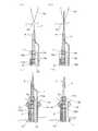
また、図3(a)に示すように、本実施形態においては長尺なプローブ1において、電源部4と連結している側を基端、その反対側であり人体内に挿入する側を末端とする。以下に説明するアンテナ部5及び内視鏡2についても同様である。 Further, as shown in FIG. 3A, in the present embodiment, in the
図3(a)(b)にて図示したプローブ1は、マイクロ波にて患部34を加温するための加温部5aを有するアンテナ部5と、前記アンテナ部5に設けられた造影部12a(末端側),12b(基端側)(以降、まとめて12とも言う)と、を備えている。 The
本実施形態のプローブ1は、このアンテナ部5、加温部5a及び造影部12に加え、さらに好ましくは、このアンテナ部5にて加温される温度を測定する測温部6と、前記アンテナ部5における前記加温部5aを前記患部34へと導くための誘導部7と、前記誘導部7に沿った方向へと前記アンテナ部5の移動方向を規定する方向規定部8と、を備えた構成になっている。
本実施形態においては、上述の構成を有するプローブ1について説明する。The
In the present embodiment, the
<3.マイクロ波プローブの各部の詳細>
1)アンテナ部
アンテナ部5は、同軸ケーブルにより構成される。そしてこのアンテナ部5には、患部34を加温するための加温部5aと、アンテナ部5の長手方向における加温部5aの加温範囲を示す造影部12とが設けられている。<3. Details of each part of microwave probe>
1) Antenna part
The antenna unit 5 is configured by a coaxial cable. The antenna unit 5 is provided with a
この同軸ケーブルは、図3(c)に示すように、断面において同心円の中心が同一である長尺の内部導体51、その外側に設けられた絶縁体52、その外側に設けられた外部導体53、その外側に設けられた外部絶縁体54、この外部絶縁体54を被覆する外部被覆55からなる。 As shown in FIG. 3 (c), the coaxial cable includes a long
なお、アンテナ部5の外部被覆55には、滅菌自在な材料が用いられている。こうすることにより、プローブ1を繰り返し使用しやすくなる。ここで挙げた外部被覆55を設けない場合は、外部絶縁体54において滅菌自在な材料を用いても良い。 The
なお、アンテナ部5の末端部9は、以下のような構成としている。すなわち、アンテナ部5の末端の外部絶縁体54及び外部被覆55を除去し、外部導体53を露出させる。そして、この末端に対し、先端が先細りのテーパー形状であって高分子樹脂からなるキャップを嵌めている。このようにして、アンテナ部5の末端部9を形成する。 The
i.加温部
次に、アンテナ部5に設けられた加温部5aについて説明する。
加温部5aは、図3(a)(b)に示すように、同軸ケーブルに設けられたスリット5aにより構成される。i. Next, the
As shown in FIGS. 3A and 3B, the
このスリット5aの作製方法としては、この同軸ケーブルの一部の全周において外部導
体53、外部絶縁体54及び外部被覆55を除去し、外部導体53の一部を短絡させるためのスリット5aを形成する。このスリット5aにより、短絡した外部導体53からマイクロ波が放射される。このマイクロ波により、患部34が所定の温度に加温される。
なおこのスリット5aの数は、図2に示すように1つだけでも良いし、患部34が複数箇所か否か、患部34の範囲等に応じて複数設けてもよい。As a method of manufacturing the
The number of
ii.造影部
次に、本実施形態において加温範囲を示す造影部12について説明する。
造影部12は、図3(a)(b)に示すように、加温部5aとなるスリット5aとは別に、同軸ケーブルに設けられたスリットに充填されたX線造影部材により構成される。ii. Contrast part
Next, the
As shown in FIGS. 3A and 3B, the
なお、この造影部12のためのスリットは、この同軸ケーブルの一部の全周において外部絶縁体54を除去することにより形成される。このスリットに、X線造影部材を充填する。そして、その上から外部被覆55を設ける。 The slit for the
なお、ここで挙げたX線造影部材としては公知のもので良く、例えば金が挙げられる。 The X-ray contrast member mentioned here may be a well-known member, for example, gold.
また、造影部12a,12bは、前記アンテナ部5の長手方向において、前記加温部5aを略中心としながら前記加温部5aを挟み、前記加温部5aから0mmを上回りかつ10mm以下離れて、末端方向及び基端方向それぞれ2箇所に設けられている。 The
このような構成によれば、まず、前記加温部5aを挟むように造影部12a,12bを予め配置させることにより、加温部5aにより適切に加温できる範囲が患者の体外から認識することができる。 According to such a configuration, first, by arranging the
なお、この加温範囲は、少なくともアンテナ部の長手方向での範囲である。また、この加温範囲は、加温部5aすなわちスリット部5a直近では加温の程度が大きく、スリット部5aから離れると加温の程度が小さい。 In addition, this heating range is a range at least in the longitudinal direction of the antenna portion. In addition, in this heating range, the degree of heating is large in the immediate vicinity of the
このように加温の程度に大小があるとしても、アンテナ部の長手方向において、造影部12で挟まれる範囲が、適切に加温できる範囲となる。 Thus, even if the degree of heating is large or small, the range sandwiched between the
そして、造影部12が示す加温範囲に患部34全体が入るように、加温部5aを患部34に配置することができる。その結果、患部34に対して確実に温熱治療を行うことができる。 And the
さらに、造影部12が示す加温範囲の略中心を加温部5aとしているため、患部34全体を加温範囲内に入れつつも、患部内における最も加温の程度を高めたい場所へと容易に加温部5a(即ちスリット5a)をピンポイントに配置することができる。 In addition, since the
さらに、図6に示すように、患部34における血管35に起因する熱伝導性を考慮にいれて、加温範囲の略中心以外の箇所を加温部5aとしても良い。具体的には、患部34全体を加温範囲内に入れつつも、大径の血管35がある部分に加温部5aが配置されるようにすれば、加温が不足することもなくなる 。 Furthermore, as shown in FIG. 6, in consideration of thermal conductivity due to the
また、造影部12を設ける際の加温部5aからの距離であるが、0mmを上回る、即ち加温部5aから離すことにより、加温部のスリット5aの短絡を維持することができ、確実にマイクロ波を放射させることができ、ひいては確実に加温機能を発揮させることができる。 Moreover, although it is the distance from the
一方、加温部5aから10mm以下の範囲で離すことにより、加温機能を確実に維持できる領域を示すことができる。 On the other hand, the area | region which can maintain a heating function reliably can be shown by separating | separating from the
なお、加温範囲の略中心以外の箇所を加温部5aとすることに伴い、加温部5aから造影部12a,12bまでの距離を互いに異ならせても良い。 It should be noted that the distance from the
例えば、造影部12a付近に大径の血管35が多く存在することになる患部を加温する場合、造影部12aと加温部5aとの間の加温の度合いは低下してしまい、実質的には加温部5a直近でしか適切な加温ができなくなる。それを反映させて、加温部5aと造影部12aとの間の距離を短くしても良い。 For example, when warming an affected part where many large-
2)測温部
次に、加温部5aにおいて加温された温度を測定するための測温部6について説明する。
この測温部6は、熱電対と、ファイバー型温度計と、超音波センサのいずれかから構成されている。2) Temperature measuring unit Next, the
The
熱電対6は、熱電能の異なる二種類の金属を接合した温度センサであり、2つの接合点を異なる温度にすると一定の方向に電流が流れ、熱起電力が生じる現象(ゼーベック効果)を利用した温度センサである。 The
本実施形態においては、この熱電対6が長尺なものを使用する。そして熱電対6の末端が前記スロットに位置させながら、アンテナ部5の外部被覆55に沿わせて配置する。さらに、この熱電対6とアンテナ部5(即ち加温部5a及び造影部12)とをテフロン(登録商標)樹脂でコーティングし、熱収縮チューブ11からなる最外部被覆11を形成する。 In the present embodiment, a
この熱電対6の代わりに、ファイバー型温度計や超音波センサを設けてもよい。また、熱電対6と共にこれらを設けてもよい。 Instead of the
上述した測温部6により、スリット5a近傍の温度の値が測定される。そしてこの測定された温度の値を、図2及び図3に示す温熱治療装置の制御部3に伝達する。そして、前記制御部3に設けられた温度補正手段により、前記温度情報における温度と、前記制御部3により制御される所定の温度との差を補正するために電源部4の出力を変動させる。 A temperature value near the
この温度補正手段により、所定の温度よりも患部34が加温され、正常な組織が死滅することを抑制することができる。また、患部34への加温が充分でないといった不具合を解消することができる。 By this temperature correction means, it is possible to prevent the
なお、この熱電対6やファイバー型温度計や超音波センサは、各々複数設けてもよいし、各種一つずつ設けてもよい。ただ、プローブ1の柔軟性を向上させるという点では、いずれか1つだけ設けるのが好ましい。 Note that a plurality of
なお、電源部4とアンテナ部5との間、及び電源部4と測温部6との間を連結するコネクタ10には、滅菌自在な材料が用いられている。アンテナ部5及び測温部6に、このコネクタ10が設けられることにより、プローブ1を繰り返し使用しやすくなる。
なお、制御部3とアンテナ部5との間、及び制御部3と測温部6との間についても、同様のコネクタ10を用いても良い。A sterilizable material is used for the
The
3)誘導部
次に、アンテナ部5における前記加温部5aを前記患部34へと導くための誘導部7について説明する。3) Guide part Next, the
この誘導部7は、人体組織に与える影響が少ない金属製の長尺なガイドワイヤー7により構成されている。また、このガイドワイヤー7は、アンテナ部5に対して自在に相対移動する。 The
ガイドワイヤー7の機能についてであるが、本実施形態に係るアンテナ部5をファーター乳頭部33へと挿入する方法を示す図4に示すように、まず、アンテナ部5と共にこのガイドワイヤー7を経口にて体内に挿入させ、胆道32の乳頭部33手前まで進行させる(図4(a))。 As for the function of the
そして、このガイドワイヤー7のみを、乳頭部33から胆道32へと先行して挿入させる(図4(b))。ガイドワイヤー7が乳頭部33から挿入されることにより、次にアンテナ部5を乳頭部33から胆道32内へと挿入しやすくなる。 Then, only this
このとき、ガイドワイヤー7に高周波ナイフ(図示せず)を設けてもよい。高周波ナイフを設けることにより、ガイドワイヤー7の末端が乳頭部33を通り抜けた後、高周波ナイフにより乳頭部33の孔を広げることができる。その結果、アンテナ部5の挿入がさらに容易になる。
なお、このときの高周波ナイフの周波数は、術語、乳頭部33に影響が残らない程度の周波数であればよい。At this time, a high-frequency knife (not shown) may be provided on the
The frequency of the high-frequency knife at this time may be a frequency that does not affect the terminology and the
ところで、ガイドワイヤー7が胆道32内へ挿入した後、アンテナ部5を同じく乳頭部33から胆道32内へと挿入するためには、アンテナ部5をガイドワイヤー7に沿わせる必要がある。すなわち、アンテナ部5を進行させる方向を規定する必要がある。このアンテナ部5の進行方向を、以下の方向規定部8により定める。 By the way, after the
4)方向規定部
以下、前記誘導部7(ガイドワイヤー7)に沿った方向へと前記アンテナ部5の移動方向を規定する方向規定部8について、図3(b)及び図4を用いて説明する。4) Direction defining portion Hereinafter, the
本実施形態における方向規定部8は、アンテナ部5における末端部9に設けられた誘導部挿通孔8(ガイドワイヤー挿通孔8)である。図3(b)に示すように、このガイドワイヤー挿通孔8は末端部9を貫通する孔であり、孔の出入口の一つは末端部9の側面に設けられており、もう一つの出入口は、末端部9の最も末端の部分に設けられている。以下、このガイドワイヤー挿通孔8の機能について述べる。 The
まず先にも述べたように、ガイドワイヤー7を乳頭部33から胆道32内へと挿入する。このとき、ガイドワイヤー7は、アンテナ部5の一部である末端部9に設けられたガイドワイヤー挿通孔8を貫通している。 First, as described above, the
そして、ガイドワイヤー7を胆道32内へと挿入した後、このガイドワイヤー7に沿って、アンテナ部5を胆道32内へと移動させる。この際、アンテナ部5の一部である末端部9をガイドワイヤー7が貫通していることから、アンテナ部5の進行方向はガイドワイヤー7の進行方向へと規定される(図4(c))。 Then, after inserting the
その後、アンテナ部5を患部34近傍に配置させる。必要ならば、アンテナ部5を患部34近傍に配置させた後、ガイドワイヤー7のみを基端側へと引き抜き、内視鏡2内に収納する(図4(d))。 Thereafter, the antenna unit 5 is disposed in the vicinity of the
以上、本実施形態におけるマイクロ波プローブ1について述べた。
次に、このマイクロ波プローブ1により内部を挿通されている内視鏡2について、温熱治療の方法、そして造影部12による加温範囲の確認方法と共に説明する。The
Next, the
<4.内視鏡及びマイクロ波プローブの使用方法の説明>
本実施形態における内視鏡2は、上述のマイクロ波プローブ1を挿通自在とできるものである必要がある。<4. Description of how to use endoscope and microwave probe>
The
さらに、本実施形態に係る内視鏡の概略斜視図である図5に示すように内視鏡2の末端部9には、乳頭部33へのガイドワイヤー7及び/又はアンテナ部5(以降、アンテナ部5等という)の挿入の様子を確認するための撮影部21、撮影部21よる撮影に必要な明かりを提供する照明部22、アンテナ部5等の進行方向を所望の方向に変化させる起上部23が設けられている。 Furthermore, as shown in FIG. 5 which is a schematic perspective view of the endoscope according to the present embodiment, the
この撮影部21は乳頭部33の様子を映し出すことができる程度の精度を有していれば良く、照明部22はこの撮影が可能な程度の明かりを提供できれば良い。この撮影部21及び照明部22は、先に述べた電源部4から電源が供給され、制御部3により動作が制御される。 The photographing
また、起上部23は内視鏡2の内部に設けられており、撮影部21及び照明部22と同じく、電源部4から電源が供給され、制御部3により動作が制御される。 The raising
具体的には、マイクロ波プローブ1を内部に有する内視鏡2が経口により挿入後、胆道32及び乳頭部33手前の十二指腸31に至るまでは、この起上部23は折りたたまれた状態で内視鏡2内に収納されている。 Specifically, after the
そして、乳頭部33近傍へと近づいたとき、図1にも示すように、この起上部23を制御部3により操作して起立させる。そして、十二指腸31の側壁にある乳頭部33の方向にアンテナ部5等が向かうように調整する。
そして、照明部22にて乳頭部33近傍を照らしながら、アンテナ部5等を挿入する様子を撮影部21にて撮影する。
このように撮影しながら、術者は乳頭部33の孔からアンテナ部5等を挿入する。And when approaching the
Then, while the
The operator inserts the antenna unit 5 and the like through the hole of the
その後、ガイドワイヤー7を乳頭部33の孔から胆道32内へと挿入する(図4(a)(b))。それに引き続いて、アンテナ部5を、末端部9に設けられたガイドワイヤー挿通孔8によって、ガイドワイヤー7に沿って移動させる。そして、テーパー形状及び可撓性を有する末端部9から乳頭部33の孔へと挿入する。そして、アンテナ部5におけるスリット5aを患部34近傍へと配置する(図4(c))。 Thereafter, the
このスリット5aの配置の際において、本実施形態におけるX線吸収部材が役に立つ。すなわち、スリット5aの配置の際、患者の体外から患部近傍に向けてX線を放射する。そして、図示しない観察装置にて、患者の体内における患部近傍を撮影する。 In arranging the
こうすることにより、観察装置には、X線を吸収した造影部が表示される。その結果、アンテナ部5における加温領域を観察装置にて確認することができ、リアルタイム観察装置ならば、術者がスリット5aの位置を確認しながらアンテナ部5の配置を行うことができる。 By doing so, a contrast unit that has absorbed X-rays is displayed on the observation apparatus. As a result, the heating region in the antenna unit 5 can be confirmed by the observation device, and if it is a real-time observation device, the operator can place the antenna unit 5 while confirming the position of the
アンテナ部5の配置が終了次第、ガイドワイヤー7を基端方向に引き抜き、内視鏡2内
に収納する。こうして、アンテナ部5を胆道32内に残し、アンテナ部5のスリット5aにより患部34を加温し、温熱治療を行う(図4(d))。As soon as the arrangement of the antenna unit 5 is completed, the
<5.実施の形態の効果に関する説明>
本実施形態におけるマイクロ波プローブ1及び温熱治療装置は以下の効果を奏する。<5. Explanation regarding effects of the embodiment>
The
即ち、アンテナ部の長手方向における前記加温部の加温範囲を示す造影部がアンテナ部に設けられることにより、以下の効果を奏する。
1.加温部の配置を患部近傍へと確実に行うことができる。
2.患部内での熱伝導性の違いが存在しようとも、患部全体を適切に加温することができる。
3.加温部が加温部としての能力を発揮できつつ、加温範囲を把握することができる。That is, by providing the antenna unit with the contrast unit indicating the heating range of the heating unit in the longitudinal direction of the antenna unit, the following effects can be obtained.
1. Arrangement of the heating part can be reliably performed in the vicinity of the affected part.
2. Even if there is a difference in thermal conductivity within the affected area, the entire affected area can be appropriately heated.
3. The warming range can be understood while the ability of the warming part can be demonstrated as the warming part.
その結果、加温範囲を示すように造影部が配置され、乳頭部を切開するまでもなく、加温部を患部へと容易に配置できる。そして、患部内にて熱伝導性に違いがあろうとも、適切に患部全体を加温できる。 As a result, the contrast unit is disposed so as to indicate the warming range, and the warming unit can be easily disposed on the affected part without incising the nipple. And even if there is a difference in thermal conductivity in the affected area, the entire affected area can be appropriately heated.
その結果、患部の加温不足による再治療は不要となり、術者だけでなく患者の負担も軽減することができる。 As a result, re-treatment due to insufficient heating of the affected area becomes unnecessary, and the burden on not only the operator but also the patient can be reduced.
なお、本実施形態に係るマイクロ波プローブは、胆道の腫瘍の治療以外にも、患部に至るまでに括約筋のような挿入困難な部位が存在する場合においても適用可能であるのは言うまでもない。 Needless to say, the microwave probe according to the present embodiment can be applied to a case where there is a difficult-to-insert part such as a sphincter before reaching the affected part, in addition to the treatment of a biliary tract tumor.
(実施の形態2)
本発明の技術的範囲は上述した実施の形態に限定されるものではなく、発明の構成要件やその組み合わせによって得られる特定の効果を導き出せる範囲において、種々の変更や改良を加えた形態も含む。
以下、実施の形態1の変形例について詳述する。(Embodiment 2)
The technical scope of the present invention is not limited to the above-described embodiments, and includes various modifications and improvements as long as the specific effects obtained by the constituent elements of the invention and combinations thereof can be derived.
Hereinafter, a modification of the first embodiment will be described in detail.
実施の形態1においては、造影部12として、X線造影部材がスリットに充填されていた。本実施形態においては、この造影部12の変形例について説明する。 In the first embodiment, the X-ray contrast member is filled in the slit as the
まず、造影部12としては、X線造影部材でなくとも、患部34外からのエネルギーを吸収して造影する部材であれば良い。
つまり、温熱治療中に、アンテナ部5の配置を確認できるように術者が患者の体外から患部へとエネルギーを放射し、そのエネルギーを吸収して造影可能な部材であれば良い。赤外線による熱エネルギーを患者の体外から与えることにより、造影部12を造影させても良い。First, the
That is, any member can be used as long as it allows the operator to radiate energy from outside the patient's body to the affected area and absorb the energy so that the arrangement of the antenna unit 5 can be confirmed during the thermal treatment. The
なお、本願明細書において「造影」という言葉は、X線による造影のみならず、造影部12の像を得ることができ、体外から観察したときに造影部12の位置が赤外線吸収等により判別可能となる状態を含むものとする。体外から観察したときの具体的な判別手段としては、この造影部12の像を、体外に設置したモニターに表示されるようにしても良い
。In the present specification, the term “contrast” means that not only X-ray contrast but also an image of the
なお、X線や赤外線による造影以外にも、CTスキャン、MRI(Magnetic Resonance Imaging system(磁気共鳴画像装置))、超音波等を用いて造影部12の像を得ても良い。 In addition to contrast enhancement using X-rays or infrared rays, an image of the
MRIを用いて造影部12の像を得る場合、MRIの信号を増強させる造影部材としてガドリニウム、マンガン、鉄、クロムなどの金属によるMRI造影剤を適用できる。 When an image of the
超音波を用いて造影部12の像を得る場合、体外から超音波を照射しその反射を利用して像を得る。この場合、微細気泡が造影部材として働くことになるため、造影部12に微細泡を含有させる、又は、微細泡前駆体を含浸させる。具体的な手段としては、ガラクトースとパルミチン酸の混合物質に水を加えて微細泡を生じさせ、この微細泡を利用する手段が挙げられる。 When an image of the
また、造影するための部材をスリットに充填させなくとも、造影可能な量をスリットに設けても良い。 Further, an amount capable of contrasting may be provided in the slit without filling the slit with a member for contrasting.
更に、造影するための部材をスリット内に設けるのではなく、外部絶縁体54表面、外部被覆55表面、又は最外部被覆11表面に設けてもよい。具体的には、造影するための部材を薄膜化し、図7に示すように、その薄膜をこれらの上に貼り付けても良い。 Further, a member for imaging may be provided on the surface of the
なお、外部絶縁体54表面や外部被覆55表面に薄膜の造影部材を貼り付ける場合、造影部材の上から最外部被覆11等を設けても良い。この時、最外部被覆11等はX線等エネルギーを透過でき、造影部材が造影部12として機能を発揮できるのが好ましい。 When a thin film contrast member is attached to the surface of the
なお、この薄膜の造影部材は、スリット5aと同様に、同軸ケーブルの或る部分の全周に貼り付けても良いし、一部に貼り付けても良い(図7(a))。また、その形状も円形状でも矩形でも良い。この時、図7(b)に示すように、造影部12aと12bとで非対称な形状の薄膜を貼り付けても良い。
こうすることにより、例え一方の造影部しか患者の体外から判別できなくとも、判別可能な造影部から加温部5aの位置を概ね特定することが可能だからである。The thin-film contrast member may be attached to the entire circumference of a certain part of the coaxial cable, or may be attached to a part, like the
By doing so, even if only one of the contrast sections can be discriminated from the outside of the patient's body, the position of the
更には、加温部であるスリット5aから加温範囲全体に至るまで、この薄膜を貼り付けても良い(図7(c))。
こうすることにより、患者の体外から加温範囲を明確に判別することができる。Furthermore, this thin film may be pasted from the
By doing so, it is possible to clearly determine the heating range from outside the patient's body.
実施の形態1のようにスリットに造影部材を充填させる場合、加温部としてのスリット5aの短絡を維持するため、これらのスリットはスリット5aから離さなければならない。 When the contrast member is filled in the slits as in the first embodiment, these slits must be separated from the
ところが、造影部材を薄膜化することにより、少なくとも同軸ケーブル表面を見たときに、スリット5aから連続して加温範囲を示すことができる。
こうすることにより、術者はより正確にアンテナ部5を配置することができる。However, by reducing the thickness of the contrast member, it is possible to show the heating range continuously from the
By doing so, the operator can arrange the antenna unit 5 more accurately.
(実施の形態3)
実施の形態1のマイクロ波プローブ1に、更に吸引用チューブを設けてもよい。吸引用チューブを設けることにより、術中、人体組織から出血したとしても、少量の出血であればこのチューブから吸引して排出することができる。(Embodiment 3)
The
また、内視鏡2における撮影部21の撮影を妨害する膿等の体液であっても、このチューブから吸引して排出することができる。その結果、作業を中断することなく、温熱治療を行うことができる。 Further, even body fluid such as pus that obstructs photographing by the photographing
さらに、冷却液還流用チューブを設けてもよい。冷却液還流用チューブを設けることにより、アンテナ部5における加温部5aすなわちスリット5a近傍が所定の温度以上に加
温されそうになっても、冷却液還流用チューブがスリット5a近傍の温度を下げることができ、異常加温による正常細胞の死滅を抑制することができる。Further, a coolant reflux tube may be provided. By providing the cooling liquid recirculation tube, the cooling liquid recirculation tube lowers the temperature in the vicinity of the
具体的には、吸引用チューブと冷却液還流用チューブは長尺なものを使用する。
そして冷却液還流用チューブは、測温部6に影響を与えない程度に距離を置きつつ、アンテナ部5の外部被覆55上に配置する。そして吸引用チューブは、この冷却液還流用チューブと平行させて配置する。
なお、吸引するための引き込み口は、プローブ1の末端部9に設けてもよいし、側面部に設けてもよい。Specifically, the suction tube and the cooling liquid reflux tube are long.
The cooling liquid recirculation tube is disposed on the outer covering 55 of the antenna unit 5 while keeping a distance so as not to affect the
Note that the inlet for suction may be provided at the
(実施の形態4)
実施の形態1の加温部5aとなる同軸ケーブルのスリット5aに加え、別の加温部5aを設けてもよい。(Embodiment 4)
In addition to the
先に述べたように、患部34によっては近傍に太い血管35が存在し、マイクロ波で加温を行っても太い血管の血流によって熱が奪われ、加温が充分に行えない場合も想定される。 As described above, depending on the
その場合、マイクロ波を放出するアンテナ部5のスリット5aに加え、末端に電熱自在な部材を有する新たな熱源を、アンテナ部5(プローブ1)の最外部被覆11上に設けてもよい。
こうすることにより、太い血管35が近傍に存在する患部34であっても、充分な温熱治療を患部34に対して行うことができる。In that case, in addition to the
In this way, even if the
(付記)
以下、本実施の好ましい態様について付記する。(Appendix)
Hereinafter, preferred embodiments of the present embodiment will be additionally described.
[付記1]
本実施形態におけるマイクロ波プローブは更に、前記マイクロ波プローブの末端に設けられた、先細りのテーパー形状の末端部を具備し、
前記末端部は可撓性を有することを特徴とする。[Appendix 1]
The microwave probe according to the present embodiment further includes a tapered tapered end portion provided at the end of the microwave probe,
The end portion has flexibility.
[付記2]
前記マイクロ波プローブは更に、
前記アンテナ部における前記加温部を前記患部へと導くための誘導部であって、前記アンテナ部に対して自在に相対移動する誘導部と、
前記誘導部に沿った方向へと前記アンテナ部の移動方向を規定する方向規定部と、
を具備することを特徴とする。[Appendix 2]
The microwave probe further includes:
A guide part for guiding the heating part in the antenna part to the affected part, wherein the guide part freely moves relative to the antenna part;
A direction defining unit that defines a moving direction of the antenna unit in a direction along the guide unit;
It is characterized by comprising.
[付記3]
前記誘導部はガイドワイヤーであり、前記方向規定部は前記末端部に設けられたガイドワイヤー挿通孔であることを特徴とする。[Appendix 3]
The guide part is a guide wire, and the direction defining part is a guide wire insertion hole provided in the end part.
[付記4]
前記マイクロ波プローブには更に測温部が備えられており、前記測温部は、熱電対、ファイバー型温度計及び超音波センサのいずれか又はそれらの組み合わせを有することを特徴とする。[Appendix 4]
The microwave probe further includes a temperature measuring unit, and the temperature measuring unit includes any one of a thermocouple, a fiber thermometer, an ultrasonic sensor, or a combination thereof.
[付記5]
前記アンテナ部の外部被覆には、滅菌自在な材料が用いられていることを特徴とする。[Appendix 5]
A sterilizable material is used for the outer covering of the antenna portion.
[付記6]
前記電源部及び測温部に設けられたコネクタには、滅菌自在な材料が用いられていることを特徴とする。[Appendix 6]
A sterilizable material is used for the connectors provided in the power supply unit and the temperature measuring unit.
[付記7]
前記造影部は、前記患部外からのエネルギーを吸収して造影する薄膜部材であり、前記同軸ケーブルにおける前記外部絶縁体表面又は外部被覆に設けられたことを特徴とする
。[Appendix 7]
The contrast part is a thin film member that absorbs and contrasts energy from outside the affected part, and is provided on the surface of the external insulator or the outer covering of the coaxial cable.
.
1 ・・・マイクロ波プローブ
2 ・・・内視鏡
21 ・・・撮影部
22 ・・・照明部
23 ・・・起上部
3 ・・・制御部
4 ・・・電源部
5 ・・・アンテナ部
5a ・・・加温部(スリット)
51 ・・・内部導体
52 ・・・内部絶縁体
53 ・・・外部導体
54 ・・・外部絶縁体
55 ・・・外部被覆
56 ・・・キャップ
6 ・・・測温部(熱電対)
7 ・・・誘導部(ガイドワイヤー)
8 ・・・方向規定部(ガイドワイヤー挿通孔)
9 ・・・末端部
91 ・・・首振り部
10 ・・・コネクタ
11 ・・・最外部被覆(熱収縮チューブ)
12 ・・・造影部
31 ・・・十二指腸
32 ・・・胆道
33 ・・・ファーター乳頭部
34 ・・・患部
35 ・・・血管
100・・・アンテナDESCRIPTION OF
DESCRIPTION OF
7 ... Guide part (guide wire)
8 ... Direction defining part (guide wire insertion hole)
9 ... Terminal part 91 ...
DESCRIPTION OF
Claims (9)
Translated fromJapaneseマイクロ波アンテナからなるアンテナ部と、
患部を加温するために前記アンテナ部に設けられた加温部と、
前記アンテナ部の長手方向における前記加温部の加温範囲を示す、前記アンテナ部に設けられた造影部と、
を具備することを特徴とするマイクロ波プローブ。A microwave probe that can be inserted into and removed from an insertion channel of an endoscope,
An antenna unit composed of a microwave antenna;
A heating part provided in the antenna part for heating the affected part;
A contrast unit provided in the antenna unit, indicating a heating range of the heating unit in a longitudinal direction of the antenna unit;
A microwave probe comprising:
前記加温部は、前記同軸ケーブルの一部における外部導体及び外部絶縁体を除去することにより形成されたスリットからなり、
前記造影部は、前記同軸ケーブルの長手方向において前記スリットを挟んで前記同軸ケーブルに複数設けられた造影部材からなることを特徴とする請求項1又は2に記載のマイクロ波プローブ。The antenna portion is composed of a coaxial cable provided with an inner conductor, an inner insulator, an outer conductor and an outer insulator in order from the inner circumference side to the outer circumference side,
The heating part is composed of a slit formed by removing an outer conductor and an outer insulator in a part of the coaxial cable,
3. The microwave probe according to claim 1, wherein the contrast section includes a plurality of contrast members provided on the coaxial cable across the slit in a longitudinal direction of the coaxial cable.
内周側から外周側へと順に内部導体、内部絶縁体、外部導体及び外部絶縁体が設けられた同軸ケーブルからなるアンテナ部と、
患部を加温するために前記アンテナ部に設けられた加温部と、
前記アンテナ部の長手方向における前記加温部の加温範囲を示す、前記アンテナ部に設けられた造影部と、
を具備し、
前記加温部は、前記同軸ケーブルの一部における外部導体及び外部絶縁体を除去することにより形成されたスリットからなり、
前記造影部は、前記同軸ケーブルの或る部分における外部絶縁体の一部を除去することにより形成されたスリットに充填されたX線造影部材からなり、
更に前記造影部は、前記アンテナ部の長手方向において前記加温部を挟み、前記加温部から0mmを上回りかつ10mm以下離れて複数設けられることを特徴とするマイクロ波
プローブ。A microwave probe that can be inserted into and removed from an insertion channel of an endoscope,
An antenna unit composed of a coaxial cable provided with an inner conductor, an inner insulator, an outer conductor and an outer insulator in order from the inner circumference side to the outer circumference side;
A heating part provided in the antenna part for heating the affected part;
A contrast unit provided in the antenna unit, indicating a heating range of the heating unit in a longitudinal direction of the antenna unit;
Comprising
The heating part is composed of a slit formed by removing an outer conductor and an outer insulator in a part of the coaxial cable,
The contrast portion is composed of an X-ray contrast member filled in a slit formed by removing a part of an external insulator in a certain portion of the coaxial cable,
The microwave probe is further provided with a plurality of the contrasting portions sandwiching the warming portion in the longitudinal direction of the antenna portion, more than 0 mm and 10 mm or less from the warming portion.
Priority Applications (1)
| Application Number | Priority Date | Filing Date | Title |
|---|---|---|---|
| JP2010189966AJP2012045169A (en) | 2010-08-26 | 2010-08-26 | Microwave probe |
Applications Claiming Priority (1)
| Application Number | Priority Date | Filing Date | Title |
|---|---|---|---|
| JP2010189966AJP2012045169A (en) | 2010-08-26 | 2010-08-26 | Microwave probe |
Publications (1)
| Publication Number | Publication Date |
|---|---|
| JP2012045169Atrue JP2012045169A (en) | 2012-03-08 |
Family
ID=45900761
Family Applications (1)
| Application Number | Title | Priority Date | Filing Date |
|---|---|---|---|
| JP2010189966AWithdrawnJP2012045169A (en) | 2010-08-26 | 2010-08-26 | Microwave probe |
Country Status (1)
| Country | Link |
|---|---|
| JP (1) | JP2012045169A (en) |
Cited By (1)
| Publication number | Priority date | Publication date | Assignee | Title |
|---|---|---|---|---|
| CN108523990A (en)* | 2018-01-30 | 2018-09-14 | 张丽娜 | A kind of microwave ablation therapeutic equipment for treating fibroid |
- 2010
- 2010-08-26JPJP2010189966Apatent/JP2012045169A/ennot_activeWithdrawn
Cited By (2)
| Publication number | Priority date | Publication date | Assignee | Title |
|---|---|---|---|---|
| CN108523990A (en)* | 2018-01-30 | 2018-09-14 | 张丽娜 | A kind of microwave ablation therapeutic equipment for treating fibroid |
| CN108523990B (en)* | 2018-01-30 | 2020-08-07 | 青岛大学附属医院 | A microwave ablation apparatus for treating uterine fibroids |
Similar Documents
| Publication | Publication Date | Title |
|---|---|---|
| CN102781357B (en) | Interventional Ablation Device with Tissue Discrimination Capability | |
| US10271889B2 (en) | Apparatus and method for cooling a tissue volume during thermal therapy treatment | |
| US8870772B2 (en) | Method and system for tissue recognition | |
| US8939914B2 (en) | Radiometers and related devices and methods | |
| CA2642568C (en) | Ablation instruments and related methods | |
| EP3565493B1 (en) | Transperineal vapor ablation systems | |
| JP5909054B2 (en) | Energy applicator temperature monitoring to assess ablation size | |
| WO2011080712A1 (en) | Method and system for tissue recognition | |
| US20100228240A1 (en) | Apparatus and methods for the positioning of implantable leads | |
| JP6118435B2 (en) | Catheter for monitoring biological environment | |
| CN112638297B (en) | Endoscopic cancer treatment system | |
| JP4138468B2 (en) | Microwave surgical device | |
| JP2012045169A (en) | Microwave probe | |
| CN212729963U (en) | Heat ablation catheter and heat ablation device | |
| JP2022065216A (en) | Treatment method and treatment system | |
| CN206403801U (en) | A kind of puncture needle | |
| JP2011217960A (en) | Microwave probe and thermotherapeutic apparatus | |
| JP2011217961A (en) | Microwave probe and thermotherapeutic apparatus | |
| US20160095662A1 (en) | Energy-based surgical instrument including integrated nerve detection system | |
| JP2022065215A (en) | Treatment method and treatment system | |
| JP2022065214A (en) | Treatment method and treatment system | |
| JPH08332233A (en) | Electrode needle and ultrashort wave heating treatment device using the electrode needle | |
| JPH0956828A (en) | Applicator for hyperthermia | |
| JPH11267227A (en) | Medical treatment device | |
| JP2001046530A (en) | Clinical heating device |
Legal Events
| Date | Code | Title | Description |
|---|---|---|---|
| A300 | Withdrawal of application because of no request for examination | Free format text:JAPANESE INTERMEDIATE CODE: A300 Effective date:20131105 |