JP2012044144A - Method for processing substrate and apparatus for processing substrate - Google Patents
Method for processing substrate and apparatus for processing substrateDownload PDFInfo
- Publication number
- JP2012044144A JP2012044144AJP2011099529AJP2011099529AJP2012044144AJP 2012044144 AJP2012044144 AJP 2012044144AJP 2011099529 AJP2011099529 AJP 2011099529AJP 2011099529 AJP2011099529 AJP 2011099529AJP 2012044144 AJP2012044144 AJP 2012044144A
- Authority
- JP
- Japan
- Prior art keywords
- substrate
- hydrophobizing agent
- hydrophobizing
- film
- solvent
- Prior art date
- Legal status (The legal status is an assumption and is not a legal conclusion. Google has not performed a legal analysis and makes no representation as to the accuracy of the status listed.)
- Granted
Links
- 239000000758substrateSubstances0.000titleclaimsabstractdescription501
- 238000012545processingMethods0.000titleclaimsabstractdescription175
- 238000000034methodMethods0.000titledescription106
- 239000003795chemical substances by applicationSubstances0.000claimsabstractdescription392
- XLYOFNOQVPJJNP-UHFFFAOYSA-NwaterSubstancesOXLYOFNOQVPJJNP-UHFFFAOYSA-N0.000claimsabstractdescription97
- 238000003672processing methodMethods0.000claimsabstractdescription13
- 239000002904solventSubstances0.000claimsdescription192
- 239000007788liquidSubstances0.000claimsdescription109
- 238000001035dryingMethods0.000claimsdescription77
- 239000002184metalSubstances0.000claimsdescription77
- 229910052751metalInorganic materials0.000claimsdescription77
- 238000001704evaporationMethods0.000claimsdescription16
- 230000008020evaporationEffects0.000claimsdescription9
- 230000008569processEffects0.000description103
- XUIMIQQOPSSXEZ-UHFFFAOYSA-NSiliconChemical compound[Si]XUIMIQQOPSSXEZ-UHFFFAOYSA-N0.000description102
- 229910052710siliconInorganic materials0.000description102
- 239000010703siliconSubstances0.000description102
- 239000000126substanceSubstances0.000description49
- KFZMGEQAYNKOFK-UHFFFAOYSA-NIsopropanolChemical compoundCC(C)OKFZMGEQAYNKOFK-UHFFFAOYSA-N0.000description36
- 230000000903blocking effectEffects0.000description36
- 125000001165hydrophobic groupChemical group0.000description26
- 239000000243solutionSubstances0.000description22
- 230000007246mechanismEffects0.000description18
- 238000010586diagramMethods0.000description16
- 239000012528membraneSubstances0.000description15
- LFQSCWFLJHTTHZ-UHFFFAOYSA-NEthanolChemical compoundCCOLFQSCWFLJHTTHZ-UHFFFAOYSA-N0.000description14
- 150000001875compoundsChemical class0.000description14
- ATJFFYVFTNAWJD-UHFFFAOYSA-NTinChemical compound[Sn]ATJFFYVFTNAWJD-UHFFFAOYSA-N0.000description12
- 238000007865dilutingMethods0.000description11
- 239000002210silicon-based materialSubstances0.000description11
- 238000012360testing methodMethods0.000description11
- 150000001412aminesChemical class0.000description10
- OKKJLVBELUTLKV-UHFFFAOYSA-NMethanolChemical compoundOCOKKJLVBELUTLKV-UHFFFAOYSA-N0.000description9
- 230000000694effectsEffects0.000description9
- 229910004298SiO 2Inorganic materials0.000description8
- 230000007423decreaseEffects0.000description8
- 238000010790dilutionMethods0.000description7
- 239000012895dilutionSubstances0.000description7
- 125000000524functional groupChemical group0.000description7
- CSCPPACGZOOCGX-UHFFFAOYSA-NAcetoneChemical compoundCC(C)=OCSCPPACGZOOCGX-UHFFFAOYSA-N0.000description6
- LYCAIKOWRPUZTN-UHFFFAOYSA-NEthylene glycolChemical compoundOCCOLYCAIKOWRPUZTN-UHFFFAOYSA-N0.000description6
- 238000009835boilingMethods0.000description6
- 239000012159carrier gasSubstances0.000description6
- FFUAGWLWBBFQJT-UHFFFAOYSA-NhexamethyldisilazaneChemical compoundC[Si](C)(C)N[Si](C)(C)CFFUAGWLWBBFQJT-UHFFFAOYSA-N0.000description6
- 230000002209hydrophobic effectEffects0.000description6
- FDPIMTJIUBPUKL-UHFFFAOYSA-Npentan-3-oneChemical compoundCCC(=O)CCFDPIMTJIUBPUKL-UHFFFAOYSA-N0.000description6
- 229910021420polycrystalline siliconInorganic materials0.000description6
- 229920005591polysiliconPolymers0.000description6
- BDERNNFJNOPAEC-UHFFFAOYSA-Npropan-1-olChemical compoundCCCOBDERNNFJNOPAEC-UHFFFAOYSA-N0.000description6
- BOTDANWDWHJENH-UHFFFAOYSA-NTetraethyl orthosilicateChemical compoundCCO[Si](OCC)(OCC)OCCBOTDANWDWHJENH-UHFFFAOYSA-N0.000description5
- 238000007654immersionMethods0.000description5
- 150000002576ketonesChemical class0.000description5
- YCKRFDGAMUMZLT-UHFFFAOYSA-NFluorine atomChemical compound[F]YCKRFDGAMUMZLT-UHFFFAOYSA-N0.000description4
- VEXZGXHMUGYJMC-UHFFFAOYSA-NHydrochloric acidChemical compoundClVEXZGXHMUGYJMC-UHFFFAOYSA-N0.000description4
- 229910052731fluorineInorganic materials0.000description4
- 239000011737fluorineSubstances0.000description4
- 150000004767nitridesChemical class0.000description4
- 239000004065semiconductorSubstances0.000description4
- XNWFRZJHXBZDAG-UHFFFAOYSA-N2-METHOXYETHANOLChemical compoundCOCCOXNWFRZJHXBZDAG-UHFFFAOYSA-N0.000description3
- 125000001309chloro groupChemical groupCl*0.000description3
- 230000003247decreasing effectEffects0.000description3
- 239000004973liquid crystal related substanceSubstances0.000description3
- 239000008155medical solutionSubstances0.000description3
- LLHKCFNBLRBOGN-UHFFFAOYSA-Npropylene glycol methyl ether acetateChemical compoundCOCC(C)OC(C)=OLLHKCFNBLRBOGN-UHFFFAOYSA-N0.000description3
- 150000005846sugar alcoholsPolymers0.000description3
- 238000012546transferMethods0.000description3
- 235000012431wafersNutrition0.000description3
- XKRFYHLGVUSROY-UHFFFAOYSA-NArgonChemical compound[Ar]XKRFYHLGVUSROY-UHFFFAOYSA-N0.000description2
- ZAMOUSCENKQFHK-UHFFFAOYSA-NChlorine atomChemical compound[Cl]ZAMOUSCENKQFHK-UHFFFAOYSA-N0.000description2
- ROSDSFDQCJNGOL-UHFFFAOYSA-NDimethylamineChemical compoundCNCROSDSFDQCJNGOL-UHFFFAOYSA-N0.000description2
- 239000006087Silane Coupling AgentSubstances0.000description2
- 239000000460chlorineSubstances0.000description2
- 229910052801chlorineInorganic materials0.000description2
- 239000003085diluting agentSubstances0.000description2
- 239000007789gasSubstances0.000description2
- -1organosilane compoundChemical class0.000description2
- 150000003961organosilicon compoundsChemical class0.000description2
- 230000009257reactivityEffects0.000description2
- CZDYPVPMEAXLPK-UHFFFAOYSA-NtetramethylsilaneChemical compoundC[Si](C)(C)CCZDYPVPMEAXLPK-UHFFFAOYSA-N0.000description2
- IJGRMHOSHXDMSA-UHFFFAOYSA-NAtomic nitrogenChemical compoundN#NIJGRMHOSHXDMSA-UHFFFAOYSA-N0.000description1
- ZOXJGFHDIHLPTG-UHFFFAOYSA-NBoronChemical compound[B]ZOXJGFHDIHLPTG-UHFFFAOYSA-N0.000description1
- UFHFLCQGNIYNRP-UHFFFAOYSA-NHydrogenChemical compound[H][H]UFHFLCQGNIYNRP-UHFFFAOYSA-N0.000description1
- CBENFWSGALASAD-UHFFFAOYSA-NOzoneChemical compound[O-][O+]=OCBENFWSGALASAD-UHFFFAOYSA-N0.000description1
- GJWAPAVRQYYSTK-UHFFFAOYSA-N[(dimethyl-$l^{3}-silanyl)amino]-dimethylsiliconChemical compoundC[Si](C)N[Si](C)CGJWAPAVRQYYSTK-UHFFFAOYSA-N0.000description1
- 150000001298alcoholsChemical class0.000description1
- 238000013459approachMethods0.000description1
- 229910052786argonInorganic materials0.000description1
- 230000015572biosynthetic processEffects0.000description1
- 229910052796boronInorganic materials0.000description1
- 239000000919ceramicSubstances0.000description1
- 230000008859changeEffects0.000description1
- 238000001311chemical methods and processMethods0.000description1
- 238000006243chemical reactionMethods0.000description1
- 238000005229chemical vapour depositionMethods0.000description1
- 229910052802copperInorganic materials0.000description1
- 239000008367deionised waterSubstances0.000description1
- 229910021641deionized waterInorganic materials0.000description1
- 238000013461designMethods0.000description1
- ADTGAVILDBXARD-UHFFFAOYSA-Ndiethylamino(dimethyl)siliconChemical compoundCCN(CC)[Si](C)CADTGAVILDBXARD-UHFFFAOYSA-N0.000description1
- KZFNONVXCZVHRD-UHFFFAOYSA-Ndimethylamino(dimethyl)siliconChemical compoundCN(C)[Si](C)CKZFNONVXCZVHRD-UHFFFAOYSA-N0.000description1
- 229910001873dinitrogenInorganic materials0.000description1
- 238000007599dischargingMethods0.000description1
- 230000003028elevating effectEffects0.000description1
- 239000011521glassSubstances0.000description1
- JEGUKCSWCFPDGT-UHFFFAOYSA-Nh2o hydrateChemical compoundO.OJEGUKCSWCFPDGT-UHFFFAOYSA-N0.000description1
- DKAGJZJALZXOOV-UHFFFAOYSA-Nhydrate;hydrochlorideChemical compoundO.ClDKAGJZJALZXOOV-UHFFFAOYSA-N0.000description1
- 239000001257hydrogenSubstances0.000description1
- 229910052739hydrogenInorganic materials0.000description1
- 125000002887hydroxy groupChemical group[H]O*0.000description1
- 239000011261inert gasSubstances0.000description1
- 150000002500ionsChemical class0.000description1
- 238000004519manufacturing processMethods0.000description1
- 239000000203mixtureSubstances0.000description1
- 238000012986modificationMethods0.000description1
- 230000004048modificationEffects0.000description1
- QULMGWCCKILBTO-UHFFFAOYSA-Nn-[dimethylamino(dimethyl)silyl]-n-methylmethanamineChemical compoundCN(C)[Si](C)(C)N(C)CQULMGWCCKILBTO-UHFFFAOYSA-N0.000description1
- KAHVZNKZQFSBFW-UHFFFAOYSA-Nn-methyl-n-trimethylsilylmethanamineChemical compoundCN(C)[Si](C)(C)CKAHVZNKZQFSBFW-UHFFFAOYSA-N0.000description1
- 230000003287optical effectEffects0.000description1
- 230000002093peripheral effectEffects0.000description1
- 238000010129solution processingMethods0.000description1
- 125000000026trimethylsilyl groupChemical group[H]C([H])([H])[Si]([*])(C([H])([H])[H])C([H])([H])[H]0.000description1
Images


Landscapes
- Cleaning Or Drying Semiconductors (AREA)
- Formation Of Insulating Films (AREA)
Abstract
Translated fromJapaneseDescription
Translated fromJapaneseこの発明は、基板を処理する基板処理方法および基板処理装置に関する。処理対象となる基板には、たとえば、半導体ウエハ、液晶表示装置用基板、プラズマディスプレイ用基板、FED(Field Emission Display)用基板、光ディスク用基板、磁気ディスク用基板、光磁気ディスク用基板、フォトマスク用基板、セラミック基板、太陽電池用基板などが含まれる。 The present invention relates to a substrate processing method and a substrate processing apparatus for processing a substrate. Examples of substrates to be processed include semiconductor wafers, liquid crystal display substrates, plasma display substrates, FED (Field Emission Display) substrates, optical disk substrates, magnetic disk substrates, magneto-optical disk substrates, and photomasks. Substrate, ceramic substrate, solar cell substrate and the like.
半導体装置や液晶表示装置の製造工程では、半導体ウエハや液晶表示装置用ガラス基板などの基板がたとえば一枚ずつ処理される。具体的には、薬液が基板に供給されることにより、基板の表面が薬液によって処理される。その後、純水が基板に供給されることにより、基板に付着している薬液が洗い流される。薬液が洗い流された後は、水よりも沸点が低いIPA(イソプロピルアルコール)が基板に供給され、基板に付着している純水がIPAに置換される。その後、基板が高速回転されることにより、基板に付着しているIPAが基板から除去され、基板が乾燥する。 In the manufacturing process of a semiconductor device or a liquid crystal display device, a substrate such as a semiconductor wafer or a glass substrate for a liquid crystal display device is processed, for example, one by one. Specifically, the surface of the substrate is treated with the chemical solution by supplying the chemical solution to the substrate. Thereafter, pure water is supplied to the substrate, so that the chemical solution adhering to the substrate is washed away. After the chemical solution is washed away, IPA (isopropyl alcohol) having a boiling point lower than that of water is supplied to the substrate, and the pure water adhering to the substrate is replaced with IPA. Thereafter, when the substrate is rotated at a high speed, IPA adhering to the substrate is removed from the substrate, and the substrate is dried.
しかしながら、このような基板処理方法では、基板を乾燥させるときに、基板の表面に形成されたパターンが倒壊する場合がある。そのため、特許文献1では、パターンの倒壊を防止するために、基板の表面を疎水化させた後に乾燥させる方法が開示されている。具体的には、疎水化剤が基板に供給されることにより、基板の表面が疎水化される。その後、IPAが基板に供給され、基板に付着している疎水化剤がIPAに置換される。疎水化剤がIPAに置換された後は、純水が基板に供給されることにより、基板に付着しているIPAが、純水に置換される。その後、基板が高速回転されることにより、基板が乾燥する。 However, in such a substrate processing method, a pattern formed on the surface of the substrate may collapse when the substrate is dried. Therefore,
基板の表面を十分に疎水化させれば、パターンの倒壊を抑制することができる。しかしながら、基板の表面が十分に疎水化されていない場合には、パターンの倒壊を抑制することができない。すなわち、基板の表面が部分的にしか疎水化されていない場合や、基板に対する処理液の接触角が十分に大きくない場合には、基板を疎水化させた後に乾燥させても、パターンの倒壊を抑制することができない。 If the surface of the substrate is sufficiently hydrophobized, the collapse of the pattern can be suppressed. However, when the surface of the substrate is not sufficiently hydrophobized, the collapse of the pattern cannot be suppressed. In other words, if the surface of the substrate is only partially hydrophobized, or if the contact angle of the treatment liquid with respect to the substrate is not sufficiently large, the pattern collapses even if the substrate is hydrophobized and then dried. It cannot be suppressed.
また、基板に付着している処理液の表面張力が大きいと、この基板を乾燥させるときにパターンに加わる力が大きい。特許文献1記載の基板処理方法では、純水が付着している基板を乾燥させる。ところが、純水の表面張力が大きいから、基板を疎水化させても、パターンの倒壊を十分に抑制することができないことがある。さらに、疎水化された基板に純水を供給すると、基板の疎水性が低下することがある。 Further, when the surface tension of the processing liquid adhering to the substrate is large, a force applied to the pattern is large when the substrate is dried. In the substrate processing method described in
そこで、この発明の目的は、パターンの倒壊を抑制または防止することができる基板処理方法および基板処理装置を提供することである。 Accordingly, an object of the present invention is to provide a substrate processing method and a substrate processing apparatus capable of suppressing or preventing pattern collapse.
前記目的を達成するための請求項1記載の発明は、疎水化剤を基板(W)に供給して前記基板の表面を疎水化させる疎水化工程(S104、S108、S204、S207)と、前記疎水化工程が行われた後に前記基板を乾燥させる乾燥工程(S106、S110、S205、S208)と、前記疎水化工程が終了してから前記乾燥工程が終了するまで、前記基板を水が接触しない状態に保つ工程とを含む、基板処理方法である。この基板処理方法において、基板の表面は、基板自体の表面であり、基板の表面にパターンが形成されている場合には、パターンの表面も含まれる。 In order to achieve the object, the invention according to
なお、この項において、括弧内の英数字は、後述の実施形態における対応構成要素の参照符号を表すものであるが、これらの参照符号により特許請求の範囲を限定する趣旨ではない。
この発明によれば、基板に疎水化剤が供給され、当該基板の表面が疎水化される。その後、基板が乾燥される。処理対象の基板は、疎水化されてから乾燥するまで水が接触しない状態に保たれる。したがって、疎水化剤が基板に供給された後に、水が接触することにより基板の疎水性が大幅に低下することを防止することができる。これにより、パターンの倒壊を抑制または防止することができる。In this section, alphanumeric characters in parentheses represent reference numerals of corresponding components in the embodiments described later, but the scope of the claims is not limited by these reference numerals.
According to this invention, the hydrophobizing agent is supplied to the substrate, and the surface of the substrate is hydrophobized. Thereafter, the substrate is dried. The substrate to be treated is kept in contact with water until it is hydrophobized and dried. Therefore, after the hydrophobizing agent is supplied to the substrate, it is possible to prevent the hydrophobicity of the substrate from greatly decreasing due to contact with water. Thereby, collapse of the pattern can be suppressed or prevented.
さらに、この基板処理方法において、基板は、請求項2記載の発明のように、金属膜を含む基板であってもよい。
この発明によれば、金属膜を含む基板に疎水化剤が供給され、当該基板の金属膜が疎水化される。その後、基板が乾燥される。処理対象の基板は、疎水化されてから乾燥するまで水が接触しない状態に保たれる。金属膜を疎水化させる疎水化剤によって疎水化された基板に水が接触すると、基板の疎水性が大幅に低下してしまう場合がある。したがって、このような疎水化剤が基板に供給された場合であっても、基板の疎水性が大幅に低下することを防止することができる。これにより、パターンの倒壊を抑制または防止することができる。Furthermore, in this substrate processing method, the substrate may be a substrate including a metal film, as in the second aspect of the invention.
According to this invention, the hydrophobizing agent is supplied to the substrate including the metal film, and the metal film on the substrate is hydrophobized. Thereafter, the substrate is dried. The substrate to be treated is kept in contact with water until it is hydrophobized and dried. When water contacts a substrate hydrophobized by a hydrophobizing agent that hydrophobizes the metal film, the hydrophobicity of the substrate may be greatly reduced. Therefore, even when such a hydrophobizing agent is supplied to the substrate, it is possible to prevent the hydrophobicity of the substrate from being significantly reduced. Thereby, collapse of the pattern can be suppressed or prevented.
請求項3記載の発明は、前記疎水化工程は、前記疎水化剤の液体を前記基板に供給する工程(S104、S108)を含み、前記疎水化工程が行われた後であって前記乾燥工程が行われる前に、前記疎水化剤を溶解させることができ、かつ水より表面張力が小さい溶剤を前記基板に供給する乾燥前リンス工程(S105、S109)をさらに含む、請求項1または2に記載の基板処理方法である。 According to a third aspect of the present invention, the hydrophobizing step includes a step (S104, S108) of supplying the liquid of the hydrophobizing agent to the substrate, and after the hydrophobizing step is performed, the drying step The method further comprises a pre-drying rinsing step (S105, S109) for supplying a solvent that can dissolve the hydrophobizing agent and has a surface tension smaller than that of water to the substrate before the step is performed. It is a substrate processing method of description.
この発明によれば、疎水化剤の液体が基板に供給された後に、当該疎水化剤を溶解させることができる溶剤が基板に供給される。これにより、基板に付着している疎水化剤が溶剤に置換される。そして、溶剤が基板から除去され、基板が乾燥される。乾燥前リンス処理において基板に供給される溶剤は、水より表面張力が小さい。したがって、乾燥前リンス処理において水を含む液体が基板に供給される場合よりもパターンの倒壊を抑制または防止することができる。 According to this invention, after the liquid of the hydrophobizing agent is supplied to the substrate, the solvent capable of dissolving the hydrophobizing agent is supplied to the substrate. Thereby, the hydrophobizing agent adhering to the substrate is replaced with the solvent. The solvent is then removed from the substrate and the substrate is dried. The solvent supplied to the substrate in the pre-drying rinsing process has a surface tension smaller than that of water. Therefore, the collapse of the pattern can be suppressed or prevented as compared with the case where the liquid containing water is supplied to the substrate in the rinsing process before drying.
請求項4記載の発明は、前記疎水化工程は、前記疎水化剤の蒸気を前記基板に供給する蒸気供給工程(S204、S207)を含み、前記乾燥工程は、前記基板に付着している前記疎水化剤を蒸発させる蒸発工程(S205、S208)を含む、請求項1または2に記載の基板処理方法である。
この発明によれば、疎水化剤の蒸気が基板に供給される。基板に供給された疎水化剤の蒸気の一部は液滴に変化して、基板に付着する。しかし、この疎水化剤の液滴は短時間で蒸発して、基板から除去される。したがって、疎水化工程が行われた後に基板に付着している疎水化剤を蒸発させることにより基板を乾燥させることができる。これにより、基板を速やかに乾燥させて、基板の処理時間を短縮することができる。According to a fourth aspect of the present invention, the hydrophobizing step includes a vapor supplying step (S204, S207) for supplying the hydrophobizing agent vapor to the substrate, and the drying step adheres to the substrate. The substrate processing method according to
According to the present invention, the hydrophobizing agent vapor is supplied to the substrate. Part of the hydrophobizing agent vapor supplied to the substrate changes into droplets and adheres to the substrate. However, the hydrophobizing agent droplets evaporate in a short time and are removed from the substrate. Therefore, the substrate can be dried by evaporating the hydrophobizing agent adhering to the substrate after the hydrophobizing step. Thereby, the substrate can be dried quickly, and the processing time of the substrate can be shortened.
請求項5記載の発明は、基板を保持する基板保持手段(2)と、前記基板保持手段に保持された基板に疎水化剤を供給する疎水化剤供給手段(16、17、216、217)と、基板を乾燥させる基板乾燥手段(2)と、前記疎水化剤供給手段を制御することにより、疎水化剤を前記基板保持手段に保持された基板に供給して前記基板の表面を疎水化させる疎水化工程(S104、S108、S204、S207)を行い、前記基板乾燥手段を制御することにより、前記疎水化工程が行われた後に前記基板を乾燥させる乾燥工程(S106、S110、S205、S208)を行い、前記疎水化工程が終了してから前記乾燥工程が終了するまで、前記基板を水が接触しない状態に保つ工程を行う制御手段(22)とを備える、基板処理装置(1、201)である。この発明によれば、請求項1に関連して述べた効果と同様な効果を奏することができる。 The invention according to
請求項6記載の発明は、前記疎水化剤供給手段は、前記基板保持手段に保持された基板に前記疎水化剤の液体を供給する手段(16、17)を含み、前記疎水化剤を溶解させることができ、かつ水より表面張力が小さい溶剤を前記基板保持手段に保持された基板に供給する溶剤供給手段(18)をさらに含み、前記制御手段は、前記疎水化剤供給手段を制御することにより、前記基板保持手段に保持された基板に前記疎水化剤の液体を供給する工程(S104、S108)を含む前記疎水化工程を行い、前記溶剤供給手段を制御することにより、前記疎水化工程が行われた後であって前記乾燥工程が行われる前に、前記基板保持手段に保持された基板に前記溶剤を供給する乾燥前リンス工程(S105、S109)を行う、請求項5記載の基板処理装置である。この発明によれば、請求項3に関連して述べた効果と同様な効果を奏することができる。 According to a sixth aspect of the present invention, the hydrophobizing agent supply means includes means (16, 17) for supplying a liquid of the hydrophobizing agent to the substrate held by the substrate holding means, and dissolves the hydrophobizing agent. And a solvent supply means (18) for supplying a solvent having a surface tension lower than that of water to the substrate held by the substrate holding means, and the control means controls the hydrophobizing agent supply means. Accordingly, the hydrophobizing step including the steps (S104, S108) of supplying the liquid of the hydrophobizing agent to the substrate held by the substrate holding means is performed, and the hydrophobicity is controlled by controlling the solvent supply means. The rinsing step before drying (S105, S109) for supplying the solvent to the substrate held by the substrate holding means is performed after the step is performed and before the drying step is performed. Base It is a processing apparatus. According to the present invention, an effect similar to that described in relation to
請求項7記載の発明は、前記疎水化剤供給手段は、前記基板保持手段に保持された基板に前記疎水化剤の蒸気を供給する手段(216、217)を含み、前記制御手段は、前記疎水化剤供給手段を制御することにより、前記基板保持手段に保持された基板に前記疎水化剤の蒸気を供給する蒸気供給工程(S204、S207)を含む前記疎水化工程を行い、前記基板乾燥手段を制御することにより、前記基板保持手段に保持された基板に付着している前記疎水化剤を蒸発させる蒸発工程(S205、S208)を含む前記乾燥工程を行う、請求項5記載の基板処理装置である。この発明によれば、請求項4に関連して述べた効果と同様な効果を奏することができる。 The invention according to
以下では、本発明の実施の形態を、添付図面を参照して詳細に説明する。
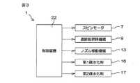
図1および図2は、それぞれ、本発明の第1実施形態に係る基板処理装置1の概略構成を示す模式図である。図3は、本発明の第1実施形態に係る基板処理装置1の電気的構成を説明するためのブロック図である。
基板処理装置1は、薬液やリンス液などの処理液によって半導体ウエハ等の基板Wを一枚ずつ処理する枚葉式の基板処理装置である。図1および図2に示すように、基板処理装置1は、基板Wを水平に保持して回転させるスピンチャック2(基板保持手段、基板乾燥手段)と、スピンチャック2の上方に配置された遮断板3と、スピンチャック2に保持された基板Wに処理液を供給する処理液供給機構4とを備えている。Hereinafter, embodiments of the present invention will be described in detail with reference to the accompanying drawings.
1 and 2 are schematic views each showing a schematic configuration of a
The
スピンチャック2は、たとえば、基板Wを挟持して保持する挟持式の基板保持機構である。スピンチャック2は、たとえば、水平に配置された円盤状のスピンベース5と、スピンベース5上に配置された複数個の挟持部材6と、スピンベース5に連結されたスピンモータ7とを含む。スピンチャック2は、各挟持部材6を基板Wの周端面に接触させること
により、基板Wを周囲から挟むことができる。さらに、スピンチャック2は、基板Wを保持した状態でスピンモータ7の駆動力をスピンベース5に入力することにより、基板Wの中心を通る鉛直な回転軸線まわりに基板Wを回転させることができる。スピンチャック2は、挟持式の基板保持機構に限らず、基板Wの下面(裏面)を吸着して保持するバキューム式などの他の形式の基板保持機構であってもよい。The
また、遮断板3は、たとえば、円板状である。遮断板3の直径は、たとえば、基板Wの直径とほぼ同じ、または基板Wの直径よりもやや大きい。遮断板3は、遮断板3の下面が水平になるように配置されている。さらに、遮断板3は、遮断板3の中心軸線がスピンチャック2の回転軸線上に位置するように配置されている。遮断板3の下面は、スピンチャック2に保持された基板Wの上面に対向している。遮断板3は、水平な姿勢で支軸8の下端に連結されている。遮断板3および支軸8は、遮断板昇降機構9によって、鉛直方向に昇降される。遮断板昇降機構9は、遮断板3の下面がスピンチャック2に保持された基板Wの上面に近接する処理位置(図2に示す位置)と、処理位置の上方に設けられた退避位置(図1に示す位置)との間で遮断板3を昇降させる。 Moreover, the blocking
また、処理液供給機構4は、薬液ノズル10と、薬液供給配管11と、薬液バルブ12とを含む。薬液供給配管11は、薬液ノズル10に接続されている。薬液バルブ12は、薬液供給配管11に介装されている。薬液バルブ12が開かれると、薬液供給配管11から薬液ノズル10に薬液が供給される。また、薬液バルブ12が閉じられると、薬液供給配管11から薬液ノズル10への薬液の供給が停止される。薬液ノズル10は、ノズル移動機構13に連結されている。ノズル移動機構13は、スピンチャック2の上方に設けられた処理位置(図1に示す位置)と、処理位置から離れた位置に設けられた退避位置(図2に示す位置)との間で薬液ノズル10を移動させる。処理位置は、薬液ノズル10から吐出された薬液がスピンチャック2に保持された基板Wの上面中央部に供給されるように設定されている(図1参照)。 The processing
また、処理液供給機構4は、中心軸ノズル14と、処理液供給配管15とを含む。中心軸ノズル14は、遮断板3の中心軸線に沿って配置されている。中心軸ノズル14は、支軸8の内部で上下に延びている。中心軸ノズル14は、遮断板3および支軸8と共に昇降する。処理液供給配管15は、遮断板3の上方で中心軸ノズル14に接続されている。処理液供給配管15から中心軸ノズル14には、たとえば、疎水化剤、溶剤、およびリンス液などの処理液が供給される。中心軸ノズル14に供給された処理液は、中心軸ノズル14の下端から下方に吐出される。そして、中心軸ノズル14から吐出された処理液は、遮断板3の中央部を上下に貫通する貫通孔(図示せず)を通って、遮断板3の下面中央部から下方に吐出される(図2参照)。これにより、スピンチャック2に保持された基板Wの上面中央部に処理液が供給される。 The processing
処理液供給機構4は、2つの疎水化剤供給ユニット16、17と、溶剤バルブ18(溶剤供給手段)が介装された溶剤供給配管19と、リンス液バルブ20が介装されたリンス液供給配管21とを含む。処理液供給配管15は、各疎水化剤供給ユニット16、17、溶剤供給配管19、およびリンス液供給配管21に接続されている。第1疎水化剤供給ユニット16(疎水化剤供給手段)から処理液供給配管15には、第1疎水化剤(液体)が供給される。第2疎水化剤供給ユニット17(疎水化剤供給手段)から処理液供給配管15には、第2疎水化剤(液体)が供給される。また、溶剤バルブ18が開かれると、溶剤(液体)が、溶剤供給配管19から処理液供給配管15に供給される。同様に、リンス液バルブ20が開かれると、リンス液が、リンス液供給配管21から処理液供給配管15に供給される。 The treatment
リンス液は、水を含む液体である。リンス液は、たとえば、純水(脱イオン水)、炭酸
水、電解イオン水、水素水、オゾン水、および希釈濃度(たとえば、10〜100ppm程度)の塩酸水のいずれかである。
また、第1疎水化剤および第2疎水化剤は、互いに種類の異なる疎水化剤である。第1疎水化剤および第2疎水化剤は、水を含まない液体である。第1疎水化剤は、たとえば、シリコン自体およびシリコンを含む化合物を疎水化させるシリコン系疎水化剤、または金属自体および金属を含む化合物を疎水化させるメタル系疎水化剤である。第2疎水化剤についても同様である。The rinse liquid is a liquid containing water. The rinse liquid is, for example, any of pure water (deionized water), carbonated water, electrolytic ion water, hydrogen water, ozone water, and hydrochloric acid water having a diluted concentration (for example, about 10 to 100 ppm).
The first hydrophobizing agent and the second hydrophobizing agent are different types of hydrophobizing agents. The first hydrophobizing agent and the second hydrophobizing agent are liquids that do not contain water. The first hydrophobizing agent is, for example, a silicon hydrophobizing agent that hydrophobizes silicon itself and a compound containing silicon, or a metal hydrophobizing agent that hydrophobizes a compound containing metal itself and a metal. The same applies to the second hydrophobizing agent.
メタル系疎水化剤は、たとえば、疎水基を有するアミン、および有機シリコン化合物の少なくとも一つを含む。
シリコン系疎水化剤は、たとえば、シランカップリング剤である。シランカップリング剤は、たとえば、HMDS(ヘキサメチルジシラザン)、TMS(テトラメチルシラン)、フッ素化アルキルクロロシラン、アルキルジシラザン、および非クロロ系疎水化剤の少なくとも一つを含む。The metal hydrophobizing agent includes, for example, at least one of an amine having a hydrophobic group and an organosilicon compound.
The silicon hydrophobizing agent is, for example, a silane coupling agent. The silane coupling agent includes, for example, at least one of HMDS (hexamethyldisilazane), TMS (tetramethylsilane), fluorinated alkylchlorosilane, alkyldisilazane, and non-chlorohydrophobizing agent.
非クロロ系疎水化剤は、たとえば、ジメチルシリルジメチルアミン、ジメチルシリルジエチルアミン、ヘキサメチルジシラザン、テトラメチルジシラザン、ビス(ジメチルアミノ)ジメチルシラン、N,N−ジメチルアミノトリメチルシラン、N−(トリメチルシリル)ジメチルアミンおよびオルガノシラン化合物の少なくとも一つを含む。
また、溶剤は、疎水化剤および水を溶解させることができ、かつ水を含まない液体である。溶剤は、たとえば、アルコール、ケトン、PGMEA(プロピレングリコールモノメチルエーテルアセテート)、EGMEA(エチレングリコールモノメチルエーテル)、およびフッ素系溶剤の少なくとも一つを含む。溶剤は、水よりも表面張力が小さく、かつ水よりも沸点が低い。Non-chloro hydrophobizing agents include, for example, dimethylsilyldimethylamine, dimethylsilyldiethylamine, hexamethyldisilazane, tetramethyldisilazane, bis (dimethylamino) dimethylsilane, N, N-dimethylaminotrimethylsilane, N- (trimethylsilyl) ) Containing at least one of dimethylamine and an organosilane compound.
The solvent is a liquid that can dissolve the hydrophobizing agent and water and does not contain water. Examples of the solvent include at least one of alcohol, ketone, PGMEA (propylene glycol monomethyl ether acetate), EGMEA (ethylene glycol monomethyl ether), and a fluorine-based solvent. The solvent has a lower surface tension than water and a lower boiling point than water.
アルコールは、たとえば、メチルアルコール、エタノール、プロピルアルコール、およびIPA(イソプロピルアルコール)の少なくとも一つを含む。
ケトンは、たとえば、アセトン、およびジエチルケトンの少なくとも一つを含む。
フッ素系溶剤は、たとえば、HFE(ハイドロフルオロエーテル)、HFC(ハイドロフルオロカーボン)の少なくとも一つを含む。The alcohol includes, for example, at least one of methyl alcohol, ethanol, propyl alcohol, and IPA (isopropyl alcohol).
The ketone includes, for example, at least one of acetone and diethyl ketone.
The fluorine-based solvent includes, for example, at least one of HFE (hydrofluoroether) and HFC (hydrofluorocarbon).
図3に示すように、基板処理装置1は、制御装置22を備えている。スピンモータ7、遮断板昇降機構9、ノズル移動機構13、および各疎水化剤供給ユニット16、17は、制御装置22によって制御される。また、基板処理装置1に備えられた各バルブの開閉は、制御装置22によって制御される。図1に示すように、制御装置22は、スピンチャック2によって基板Wを回転させた状態で、薬液ノズル10を処理位置に位置させ、薬液ノズル10から薬液を吐出させる。薬液ノズル10から吐出された薬液は、スピンチャック2に保持された基板Wの上面中央部に供給される。そして、基板Wの上面中央部に供給された薬液は、基板Wの回転による遠心力を受けて基板W上を外方に広がっていく。これにより、基板Wの上面全域に薬液が供給され、基板Wが薬液によって処理される。 As shown in FIG. 3, the
一方、図2に示すように、制御装置22は、スピンチャック2によって基板Wを回転させた状態で、遮断板3を処理位置に位置させ、中心軸ノズル14から処理液を吐出させる。中心軸ノズル14から吐出された処理液は、スピンチャック2に保持された基板Wの上面中央部に供給される。そして、基板Wの上面中央部に供給された処理液は、基板Wの回転による遠心力を受けて基板W上を外方に広がっていく。これにより、基板Wの上面全域に処理液が供給され、基板Wが処理液によって処理される。また、遮断板3の下面が基板Wの上面に近接した状態で基板Wに処理液が供給されるので、基板Wの周囲に振り切られた処理液が跳ね返って基板Wに付着することが抑制または防止される。 On the other hand, as shown in FIG. 2, the
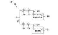
図4は、本発明の第1実施形態に係る第1疎水化剤供給ユニット16の概略構成を示す模式図である。以下では、第1疎水化剤供給ユニット16の概略構成について説明する。第2疎水化剤供給ユニット17の概略構成は、第1疎水化剤供給ユニット16と同様であるので、その説明を省略する。
第1疎水化剤供給ユニット16は、第1疎水化剤(液体)が貯留された第1タンク23と、希釈溶剤(液体)が貯留された第2タンク24とを含む。さらに、第1疎水化剤供給ユニット16は、第1タンク23に接続された第1配管25と、第2タンク24に接続された第2配管26と、第1配管25に介装された第1バルブ27および第1流量調整バルブ28と、第2配管26に介装された第2バルブ29および第2流量調整バルブ30と、第1配管25および第2配管26に接続された集合配管31とを含む。FIG. 4 is a schematic diagram showing a schematic configuration of the first hydrophobizing
The first hydrophobizing
第1タンク23に貯留された第1疎水化剤は、たとえば、ポンプによって吸引したり、第1タンク23内に気体を供給して第1タンク23内の気圧を上昇させたりすることにより、第1配管25に供給される。希釈溶剤についても同様である。集合配管31は、処理液供給配管15に接続されている(図1および図2参照)。また、第1バルブ27および第2バルブ29の開閉は、制御装置22によって制御される。また、第1流量調整バルブ28および第2流量調整バルブ30の開度は、制御装置22によって制御される。 The first hydrophobizing agent stored in the
制御装置22が、第1バルブ27を開くと、第1タンク23に貯留された第1疎水化剤が、第1流量調整バルブ28の開度に応じた流量で集合配管31に供給される。同様に、制御装置22が、第2バルブ29を開くと、第2タンク24に貯留された希釈溶剤が、第2流量調整バルブ30の開度に応じた流量で集合配管31に供給される。これにより、第1疎水化剤および希釈溶剤が、集合配管31内で混合される。そのため、希釈溶剤が第1疎水化剤に溶解し、第1疎水化剤が希釈される。そして、希釈された第1疎水化剤が、集合配管31から処理液供給配管15に供給され、中心軸ノズル14から吐出される。第1疎水化剤は、希釈された状態で中心軸ノズル14に供給されてもよいし、希釈されずに中心軸ノズル14に供給されてもよい。たとえば、第1疎水化剤が、メタル系疎水化剤の一例である有機シリコン化合物である場合には、第1疎水化剤は、希釈されずに中心軸ノズル14に供給されることが好ましい。 When the
希釈溶剤は、前述の疎水化剤および溶剤ならびに水を溶解させることができ、かつ水を含まない液体である。希釈溶剤は、たとえば、アルコール(一価アルコール)、多価アルコール、ケトン、PGMEA、EGMEA、およびフッ素系溶剤の少なくとも一つを含む。希釈溶剤は、水よりも表面張力が小さく、かつ水よりも沸点が低い。
アルコールは、たとえば、メチルアルコール、エタノール、プロピルアルコール、およびIPAの少なくとも一つを含む。The dilution solvent is a liquid that can dissolve the above-described hydrophobizing agent and solvent and water and does not contain water. The diluent solvent includes, for example, at least one of alcohol (monohydric alcohol), polyhydric alcohol, ketone, PGMEA, EGMEA, and fluorine-based solvent. The diluted solvent has a lower surface tension than water and a lower boiling point than water.
The alcohol includes, for example, at least one of methyl alcohol, ethanol, propyl alcohol, and IPA.
多価アルコールは、たとえば、エチレングリコールを含む。
ケトンは、たとえば、アセトン、およびジエチルケトンの少なくとも一つを含む。
フッ素系溶剤は、たとえば、HFE、HFCの少なくとも一つを含む。
第1疎水化剤が、メタル系疎水化剤の一例である疎水基を有するアミンである場合には、親水性溶媒が希釈溶剤として用いられる。すなわち、たとえば、メチルアルコール、エタノール、IPA、プロピルアルコールなどの一価アルコールや、エチレングリコールなどの多価アルコールや、アセトン、ジエチルケトンなどのケトンが、希釈溶剤として用いられる。The polyhydric alcohol includes, for example, ethylene glycol.
The ketone includes, for example, at least one of acetone and diethyl ketone.
The fluorine-based solvent includes, for example, at least one of HFE and HFC.
When the first hydrophobizing agent is an amine having a hydrophobic group, which is an example of a metal hydrophobizing agent, a hydrophilic solvent is used as a dilution solvent. That is, for example, monohydric alcohols such as methyl alcohol, ethanol, IPA, and propyl alcohol, polyhydric alcohols such as ethylene glycol, and ketones such as acetone and diethyl ketone are used as dilution solvents.
図5は、本発明の第1実施形態に係る基板処理装置1によって基板Wを処理するときの第1処理例について説明するための工程図である。以下では、図1、図2および図5を参照して、デバイス形成面である表面にパターンP(図7参照)が形成された基板Wを処理するときの処理例について説明する。また、以下の説明における「基板Wの上面(表面)
」は、基板W自体の上面(表面)およびパターンPの表面を含む。FIG. 5 is a process diagram for explaining a first processing example when the substrate W is processed by the
"Includes the upper surface (surface) of the substrate W itself and the surface of the pattern P.
未処理の基板Wは、図示しない搬送ロボットによって搬送され、デバイス形成面である表面をたとえば上に向けてスピンチャック2上に載置される。そして、制御装置22は、スピンチャック2を制御して、載置された基板Wを保持させる。基板Wがスピンチャック2上に搬送されるとき、制御装置22は、搬送ロボットおよび基板Wが薬液ノズル10および遮断板3に衝突することを防止するために、薬液ノズル10および遮断板3をそれぞれの退避位置に位置させている。 The unprocessed substrate W is transported by a transport robot (not shown), and placed on the
次に、薬液を基板Wに供給する薬液処理が行われる(S101)。具体的には、制御装置22は、ノズル移動機構13を制御して、遮断板3を退避位置に位置させた状態で、薬液ノズル10を退避位置から処理位置に移動させる。また、制御装置22は、スピンモータ7を制御して、スピンチャック2に保持された基板Wを回転させる。そして、制御装置22は、スピンチャック2によって基板Wを回転させながら、薬液ノズル10から基板Wの上面中央部に向けて薬液を吐出させる。これにより、基板Wの上面全域に薬液が供給され、基板Wが薬液によって処理される(薬液処理)。そして、薬液処理が所定時間にわたって行われると、制御装置22は、薬液バルブ12を閉じて薬液の吐出を停止させる。その後、制御装置22は、ノズル移動機構13を制御して、薬液ノズル10を退避位置に移動させる。 Next, a chemical process for supplying the chemical liquid to the substrate W is performed (S101). Specifically, the
次に、リンス液の一例である純水を基板Wに供給する水リンス処理(水リンス工程)が行われる(S102)。具体的には、制御装置22は、遮断板昇降機構9を制御して、薬液ノズル10を退避位置に位置させた状態で、遮断板3を退避位置から処理位置に移動させる。そして、制御装置22は、リンス液バルブ20を開いて、スピンチャック2によって基板Wを回転させながら、中心軸ノズル14から基板Wの上面中央部に向けて純水を吐出させる。これにより、基板Wの上面全域に純水が供給され、基板Wに付着している薬液が純水によって洗い流される(水リンス処理)。そして、水リンス処理が所定時間にわたって行われると、制御装置22は、リンス液バルブ20を閉じて純水の吐出を停止させる。 Next, the water rinse process (water rinse process) which supplies the pure water which is an example of the rinse liquid to the board | substrate W is performed (S102). Specifically, the
次に、溶剤を基板Wに供給する第1溶剤リンス処理(第1溶剤リンス工程)が行われる(S103)。具体的には、制御装置22は、溶剤バルブ18を開いて、遮断板3を処理位置に位置させ、さらに、スピンチャック2によって基板Wを回転させながら、中心軸ノズル14から基板Wの上面中央部に向けて溶剤を吐出させる。これにより、中心軸ノズル14から吐出された溶剤が、第1溶剤として基板Wの上面全域に供給される。前述のように、溶剤は、水を溶解させることができる液体であるから、基板Wに付着している純水は、基板Wに供給された溶剤に溶け込む。したがって、基板Wの上面全域に溶剤が供給されることにより、基板Wに付着している純水が、溶剤によって洗い流されて溶剤に置換される(第1溶剤リンス処理)。そして、第1溶剤リンス処理が所定時間にわたって行われると、制御装置22は、溶剤バルブ18を閉じて溶剤の吐出を停止させる。 Next, the 1st solvent rinse process (1st solvent rinse process) which supplies a solvent to the board | substrate W is performed (S103). Specifically, the
次に、第1疎水化剤(液体)を基板Wに供給する第1疎水化処理(疎水化工程)が行われる(S104)。具体的には、制御装置22は、第1疎水化剤供給ユニット16を制御することにより、遮断板3を処理位置に位置させ、さらに、スピンチャック2によって基板Wを回転させながら、中心軸ノズル14から基板Wの上面中央部に向けて第1疎水化剤を吐出させる。これにより、第1疎水化剤が基板Wの上面全域に供給される。前述のように、溶剤は、疎水化剤を溶解させることができる液体であるから、基板Wの上面全域に第1疎水化剤が供給されることにより、基板Wに付着している溶剤が、第1疎水化剤に置換される。これにより、第1疎水化剤がパターンPの内部にまで入り込んで、基板Wの上面が疎水化される(第1疎水化処理)。そして、第1疎水化処理が所定時間にわたって行われると、制御装置22は、第1疎水化剤供給ユニット16を制御して第1疎水化剤の吐出を停止させる。 Next, a first hydrophobizing process (hydrophobizing step) for supplying the first hydrophobizing agent (liquid) to the substrate W is performed (S104). Specifically, the
次に、溶剤を基板Wに供給する乾燥前リンス処理(乾燥前リンス工程)が行われる(S105)。具体的には、制御装置22は、溶剤バルブ18を開いて、遮断板3を処理位置に位置させ、さらに、スピンチャック2によって基板Wを回転させながら、中心軸ノズル14から基板Wの上面中央部に向けて溶剤を吐出させる。これにより、中心軸ノズル14から吐出された溶剤が、基板Wの上面全域に供給される。そのため、基板Wに付着している第1疎水化剤が、溶剤に置換される(乾燥前リンス処理)。そして、乾燥前リンス処理が所定時間にわたって行われると、制御装置22は、溶剤バルブ18を閉じて溶剤の吐出を停止させる。 Next, a pre-drying rinsing process (pre-drying rinsing step) for supplying the solvent to the substrate W is performed (S105). Specifically, the
次に、基板Wを乾燥させる乾燥処理(乾燥工程)が行われる(S106)。具体的には、制御装置22は、スピンモータ7を制御して、遮断板3を処理位置に位置させた状態で、基板Wを高回転速度(たとえば数千rpm)で回転させる。これにより、基板Wに付着している溶剤に大きな遠心力が作用して、溶剤が基板Wの周囲に振り切られる。このようにして、溶剤が基板Wから除去され、基板Wが乾燥する(乾燥処理)。そして、乾燥処理が所定時間にわたって行われた後は、制御装置22は、スピンモータ7を制御して、スピンチャック2による基板Wの回転を停止させる。さらに、制御装置22は、遮断板昇降機構9を制御して、遮断板3を処理位置から退避位置に移動させる。その後、処理済みの基板Wが搬送ロボットによってスピンチャック2から搬出される。 Next, a drying process (drying process) for drying the substrate W is performed (S106). Specifically, the
図6は、本発明の第1実施形態に係る基板処理装置1によって基板Wを処理するときの第2処理例について説明するための工程図である。以下では、図1、図2、および図6を参照して、デバイス形成面である表面にパターンPが形成された基板Wを処理するときの処理例について説明する。第2処理例では、2種類の疎水化剤が基板Wに供給される。第2処理例において、第1疎水化処理(S104)までの工程は第1処理例と同様であるので、第1処理例と同一の参照符号を付してその説明を省略する。したがって、以下では、第1疎水化処理が行われた後の工程について説明する。 FIG. 6 is a process diagram for explaining a second processing example when the substrate W is processed by the
第1疎水化処理(S104)が行われた後は、溶剤を基板Wに供給する第2溶剤リンス処理(第2溶剤リンス工程)が行われる(S107)。具体的には、制御装置22は、溶剤バルブ18を開いて、遮断板3を処理位置に位置させ、さらに、スピンチャック2によって基板Wを回転させながら、中心軸ノズル14から基板Wの上面中央部に向けて溶剤を吐出させる。これにより、中心軸ノズル14から吐出された溶剤が、第2溶剤として基板Wの上面全域に供給される。前述のように、溶剤は、疎水化剤を溶解させることができる液体であるから、基板Wの上面全域に溶剤が供給されることにより、基板Wに付着している第1疎水化剤が、溶剤に置換される(第2溶剤リンス処理)。そして、第2溶剤リンス処理が所定時間にわたって行われると、制御装置22は、溶剤バルブ18を閉じて溶剤の吐出を停止させる。 After the first hydrophobizing process (S104), a second solvent rinsing process (second solvent rinsing process) for supplying a solvent to the substrate W is performed (S107). Specifically, the
次に、第2疎水化剤(液体)を基板Wに供給する第2疎水化処理(疎水化工程)が行われる(S108)。具体的には、制御装置22は、第2疎水化剤供給ユニット17を制御することにより、遮断板3を処理位置に位置させ、さらに、スピンチャック2によって基板Wを回転させながら、中心軸ノズル14から基板Wの上面中央部に向けて第2疎水化剤を吐出させる。これにより、第2疎水化剤が基板Wの上面全域に供給される。前述のように、溶剤は、疎水化剤を溶解させることができる液体であるから、基板Wの上面全域に第2疎水化剤が供給されることにより、基板Wに付着している溶剤が、第2疎水化剤に置換される。これにより、第2疎水化剤がパターンPの内部にまで入り込んで、基板Wの上面が疎水化される(第2疎水化処理)。そして、第2疎水化処理が所定時間にわたって行われると、制御装置22は、第2疎水化剤供給ユニット17を制御して第2疎水化剤の吐出を停止させる。 Next, a second hydrophobizing process (hydrophobizing step) for supplying the second hydrophobizing agent (liquid) to the substrate W is performed (S108). Specifically, the
次に、溶剤を基板Wに供給する乾燥前リンス処理(乾燥前リンス工程)が行われる(S109)。具体的には、制御装置22は、溶剤バルブ18を開いて、遮断板3を処理位置に位置させ、さらに、スピンチャック2によって基板Wを回転させながら、中心軸ノズル14から基板Wの上面中央部に向けて溶剤を吐出させる。これにより、中心軸ノズル14から吐出された溶剤が、基板Wの上面全域に供給される。そのため、基板Wに付着している第2疎水化剤が、溶剤に置換される(乾燥前リンス処理)。そして、乾燥前リンス処理が所定時間にわたって行われると、制御装置22は、溶剤バルブ18を閉じて溶剤の吐出を停止させる。 Next, a pre-drying rinsing process (pre-drying rinsing step) for supplying the solvent to the substrate W is performed (S109). Specifically, the
次に、基板Wを乾燥させる乾燥処理(乾燥工程)が行われる(S110)。具体的には、制御装置22は、スピンモータ7を制御して、遮断板3を処理位置に位置させた状態で、基板Wを高回転速度(たとえば数千rpm)で回転させる。これにより、基板Wに付着している溶剤に大きな遠心力が作用して、溶剤が基板Wの周囲に振り切られる。このようにして、溶剤が基板Wから除去され、基板Wが乾燥する(乾燥処理)。そして、乾燥処理が所定時間にわたって行われた後は、制御装置22は、スピンモータ7を制御して、スピンチャック2による基板Wの回転を停止させる。さらに、制御装置22は、遮断板昇降機構9を制御して、遮断板3を処理位置から退避位置に移動させる。その後、処理済みの基板Wが搬送ロボットによってスピンチャック2から搬出される。 Next, a drying process (drying process) for drying the substrate W is performed (S110). Specifically, the
図7は、本発明の第1実施形態に係る基板処理装置1によって処理される基板Wの一例を示す断面図である。
基板処理装置1によって処理される基板Wは、たとえば、積層膜32のパターンPが形成された基板Wである。積層膜32は、たとえば、第1膜32a、第2膜32b、および第3膜32cを含む。これらの膜32a、32b、32cは、基板W自体の表面に近い側から第3膜32c、第2膜32b、第1膜32aの順番で積層されている。すなわち、第1膜32aは、第2膜32bおよび第3膜32cに対して上層膜に相当し、第2膜32bおよび第3膜32cは、第1膜32aに対して下層膜に相当する。また、第2膜32bは、第3膜32cに対して上層膜に相当し、第3膜32cは、第2膜32bに対して下層膜に相当する。第1膜32aは、たとえば、シリコンを含む膜、窒化膜、および金属膜のいずれかである。第2膜32bおよび第3膜32cについても同様である。FIG. 7 is a cross-sectional view showing an example of a substrate W processed by the
The substrate W processed by the
シリコンを含む膜は、たとえば、ポリシリコン膜、SiO2膜、SiN膜、BSG膜(ホウ素を含むSiO2膜)、およびTEOS膜(TEOS(テトラエトキシシラン)を用いてCVD法で形成されたSiO2膜)のいずれかである。SiO2膜、BSG膜、およびTEOS膜は、酸化膜でもある。
窒化膜は、たとえば、SiN膜である。SiN膜は、シリコンを含む膜でもある。Examples of the film containing silicon include a polysilicon film, a
The nitride film is, for example, a SiN film. The SiN film is also a film containing silicon.
金属膜は、たとえば、Ti、W、Cu、およびAlの少なくとも一つを含む膜である。金属膜は、たとえば、TiN膜、およびW膜のいずれかである。
第1膜32a、第2膜32b、および第3膜32cの組み合わせの具体例は、「シリコンを含む膜(第1膜32a)、シリコンを含む膜(第2膜32b)、金属膜(第3膜32c)」や、「金属膜(第1膜32a)、シリコンを含む膜(第2膜32b)、シリコンを含む膜(第3膜32c)」、「SiN膜(第1膜32a)、BSG膜(第2膜32b)、ポリシリコン膜(第3膜32c)」、「BSG膜(第1膜32a)、TEOS膜(第2膜32b)、ポリシリコン膜(第3膜32c)」、「SiN膜(第1膜32a)、金属膜(第2膜32b)、任意の膜(第3膜32c)」である。第1膜32a、第2膜32b、および第3膜32cは、これらの組み合わせに限らず、他の組み合わせであってもよい。The metal film is a film containing at least one of Ti, W, Cu, and Al, for example. The metal film is, for example, either a TiN film or a W film.
Specific examples of the combination of the
シリコンを含む膜は、シリコン系疎水化剤によって疎水化される。同様に、酸化膜および窒化膜は、シリコン系疎水化剤によって疎水化される。また、金属膜は、メタル系疎水化剤によって疎水化される。
以下では、第1膜32a、第2膜32b、および第3膜32cの具体的な組み合わせと、各組み合わせにおいて用いられる第1疎水化剤および第2疎水化剤の具体例について説明する。The film containing silicon is hydrophobized by a silicon hydrophobizing agent. Similarly, the oxide film and the nitride film are hydrophobized by the silicon hydrophobizing agent. The metal film is hydrophobized by a metal hydrophobizing agent.
Hereinafter, specific combinations of the
図8は、第1膜32a、第2膜32b、および第3膜32cが、それぞれ、シリコンを含む膜、シリコンを含む膜、金属膜であるときに用いられる疎水化剤について説明するための表である。
第1膜32a、第2膜32b、および第3膜32cが、それぞれ、シリコンを含む膜、シリコンを含む膜、金属膜である場合、第1処理例では、たとえば、シリコン系疎水化剤またはメタル系疎水化剤が第1疎水化剤として用いられる。したがって、シリコンを含む膜または金属膜が疎水化される。図示はしないが、第1膜32a、第2膜32b、および第3膜32cが、それぞれ、金属膜、シリコンを含む膜、シリコンを含む膜である場合にも、第1処理例では、たとえば、シリコン系疎水化剤またはメタル系疎水化剤が第1疎水化剤として用いられる。FIG. 8 is a table for explaining a hydrophobizing agent used when the
When the
一方、第2処理例では、たとえば、メタル系疎水化剤が第1疎水化剤として用いられ、シリコン系疎水化剤が第2疎水化剤として用いられる。すなわち、下層膜(第3膜32c)を疎水化させた後に上層膜(第1膜32aおよび第2膜32b)を疎水化させて、下層膜、上層膜の順番で基板Wを疎水化させる。したがって、第1膜32a、第2膜32b、および第3膜32cが、それぞれ、金属膜、シリコンを含む膜、シリコンを含む膜である場合には、第2処理例では、たとえば、シリコン系疎水化剤が第1疎水化剤として用いられ、メタル系疎水化剤が第2疎水化剤として用いられる。 On the other hand, in the second processing example, for example, a metal hydrophobizing agent is used as the first hydrophobizing agent, and a silicon hydrophobizing agent is used as the second hydrophobizing agent. That is, after the lower layer film (the
シリコンを含む膜と金属膜を有する基板Wの場合、塩素を含む疎水化剤(たとえば、フッ素化アルキルクロロシラン)が第1疎水化剤または第2疎水化剤として用いられると、疎水化剤が反応することにより発生する塩酸と金属膜が反応してしまう。したがって、シリコンを含む膜と金属膜を有する基板Wの場合、第1処理例および第2処理例のいずれの処理においても、塩素を含まない疎水化剤(たとえば、前述の非クロロ系疎水化剤)が第1疎水化剤または第2疎水化剤として用いられることが好ましい。これにより、塩酸と金属膜との反応が防止される。 In the case of a substrate W having a silicon-containing film and a metal film, when a hydrophobizing agent containing chlorine (for example, fluorinated alkylchlorosilane) is used as the first hydrophobizing agent or the second hydrophobizing agent, the hydrophobizing agent reacts. As a result, the generated hydrochloric acid reacts with the metal film. Therefore, in the case of the substrate W having the silicon-containing film and the metal film, the hydrophobizing agent that does not contain chlorine (for example, the non-chloro hydrophobizing agent described above) in both the first processing example and the second processing example. ) Is preferably used as the first hydrophobizing agent or the second hydrophobizing agent. Thereby, the reaction between hydrochloric acid and the metal film is prevented.
図9は、第1膜32a、第2膜32b、および第3膜32cが、それぞれ、SiN膜、BSG膜、ポリシリコン膜であるときに用いられる疎水化剤について説明するための表である。
第1膜32a、第2膜32b、および第3膜32cが、それぞれ、SiN膜、BSG膜、ポリシリコン膜である場合、第1処理例では、たとえば、シリコン系疎水化剤が第1疎水化剤として用いられる。シリコン系疎水化剤が第1疎水化剤として用いられる場合、第1膜32a、第2膜32b、および第3膜32cが疎水化される。一方、メタル系疎水化剤が第1疎水化剤として用いられる場合、第1膜32a、第2膜32b、および第3膜32cのいずれもが、シリコンを含む膜であるため、疎水化性能は低い。したがって、第1処理例では、シリコン系疎水化剤が第1疎水化剤として用いられることが好ましい。FIG. 9 is a table for explaining a hydrophobizing agent used when the
When the
一方、第2処理例では、たとえば、シリコン系疎水化剤Iが第1疎水化剤として用いられ、シリコン系疎水化剤IIが第2疎水化剤として用いられる。シリコン系疎水化剤Iが第1疎水化剤として基板Wに供給されると、第1膜32a、第2膜32b、および第3膜32cが疎水化される。その後、シリコン系疎水化剤IIが第2疎水化剤として基板Wに
供給されると、第1膜32a(SiN膜)がさらに疎水化される。すなわち、SiN膜は、シリコン系疎水化剤Iによって疎水化された後、シリコン系疎水化剤Iとは異なる種類のシリコン系疎水化剤IIによってさらに疎水化される。このように、上層膜および下層膜が疎水化された後、上層膜がさらに疎水化される。シリコン系疎水化剤Iおよびシリコン系疎水化剤IIによる疎水化処理の詳細は後述する。On the other hand, in the second processing example, for example, the silicon hydrophobizing agent I is used as the first hydrophobizing agent, and the silicon hydrophobizing agent II is used as the second hydrophobizing agent. When the silicon-based hydrophobizing agent I is supplied to the substrate W as the first hydrophobizing agent, the
図10は、第1膜32a、第2膜32b、および第3膜32cが、それぞれ、SiN膜、金属膜、任意の膜であるときに用いられる疎水化剤について説明するための表である。
第1膜32a、第2膜32b、および第3膜32cが、それぞれ、SiN膜、金属膜、任意の膜である場合、第1処理例では、たとえば、シリコン系疎水化剤(好ましくは、非クロロ系疎水化剤)またはメタル系疎水化剤が第1疎水化剤として用いられる。シリコン系疎水化剤が第1疎水化剤として用いられる場合、第1膜32a(SiN膜)が疎水化される。一方、メタル系疎水化剤が第1疎水化剤として用いられる場合、第2膜32b(金属膜)が疎水化される。FIG. 10 is a table for explaining a hydrophobizing agent used when the
In the case where the
一方、第2処理例では、たとえば、メタル系疎水化剤が第1疎水化剤として用いられ、シリコン系疎水化剤(好ましくは、非クロロ系疎水化剤)が第2疎水化剤として用いられる。メタル系疎水化剤が第1疎水化剤として基板Wに供給されると、第2膜32bが疎水化される。その後、シリコン系疎水化剤が第2疎水化剤として基板Wに供給されると、第1膜32a(SiN膜)が疎水化される。このように、下層膜が疎水化された後、上層膜が疎水化される。 On the other hand, in the second treatment example, for example, a metal hydrophobizing agent is used as the first hydrophobizing agent, and a silicon hydrophobizing agent (preferably a non-chloro hydrophobizing agent) is used as the second hydrophobizing agent. . When the metal hydrophobizing agent is supplied to the substrate W as the first hydrophobizing agent, the
図11は、シリコン系疎水化剤に浸漬されたSiO2およびTiNの試験片に対する純水の接触角を示すグラフである。また、図12は、メタル系疎水化剤に浸漬されたSiO2およびTiNの試験片に対する純水の接触角を示すグラフである。また、図13は、シリコン系疎水化剤およびメタル系疎水化剤に順次浸漬されたSiO2、TiNおよびWの試験片に対する純水の接触角を示すグラフである。 FIG. 11 is a graph showing the contact angle of pure water with respect to a SiO2 and TiN test piece immersed in a silicon hydrophobizing agent. FIG. 12 is a graph showing the contact angle of pure water with respect to the SiO2 and TiN test pieces immersed in the metal hydrophobizing agent. FIG. 13 is a graph showing the contact angle of pure water with respect to
図11に示すように、シリコン系疎水化剤に浸漬されたSiO2の試験片に対する純水の接触角は、いずれの浸漬時間においても70度以上である。また、図11に示すように、シリコン系疎水化剤に浸漬されたTiNの試験片に対する純水の接触角は、浸漬時間が2分以下では20度以下であり、浸漬時間が3分以上では30度以下である。
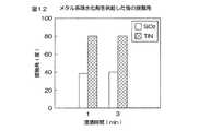
一方、図12に示すように、メタル系疎水化剤に浸漬されたSiO2の試験片に対する純水の接触角は、いずれの浸漬時間においても約40度である。また、図12に示すように、メタル系疎水化剤に浸漬されたTiNの試験片に対する純水の接触角は、いずれの浸漬時間においても約80度である。As shown in FIG. 11, the contact angle of pure water with respect to the test piece of SiO2 immersed in the silicon hydrophobizing agent is 70 degrees or more in any immersion time. Moreover, as shown in FIG. 11, the contact angle of pure water with respect to the TiN test piece immersed in the silicon hydrophobizing agent is 20 degrees or less when the immersion time is 2 minutes or less, and when the immersion time is 3 minutes or more. It is 30 degrees or less.
On the other hand, as shown in FIG. 12, the contact angle of pure water with respect to the
図11および図12に示す測定値から、シリコン系疎水化剤は、シリコンを含む化合物(SiO2)を十分に疎水化できるものの、金属を含む化合物(TiN)を十分に疎水化できないことが分かる。また、メタル系疎水化剤は、金属を含む化合物(TiN)を十分に疎水化できるものの、シリコンを含む化合物(SiO2)を十分に疎水化できないことが分かる。 From the measured values shown in FIGS. 11 and 12, it can be seen that the silicon hydrophobizing agent can sufficiently hydrophobize the silicon-containing compound (SiO 2), but cannot sufficiently hydrophobize the metal-containing compound (TiN). Further, it can be seen that the metal hydrophobizing agent can sufficiently hydrophobize the metal-containing compound (TiN), but cannot sufficiently hydrophobize the silicon-containing compound (SiO2).
一方、図13に示すように、シリコン系疎水化剤およびメタル系疎水化剤に順次浸漬されたSiO2、TiNおよびWの試験片に対する純水の接触角は、それぞれ、約80度、約70度、および約60度である。したがって、シリコン系疎水化剤およびメタル系疎水化剤の両方の疎水化剤を基板Wに供給することにより、シリコンを含む膜および金属膜を含む基板Wを十分に疎水化させることができる。 On the other hand, as shown in FIG. 13, the contact angles of pure water with respect to the
図14は、メタル系疎水化剤に浸漬された金属を含む化合物のリンス処理前後での接触
角を示すグラフである。図14におけるリンス前の接触角は、メタル系疎水化剤の一例である疎水基を有するアミンに浸漬された、金属を含む化合物が、リンスされる前の接触角である。また、図14におけるリンス後の接触角は、疎水基を有するアミンに浸漬された金属を含む化合物が、溶剤A、溶剤B、および純水のいずれかによってリンスされた後の接触角である。溶剤Aおよび溶剤Bは、種類の異なる溶剤である。溶剤Aは、第1処理例および第2処理例において第1溶剤および第2溶剤として用いられる溶剤である。溶剤Bについても同様である。FIG. 14 is a graph showing contact angles before and after rinsing treatment of a compound containing a metal immersed in a metal hydrophobizing agent. The contact angle before rinsing in FIG. 14 is a contact angle before a compound containing a metal immersed in an amine having a hydrophobic group, which is an example of a metal hydrophobizing agent, is rinsed. Further, the contact angle after rinsing in FIG. 14 is a contact angle after a compound containing a metal immersed in an amine having a hydrophobic group is rinsed with any one of the solvent A, the solvent B, and pure water. The solvent A and the solvent B are different types of solvents. The solvent A is a solvent used as the first solvent and the second solvent in the first processing example and the second processing example. The same applies to the solvent B.
図14に示すように、疎水基を有するアミンに浸漬された、金属を含む化合物に対する純水の接触角(リンス前の接触角)は、約90度である。この金属を含む化合物が溶剤Aによって洗われると、接触角が約10度減少する。また、この金属を含む化合物が溶剤Bによって洗われると、接触角が約15度減少する。また、この金属を含む化合物が純水によって洗われると、接触角が約50度減少する。 As shown in FIG. 14, the contact angle of pure water (contact angle before rinsing) with respect to a compound containing a metal immersed in an amine having a hydrophobic group is about 90 degrees. When this metal-containing compound is washed with solvent A, the contact angle is reduced by about 10 degrees. Further, when the compound containing the metal is washed with the solvent B, the contact angle is reduced by about 15 degrees. Further, when the compound containing the metal is washed with pure water, the contact angle is reduced by about 50 degrees.
図14に示す測定値から、疎水基を有するアミンに浸漬された、金属を含む化合物に、純水(OH基を含む液体)を供給すると、溶剤Aおよび溶剤Bを供給した場合に比べて、接触角が大幅に減少することが分かる。したがって、疎水基を有するアミンを基板Wに供給した後に基板Wに純水を供給しない、すなわち、純水が基板Wに接触しない状態に保つことにより、基板Wに対する純水の接触角の減少を抑制することができる。 From the measured values shown in FIG. 14, when pure water (liquid containing OH groups) is supplied to a compound containing a metal immersed in an amine having a hydrophobic group, compared to the case where the solvent A and the solvent B are supplied, It can be seen that the contact angle is greatly reduced. Therefore, the pure water is not supplied to the substrate W after the amine having a hydrophobic group is supplied to the substrate W, that is, the pure water does not contact the substrate W, thereby reducing the contact angle of the pure water with respect to the substrate W. Can be suppressed.
図15は、シリコン系疎水化剤Iおよびシリコン系疎水化剤IIをSiNに順次供給したときのSiNの表面状態の変化を示す模式図である。
前述のように、SiNは、シリコン系疎水化剤Iおよびシリコン系疎水化剤IIの両方の疎水化剤によって疎水化される。シリコン系疎水化剤IIの疎水基は、シリコン系疎水化剤Iの疎水基よりも短い。つまり、シリコン系疎水化剤IIの疎水基の分子量は、シリコン系疎水化剤Iの疎水基の分子量よりも小さい。SiNに対する疎水化剤の反応性は、疎水基が短いほど高い。したがって、シリコン系疎水化剤IIは、シリコン系疎水化剤IよりもSiNに対する反応性が高い。一方、SiNに対する反応性が同じであれば、疎水基が長いほど、SiNに対する純水の接触角を増加させることができる。したがって、シリコン系疎水化剤Iは、シリコン系疎水化剤IIよりもSiNを効率的に疎水化させることができる。FIG. 15 is a schematic diagram showing changes in the surface state of SiN when silicon hydrophobizing agent I and silicon hydrophobizing agent II are sequentially supplied to SiN.
As described above, SiN is hydrophobized by both the silicon hydrophobizing agent I and the silicon hydrophobizing agent II. The hydrophobic group of the silicon hydrophobizing agent II is shorter than the hydrophobic group of the silicon hydrophobizing agent I. That is, the molecular weight of the hydrophobic group of the silicon hydrophobizing agent II is smaller than the molecular weight of the hydrophobic group of the silicon hydrophobizing agent I. The reactivity of the hydrophobizing agent with respect to SiN is higher as the hydrophobic group is shorter. Therefore, the silicon hydrophobizing agent II is more reactive with SiN than the silicon hydrophobizing agent I. On the other hand, if the reactivity with SiN is the same, the longer the hydrophobic group, the greater the contact angle of pure water with SiN. Therefore, the silicon hydrophobizing agent I can hydrophobize SiN more efficiently than the silicon hydrophobizing agent II.
たとえばSiNとSiO2を比較すると、両者はいずれもシリコンを含む化合物であるが、SiNは、SiO2よりも官能基(反応性に富む基)の数が少ない。そのため、シリコン系疎水化剤IIをSiNに供給して、SiNの官能基とシリコン系疎水化剤IIの疎水基を効率的に反応させても、SiNの官能基が少なく、かつシリコン系疎水化剤IIの疎水基が短いため、SiNの表面が十分に疎水化されない。つまり、接触角が十分に増加しない。 For example, when comparing SiN and SiO2, both are compounds containing silicon, but SiN has a smaller number of functional groups (reactive groups) than SiO2. Therefore, even if silicon-based hydrophobizing agent II is supplied to SiN and SiN functional groups and silicon-based hydrophobizing agent II are reacted efficiently, there are few SiN functional groups and silicon-based hydrophobization. Since the hydrophobic group of the agent II is short, the surface of SiN is not sufficiently hydrophobized. That is, the contact angle does not increase sufficiently.
一方、シリコン系疎水化剤Iの疎水基は長いが、シリコン系疎水化剤Iは、シリコン系疎水化剤IIよりもSiNに対する反応性が低い。そのため、シリコン系疎水化剤IをSiNに供給しても、SiNの官能基の一部がシリコン系疎水化剤Iの疎水基とは反応しないため、SiNの疎水性が全体として十分に上がらない。したがって、シリコン系疎水化剤Iおよびシリコン系疎水化剤IIの両方をSiNに供給することにより、シリコン系疎水化剤Iおよびシリコン系疎水化剤IIの両方をSiNに反応させて、SiNを十分に疎水化させることができる。 On the other hand, although the hydrophobic group of the silicon hydrophobizing agent I is long, the silicon hydrophobizing agent I is less reactive to SiN than the silicon hydrophobizing agent II. Therefore, even if the silicon hydrophobizing agent I is supplied to SiN, a part of the functional group of SiN does not react with the hydrophobic group of the silicon hydrophobizing agent I, so that the hydrophobicity of SiN as a whole does not sufficiently increase. . Therefore, by supplying both silicon hydrophobizing agent I and silicon hydrophobizing agent II to SiN, both silicon hydrophobizing agent I and silicon hydrophobizing agent II are reacted with SiN, and SiN is sufficient. Can be hydrophobized.
特に、図15に示すように、シリコン系疎水化剤IをSiNに供給した後に、反応性の高いシリコン系疎水化剤IIをSiNに供給することにより、シリコン系疎水化剤Iの疎水基をSiNの官能基に反応させることができるとともに、シリコン系疎水化剤Iの疎水
基と反応せずに残ったSiNの官能基に、シリコン系疎水化剤IIの疎水基を反応させることができる。これにより、SiNを十分に疎水化させることができる。したがって、SiN膜に対しては、疎水基の長いシリコン系疎水化剤Iを供給した後に、疎水基の短いシリコン系疎水化剤IIを供給することが好ましい。In particular, as shown in FIG. 15, after supplying the silicon hydrophobizing agent I to SiN, the highly reactive silicon hydrophobizing agent II is supplied to SiN, so that the hydrophobic group of the silicon hydrophobizing agent I is removed. While being able to react with the functional group of SiN, the functional group of SiN hydrophobizing agent II can be reacted with the functional group of SiN remaining without reacting with the hydrophobic group of silicon hydrophobizing agent I. Thereby, SiN can fully be hydrophobized. Therefore, it is preferable to supply the silicon hydrophobizing agent II with a short hydrophobic group after supplying the silicon hydrophobizing agent I with a long hydrophobic group to the SiN film.
図16は、パターンPに加わる力について説明するための基板Wの断面図である。
パターンPが形成された基板Wを乾燥させると、基板Wが乾燥していく過程でパターンP同士を引き付ける力が加わって、パターンPが倒壊する場合がある。このときパターンPに加わる力Fは、たとえば、以下の式(1)により表される。
F=(2×σ×Hcosθ)/L・・・(式1)
「σ」は、処理液の表面張力であり、「θ」は、接触角であり、「H」は、パターンPの高さであり、「L」は、パターンP間の間隔である。FIG. 16 is a cross-sectional view of the substrate W for explaining the force applied to the pattern P. FIG.
When the substrate W on which the pattern P is formed is dried, a force that attracts the patterns P is applied in the process of drying the substrate W, and the pattern P may collapse. At this time, the force F applied to the pattern P is expressed by, for example, the following expression (1).
F = (2 × σ × H cos θ) / L (Expression 1)
“Σ” is the surface tension of the treatment liquid, “θ” is the contact angle, “H” is the height of the pattern P, and “L” is the interval between the patterns P.
この式(1)から、処理液の表面張力σが小さいほどパターンPに加わる力Fが減少することが分かる。したがって、処理液の表面張力σを低下させることにより、パターンPに加わる力Fを減少させて、パターンPの倒壊を抑制または防止できる。
また、接触角θが90度に近づくほどパターンPに加わる力Fが減少することが分かる。したがって、基板Wの表面を疎水化させて接触角θを90度に近づけることにより、パターンPの倒壊を抑制または防止することができる。From this equation (1), it can be seen that the force F applied to the pattern P decreases as the surface tension σ of the treatment liquid decreases. Therefore, by reducing the surface tension σ of the processing liquid, the force F applied to the pattern P can be reduced, and the collapse of the pattern P can be suppressed or prevented.
It can also be seen that the force F applied to the pattern P decreases as the contact angle θ approaches 90 degrees. Therefore, the collapse of the pattern P can be suppressed or prevented by making the surface of the substrate W hydrophobic to bring the contact angle θ close to 90 degrees.
一方、基板Wの表面の疎水化が不十分な場合には、パターンPに加わる力Fが十分に減少せず、パターンPの倒壊を十分に抑制することができない。したがって、パターンPの倒壊を十分に抑制するために、基板Wの表面全体を十分に疎水化させることが好ましい。
前述の第1処理例および第2処理例では、疎水化剤によって基板Wが疎水化される(第1疎水化処理および第2疎水化処理)。これにより、基板Wに対する処理液の接触角が90度に近づけられる。したがって、パターンPに加わる力を減少させて、パターンPの倒壊を抑制または防止することができる。On the other hand, when the surface of the substrate W is not sufficiently hydrophobized, the force F applied to the pattern P is not sufficiently reduced, and the collapse of the pattern P cannot be sufficiently suppressed. Therefore, in order to sufficiently suppress the collapse of the pattern P, it is preferable to sufficiently hydrophobize the entire surface of the substrate W.
In the first processing example and the second processing example described above, the substrate W is hydrophobized by the hydrophobizing agent (first hydrophobizing process and second hydrophobizing process). Thereby, the contact angle of the processing liquid with respect to the substrate W is brought close to 90 degrees. Therefore, the force applied to the pattern P can be reduced, and the collapse of the pattern P can be suppressed or prevented.
また、第2処理例では、複数種類の疎水化剤が基板Wに供給される(第1疎水化処理および第2疎水化処理)。したがって、シリコンを含む膜と金属膜を含む積層膜32のパターンPが形成された基板Wを処理する場合に、基板Wの表面全体を十分に疎水化させることができる。さらに、SiN膜などの窒化膜を有する基板Wを処理する場合に、基板Wの疎水性を十分に上昇させることができる。これにより、パターンPの倒壊を抑制または防止することができる。 In the second processing example, plural types of hydrophobizing agents are supplied to the substrate W (first hydrophobizing process and second hydrophobizing process). Therefore, when the substrate W on which the pattern P of the
また、第1処理例および第2処理例では、基板Wが疎水化されてから乾燥するまで(第1疎水化処理が終了してから乾燥処理が終了するまで)、溶剤、または疎水化剤および溶剤が基板Wに供給される。疎水化剤および溶剤は、水を含まない液体である。したがって、第1処理例および第2処理例では、基板Wが疎水化されてから乾燥するまで、基板Wに純水が接触しない状態が保たれる。 In the first processing example and the second processing example, the solvent, the hydrophobizing agent, and the substrate W until the substrate W is hydrophobized and dried (from the end of the first hydrophobizing process to the end of the drying process). A solvent is supplied to the substrate W. The hydrophobizing agent and the solvent are liquids that do not contain water. Therefore, in the first processing example and the second processing example, the pure water is not in contact with the substrate W until the substrate W is dried after being hydrophobized.
図14を参照して説明したように、金属膜を含む基板Wにメタル系疎水化剤の一例である疎水基を有するアミンを供給した後に、当該基板Wに純水を供給すると、基板Wの疎水性が大幅に低下してしまう。したがって、基板Wが疎水化されてから乾燥するまで、基板Wに純水が接触しない状態が保たれることにより、疎水基を有するアミンが基板Wに供給された場合に、基板Wの疎水性が大幅に低下することが防止される。これにより、パターンPの倒壊を抑制または防止することができる。 As described with reference to FIG. 14, when pure water is supplied to the substrate W after supplying an amine having a hydrophobic group, which is an example of a metal hydrophobizing agent, to the substrate W including the metal film, Hydrophobicity is greatly reduced. Accordingly, since the state in which pure water is not in contact with the substrate W is maintained until the substrate W is dried after the hydrophobicity of the substrate W, when the amine having a hydrophobic group is supplied to the substrate W, the hydrophobicity of the substrate W is decreased. Is prevented from significantly decreasing. Thereby, collapse of the pattern P can be suppressed or prevented.
また、基板Wが疎水化されてから乾燥するまで、基板Wに純水が接触しない状態が保たれることにより、ウォーターマークの生成も抑制または防止することができる。
また、第2処理例では、第1疎水化剤によって下層膜が疎水化された後、または第1疎水化剤によって下層膜および上層膜が疎水化された後に、第2疎水化剤によって上層膜が疎水化される。たとえば、上層膜が疎水化された後にさらに疎水化剤を基板Wに供給すると、上層膜が疎水化されているので、疎水化剤が下層膜まで十分に供給されない場合がある。したがって、下層膜が疎水化された後、または下層膜および上層膜が疎水化された後に、上層膜を疎水化する第2疎水化剤を基板Wに供給することにより、上層膜および下層膜を十分に疎水化させることができる。これにより、基板Wを十分に疎水化させることができる。In addition, since the state in which pure water does not contact the substrate W is maintained until the substrate W is dried after being hydrophobized, the generation of watermarks can be suppressed or prevented.
In the second treatment example, after the lower layer film is hydrophobized by the first hydrophobizing agent, or after the lower layer film and the upper layer film are hydrophobized by the first hydrophobizing agent, the upper layer film is formed by the second hydrophobizing agent. Is hydrophobized. For example, if the hydrophobizing agent is further supplied to the substrate W after the upper layer film is hydrophobized, the upper layer film is hydrophobized, and thus the hydrophobizing agent may not be sufficiently supplied to the lower layer film. Therefore, after the lower layer film is hydrophobized, or after the lower layer film and the upper layer film are hydrophobized, a second hydrophobizing agent that hydrophobizes the upper layer film is supplied to the substrate W. It can be sufficiently hydrophobized. Thereby, the substrate W can be sufficiently hydrophobized.
また、第1処理例および第2処理例では、リンス液の一例である純水が基板Wに供給される(水リンス処理)。その後、溶剤が、第1溶剤として基板Wに供給される(第1溶剤リンス処理)。これにより、基板Wに付着している純水が溶剤に置換される。したがって、第1疎水化剤および第2疎水化剤は、純水が除去された状態で基板Wに供給される。そのため、第1疎水化剤および第2疎水化剤が純水に接触することが防止される。よって、水に接触することによって活性が低下する疎水化剤が、第1疎水化剤および第2疎水化剤として用いられている場合に、第1疎水化剤および第2疎水化剤の活性が低下することが防止される。これにより、基板Wを十分に疎水化させることができる。 In the first processing example and the second processing example, pure water, which is an example of a rinsing liquid, is supplied to the substrate W (water rinsing process). Thereafter, the solvent is supplied as the first solvent to the substrate W (first solvent rinsing process). Thereby, the pure water adhering to the substrate W is replaced with the solvent. Therefore, the first hydrophobizing agent and the second hydrophobizing agent are supplied to the substrate W in a state where pure water is removed. This prevents the first hydrophobizing agent and the second hydrophobizing agent from coming into contact with pure water. Therefore, when the hydrophobizing agent whose activity decreases by contact with water is used as the first hydrophobizing agent and the second hydrophobizing agent, the activity of the first hydrophobizing agent and the second hydrophobizing agent is increased. Decrease is prevented. Thereby, the substrate W can be sufficiently hydrophobized.
また、第2処理例では、第1疎水化処理が行われた後であって第2疎水化処理が行われる前に、第1疎水化剤および第2疎水化剤を溶解させることができる溶剤が、第2溶剤として基板Wに供給される(第2溶剤リンス工程)。第1疎水化剤と第2疎水化剤とが容易に混ざり合わない場合、第1疎水化剤が基板Wに付着している状態で第2疎水化剤を基板Wに供給しても、基板Wに付着している第1疎水化剤を容易に第2疎水化剤に置換することができない。そのため、第2疎水化剤が基板Wの表面に十分に接触しない。 In the second treatment example, the solvent capable of dissolving the first hydrophobizing agent and the second hydrophobizing agent after the first hydrophobizing treatment and before the second hydrophobizing treatment is performed. Is supplied to the substrate W as the second solvent (second solvent rinsing step). If the first hydrophobizing agent and the second hydrophobizing agent are not easily mixed, even if the second hydrophobizing agent is supplied to the substrate W while the first hydrophobizing agent is attached to the substrate W, the substrate The first hydrophobizing agent attached to W cannot be easily replaced with the second hydrophobizing agent. For this reason, the second hydrophobizing agent does not sufficiently contact the surface of the substrate W.
一方、溶剤(第2溶剤)は、第1疎水化剤および第2疎水化剤を溶解させることができる。したがって、第1疎水化処理が行われた後に溶剤を基板Wに供給することにより、基板Wに付着している第1疎水化剤を溶剤に置換して、基板Wから第1疎水化剤を除去することができる。そして、第2溶剤リンス処理が行われた後に第2疎水化剤を基板Wに供給することにより、基板Wに付着している溶剤を第2疎水化剤に置換して、基板Wから溶剤を除去することができる。したがって、第1疎水化剤と第2疎水化剤とが容易に混ざり合わない場合であっても、基板Wに付着している第1疎水化剤を第2疎水化剤に置換することができる。これにより、第2疎水化剤を基板Wに反応させて、第2疎水化剤によって基板Wを疎水化することができる。 On the other hand, the solvent (second solvent) can dissolve the first hydrophobizing agent and the second hydrophobizing agent. Therefore, by supplying the solvent to the substrate W after the first hydrophobization treatment, the first hydrophobizing agent adhering to the substrate W is replaced with the solvent, and the first hydrophobizing agent is removed from the substrate W. Can be removed. Then, by supplying the second hydrophobizing agent to the substrate W after the second solvent rinsing process is performed, the solvent adhering to the substrate W is replaced with the second hydrophobizing agent, and the solvent is removed from the substrate W. Can be removed. Therefore, even when the first hydrophobizing agent and the second hydrophobizing agent are not easily mixed, the first hydrophobizing agent attached to the substrate W can be replaced with the second hydrophobizing agent. . Thereby, the second hydrophobizing agent can be reacted with the substrate W, and the substrate W can be hydrophobized by the second hydrophobizing agent.
また、第1処理例および第2処理例では、乾燥前リンス処理において基板Wに溶剤が供給される。そして、基板Wに付着している溶剤が除去され、基板Wが乾燥される。乾燥前リンス処理において基板Wに供給される溶剤は、水より表面張力が小さい。したがって、乾燥前リンス処理において純水が基板Wに供給される場合よりもパターンPの倒壊を抑制または防止することができる。さらに、乾燥前リンス処理において基板Wに供給される溶剤は、水より沸点が低い。したがって、乾燥前リンス処理において純水が基板Wに供給される場合よりも基板Wを速やかに乾燥させることができる。 In the first processing example and the second processing example, the solvent is supplied to the substrate W in the pre-drying rinsing process. Then, the solvent adhering to the substrate W is removed, and the substrate W is dried. The solvent supplied to the substrate W in the pre-drying rinsing process has a surface tension smaller than that of water. Therefore, the collapse of the pattern P can be suppressed or prevented as compared with the case where pure water is supplied to the substrate W in the rinsing process before drying. Furthermore, the solvent supplied to the substrate W in the pre-drying rinsing process has a boiling point lower than that of water. Therefore, the substrate W can be dried more quickly than when pure water is supplied to the substrate W in the rinsing process before drying.
また、第1処理例および第2処理例では、希釈溶剤によって希釈された第1疎水化剤および第2疎水化剤が基板Wに供給される。希釈溶剤は、第1溶剤および第2溶剤として用いられる溶剤を溶解させることができる。したがって、第1疎水化剤および第2疎水化剤が希釈溶剤によって希釈されることにより、第1疎水化剤および第2疎水化剤と第1溶剤および第2溶剤との親和性が高まる。そのため、基板Wに付着している溶剤(第1溶剤および第2溶剤)を第1疎水化剤および第2疎水化剤に容易に置換することができる。 In the first processing example and the second processing example, the first hydrophobizing agent and the second hydrophobizing agent diluted with the diluting solvent are supplied to the substrate W. The dilution solvent can dissolve the solvent used as the first solvent and the second solvent. Therefore, when the first hydrophobizing agent and the second hydrophobizing agent are diluted with the diluting solvent, the affinity between the first hydrophobizing agent and the second hydrophobizing agent and the first solvent and the second solvent is increased. Therefore, the solvent (first solvent and second solvent) adhering to the substrate W can be easily replaced with the first hydrophobizing agent and the second hydrophobizing agent.
また、第1処理例および第2処理例では、集合配管31内で疎水化剤(第1疎水化剤および第2疎水化剤)と希釈溶剤が混合される。すなわち、第1疎水化剤および第2疎水化剤は、基板Wに供給される直前で希釈溶剤によって希釈される。したがって、希釈溶剤によって希釈されることにより活性が次第に低下する疎水化剤が、第1疎水化剤および第2疎水化剤として用いられている場合に、第1疎水化剤および第2疎水化剤の活性が大幅に低下することが防止される。これにより、基板Wを十分に疎水化させることができる。 In the first processing example and the second processing example, the hydrophobizing agent (the first hydrophobizing agent and the second hydrophobizing agent) and the diluting solvent are mixed in the collecting
図17は、本発明の第2実施形態に係る基板処理装置201の概略構成を示す模式図である。図18は、本発明の第2実施形態に係る第1疎水化剤供給ユニット216の概略構成を示す模式図である。この図17および図18において、前述の図1〜図16に示された各部と同等の構成部分については、図1等と同一の参照符号を付してその説明を省略する。 FIG. 17 is a schematic diagram showing a schematic configuration of a
この第2実施形態と前述の第1実施形態との主要な相違点は、図17に示すように、第1疎水化剤の蒸気および第2疎水化剤の蒸気をそれぞれ供給する第1疎水化剤供給ユニット216(疎水化剤供給手段)および第2疎水化剤供給ユニット217(疎水化剤供給手段)が基板処理装置201に備えられていることである。第1疎水化剤供給ユニット216の概略構成と第2疎水化剤供給ユニット217の概略構成は同様であるので、以下では、第1疎水化剤供給ユニット216の概略構成について説明する。 The main difference between the second embodiment and the first embodiment described above is that, as shown in FIG. 17, the first hydrophobization that supplies the vapor of the first hydrophobizing agent and the vapor of the second hydrophobizing agent, respectively. The
図18に示すように、第1疎水化剤供給ユニット216は、第1疎水化剤(液体)が貯留された第1タンク23と、希釈溶剤(液体)が貯留された第2タンク24とを含む。さらに、第1疎水化剤供給ユニット216は、集合配管31に介装されたヒータ233と、バルブ234が介装されたキャリアガス供給配管235とを含む。キャリアガス供給配管235は、集合配管31に接続されている。ヒータ233の温度は、制御装置22(図3参照)によって制御される。また、バルブ234の開閉は、制御装置22によって制御される。バルブ234が開かれると、キャリアガスが集合配管31に供給される。キャリアガスとしては、たとえば、窒素ガスやアルゴンガスなどの不活性ガスが挙げられる。 As shown in FIG. 18, the first hydrophobizing
また、希釈溶剤は、前述の第1実施形態と同様である。第2実施形態では、たとえば、HFEを含む溶剤が希釈溶剤として用いられている。HFEは、水よりも沸点が低い。したがって、この希釈溶剤によって第1疎水化剤を希釈することにより、希釈された第1疎水化剤の沸点を低下させることができる。これにより、希釈された第1疎水化剤を容易に蒸発させることができる。また、HFEは、不燃性である。制御装置22は、希釈された第1疎水化剤が不燃性となるように、第1流量調整バルブ28および第2流量調整バルブ30の開度を制御する。したがって、基板処理装置201の爆発を防止するための対策を施さなくてもよい。 The dilution solvent is the same as that in the first embodiment. In the second embodiment, for example, a solvent containing HFE is used as the dilution solvent. HFE has a lower boiling point than water. Therefore, the boiling point of the diluted first hydrophobizing agent can be lowered by diluting the first hydrophobizing agent with the diluting solvent. Thereby, the diluted 1st hydrophobizing agent can be evaporated easily. HFE is nonflammable. The
制御装置22は、第1バルブ27、第2バルブ29、およびバルブ234を開き、さらに、ヒータ233によって集合配管31を加熱させる。第1バルブ27および第2バルブ29が開かれることにより、第1疎水化剤(液体)および希釈溶剤(液体)が集合配管31に供給される。集合配管31に供給された第1疎水化剤および希釈溶剤は、集合配管31内で混合された後、ヒータ233によって加熱される。これにより、第1疎水化剤および希釈溶剤の混合液が蒸発して、希釈された第1疎水化剤の液体が蒸気に変化する。そして、集合配管31内で生成された第1疎水化剤の蒸気は、キャリアガス供給配管235から集合配管31に供給されたキャリアガスによって中心軸ノズル14に向けて流される。これにより、第1疎水化剤の蒸気が中心軸ノズル14から吐出される。 The
図17に示すように、制御装置22は、遮断板3を処理位置に位置させた状態で、中心軸ノズル14から第1疎水化剤の蒸気および第2疎水化剤の蒸気を吐出させる。中心軸ノ
ズル14から吐出された疎水化剤の蒸気は、遮断板3と基板Wとの間を外方に広がり、遮断板3と基板Wとの間から排出される。これにより、遮断板3と基板Wとの間の空間が疎水化剤の蒸気で満たされる。また、中心軸ノズル14から吐出された疎水化剤の蒸気は、基板Wの上面に沿って外方に流れる。これにより、疎水化剤の蒸気が基板Wの上面全域に供給される。疎水化剤の蒸気が中心軸ノズル14から吐出される間、スピンチャック2によって保持された基板Wは、基板Wの中心を通る鉛直な回転軸線まわりに回転されてもよいし、非回転状態で保持されてもよい。As shown in FIG. 17, the
図19は、本発明の第2実施形態に係る基板処理装置201によって基板Wを処理するときの第3処理例について説明するための工程図である。以下では、図17および図19を参照して、デバイス形成面である表面にパターンPが形成された基板Wを処理するときの処理例について説明する。第3処理例において、第1溶剤リンス処理(S103)までの工程は第1処理例と同様であるので、第1処理例と同一の参照符号を付してその説明を省略する。したがって、以下では、第1溶剤リンス処理が行われた後の工程について説明する。 FIG. 19 is a process diagram for explaining a third processing example when the substrate W is processed by the
第1溶剤リンス処理(S103)が行われた後は、第1疎水化剤(蒸気)を基板Wに供給する第1疎水化処理(疎水化工程、蒸気供給工程)が行われる(S204)。具体的には、制御装置22は、第1疎水化剤供給ユニット216を制御することにより、遮断板3を処理位置に位置させた状態で、中心軸ノズル14から基板Wの上面中央部に向けて第1疎水化剤の蒸気を吐出させる。基板Wに付着している溶剤は、基板Wの上面に沿って外方に流れる第1疎水化剤の蒸気に溶け込みながら基板Wから除去されていく。また、第1疎水化剤の蒸気が基板Wの上面に沿って外方に流れることにより、第1疎水化剤の蒸気が基板Wの上面全域に供給され、第1疎水化剤の蒸気がパターンPの内部に入り込む。これにより、基板Wの上面が疎水化される(第1疎水化処理)。そして、第1疎水化処理が所定時間にわたって行われると、制御装置22は、第1疎水化剤供給ユニット216を制御して、第1疎水化剤の蒸気の吐出を停止させる。 After the first solvent rinsing process (S103) is performed, a first hydrophobizing process (hydrophobizing process, steam supplying process) for supplying the first hydrophobizing agent (vapor) to the substrate W is performed (S204). Specifically, the
次に、基板Wを乾燥させる乾燥処理(乾燥工程、蒸発工程)が行われる(S205)。具体的には、制御装置22は、基板Wの上面に付着している第1疎水化剤の液滴を蒸発させることにより、基板Wを乾燥させる(乾燥処理)。制御装置22は、スピンチャック2によって基板Wを回転させることにより、基板Wの回転によって生じる気流によって第1疎水化剤の液滴を蒸発させてもよいし、基板Wを静止させながら第1疎水化剤の液滴を自然に蒸発させてもよい。また、制御装置22は、搬送ロボットによって基板Wを搬送させながら第1疎水化剤の液滴を蒸発させてもよい。 Next, a drying process (drying process, evaporation process) for drying the substrate W is performed (S205). Specifically, the
図20は、本発明の第2実施形態に係る基板処理装置201によって基板Wを処理するときの第4処理例について説明するための工程図である。以下では、図17および図20を参照して、デバイス形成面である表面にパターンPが形成された基板Wを処理するときの処理例について説明する。第4処理例では、2種類の疎水化剤の蒸気が基板Wに供給される。第4処理例において、第1疎水化処理(S204)までの工程は第3処理例と同様であるので、第3処理例と同一の参照符号を付してその説明を省略する。したがって、以下では、第1疎水化処理が行われた後の工程について説明する。 FIG. 20 is a process diagram for explaining a fourth processing example when the substrate W is processed by the
第1疎水化処理(S204)が行われた後は、溶剤を基板Wに供給する第2溶剤リンス処理(第2溶剤リンス工程)が行われる(S206)。具体的には、制御装置22は、溶剤バルブ18を開いて、遮断板3を処理位置に位置させ、さらに、スピンチャック2によって基板Wを回転させながら、中心軸ノズル14から基板Wの上面中央部に向けて溶剤を吐出させる。これにより、中心軸ノズル14から吐出された溶剤が、第2溶剤として基板Wの上面全域に供給される。前述のように、溶剤は、疎水化剤を溶解させることができる
液体であるから、基板Wの上面全域に溶剤が供給されることにより、基板Wに付着している第1疎水化剤の液滴が、溶剤に置換される(第2溶剤リンス処理)。そして、第2溶剤リンス処理が所定時間にわたって行われると、制御装置22は、溶剤バルブ18を閉じて溶剤の吐出を停止させる。After the first hydrophobizing process (S204) is performed, a second solvent rinsing process (second solvent rinsing process) for supplying a solvent to the substrate W is performed (S206). Specifically, the
第2溶剤リンス工程(S206)が行われた後は、第2疎水化剤(蒸気)を基板Wに供給する第2疎水化処理(疎水化工程、蒸気供給工程)が行われる(S207)。具体的には、制御装置22は、第2疎水化剤供給ユニット217を制御することにより、遮断板3を処理位置に位置させた状態で、中心軸ノズル14から基板Wの上面中央部に向けて第2疎水化剤の蒸気を吐出させる。第2疎水化剤の蒸気が基板Wの上面に沿って外方に流れることにより、第2疎水化剤の蒸気が基板Wの上面全域に供給され、第2疎水化剤の蒸気がパターンPの内部に入り込む。これにより、基板Wの上面が疎水化される(第2疎水化処理)。そして、第2疎水化処理が所定時間にわたって行われると、制御装置22は、第2疎水化剤供給ユニット217を制御して、第2疎水化剤の蒸気の吐出を停止させる。 After the second solvent rinsing step (S206) is performed, a second hydrophobizing process (hydrophobizing step, vapor supplying step) for supplying the second hydrophobizing agent (vapor) to the substrate W is performed (S207). Specifically, the
次に、基板Wを乾燥させる乾燥処理(乾燥工程、蒸発工程)が行われる(S208)。具体的には、制御装置22は、基板Wの上面に付着している第2疎水化剤の液滴を蒸発させることにより、基板Wを乾燥させる(乾燥処理)。制御装置22は、スピンチャック2によって基板Wを回転させることにより、基板Wの回転によって生じる気流によって第2疎水化剤の液滴を蒸発させてもよいし、基板Wを静止させながら第2疎水化剤の液滴を自然に蒸発させてもよい。また、制御装置22は、搬送ロボットに搬送させながら第2疎水化剤の液滴を蒸発させてもよい。 Next, a drying process (drying process, evaporation process) for drying the substrate W is performed (S208). Specifically, the
第3処理例は、前述の第1処理例に対応しており、第4処理例は、前述の第2処理例に対応している。すなわち、基板処理装置201によって処理される基板Wは、たとえば、積層膜32のパターンPが形成された基板W(図7参照)である。第1膜32a、第2膜32b、および第3膜32cが、それぞれ、シリコンを含む膜、シリコンを含む膜、金属膜である場合(図8参照)、第3処理例では、たとえば、シリコン系疎水化剤またはメタル系疎水化剤が第1疎水化剤として用いられる。また、第1膜32a、第2膜32b、および第3膜32cが、それぞれ、シリコンを含む膜、シリコンを含む膜、金属膜である場合(図8参照)、第4処理例では、たとえば、メタル系疎水化剤が第1疎水化剤として用いられ、シリコン系疎水化剤が第2疎水化剤として用いられる。第1膜32a、第2膜32b、および第3膜32cのその他の組み合わせについても同様である。 The third processing example corresponds to the first processing example described above, and the fourth processing example corresponds to the second processing example described above. That is, the substrate W processed by the
以上のように第2実施形態では、第3処理例および第4処理例のいずれの処理例においても、疎水化剤の蒸気が基板Wに供給される(第1疎水化処理および第2疎水化処理)。基板Wに供給された疎水化剤の蒸気の一部は液滴に変化して、基板Wに付着する。しかし、この疎水化剤の液滴は短時間で蒸発して、基板Wから除去される。そのため、第1処理例および第2処理例のように、溶剤によって疎水化剤を洗い流さなくてもよい。すなわち、乾燥前リンス処理を行わなくてもよい。これにより、基板Wの処理時間を短縮することができる。 As described above, in the second embodiment, the hydrophobizing agent vapor is supplied to the substrate W in both the third processing example and the fourth processing example (the first hydrophobizing process and the second hydrophobizing process). processing). A part of the hydrophobizing agent vapor supplied to the substrate W changes into droplets and adheres to the substrate W. However, the hydrophobizing agent droplets evaporate in a short time and are removed from the substrate W. Therefore, it is not necessary to wash away the hydrophobizing agent with a solvent as in the first processing example and the second processing example. That is, the pre-drying rinsing process may not be performed. Thereby, the processing time of the substrate W can be shortened.
また、第4処理例では、第1疎水化処理の後に、第2疎水化処理に先立って、第2溶剤リンス処理が行われる。第1疎水化処理が終わった段階で、第1疎水化剤の液滴が基板Wから蒸発して、基板Wが乾燥すると、基板Wの疎水性が十分に低下していないため、パターンPが倒壊する恐れがある。したがって、第1疎水化剤の液滴が蒸発して除去される前に、基板Wに溶剤を供給する第2溶剤リンス処理を行うことにより、基板Wが乾燥することを防止する。その後、第2疎水化剤の蒸気が供給されることにより、基板Wに付着している溶剤が第2疎水化剤と置換され、第2疎水化処理が行われる。 In the fourth treatment example, after the first hydrophobic treatment, the second solvent rinse treatment is performed prior to the second hydrophobic treatment. When the first hydrophobizing treatment is finished, when the droplets of the first hydrophobizing agent evaporate from the substrate W and the substrate W is dried, the hydrophobicity of the substrate W is not sufficiently lowered. There is a risk of collapse. Therefore, the substrate W is prevented from drying by performing the second solvent rinsing process for supplying the solvent to the substrate W before the droplets of the first hydrophobizing agent are removed by evaporation. Thereafter, the vapor of the second hydrophobizing agent is supplied, whereby the solvent adhering to the substrate W is replaced with the second hydrophobizing agent, and the second hydrophobizing treatment is performed.
また、第3処理例および第4処理例では、基板Wが疎水化されてから乾燥するまで(第1疎水化処理が終了してから乾燥処理が終了するまで)、基板Wに純水が接触しない状態が保たれる。したがって、金属膜を含む基板Wにメタル系疎水化剤の一例である疎水基を有するアミンを供給した場合に、基板Wの疎水性が大幅に低下することが防止される。これにより、パターンPの倒壊を抑制または防止することができる。 In the third processing example and the fourth processing example, pure water is in contact with the substrate W until the substrate W is hydrophobized and then dried (from the end of the first hydrophobizing process to the end of the drying process). The state which does not do is kept. Therefore, when an amine having a hydrophobic group, which is an example of a metal hydrophobizing agent, is supplied to the substrate W including the metal film, the hydrophobicity of the substrate W is prevented from being significantly reduced. Thereby, collapse of the pattern P can be suppressed or prevented.
また、基板Wが疎水化されてから乾燥するまで、基板Wに純水が接触しない状態が保たれることにより、ウォーターマークの生成も抑制または防止することができる。
この発明の実施の形態の説明は以上であるが、この発明は、前述の実施形態の内容に限定されるものではなく、請求項記載の範囲内において種々の変更が可能である。たとえば、前述の第1処理例〜第4処理例では、第1溶剤リンス処理、第2溶剤リンス処理、乾燥前リンス処理において、溶剤を基板Wに供給する場合について説明したが、基板Wに付着している液に十分に溶け込むのであれば、溶剤の蒸気を供給するようにしてもよい。In addition, since the state in which pure water does not contact the substrate W is maintained until the substrate W is dried after being hydrophobized, the generation of watermarks can be suppressed or prevented.
Although the embodiments of the present invention have been described above, the present invention is not limited to the contents of the above-described embodiments, and various modifications can be made within the scope of the claims. For example, in the first to fourth processing examples described above, the case where the solvent is supplied to the substrate W in the first solvent rinsing process, the second solvent rinsing process, and the pre-drying rinsing process has been described. The solvent vapor may be supplied if it is sufficiently dissolved in the liquid.
また、前述の第1処理例〜第4処理例では、基板Wに溶剤を供給する第1溶剤リンス処理が行われた後に、第1疎水化剤を基板Wに供給する第1疎水化処理が行われる場合について説明した。しかし、純水が第1疎水化剤に溶解し、かつ第1疎水化剤が純水に接触しても活性が低下しない場合には、基板Wに純水を供給する水リンス処理が行われた後に、第1溶剤リンス処理を行わずに、第1疎水化処理を行ってもよい。 In the first to fourth processing examples, the first hydrophobizing process for supplying the first hydrophobizing agent to the substrate W after the first solvent rinsing process for supplying the solvent to the substrate W is performed. The case where it is performed was explained. However, when the pure water is dissolved in the first hydrophobizing agent and the activity does not decrease even when the first hydrophobizing agent contacts the pure water, a water rinsing process for supplying pure water to the substrate W is performed. After that, the first hydrophobizing treatment may be performed without performing the first solvent rinsing treatment.
また、前述の第2処理例では、第1疎水化処理が行われた後であって第2疎水化処理が行われる前に、溶剤を基板Wに供給する第2溶剤リンス処理が行われる場合について説明した。しかし、第1疎水化剤および第2疎水化剤が容易に混ざり合う場合には、第2溶剤リンス処理を行わずに、第1疎水化剤を基板Wに供給する第1疎水化処理が行われた後に、第2疎水化剤を基板Wに供給する第2疎水化処理が行われてもよい。 In the second processing example described above, the second solvent rinsing process for supplying the solvent to the substrate W is performed after the first hydrophobizing process and before the second hydrophobizing process. Explained. However, when the first hydrophobizing agent and the second hydrophobizing agent are easily mixed, the first hydrophobizing process for supplying the first hydrophobizing agent to the substrate W is performed without performing the second solvent rinsing process. After the breakage, a second hydrophobizing process for supplying the second hydrophobizing agent to the substrate W may be performed.
また、前述の第1処理例〜第4処理例では、第1疎水化処理および第2疎水化処理において、一定の濃度に希釈された疎水化剤の液体または蒸気が基板Wに供給される場合について説明した。しかし、制御装置22が流量調整バルブ28、30(図4および図18参照)の開度を制御することにより、疎水化剤の濃度が連続的にまたは段階的に増加されてもよい。この場合、第1疎水化処理および第2疎水化処理において基板Wに付着している溶剤を疎水化剤にスムーズに置換できるから、溶剤を基板Wから除去する時間を短縮することができる。 In the first to fourth processing examples, the liquid or vapor of the hydrophobizing agent diluted to a certain concentration is supplied to the substrate W in the first hydrophobizing process and the second hydrophobizing process. Explained. However, the concentration of the hydrophobizing agent may be increased continuously or stepwise by the
また、前述の第1処理例〜第4処理例では、薬液ノズル10および中心軸ノズル14から処理液を吐出させながら基板Wを処理する場合について説明した。しかし、基板W上に処理液の液膜を保持させることにより基板Wを処理してもよい。具体的には、スピンチャ
ック2によって10〜30rpm程度の低回転速度で基板Wを回転させながら、または基板Wの回転を停止させながら、薬液ノズル10または中心軸ノズル14から処理液を吐出させる。そして、基板Wの上面を覆う処理液の液膜が形成された後に処理液の吐出を停止させる。その後、処理液の吐出を停止させた状態で、基板Wを前述の低回転速度で回転させながら、または基板Wの回転を停止させながら、処理液の液膜によって基板Wを処理する。In the first to fourth processing examples, the case where the substrate W is processed while discharging the processing liquid from the chemical
また、前述の第1処理例〜第4処理例では、水リンス処理において、リンス液の一例である純水が基板に供給される場合について説明した。しかし、純水に限らず、純水以外のリンス液が基板に供給されてもよい。
また、前述の第1処理例〜第4処理例では、積層膜32のパターンPが形成された基板Wが処理される場合について説明した。しかし、単膜のパターンPが形成された基板Wが処理されてもよい。たとえば、SiN膜のみのパターンPが形成された基板Wに対して、前述のように疎水基の長いシリコン系疎水化剤および疎水基の短いシリコン系疎水化剤を第2処理例もしくは第4処理例で処理されることにより、SiN膜を十分に疎水化することができる。In the first to fourth processing examples, the case where pure water, which is an example of the rinsing liquid, is supplied to the substrate in the water rinsing process has been described. However, not only pure water, but also a rinsing liquid other than pure water may be supplied to the substrate.
In the first processing example to the fourth processing example, the case where the substrate W on which the pattern P of the
また、第2処理例および第4処理例では、第1疎水化剤および第2疎水化剤を用いて疎水化処理を2回行っているが、さらに第3疎水化剤を用いて疎水化処理を3回行ってもよい。たとえば、図10に示す膜の組合せの場合、第1疎水化剤としてメタル系疎水化剤を用いることにより、金属膜の疎水化処理を行い、第2疎水化剤として疎水基が長いシリコン系疎水化剤Iを用いることにより、SiN膜の疎水化処理を行い、第3疎水化剤として疎水基が短いシリコン系疎水化剤IIを用いることにより、SiN膜のさらなる疎水化処理を行うようにしてもよい。 In the second treatment example and the fourth treatment example, the hydrophobizing treatment is performed twice using the first hydrophobizing agent and the second hydrophobizing agent, but the hydrophobizing treatment is further performed using the third hydrophobizing agent. May be performed three times. For example, in the case of the combination of films shown in FIG. 10, a metal-based hydrophobizing agent is used as the first hydrophobizing agent to hydrophobize the metal film, and the second hydrophobizing agent is a silicon-based hydrophobic The hydrophobizing treatment of the SiN film is performed by using the agent I, and the hydrophobizing treatment of the SiN film is performed by using the silicon hydrophobizing agent II having a short hydrophobic group as the third hydrophobizing agent. Also good.
また、前述の第1処理例〜第4処理例では、基板Wが1枚ずつ処理される場合について説明した。しかし、第1処理例〜第4処理例において、複数枚の基板Wが一括して処理されてもよい。
その他、特許請求の範囲に記載された事項の範囲で種々の設計変更を施すことが可能である。In the first to fourth processing examples, the case where the substrates W are processed one by one has been described. However, in the first processing example to the fourth processing example, a plurality of substrates W may be processed at once.
In addition, various design changes can be made within the scope of matters described in the claims.
1 基板処理装置
2 スピンチャック(基板保持手段、基板乾燥手段)
16 第1疎水化剤供給ユニット(疎水化剤供給手段)
17 第2疎水化剤供給ユニット(疎水化剤供給手段)
18 溶剤バルブ(溶剤供給手段)
22 制御装置(制御手段)
32 積層膜
201 基板処理装置
216 第1疎水化剤供給ユニット(疎水化剤供給手段)
217 第2疎水化剤供給ユニット(疎水化剤供給手段)
P パターン
S102 水リンス工程
S103 第1溶剤リンス工程
S104 疎水化工程
S105 乾燥前リンス工程
S106 乾燥工程
S107 第2溶剤リンス工程
S108 疎水化工程
S109 乾燥前リンス工程
S110 乾燥工程
S204 疎水化工程、蒸気供給工程
S205 乾燥工程、蒸発工程
S207 疎水化工程、蒸気供給工程
S208 乾燥工程、蒸発工程
W 基板1.
16 First hydrophobizing agent supply unit (hydrophobizing agent supplying means)
17 Second hydrophobizing agent supply unit (hydrophobizing agent supplying means)
18 Solvent valve (solvent supply means)
22 Control device (control means)
32
217 Second hydrophobizing agent supply unit (hydrophobizing agent supplying means)
P pattern S102 water rinsing step S103 first solvent rinsing step S104 hydrophobizing step S105 pre-drying rinsing step S106 drying step S107 second solvent rinsing step S108 hydrophobizing step S109 pre-drying rinsing step S110 drying step S204 hydrophobizing step, steam supply step S205 Drying process, evaporation process S207 Hydrophobization process, steam supply process S208 Drying process, evaporation process W Substrate
Claims (7)
Translated fromJapanese前記疎水化工程が行われた後に前記基板を乾燥させる乾燥工程と、
前記疎水化工程が終了してから前記乾燥工程が終了するまで、前記基板を水が接触しない状態に保つ工程とを含む、基板処理方法。A hydrophobizing step of supplying a hydrophobizing agent to the substrate to hydrophobize the surface of the substrate;
A drying step of drying the substrate after the hydrophobization step is performed;
And a step of keeping the substrate in contact with water from the end of the hydrophobizing step to the end of the drying step.
前記疎水化工程が行われた後であって前記乾燥工程が行われる前に、前記疎水化剤を溶解させることができ、かつ水より表面張力が小さい溶剤を前記基板に供給する乾燥前リンス工程をさらに含む、請求項1または2に記載の基板処理方法。The hydrophobizing step includes a step of supplying a liquid of the hydrophobizing agent to the substrate,
A pre-drying rinsing step for supplying the substrate with a solvent capable of dissolving the hydrophobizing agent and having a smaller surface tension than water after the hydrophobizing step and before the drying step The substrate processing method according to claim 1, further comprising:
前記乾燥工程は、前記基板に付着している前記疎水化剤を蒸発させる蒸発工程を含む、請求項1または2に記載の基板処理方法。The hydrophobizing step includes a vapor supplying step of supplying the hydrophobizing agent vapor to the substrate,
The substrate processing method according to claim 1, wherein the drying step includes an evaporation step of evaporating the hydrophobizing agent adhering to the substrate.
前記基板保持手段に保持された基板に疎水化剤を供給する疎水化剤供給手段と、
基板を乾燥させる基板乾燥手段と、
前記疎水化剤供給手段を制御することにより、疎水化剤を前記基板保持手段に保持された基板に供給して前記基板の表面を疎水化させる疎水化工程を行い、前記基板乾燥手段を制御することにより、前記疎水化工程が行われた後に前記基板を乾燥させる乾燥工程を行い、前記疎水化工程が終了してから前記乾燥工程が終了するまで、前記基板を水が接触しない状態に保つ工程を行う制御手段とを備える、基板処理装置。Substrate holding means for holding the substrate;
A hydrophobizing agent supply means for supplying a hydrophobizing agent to the substrate held by the substrate holding means;
A substrate drying means for drying the substrate;
By controlling the hydrophobizing agent supply means, a hydrophobizing step is performed in which the hydrophobizing agent is supplied to the substrate held by the substrate holding means to hydrophobize the surface of the substrate, and the substrate drying means is controlled. A step of drying the substrate after the hydrophobizing step is performed, and a step of keeping the substrate in contact with water from the end of the hydrophobizing step to the end of the drying step. A substrate processing apparatus.
前記疎水化剤を溶解させることができ、かつ水より表面張力が小さい溶剤を前記基板保持手段に保持された基板に供給する溶剤供給手段をさらに含み、
前記制御手段は、前記疎水化剤供給手段を制御することにより、前記基板保持手段に保持された基板に前記疎水化剤の液体を供給する工程を含む前記疎水化工程を行い、前記溶剤供給手段を制御することにより、前記疎水化工程が行われた後であって前記乾燥工程が行われる前に、前記基板保持手段に保持された基板に前記溶剤を供給する乾燥前リンス工程を行う、請求項5記載の基板処理装置。The hydrophobizing agent supplying means includes means for supplying a liquid of the hydrophobizing agent to a substrate held by the substrate holding means,
A solvent supply unit that can dissolve the hydrophobizing agent and supply a solvent having a surface tension smaller than that of water to the substrate held by the substrate holding unit;
The control means performs the hydrophobization step including supplying the liquid of the hydrophobizing agent to the substrate held by the substrate holding means by controlling the hydrophobizing agent supply means, and the solvent supply means By performing a pre-drying rinsing step of supplying the solvent to the substrate held by the substrate holding means after the hydrophobizing step and before the drying step. Item 6. The substrate processing apparatus according to Item 5.
前記制御手段は、前記疎水化剤供給手段を制御することにより、前記基板保持手段に保持された基板に前記疎水化剤の蒸気を供給する蒸気供給工程を含む前記疎水化工程を行い、前記基板乾燥手段を制御することにより、前記基板保持手段に保持された基板に付着している前記疎水化剤を蒸発させる蒸発工程を含む前記乾燥工程を行う、請求項5記載の基板処理装置。The hydrophobizing agent supply means includes means for supplying vapor of the hydrophobizing agent to a substrate held by the substrate holding means,
The control means performs the hydrophobization step including a vapor supply step of supplying the vapor of the hydrophobizing agent to the substrate held by the substrate holding means by controlling the hydrophobizing agent supply means, and the substrate The substrate processing apparatus according to claim 5, wherein the drying step includes an evaporation step of evaporating the hydrophobizing agent attached to the substrate held by the substrate holding unit by controlling the drying unit.
Priority Applications (8)
| Application Number | Priority Date | Filing Date | Title |
|---|---|---|---|
| JP2011099529AJP5248652B2 (en) | 2011-04-27 | 2011-04-27 | Substrate processing method and substrate processing apparatus |
| KR1020110081213AKR101266620B1 (en) | 2010-08-20 | 2011-08-16 | Substrate processing method and substrate processing apparatus |
| US13/212,716US8821974B2 (en) | 2010-08-20 | 2011-08-18 | Substrate processing method |
| TW100129708ATWI459461B (en) | 2010-08-20 | 2011-08-19 | Substrate processing method and substrate processing apparatus |
| CN201510065454.1ACN104616976B (en) | 2010-08-20 | 2011-08-19 | Substrate processing method using same |
| CN201110242631.0ACN102376540B (en) | 2010-08-20 | 2011-08-19 | Substrate processing method and substrate processing apparatus |
| US14/300,354US9005703B2 (en) | 2010-08-20 | 2014-06-10 | Substrate processing method |
| US14/639,423US9455134B2 (en) | 2010-08-20 | 2015-03-05 | Substrate processing method |
Applications Claiming Priority (1)
| Application Number | Priority Date | Filing Date | Title |
|---|---|---|---|
| JP2011099529AJP5248652B2 (en) | 2011-04-27 | 2011-04-27 | Substrate processing method and substrate processing apparatus |
Related Parent Applications (1)
| Application Number | Title | Priority Date | Filing Date |
|---|---|---|---|
| JP2010185415ADivisionJP5662081B2 (en) | 2010-08-20 | 2010-08-20 | Substrate processing method and substrate processing apparatus |
Publications (2)
| Publication Number | Publication Date |
|---|---|
| JP2012044144Atrue JP2012044144A (en) | 2012-03-01 |
| JP5248652B2 JP5248652B2 (en) | 2013-07-31 |
Family
ID=45900062
Family Applications (1)
| Application Number | Title | Priority Date | Filing Date |
|---|---|---|---|
| JP2011099529AActiveJP5248652B2 (en) | 2010-08-20 | 2011-04-27 | Substrate processing method and substrate processing apparatus |
Country Status (1)
| Country | Link |
|---|---|
| JP (1) | JP5248652B2 (en) |
Cited By (7)
| Publication number | Priority date | Publication date | Assignee | Title |
|---|---|---|---|---|
| WO2013132881A1 (en)* | 2012-03-06 | 2013-09-12 | 東京エレクトロン株式会社 | Liquid processing method, liquid processing device, and storage medium |
| KR20150105589A (en)* | 2014-03-08 | 2015-09-17 | 주식회사 제우스 | method of drying substrate |
| JP2015211207A (en)* | 2014-04-30 | 2015-11-24 | 東京エレクトロン株式会社 | Substrate liquid processing apparatus and substrate liquid processing method |
| JP2016195207A (en)* | 2015-04-01 | 2016-11-17 | 株式会社東芝 | Substrate processing apparatus and substrate processing method |
| KR20170095757A (en) | 2016-02-15 | 2017-08-23 | 도쿄엘렉트론가부시키가이샤 | Liquid processing method, substrate processing apparatus, and storage medium |
| US10121648B2 (en) | 2014-09-30 | 2018-11-06 | SCREEN Holdings Co., Ltd. | Substrate processing method and substrate processing apparatus |
| US10867814B2 (en) | 2016-02-15 | 2020-12-15 | Tokyo Electron Limited | Liquid processing method, substrate processing apparatus, and storage medium |
Citations (4)
| Publication number | Priority date | Publication date | Assignee | Title |
|---|---|---|---|---|
| JP2002050600A (en)* | 2000-05-15 | 2002-02-15 | Tokyo Electron Ltd | Substrate-processing method and substrate processor |
| JP2010129932A (en)* | 2008-11-28 | 2010-06-10 | Tokyo Ohka Kogyo Co Ltd | Surface treatment method and liquid |
| JP2011124410A (en)* | 2009-12-11 | 2011-06-23 | Toshiba Corp | Apparatus and method for processing surface of semiconductor substrate |
| JP2011135002A (en)* | 2009-12-25 | 2011-07-07 | Tokyo Electron Ltd | Substrate processing method, storage medium recording program for executing substrate processing method, and substrate processing apparatus |
- 2011
- 2011-04-27JPJP2011099529Apatent/JP5248652B2/enactiveActive
Patent Citations (4)
| Publication number | Priority date | Publication date | Assignee | Title |
|---|---|---|---|---|
| JP2002050600A (en)* | 2000-05-15 | 2002-02-15 | Tokyo Electron Ltd | Substrate-processing method and substrate processor |
| JP2010129932A (en)* | 2008-11-28 | 2010-06-10 | Tokyo Ohka Kogyo Co Ltd | Surface treatment method and liquid |
| JP2011124410A (en)* | 2009-12-11 | 2011-06-23 | Toshiba Corp | Apparatus and method for processing surface of semiconductor substrate |
| JP2011135002A (en)* | 2009-12-25 | 2011-07-07 | Tokyo Electron Ltd | Substrate processing method, storage medium recording program for executing substrate processing method, and substrate processing apparatus |
Cited By (11)
| Publication number | Priority date | Publication date | Assignee | Title |
|---|---|---|---|---|
| WO2013132881A1 (en)* | 2012-03-06 | 2013-09-12 | 東京エレクトロン株式会社 | Liquid processing method, liquid processing device, and storage medium |
| US8956465B2 (en) | 2012-03-06 | 2015-02-17 | Tokyo Electron Limited | Liquid processing method, liquid processing device, and storage medium |
| KR101497288B1 (en) | 2012-03-06 | 2015-02-27 | 도쿄엘렉트론가부시키가이샤 | Liquid processing method, liquid processing device, and storage medium |
| KR20150105589A (en)* | 2014-03-08 | 2015-09-17 | 주식회사 제우스 | method of drying substrate |
| KR101941214B1 (en)* | 2014-03-08 | 2019-01-23 | 주식회사 제우스 | method of drying substrate |
| JP2015211207A (en)* | 2014-04-30 | 2015-11-24 | 東京エレクトロン株式会社 | Substrate liquid processing apparatus and substrate liquid processing method |
| US10121648B2 (en) | 2014-09-30 | 2018-11-06 | SCREEN Holdings Co., Ltd. | Substrate processing method and substrate processing apparatus |
| JP2016195207A (en)* | 2015-04-01 | 2016-11-17 | 株式会社東芝 | Substrate processing apparatus and substrate processing method |
| US10290491B2 (en) | 2015-04-01 | 2019-05-14 | Toshiba Memory Corporation | Substrate treatment apparatus and substrate treatment method |
| KR20170095757A (en) | 2016-02-15 | 2017-08-23 | 도쿄엘렉트론가부시키가이샤 | Liquid processing method, substrate processing apparatus, and storage medium |
| US10867814B2 (en) | 2016-02-15 | 2020-12-15 | Tokyo Electron Limited | Liquid processing method, substrate processing apparatus, and storage medium |
Also Published As
| Publication number | Publication date |
|---|---|
| JP5248652B2 (en) | 2013-07-31 |
Similar Documents
| Publication | Publication Date | Title |
|---|---|---|
| JP5662081B2 (en) | Substrate processing method and substrate processing apparatus | |
| KR101266620B1 (en) | Substrate processing method and substrate processing apparatus | |
| KR102068443B1 (en) | Substrate processing method and substrate processing apparatus | |
| JP5248652B2 (en) | Substrate processing method and substrate processing apparatus | |
| KR102094562B1 (en) | Substrate processing apparatus | |
| JP5771035B2 (en) | Substrate processing method and substrate processing apparatus | |
| CN109545654B (en) | Substrate processing method and substrate processing device | |
| KR102544412B1 (en) | Substrate processing method and substrate processing apparatus | |
| TWI669769B (en) | Method of processing substrate and substrate processing apparatus | |
| KR20120084651A (en) | Susbtrate treatment method and substrate treatment apparatus | |
| US20130014785A1 (en) | Substrate processing method and substrate processing apparatus | |
| JP6948840B2 (en) | Board processing method and board processing equipment | |
| US10032658B2 (en) | Manufacturing method of semiconductor device and semiconductor manufacturing apparatus | |
| JP6901944B2 (en) | Board processing method and board processing equipment | |
| JP5674851B2 (en) | Substrate processing method and substrate processing apparatus | |
| TWI837643B (en) | Substrate processing method, substrate processing apparatus, and dry processing solution | |
| JP6310583B2 (en) | Substrate processing method and substrate processing apparatus | |
| JP6118309B2 (en) | Substrate processing method | |
| JP2023076165A (en) | Substrate processing method |
Legal Events
| Date | Code | Title | Description |
|---|---|---|---|
| A977 | Report on retrieval | Free format text:JAPANESE INTERMEDIATE CODE: A971007 Effective date:20120816 | |
| A131 | Notification of reasons for refusal | Free format text:JAPANESE INTERMEDIATE CODE: A131 Effective date:20120823 | |
| A521 | Request for written amendment filed | Free format text:JAPANESE INTERMEDIATE CODE: A523 Effective date:20121017 | |
| TRDD | Decision of grant or rejection written | ||
| A01 | Written decision to grant a patent or to grant a registration (utility model) | Free format text:JAPANESE INTERMEDIATE CODE: A01 Effective date:20130314 | |
| A61 | First payment of annual fees (during grant procedure) | Free format text:JAPANESE INTERMEDIATE CODE: A61 Effective date:20130410 | |
| R150 | Certificate of patent or registration of utility model | Ref document number:5248652 Country of ref document:JP Free format text:JAPANESE INTERMEDIATE CODE: R150 | |
| FPAY | Renewal fee payment (event date is renewal date of database) | Free format text:PAYMENT UNTIL: 20160419 Year of fee payment:3 | |
| S533 | Written request for registration of change of name | Free format text:JAPANESE INTERMEDIATE CODE: R313533 | |
| R350 | Written notification of registration of transfer | Free format text:JAPANESE INTERMEDIATE CODE: R350 | |
| R250 | Receipt of annual fees | Free format text:JAPANESE INTERMEDIATE CODE: R250 | |
| R250 | Receipt of annual fees | Free format text:JAPANESE INTERMEDIATE CODE: R250 | |
| R250 | Receipt of annual fees | Free format text:JAPANESE INTERMEDIATE CODE: R250 | |
| R250 | Receipt of annual fees | Free format text:JAPANESE INTERMEDIATE CODE: R250 | |
| R250 | Receipt of annual fees | Free format text:JAPANESE INTERMEDIATE CODE: R250 | |
| R250 | Receipt of annual fees | Free format text:JAPANESE INTERMEDIATE CODE: R250 | |
| R250 | Receipt of annual fees | Free format text:JAPANESE INTERMEDIATE CODE: R250 | |
| R250 | Receipt of annual fees | Free format text:JAPANESE INTERMEDIATE CODE: R250 | |
| R250 | Receipt of annual fees | Free format text:JAPANESE INTERMEDIATE CODE: R250 | |
| R250 | Receipt of annual fees | Free format text:JAPANESE INTERMEDIATE CODE: R250 |