JP2012040895A - Gear transmission system for bicycles - Google Patents
Gear transmission system for bicyclesDownload PDFInfo
- Publication number
- JP2012040895A JP2012040895AJP2010181296AJP2010181296AJP2012040895AJP 2012040895 AJP2012040895 AJP 2012040895AJP 2010181296 AJP2010181296 AJP 2010181296AJP 2010181296 AJP2010181296 AJP 2010181296AJP 2012040895 AJP2012040895 AJP 2012040895A
- Authority
- JP
- Japan
- Prior art keywords
- derailleur
- gear
- control device
- transmission system
- sprocket
- Prior art date
- Legal status (The legal status is an assumption and is not a legal conclusion. Google has not performed a legal analysis and makes no representation as to the accuracy of the status listed.)
- Pending
Links
- 230000005540biological transmissionEffects0.000titleclaimsabstractdescription21
- 238000005259measurementMethods0.000claimsdescription13
- 238000000034methodMethods0.000claimsdescription3
- 239000012141concentrateSubstances0.000abstractdescription5
- 238000012545processingMethods0.000abstractdescription2
- 125000006850spacer groupChemical group0.000description3
- XLYOFNOQVPJJNP-UHFFFAOYSA-NwaterSubstancesOXLYOFNOQVPJJNP-UHFFFAOYSA-N0.000description3
- 230000009977dual effectEffects0.000description2
- 210000003127kneeAnatomy0.000description2
- 235000017166Bambusa arundinaceaNutrition0.000description1
- 235000017491Bambusa tuldaNutrition0.000description1
- 241001330002BambuseaeSpecies0.000description1
- 125000002066L-histidyl groupChemical group[H]N1C([H])=NC(C([H])([H])[C@](C(=O)[*])([H])N([H])[H])=C1[H]0.000description1
- HBBGRARXTFLTSG-UHFFFAOYSA-NLithium ionChemical compound[Li+]HBBGRARXTFLTSG-UHFFFAOYSA-N0.000description1
- 235000015334Phyllostachys viridisNutrition0.000description1
- 239000011425bambooSubstances0.000description1
- 238000011161developmentMethods0.000description1
- 238000010586diagramMethods0.000description1
- 229910001416lithium ionInorganic materials0.000description1
- 230000007257malfunctionEffects0.000description1
- 238000012856packingMethods0.000description1
- 239000003566sealing materialSubstances0.000description1
Images

Landscapes
- Gear-Shifting Mechanisms (AREA)
Abstract
Description
Translated fromJapanese本発明は、自転車用ギア変速システムに関するものである。 The present invention relates to a bicycle gear transmission system.
一般的に平坦を走行する自転車においては、ペダルに極端な負荷が加わらないため、クランクの回転角とホイールの回転角とのギア比が一定であっても、無理なく自転車を走行させることができる。しかし、坂道の多い道路を走行する場合や、スピードを必要とするスポーツタイプの自転車、または起伏の激しい道路や悪路を走行するモトクロス用の自転車においては、ディレイラによりクランクの回転角とホイールの回転角との比を、起伏や路面の状況に応じて変更し、ペダルに加わる負荷を和らげ膝などに加わる負担を軽減したり、逆にペダルに負荷を加えスピードを出したりする必要がある。 In general, in a bicycle that runs on a flat surface, an extreme load is not applied to the pedal, so even if the gear ratio between the rotation angle of the crank and the rotation angle of the wheel is constant, the bicycle can be driven without difficulty. . However, when traveling on roads with many slopes, sports-type bicycles that require speed, or motocross bicycles that run on rough roads or rough roads, the derailleur will rotate the crank angle and wheel rotation. It is necessary to change the ratio to the corner according to the undulations and the road surface condition, relieve the load applied to the pedal, reduce the load applied to the knee, etc., or apply the load to the pedal to increase the speed.
ところで、自転車に用いられるディレイラは、一般的に内装ディレイラ、外装ディレイラおよび外装+内装ディレイラの三つに分類されている。
この内、外装ディレイラは、ギアの枚数を増やしたり、フロントディレイラとリアディレイラとを組み合わせることにより、何十段にも及ぶギアの架け替えを行うことが可能で、現在において最も多くの自転車に用いられている。By the way, the derailleur used for a bicycle is generally classified into three types: an interior derailleur, an exterior derailleur, and an exterior + interior derailleur.
Out of these, the exterior derailleur can be replaced with dozens of gears by increasing the number of gears or combining the front and rear derailleurs. It has been.
一方、内装ディレイラは、泥汚れに強く、耐久性もあり、また停止時においても変速が可能であるため、交通量の多き市街地において最適である。しかしながら、ディレイラ自体がハブ内部に設けられているため、部品高交換の際に手間が掛かり、外装変速器ほど発展していないのが現状である。 On the other hand, the interior derailleur is resistant to mud dirt, durable, and can be shifted even when stopped, so it is optimal in urban areas with heavy traffic. However, since the derailleur itself is provided inside the hub, it takes a lot of time to change the height of the parts and is not developed as much as the exterior transmission.
他方、古くから普及している上記外装ディレイラは、通常ディレイラと呼ばれ、クランク側でチェーンを移動させる装置をフロントディレイラ、ハブのスプロケット側でチェーンを移動させる装置をリアディレイラと呼ばれている。フロントディレイラは、単純にチェーンの移動によりギア間の掛け替えを行うに対して、リアディレイラは、チェーンテンショナーを兼ねているため、構造が複雑になっている。 On the other hand, the exterior derailleur that has been widely used for a long time is usually called a derailleur, and a device that moves the chain on the crank side is called a front derailleur, and a device that moves the chain on the sprocket side of the hub is called a rear derailleur. The front derailleur simply switches between gears by moving the chain, whereas the rear derailleur also serves as a chain tensioner, so the structure is complicated.
また、初期においてリアディレイラは、ワイヤーに繋がれた小さいチェーンにより、ディレイラごと軸線方向にずらすタケノコ式ディレイラが使われていたが、現在においてはパンタグラフ式が主流である。このパンタグラフ式は、軽量で確実に操作が行えるものであるために、一般的な自転車からスポーツタイプの自転車まで多くの自転車に用いられている。 In the initial stage, a bamboo deco derailleur, in which the derailleur is shifted in the axial direction by a small chain connected to a wire, is used as the rear derailleur, but at present, the pantograph type is the mainstream. Since this pantograph type is lightweight and can be operated reliably, it is used in many bicycles from general bicycles to sport-type bicycles.
そして、ディレイラの操作は、シフタによって行われる。このシフタは、ワイヤにより形成された筒(アウタ)の中に、インナーワイヤを通し、このインナーワイヤを操作することによりディレイラを動かすワイヤ方式が一般的に用いられている。 The derailleur is operated by a shifter. This shifter generally uses a wire system in which an inner wire is passed through a cylinder (outer) formed of a wire and the derailleur is moved by operating the inner wire.
また、上記インナーワイヤの操作は、レバーにより行われる。このレバーは、ダブルレバ、デュアルコントロールレバ、バーエンドコントローラ、グリップシフトなど様々な形態のものがあり、用途やハンドルの形状などによって使い分けている。 The operation of the inner wire is performed by a lever. This lever has various forms such as a double lever, a dual control lever, a bar end controller, and a grip shift.
しかし、上記インナーワイヤを操作するためのレバーは、路面の状況や起伏の状態などに合わせ適切なギア比を選択する際に、運転者がその都度手で上記レバーの操作を行われなくてはならず、上記レバーを操作する度にバランスを崩したり、運転に集中できずに走行に支障を来したりするという問題がある。 However, the lever for operating the inner wire must be operated manually by the driver each time when selecting an appropriate gear ratio according to the road surface condition and the undulation state. However, each time the lever is operated, there is a problem that the balance is lost, or the driver cannot concentrate on driving and hinders driving.
そこで、上記インナーワイヤを操作する際に、ブレキーレバーによって変速操作を行うデュアルコントロールレバーや、ハンドルの末端に差し込んで変速操作を行うバーエンドコントローラ、または当該バーエンドコントローラの機能をグリップ根本に設けたグリップシフトなどのレバーが開発された。このレバーの開発により、運転者はハンドルから手を離さずに、レバー操作を行うことができ、ハンドルから片手を離すことによりバランスが崩れてしまうことを防止することができる。 Therefore, when operating the inner wire, a dual control lever that performs a shifting operation with a brake key lever, a bar end controller that performs a shifting operation by inserting it into the end of a handle, or a grip that provides the function of the bar end controller at the base of the grip Shift and other levers were developed. With the development of this lever, the driver can operate the lever without releasing his / her hand from the handle, and the balance can be prevented from being lost by releasing one hand from the handle.
ところが、ハンドルから手を離さずに操作が行える上記レバーは、構造が複雑で重く、また高価であるため、一般の自転車に用いることが難しいという問題がある。またハンドルから手を離さずに操作が行えるものの、レバー操作は指を使って行うため、操作に気を取られ、真っ直ぐに走行できなかったり、起伏の激しい道路では、上手く操作が行えないという問題もある。 However, the lever that can be operated without removing the hand from the steering wheel has a problem that it is difficult to use for a general bicycle because the structure is complicated, heavy, and expensive. Also, although you can operate without taking your hands off the handle, the lever operation is done with your fingers, so you are distracted by the operation, you can not drive straight, or you can not operate well on rough roads There is also.
本発明は、かかる事情に鑑みてなされたもので、路面の傾斜や状態により、適切なギア比を自動で選択し、運転者はディレイラの操作を意識せずに運転に集中することができる自転車用ギア変速システムを提供することを課題とするものである。 The present invention has been made in view of such circumstances, and a bicycle in which an appropriate gear ratio is automatically selected according to the inclination and state of the road surface, and the driver can concentrate on driving without being aware of the operation of the derailleur. It is an object of the present invention to provide a gear transmission system for use.
上記課題を解決するために、請求項1に記載の発明は、自転車用のギア変速システムであって、異なる直径を有する複数枚のギアを同軸上に重ね合わせたスプロケットと、このスプロケットの上記ギアに係合する環状のチェーンと、このチェーンの移動および複数枚の上記ギア間の架け替えを行うディレイラと、このディレイラを可動させるワイヤー部材と、少なくとも一方のペダルに設けられた感圧センサと、上記ワイヤー部材を操作するモータおよび上記感圧センサからの電気信号を処理する制御装置を有する変速指示装置とを備え、上記変速指示装置は、上記感圧センサにより感知した運転者の踏力に応じた電気信号を受信し、上記制御装置によって当該電気信号を計測するとともに、計測した上記踏圧がしきい値の範囲未満または超えていた場合に、上記モータを回転させ上記ワイヤー部材を操作して上記ディレイラを可動させるとともに、上記チェーンを移動させて上記スプロケットのギア間の架け替えを行い、上記踏圧が上記しきい値の範囲以内になるように、クランクの回転角とホイールの回転角との比率を変更するように構成されていることを特徴とするものである。 In order to solve the above-mentioned problem, the invention according to
また、請求項2に記載の発明は、請求項1に記載の発明において、上記感圧センサは、踏力に応じた上記電気信号を無線によって、上記制御装置に送信することを特徴とするものである。 According to a second aspect of the present invention, in the first aspect of the present invention, the pressure-sensitive sensor transmits the electric signal corresponding to the pedaling force to the control device wirelessly. is there.
そして、請求項3に記載の発明は、請求項1または2に記載の発明において、上記制御装置は、上記感圧センサからの信号を受信する受信部と、受信した信号を計測する計測制御装置とを有することを特徴とするものである。 The invention according to
さらに、請求項4に記載の発明は、請求項1〜3のいずれかに記載の発明において、上記ワイヤー部材は、筒状のアウターワイヤと、このアウターワイヤ内を摺動可能なインナーワイヤとにより構成されていることを特徴とするものである。 Furthermore, the invention according to
請求項1〜4に記載の本発明によれば、少なくとも一方のペダルに設けられた感圧センサにより運転者の踏圧の変化を感知し、この踏圧に応じた電気信号を変速指示装置に送信するとともに、制御装置によって当該電気信号を計測し、計測した上記踏圧がしきい値の範囲未満または超えていた場合に、上記モータを回転させるとともに、ワイヤー部材を操作しディレイラを可動させて、チェーンの移動および複数枚の上記ギア間の架け替えを行うため、坂道などを走行する際に、運転者の踏圧の変化を感知することにより、自動的に上記ディレイラが可動して、クランクの回転角とホイールの回転角とを適切な比率に変更することができる。これにより、運転者はハンドルから手を離すことなく、また上記ギアの架け替えの操作を気にすることなく、自転車の運転に集中することができる。 According to the first to fourth aspects of the present invention, a change in the pedaling pressure of the driver is detected by the pressure-sensitive sensor provided on at least one of the pedals, and an electric signal corresponding to the pedaling pressure is transmitted to the shift instruction device. At the same time, the electrical signal is measured by the control device, and when the measured pedaling pressure is less than or exceeding the threshold range, the motor is rotated, the wire member is operated to move the derailleur, When moving on a slope or the like, the derailleur automatically moves to detect the change in crank rotation angle when moving on a slope or the like to move and replace the gears. The rotation angle of the wheel can be changed to an appropriate ratio. Thus, the driver can concentrate on driving the bicycle without taking his hands off the handle and without worrying about the operation of changing the gear.
請求項2に記載の発明によれば、上記ペダルに設けられた上記感圧センサは、運転者の踏力に応じた上記電気信号を無線によって、上記制御装置に送信するため、上記感圧センサ自体を密閉した状態により、上記ペダルに装着することができる。これにより、雨天時の走行や水溜まりなどの悪路の走行などにより、上記感圧センサを水や泥などから保護することができ、上記感圧センサの故障や誤作動を防止することができる。 According to a second aspect of the present invention, the pressure sensor provided on the pedal transmits the electrical signal corresponding to the driver's pedaling force to the control device wirelessly. It can be attached to the pedal in a sealed state. Thus, the pressure sensor can be protected from water, mud, and the like due to traveling in rainy weather or traveling on bad roads such as a water pool, and failure or malfunction of the pressure sensor can be prevented.
請求項3に記載の発明によれば、上記制御装置は、上記感圧センサからの無線信号を受信する受信部と、受信した信号を計測する計測制御装置とにより構成されているため、煩雑な配線を必要とせずに、コンパクトに形成することができる。これにより、上記変速指示装置の小型化が図れるとともに、簡便に上記変速指示装置を自転車に取り付けることができる。 According to the third aspect of the present invention, the control device includes a receiving unit that receives a radio signal from the pressure-sensitive sensor and a measurement control device that measures the received signal. It can be formed compactly without the need for wiring. Accordingly, the shift instruction device can be miniaturized and the shift instruction device can be easily attached to the bicycle.
請求項4に記載の発明によれば、モータの回転により、ディレイラを動かすためのワイヤー部材が、筒状のアウターワイヤと、このアウターワイヤ内を摺動可能なインナーワイヤとにより構成されているため、モータの回転が上記インナーワイヤを介して、スムーズにディレイラに伝えることができる。これにより、迅速にクランクの回転角とホイールの回転角とを適切な比率に変更することができる。 According to the fourth aspect of the invention, the wire member for moving the derailleur by the rotation of the motor is constituted by the cylindrical outer wire and the inner wire that can slide in the outer wire. The rotation of the motor can be smoothly transmitted to the derailleur via the inner wire. Thereby, the rotation angle of the crank and the rotation angle of the wheel can be quickly changed to an appropriate ratio.
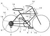
図1に示すように、本発明の自転車用ギア変速システムは、ハンドル14の下方のヘッドチューブ16に設けられた変速指示装置10と、フレームtのトップチューブ17に設けられた電池BOX13と、少なくとも一方のペダル6に設けられた感圧センサ7と、後輪のホイール12のハブ20に設けられたスプロケット2と、スプロケット2のギア1に係合するチェーン3と、フレームtのドロップエンド18に設けられたディレイラ4と、ディレイラ4を可動させるワイヤー部材5とを備えて概略構成されている。 As shown in FIG. 1, the bicycle gear transmission system of the present invention includes a
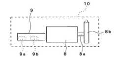
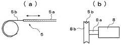
ここで、変速指示装置10は、図2に示すように、モータ8と制御装置9とを備えている。モータ8は、φ35程度のステッピングモータが用いられている。またモータ8の回転軸8aに、φ40のプーリ8bが設けられている。このプーリ8bの外周部には、ワイヤー部材5の一端部側がモータ8の回転により周方向に巻回されている。このワイヤー部材5は、筒状のアウターワイヤ5aと、このアウターワイヤ5a内を摺動可能なインナーワイヤ5bとにより構成され、図3に示すように、インナーワイヤ5bがプーリ8bの外周部に沿って巻回されているとともに、他端部側が変速指示装置10より後輪のホイール12側に延在している。 Here, the
また、制御装置9は、図2に示すように、無線電波を受信する受信部9aと、この受信部9aにより受信した電気信号を計測する計測制御装置9bとを備えている。この計測制御装置9bは、受信部9aより受信した電気信号を計測するとともに、計測した上記踏圧がしきい値の範囲以内であるかを判断し、その判断に基づき、モータ8の回転を制御している。 As shown in FIG. 2, the
そして、電池BOX13は、少なくとも1本以上のアルカリ電池またはリチウムイオン電池が、取出し自在に内装されているとともに、ゴムパッキンなどのシール材により密閉可能に形成されている。そして、電池BOX13には、変速指示装置10に電源を供給するためのコードが設けられている。 The
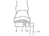
そして、二つのクランク11に回転自在に取り付けられたペダル6に、感圧センサ7が取り付けられている。この感圧センサ7は、少なくとも一方のペダル6に内装されているとともに、感圧センサ7の電気信号を制御装置9に送信する送信部7aを備えている。 A
さらに、後輪のホイール12のハブ20には、図5に示すように、スプロケット2が設けられている。このスプロケット2は、異なる直径を有する複数枚のギア1を同軸上に重ね合わせるとともに、各々のギア1の間にスペーサ2aが設けられている。 Further, as shown in FIG. 5, the
また、ギア1には、環状のチェーン3が係合されている。このチェーン3は、ローラーチェーンが用いられ、クランクと連動したクランクスプロケット19の回転を、後輪のホイール12のハブ20に取り付けられたスプロケット2に伝えている。
なお、ギア1の厚さやスペーサ2aの厚さ、さらにギア1の厚さにスペーサ2aの厚さを加えたスプロケットピンチは、ギア1の段数および製造メーカによって異なる。An
Note that the thickness of the
また、フレームtのドロップエンド18には、ディレイラ4が設けられている。このディレイラ4は、パンタグラフ式であり、プーリ4aをスプロケット2の軸線方向に平行移動させる平方四辺形のリンク機構4bと、上下2個のプーリが設けれたプーリゲージ4cとにより構成されている。また上下2個のプーリは、上側のプーリがチェーン3をスプロケット2のギア1間に案内するガイドプーリであり、下側のプーリがチェーン3の張りを維持するテンションプーリ4dである。さらにディレイラ4には、平方四辺形のリンク機構4bの動きを規制するコイルスプリングと、変速指示装置10のモータ8の回転運動を直線運動に変えるワイヤー部材5のインナーワイヤ5bの他端部側が接続されている。 A
以上の構成による本実施形態の自転車用ギア変速システムによるギア変速方法を、図6のフローチャート図および図1〜図5を用いて説明する。
まず、図6に示すように、自転車kのペダル6に設けられた感圧センサ7の平地運転時での基準踏圧(しきい値)を手動でセットする。この場合、基準踏圧の変動は±20%以内で設定する。A gear transmission method by the bicycle gear transmission system of the present embodiment having the above configuration will be described with reference to the flowchart of FIG. 6 and FIGS.
First, as shown in FIG. 6, the reference pedal pressure (threshold value) at the time of flat ground driving of the pressure-
次に、図1に示す自転車kのサドル14に運転者が腰掛け走行する。このとき、図4に示すように、ペダル6を漕ぐことによって、ペダル6に載せた足の踏圧を感圧センサ7が感知するとともに、その踏圧を電気信号に変えて、送信部7aより制御装置9の受信部9aに無線によって送信する。この際に、制御装置9の計測制御装置9bは、感圧センサ7からの10分間走行時の平均踏圧が基準踏圧の±20%以内であれば、最適踏圧として判断し、モータ8の回転は行われない。 Next, the driver sits on the
しかし、上記基準値踏圧の+20%を超えた場合には、ペダル6に掛かる踏圧が大であることを感圧センサ7から送信された電気信号に基づいて計測制御装置9bが判断し、モータ8を回転させ、回転軸8aに設けられたプーリ8bに巻回されているワイヤー部材5のインナーワイヤ5bを摺動させて、ディレイラ4を可動させ、10分走行時の平均踏圧が、基準踏圧の+20%以下になるまで、ギア1を1枚ずつ架け替えていく。 However, if it exceeds + 20% of the reference pedaling pressure, the
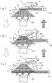
この際のギア1の架け替えは、図5(a)に示すように、小ギア1にチェーン3が係合している場合には、ワイヤー部材5のインナーワイヤ5bをモータ8の回転によって引き、ディレイラ4の平方四辺形のリンク機構4bを規制しているコイルスプリングに抗して、テンションプーリ4dを可動させることにより、図5(b)の中ギア1または図5(c)の大ギア1に移動させ、クランクの回転角とホイールの回転角との比率を変更する。 As shown in FIG. 5A, when the
また、上記基準値踏圧の−20%を未満になった場合には、ペダル6に掛かる踏圧が小であることを感圧センサ7から送信された電気信号に基づいて計測制御装置9bが処理し、モータ8を回転させ、回転軸8aに設けられたプーリ8bに巻回されているワイヤー部材5のインナーワイヤ5bを摺動させて、ディレイラ4を可動させ、10分走行時の平均踏圧が、基準踏圧の−20%以上になるまで、ギア1を1枚ずつ架け替えていく。 When the reference pedal pressure is less than -20%, the
この際のギア1の架け替えは、図5(c)に示すように、大ギア1にチェーン3が係合していた場合には、ワイヤー部材5のインナーワイヤ5bをモータ8の回転によって戻し、ディレイラ4の平方四辺形のリンク機構4bを規制しているコイルスプリングを開放して、テンションプーリ4dを可動させることにより、図5(b)の中ギア1または図5(a)の小ギア1に移動させ、クランクの回転角とホイールの回転角との比率を変更する。 In this case, when the
なお、スプロケット2の直径の異なるギア1は、小ギア1にチェーン3が係合している場合にペダル6が重くなり、大ギア1にチェーン3が係合している場合にペダル6が軽くなる。 Note that the
さらに、急な坂道などに差し掛かり、ペダル6の踏圧に急激な変化が起きた場合には、その急激な変化を感圧センサ7からの電気信号を受信した計測制御装置9bが判断し、すぐさまモータ8を回転させ、回転軸8aに設けられたプーリ8bに巻回されているワイヤー部材5のインナーワイヤ5bを摺動させて、ディレイラ4を可動させ、基準踏圧の±20%以内になるまで、チェーン3をスプロケット2のギア1間を架け替え、クランクの回転角とホイールの回転角とを適切な比率になるまで変更する。 Further, when a sudden change occurs in the pressure applied to the
上述の実施形態による自転車用ギア変速システムによれば、運転者の踏圧をペダル6に設けられた感圧センサ7により感知した電気信号を計測制御装置9bによって計測することにより、モータ8を回転させて、ワイヤー部材5のインナーワイヤ5bを操作しディレイラ4を可動させて、チェーンを移動させスプロケット2のギア1間の架け替えを行うため、坂道などを走行する際に、運転者はハンドル14から手を離すことなく、自動的にディレイラ4を可動させて、クランクの回転角とホイールの回転角とを適切な比率に変更することができる。これにより、運転に集中することができるとともに、安全に走行することができる。 According to the bicycle gear transmission system according to the above-described embodiment, the
また、運転者の10分間走行時の平均踏圧を計測して、クランクの回転角とホイールの回転角とを適切な比率にするため、例えば、起伏の間隔が短い路面では、その都度ギア1の架け替えを行うことにより、チェーン3が外れてしまったり、走行に支障を来すことなく運転することができる。 Further, in order to measure the average pedaling pressure when the driver travels for 10 minutes and to set the crank rotation angle and the wheel rotation angle to an appropriate ratio, for example, on a road surface with a short undulation interval, the
さらに、急な坂道の場合には、その変化に対応してギア1の架け替えを行い、速やかにクランクの回転角とホイールの回転角とを適切な比率に変更することができるため、ペダルが重くなることによって起こる膝への急激な負担を防止することができる。 Furthermore, in the case of a steep slope, the
また、ディレイラ4を可動させるワイヤー部材5のインナーワイヤ5bを動かすモータ8がステッピングモータであるため、スプロケット2の複数枚のギア1を一段ずつ架け替えることができる。この結果、段数の多いスプロケット2でも、確実にチェーン3を架け替えることがでる。 Further, since the
そして、ペダル6に設けられた感圧センサ7が感知した運転者の踏力に応じた電気信号を無線によって、制御装置9の受信部9aに送信することができるため、感圧センサ7自体を密閉した状態でペダル6に装着することができる。これにより、雨天時の走行や水溜まりなどの悪路の走行などにでも、水や泥などにより感圧センサ7が故障したり誤動作したりすることを防止することができる。 And since the electric signal according to the driver | operator's treading force which the pressure-
さらに、制御装置9が感圧センサ7からの電気信号を無線により受信する受信部9aと、受信した電気信号を計測する計測制御装置9bとにより構成されているため、煩雑な配線を必要とせずに、コンパクトに形成することができる。この結果、変速指示装置10の小型化を図ることができるとともに、変速指示装置10を簡便に自転車kに取り付けることができる。 Furthermore, since the
なお、上記実施の形態において、後輪のホイール12にスプロケット2を設けた場合のみ説明したが、これに限定されるものでなく、例えば、クランクスプロケット19に、異なる直径を有する複数枚のギア1を同軸上に重ね合わせ、後輪のホイール12と併用し、クランクの回転角とホイールの回転角とを適切な比率に変更するように構成しても対応可能である。この場合には、後輪のホイール12に設けたスプロケット2と、ギア1を複数枚重ね合わせたクランクスプロケット19とにディレイラ4を各々設けるとともに、各々のディレイラ4を可動させるモータ8を変速指示装置10に設け、制御装置9の計測制御装置9bに設定された基準踏圧によって、各々のモータ8を回転させて、最も適切なクランクの回転角とホイールの回転角との比率になるように、ギア1の架け替えを行うようにする。 In the above embodiment, only the case where the
ディレイラを備えた一般的な自転車、およびスポーツタイプの自転車に利用することができる。 It can be used for general bicycles equipped with a derailleur and sports-type bicycles.
1 ギア
2 スプロケット
3 チェーン
4 ディレイラ
5 ワイヤー部材
5a アウターワイヤ
5b インナーワイヤ
6 ペダル
7 感圧センサ
8 モータ
9 制御装置
9a 受信部
9b 計測制御装置
10 変速指示装置
11 クランク
12 ホイール
k 自転車DESCRIPTION OF
Claims (4)
Translated fromJapanese異なる直径を有する複数枚のギアを同軸上に重ね合わせたスプロケットと、このスプロケットの上記ギアに係合する環状のチェーンと、このチェーンの移動および複数枚の上記ギア間の架け替えを行うディレイラと、このディレイラを可動させるワイヤー部材と、少なくとも一方のペダルに設けられた感圧センサと、上記ワイヤー部材を操作するモータおよび上記感圧センサからの電気信号を処理する制御装置を有する変速指示装置とを備え、
上記変速指示装置は、上記感圧センサにより感知した運転者の踏力に応じた電気信号を受信し、上記制御装置によって当該電気信号を計測するとともに、計測した上記踏圧がしきい値の範囲未満または超えていた場合に、上記モータを回転させ上記ワイヤー部材を操作して上記ディレイラを可動させるとともに、上記チェーンを移動させて上記スプロケットのギア間の架け替えを行い、上記踏圧が上記しきい値の範囲以内になるように、クランクの回転角とホイールの回転角との比率を変更するように構成されていることを特徴とする自転車用ギア変速システム。A gear transmission system for bicycles,
A sprocket in which a plurality of gears having different diameters are coaxially overlapped, an annular chain that engages with the gear of the sprocket, and a derailleur that moves the chain and replaces the plurality of gears A gear member that moves the derailleur, a pressure sensor provided in at least one pedal, a motor that operates the wire member, and a shift instruction device that includes a control device that processes an electrical signal from the pressure sensor. With
The shift instruction device receives an electrical signal corresponding to the driver's pedaling force sensed by the pressure sensor, measures the electrical signal by the control device, and the measured pedaling pressure is less than a threshold range or If so, the motor is rotated and the wire member is operated to move the derailleur, and the chain is moved to replace the sprocket gears. A bicycle gear transmission system configured to change a ratio between a rotation angle of a crank and a rotation angle of a wheel so as to be within a range.
Priority Applications (1)
| Application Number | Priority Date | Filing Date | Title |
|---|---|---|---|
| JP2010181296AJP2012040895A (en) | 2010-08-13 | 2010-08-13 | Gear transmission system for bicycles |
Applications Claiming Priority (1)
| Application Number | Priority Date | Filing Date | Title |
|---|---|---|---|
| JP2010181296AJP2012040895A (en) | 2010-08-13 | 2010-08-13 | Gear transmission system for bicycles |
Publications (1)
| Publication Number | Publication Date |
|---|---|
| JP2012040895Atrue JP2012040895A (en) | 2012-03-01 |
Family
ID=45897699
Family Applications (1)
| Application Number | Title | Priority Date | Filing Date |
|---|---|---|---|
| JP2010181296APendingJP2012040895A (en) | 2010-08-13 | 2010-08-13 | Gear transmission system for bicycles |
Country Status (1)
| Country | Link |
|---|---|
| JP (1) | JP2012040895A (en) |
Cited By (6)
| Publication number | Priority date | Publication date | Assignee | Title |
|---|---|---|---|---|
| CN105109613A (en)* | 2015-08-17 | 2015-12-02 | 深圳市快乐淳科技有限公司 | Speed changing system of intelligent bicycle |
| CN110406619A (en)* | 2019-08-30 | 2019-11-05 | 上海钧正网络科技有限公司 | A bicycle chain state detection device and vehicle |
| JP2022063637A (en)* | 2020-10-12 | 2022-04-22 | 株式会社Subaru | Vehicle rear part structure |
| DE102021214159A1 (en) | 2020-12-25 | 2022-06-30 | Shimano Inc. | CONTROL DEVICE FOR A HUMAN-POWERED VEHICLE |
| JP2022102548A (en)* | 2020-12-25 | 2022-07-07 | 株式会社シマノ | Control device for human-powered vehicles |
| CN115352567A (en)* | 2019-12-18 | 2022-11-18 | 株式会社岛野 | Control device for human-powered vehicle and power transmission system |
Citations (4)
| Publication number | Priority date | Publication date | Assignee | Title |
|---|---|---|---|---|
| JPH0717456A (en)* | 1993-06-30 | 1995-01-20 | Casio Comput Co Ltd | Running condition detector |
| JPH07251786A (en)* | 1991-11-18 | 1995-10-03 | Soc Italiana Catene Calibrate Regina Spa | Bicycle automatic transmission |
| JPH07257473A (en)* | 1994-03-25 | 1995-10-09 | Akebono Brake Ind Co Ltd | Speed change device for bicycle |
| JP2006213268A (en)* | 2005-02-07 | 2006-08-17 | Shimano Inc | Rear derailleur for bicycle |
- 2010
- 2010-08-13JPJP2010181296Apatent/JP2012040895A/enactivePending
Patent Citations (4)
| Publication number | Priority date | Publication date | Assignee | Title |
|---|---|---|---|---|
| JPH07251786A (en)* | 1991-11-18 | 1995-10-03 | Soc Italiana Catene Calibrate Regina Spa | Bicycle automatic transmission |
| JPH0717456A (en)* | 1993-06-30 | 1995-01-20 | Casio Comput Co Ltd | Running condition detector |
| JPH07257473A (en)* | 1994-03-25 | 1995-10-09 | Akebono Brake Ind Co Ltd | Speed change device for bicycle |
| JP2006213268A (en)* | 2005-02-07 | 2006-08-17 | Shimano Inc | Rear derailleur for bicycle |
Cited By (6)
| Publication number | Priority date | Publication date | Assignee | Title |
|---|---|---|---|---|
| CN105109613A (en)* | 2015-08-17 | 2015-12-02 | 深圳市快乐淳科技有限公司 | Speed changing system of intelligent bicycle |
| CN110406619A (en)* | 2019-08-30 | 2019-11-05 | 上海钧正网络科技有限公司 | A bicycle chain state detection device and vehicle |
| CN115352567A (en)* | 2019-12-18 | 2022-11-18 | 株式会社岛野 | Control device for human-powered vehicle and power transmission system |
| JP2022063637A (en)* | 2020-10-12 | 2022-04-22 | 株式会社Subaru | Vehicle rear part structure |
| DE102021214159A1 (en) | 2020-12-25 | 2022-06-30 | Shimano Inc. | CONTROL DEVICE FOR A HUMAN-POWERED VEHICLE |
| JP2022102548A (en)* | 2020-12-25 | 2022-07-07 | 株式会社シマノ | Control device for human-powered vehicles |
Similar Documents
| Publication | Publication Date | Title |
|---|---|---|
| TWI478845B (en) | Bicycle control apparatus | |
| US8831810B2 (en) | Bicycle drive apparatus | |
| JP5566975B2 (en) | Bicycle control device | |
| JP5237421B2 (en) | Bicycle control device | |
| JP5247863B2 (en) | Bicycle control device | |
| TWI669242B (en) | Bicycle transmission apparatus | |
| JP5523636B1 (en) | Electric assist bicycle | |
| JP2012040895A (en) | Gear transmission system for bicycles | |
| JP7738138B2 (en) | Control device for human-powered vehicles | |
| JP6713925B2 (en) | Bicycle drive unit and bicycle drive system including the same | |
| TW201829247A (en) | Bicycle controller and bicycle control system including bicycle controller | |
| JP2019172226A (en) | Control device for man power drive vehicle | |
| JP6941511B2 (en) | Bicycle control device | |
| ITMI20130193A1 (en) | METHOD OF ELECTRONICALLY CHECKING A BICYCLE CHANGE AND ELECTRICALLY ASSISTED BICYCLE CHANGE | |
| TW201623088A (en) | Bicycle transmission control device | |
| CN106414228A (en) | Variable speed structure | |
| JP5685635B2 (en) | Bicycle control device | |
| JP2023092701A (en) | System for detecting tire condition, electric bicycle, method for detecting tire condition, and program | |
| JP2008168881A (en) | Drive structure of electric bicycle | |
| JP7566623B2 (en) | Control device for human-powered vehicle | |
| JP2019202734A (en) | Control apparatus for personally-driven vehicle | |
| KR101665789B1 (en) | Apparatus for arranging chain of bicycle | |
| TW202340030A (en) | Control system for human-powered vehicle capable of enhancing convenience |
Legal Events
| Date | Code | Title | Description |
|---|---|---|---|
| A977 | Report on retrieval | Free format text:JAPANESE INTERMEDIATE CODE: A971007 Effective date:20120622 | |
| A131 | Notification of reasons for refusal | Free format text:JAPANESE INTERMEDIATE CODE: A131 Effective date:20120807 | |
| A02 | Decision of refusal | Free format text:JAPANESE INTERMEDIATE CODE: A02 Effective date:20121204 |