JP2012034717A - Ultrasound image generating apparatus - Google Patents
Ultrasound image generating apparatusDownload PDFInfo
- Publication number
- JP2012034717A JP2012034717AJP2010174635AJP2010174635AJP2012034717AJP 2012034717 AJP2012034717 AJP 2012034717AJP 2010174635 AJP2010174635 AJP 2010174635AJP 2010174635 AJP2010174635 AJP 2010174635AJP 2012034717 AJP2012034717 AJP 2012034717A
- Authority
- JP
- Japan
- Prior art keywords
- echo signal
- depth
- focus
- ultrasonic wave
- ultrasonic
- Prior art date
- Legal status (The legal status is an assumption and is not a legal conclusion. Google has not performed a legal analysis and makes no representation as to the accuracy of the status listed.)
- Granted
Links
Images


Classifications
- A—HUMAN NECESSITIES
- A61—MEDICAL OR VETERINARY SCIENCE; HYGIENE
- A61B—DIAGNOSIS; SURGERY; IDENTIFICATION
- A61B8/00—Diagnosis using ultrasonic, sonic or infrasonic waves
- A61B8/08—Clinical applications
- A61B8/0833—Clinical applications involving detecting or locating foreign bodies or organic structures
- A61B8/0841—Clinical applications involving detecting or locating foreign bodies or organic structures for locating instruments
- A—HUMAN NECESSITIES
- A61—MEDICAL OR VETERINARY SCIENCE; HYGIENE
- A61B—DIAGNOSIS; SURGERY; IDENTIFICATION
- A61B8/00—Diagnosis using ultrasonic, sonic or infrasonic waves
- A61B8/52—Devices using data or image processing specially adapted for diagnosis using ultrasonic, sonic or infrasonic waves
- A61B8/5269—Devices using data or image processing specially adapted for diagnosis using ultrasonic, sonic or infrasonic waves involving detection or reduction of artifacts
- G—PHYSICS
- G01—MEASURING; TESTING
- G01S—RADIO DIRECTION-FINDING; RADIO NAVIGATION; DETERMINING DISTANCE OR VELOCITY BY USE OF RADIO WAVES; LOCATING OR PRESENCE-DETECTING BY USE OF THE REFLECTION OR RERADIATION OF RADIO WAVES; ANALOGOUS ARRANGEMENTS USING OTHER WAVES
- G01S7/00—Details of systems according to groups G01S13/00, G01S15/00, G01S17/00
- G01S7/52—Details of systems according to groups G01S13/00, G01S15/00, G01S17/00 of systems according to group G01S15/00
- G01S7/52017—Details of systems according to groups G01S13/00, G01S15/00, G01S17/00 of systems according to group G01S15/00 particularly adapted to short-range imaging
- G01S7/52046—Techniques for image enhancement involving transmitter or receiver
Landscapes
- Health & Medical Sciences (AREA)
- Life Sciences & Earth Sciences (AREA)
- Engineering & Computer Science (AREA)
- Physics & Mathematics (AREA)
- Molecular Biology (AREA)
- Heart & Thoracic Surgery (AREA)
- Veterinary Medicine (AREA)
- Public Health (AREA)
- Biophysics (AREA)
- Nuclear Medicine, Radiotherapy & Molecular Imaging (AREA)
- Pathology (AREA)
- Radiology & Medical Imaging (AREA)
- Biomedical Technology (AREA)
- General Health & Medical Sciences (AREA)
- Medical Informatics (AREA)
- Animal Behavior & Ethology (AREA)
- Surgery (AREA)
- Computer Networks & Wireless Communication (AREA)
- Remote Sensing (AREA)
- General Physics & Mathematics (AREA)
- Radar, Positioning & Navigation (AREA)
- Computer Vision & Pattern Recognition (AREA)
- Ultra Sonic Daignosis Equipment (AREA)
Abstract
Translated fromJapaneseDescription
Translated fromJapanese本発明は、超音波画像生成装置に関し、特に生体組織と共に穿刺器具を画面上に表示する超音波画像生成装置に関する。 The present invention relates to an ultrasonic image generation apparatus, and more particularly to an ultrasonic image generation apparatus that displays a puncture device on a screen together with a living tissue.
医療分野において、超音波画像生成装置が診察や検査に広く用いられている。超音波画像生成装置は、超音波探触子と共に用いられ、超音波探触子から被検者に超音波を照射し、被検者から反射したエコー信号から被検者の超音波断層画像(以下、超音波画像という)を生成する装置である。 In the medical field, ultrasonic image generating apparatuses are widely used for examinations and examinations. The ultrasonic image generation device is used together with an ultrasonic probe, irradiates a subject with ultrasonic waves from the ultrasonic probe, and receives an ultrasonic tomographic image of the subject from an echo signal reflected from the subject ( Hereinafter, it is an apparatus that generates an ultrasound image).
超音波探触子は、アレイ状に配列された複数の圧電素子からなる圧電素子アレイを有し、圧電素子アレイから被検者に超音波を照射するとともに、被検者からのエコー信号を受信する。超音波画像生成装置は、超音波探触子が受信したエコー信号に基づいて、被検者の超音波画像を生成してモニタに表示する。 The ultrasonic probe has a piezoelectric element array composed of a plurality of piezoelectric elements arranged in an array, and irradiates the subject with ultrasonic waves from the piezoelectric element array and receives echo signals from the subject. To do. The ultrasonic image generating device generates an ultrasonic image of the subject based on the echo signal received by the ultrasonic probe and displays the ultrasonic image on the monitor.
超音波画像生成装置においては、特定の撮像ターゲットを高精細に見るため、電子フォーカスにより焦点位置を撮像ターゲットの位置に合わせることが行われる。 In the ultrasonic image generating apparatus, in order to view a specific imaging target with high definition, the focal position is adjusted to the position of the imaging target by electronic focusing.
電子フォーカスとは、複数の圧電素子から出た超音波が焦点位置において同位相で重なり合うよう当該複数の圧電素子を時間差駆動させ、同様に当該複数の圧電素子で受信した焦点位置からのエコー信号が時間的に同位相となるように遅延加算することを言う。焦点位置近傍では、高い分解能の断層画像情報が取得される。 Electronic focusing means that the plurality of piezoelectric elements are driven with a time difference so that the ultrasonic waves emitted from the plurality of piezoelectric elements overlap in phase at the focal position, and similarly, echo signals from the focal position received by the plurality of piezoelectric elements are This means that delay addition is performed so as to be in phase in time. In the vicinity of the focal position, high-resolution tomographic image information is acquired.
また、超音波画像生成装置においては、確定診断のために穿刺針を所望の部位に穿刺して組織サンプルを採取する穿刺術が行われる。穿刺術を行う場合、穿刺をするための穿刺ガイドラインを表示部に表示し、圧電素子アレイの配列方向に電子フォーカスの焦点位置を変化させることで、焦点の深度方向の目的とする位置で高い分解能の断層画像情報を取得する装置が開示されている(特許文献1参照)。 In addition, in the ultrasonic image generating apparatus, a puncture technique is performed in which a puncture needle is punctured at a desired site to collect a tissue sample for definitive diagnosis. When performing puncture, puncture guidelines for puncture are displayed on the display unit, and by changing the focus position of the electronic focus in the direction of arrangement of the piezoelectric element array, high resolution at the target position in the depth direction of focus An apparatus for acquiring tomographic image information is disclosed (see Patent Document 1).
しかしながら、特許文献1に記載の装置は、電子フォーカスの焦点が合っている部分の画質は良いが、焦点が合っていない部分の画質は良くない。特に、医師が穿刺針を刺しながら超音波画像を確認する場合は、穿刺針に焦点を合わせて穿刺針を見やすくすることも重要であるが、焦点が合っていない部分の画質も良くなければ、周辺組織の視認性が劣るため穿刺の効率も悪くなる。 However, the apparatus described in
本発明は、上記事実に鑑みてなされたものであり、超音波画像全体における画質の劣化を防ぐとともに、穿刺針等の撮像ターゲット周辺においても画質が良い超音波画像を生成できる超音波画像生成装置を提供することを目的とする。 The present invention has been made in view of the above-described facts, and prevents an image quality deterioration in the entire ultrasound image and can generate an ultrasound image with a good image quality around an imaging target such as a puncture needle. The purpose is to provide.
上記目的を達成するために、本発明に係る超音波画像生成装置は、探触子に超音波の送受信を行わせる探触子制御手段と、探触子によって送受信される超音波の焦点を送信音線毎に制御する焦点制御手段と、を備え、探触子制御手段は、焦点制御手段によって焦点の位置を撮像ターゲットの位置とした第一の超音波、および焦点の位置を一様な位置とした第二の超音波の送信を探触子に行わせ、さらに、第一の超音波の送信によって受信された第一のエコー信号、および第二の超音波の送信によって受信された第二のエコー信号の重み付け加算を行い、合成エコー信号を得る重み付け加算手段と、重み付け加算手段によって得られた合成エコー信号から超音波画像を生成する画像生成手段と、を備える構成を採る。 In order to achieve the above object, an ultrasonic image generating apparatus according to the present invention transmits probe control means for causing a probe to transmit and receive ultrasonic waves, and a focus of ultrasonic waves transmitted and received by the probe. A focus control unit that controls each sound ray, and the probe control unit uses the focus control unit to set the first ultrasonic wave with the focus position as the position of the imaging target, and the focus position to a uniform position. The probe transmits the second ultrasonic wave, the first echo signal received by the first ultrasonic wave transmission, and the second ultrasonic wave received by the second ultrasonic wave transmission. The weighting addition means for performing the weighted addition of the echo signals and obtaining the synthesized echo signal and the image generating means for generating the ultrasonic image from the synthesized echo signal obtained by the weighted addition means are employed.
また、重み付け加算手段は、第一の超音波における送信音線毎の焦点の深さ、および第二の超音波における送信音線毎の焦点の深さの双方に基づいて、重み付け加算で使用される重みを、第一のエコー信号および第二のエコー信号における受信音線毎に決定する。 The weighted addition means is used in the weighted addition based on both the depth of focus for each transmission sound ray in the first ultrasonic wave and the depth of focus for each transmission sound ray in the second ultrasonic wave. Is determined for each reception sound ray in the first echo signal and the second echo signal.
また、重み付け加算手段は、重み付け加算を行う第一のエコー信号および第二のエコー信号における受信音線の深度の増加に応じて、重み付け加算で使用される重みを変化させる。 Further, the weighted addition means changes the weight used in the weighted addition according to the increase in the depth of the received sound ray in the first echo signal and the second echo signal to be weighted.
本発明によれば、穿刺針等の撮像ターゲットを強調し、超音波画像全体における画質の劣化を防ぐとともに、撮像ターゲット以外の領域においても画質の良い超音波画像を生成することができる。 According to the present invention, it is possible to emphasize an imaging target such as a puncture needle, prevent deterioration of image quality in the entire ultrasound image, and generate an ultrasound image with good image quality in a region other than the imaging target.
以下、添付図面を参照しながら本発明の実施の形態について説明する。 Hereinafter, embodiments of the present invention will be described with reference to the accompanying drawings.
(実施の形態1)
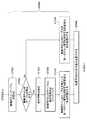
図1は、本発明の実施の形態1に係る超音波画像生成装置100の構成を示した機能ブロック図である。
同図に示される超音波画像生成装置100は、ユーザ入力部102、CPU104、穿刺針情報記憶部106、電子フォーカス制御部108、送信ビームフォーマ110、受信ビームフォーマ112、送受信部114、画像記憶部116、加算比率演算部118、重み付け加算処理部120および画像表示制御部122を含む。画像記憶部116は、第一のエコー信号記憶部124および第二のエコー信号記憶部126を含む。(Embodiment 1)
FIG. 1 is a functional block diagram showing a configuration of an ultrasonic
The ultrasonic
図1には、超音波画像生成装置100と共に使用される探触子128、穿刺アダプタ130およびモニタ132も示してある。探触子128は、複数の圧電素子からなる圧電素子アレイ(図2参照)を含み、超音波の送受信を行う。穿刺アダプタ130は、探触子128に接続され、穿刺針を特定の角度で被検者に刺入させるガイドとなる。具体的には、穿刺アダプタに設けられた穴に沿って穿刺針が動くことで、穿刺針が特定の方向に動く。穿刺アダプタ130は、探触子128から着脱交換が可能となっており、穿刺アダプタ130の種類によって使用できる穿刺針の太さが異なる。また、穿刺アダプタ130の種類によって、穿刺針を被検者に刺入する角度(以下、これを刺入角度という)または被検者に刺入する位置(以下、これを刺入位置という)が異なる。被検者への刺入角度および刺入位置が決まれば、刺入する経路(以下、これを刺入経路という)が決まる。従って、穿刺アダプタ130を交換することで、使用できる穿刺針の太さ、刺入角度、刺入位置または刺入経路を変更できる。穿刺アダプタ130内には記憶部があり、予め自身が使用できる穿刺針の太さ、刺入角度の情報を記憶している。穿刺アダプタ130は、探触子128へ接続されると、穿刺針の太さ、刺入角度または刺入位置を探触子128へ出力する。 FIG. 1 also shows a
ユーザ入力部102は、ユーザからの入力を受け付ける部分であり、穿刺針の太さや刺入角度等の穿刺針に関する情報の入力を受け付け、その情報(S101)をCPU104へ出力する。ユーザ入力部102は、例えば入力スイッチやキーボード等である。 The
CPU104は、超音波画像生成装置100における動作の制御やメモリへの書き込み等を行う。ユーザ入力部102から出力された穿刺針に関する情報(S101)を受けたCPU104は、当該穿刺針に関する情報を穿刺針情報記憶部106に記憶する。また、CPU104は、穿刺アダプタ130から探触子128を経由して出力された穿刺針に関する情報(S103)を、穿刺針情報記憶部106に記憶する。ここで、穿刺針に関する情報は、具体的には、穿刺針の太さ、刺入角度、刺入位置または刺入経路である。 The
超音波画像生成装置100は、穿刺針に関する情報を用いて穿刺針上および穿刺針の延長線上に超音波の焦点を合わせて取得したエコー信号と、一様な位置に超音波の焦点を合わせて取得したエコー信号とから合成エコー信号を生成する。ここで、一様な位置とは、全域に分散していない位置をいう。例えば、焦点位置を一定の深度に揃える場合や、画像の左から右に向けて徐々に焦点の位置が浅くなる場合、局所的に焦点の位置を浅くする場合等をいう。以下、撮像ターゲットに焦点を合わせて取得したエコー信号を第一のエコー信号(ターゲット強調画像データ)といい、一様な位置に焦点を合わせて取得したエコー信号を第二のエコー信号という。第一のエコー信号に補間等の処理を行って画像信号に変換して生成したBモード画像を第一の画像(ターゲット強調画像)といい、第二のエコー信号を画像信号に変換して生成したBモード画像を第二の画像という。本実施の形態では、第一の画像において、穿刺針を撮像ターゲットとして、超音波の焦点位置を穿刺針上および穿刺針の延長線上に合わせ、第二の画像においては、一定の深度に超音波の焦点位置を揃えた場合を代表例にとって説明を行う。本実施の形態では、第一の画像と第二の画像との画像サイズは同じである。 The ultrasonic
CPU104は、穿刺針情報記憶部106に記憶された穿刺針に関する情報を基に、穿刺針の刺入経路に合わせた焦点位置を決定し、焦点位置を指示する信号を電子フォーカス制御部108へ出力する。また、CPU104は、予め定められている一様な焦点位置を電子フォーカス制御部108へ出力する。例えば、乳房のような50mmの視野深度であれば、焦点位置を20mmの深度に一定とする。ここで、視野深度とは、被検者の表面からの深さであり、エコー信号を取得する深さを表す。 The
電子フォーカス制御部108は、電子フォーカスを制御する部分である。電子フォーカス制御部108は、CPU104によって決定された焦点位置に基づいて、探触子128内にある各圧電素子の駆動タイミングを演算し、送信ビームフォーマ110へ出力する。また、電子フォーカス制御部108は、エコー信号の発生した深度に応じたエコー信号の遅延加算における遅延量を受信ビームフォーマ112に出力する。 The electronic
送信ビームフォーマ110は、送受信部114内にあるパルサを駆動して、電子フォーカス制御部108によって指定された送信ビームを探触子128に形成させるものである。すなわち、送信ビームフォーマ110は、電子フォーカス制御部108から出力された各圧電素子の駆動タイミングに従い、送受信部114内にあるパルサを駆動する命令を送受信部114へ出力する。 The transmission beam former 110 drives a pulser in the transmission /
送受信部114は探触子128と信号の送受信を行う。送受信部114は、探触子128内にある圧電素子を駆動するための高電圧の電気信号を発生するパルサ、増幅器、ローパスフィルタおよびA/D変換部を有する。送受信部114は、送信ビームフォーマ110から出力された命令に基づいてパルサを駆動し、探触子128へ圧電素子を駆動する電気信号(以下、圧電素子駆動信号という)を出力する。また、送受信部114は、探触子128から出力された信号を増幅し、ローパスフィルタで高周波成分をカットし、A/D変換した後に、受信ビームフォーマ112に出力する。 The transmission /
探触子128は、被検者へ超音波を送受信する部分であり、患者等の被験者に接触させて使用する。探触子128は、複数の圧電素子からなる圧電素子アレイおよびアナログマルチプレクサを有し、複数の圧電素子によって超音波の送受信を行う。探触子128は、送受信部114から出力される電気信号を基に、駆動する圧電素子を順次切り替えながら電子走査を行う。また、探触子128は、超音波が被検者によって反射されたエコー信号を圧電素子で受信し、電気信号に変換して送受信部114へ出力する。 The
受信ビームフォーマ112は、フォーカス制御部108から出力された遅延量に従い、送受信部114から出力されたエコー信号を、エコー信号が発生した位置に応じて遅延させ、位相を揃えて加算して受信音線を生成する(以下、位相を揃えて加算されたエコー信号を受信音線という)。受信ビームフォーマ112は、受信音線が生成された第一のエコー信号を第一のエコー信号記憶部124へ記憶し、第二のエコー信号を第二のエコー信号記憶部126へ記憶する。 The reception beamformer 112 delays the echo signal output from the transmission /
加算比率演算部118は、第一のエコー信号と第二のエコー信号との加算比率を演算する。加算比率演算部118は、CPU104から出力される焦点位置を基に、第一のエコー信号と第二のエコー信号とを加算する比率を演算して、重み付け加算処理部120へ出力する。これにより、第一のエコー信号と第二のエコー信号とを望ましい比率で重み付け加算を行った合成画像が得られる。 The addition
重み付け加算処理部120は、加算比率演算部118から出力された加算比率に基づいて、第一のエコー信号記憶部124に記憶されている第一のエコー信号と、第二のエコー信号記憶部126に記憶されている第二のエコー信号との重み付け加算を行い、画像表示制御部122へ出力する。 The weighted
画像表示制御部122は、エコー信号(受信音線)から、被検体内の組織に関する断層画像情報である画像信号を生成する。画像表示制御部122は、STC(sensitivity time control)と、DSC(digital scan converter:デジタルスキャンコンバータ)とを含む。STCは、重み付け加算処理部120によって生成される合成エコー信号に対して、超音波の反射位置の深度に応じて距離による減衰の補正を施す。また、DSCは、STCによって補正された画像データを通常のテレビジョン信号の走査方式に従う方式に変換(ラスター変換)し、階調処理等の必要な画像処理を施すことにより、画像信号を生成する。画像表示制御部122によって生成される画像信号に基づいて、モニタ132に超音波画像が表示される。 The image
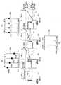
図2は、探触子128および受信ビームフォーマ112の詳細な構成を示した模式図である。探触子128は、アナログマルチプレクサ134および圧電素子アレイ138を含む。なお、この図では穿刺アダプタ130および穿刺アダプタ130から出力される信号は省略してある。 FIG. 2 is a schematic diagram showing detailed configurations of the
圧電素子アレイ138内には、複数の圧電素子(図2では138a〜138fの6つのみ示す)があり、それらが一次元上に配列されている。複数の圧電素子(例えば138a〜138f)は、それぞれ対応するアナログマルチプレクサ134の出力端子(例えば136a〜134f)と接続されている。 In the
アナログマルチプレクサ134は、アナログ電子スイッチであり、送受信部114と信号のやり取りをする5チャネルの入出力端子(図2では134a〜134eで示す)および圧電素子アレイ138内の複数の圧電素子と一対一に接続され信号のやり取りをする複数の入出力端子を有する。ここでは入出力端子136a〜136fで示す6つの入出力端子について説明する。アナログマルチプレクサ134は、送受信部114と接続される5チャネルの入出力端子134a〜134eと、圧電素子アレイ138と接続される複数の入出力端子136a〜136fとの接続を切り替えることで、駆動する圧電素子を選択する。例えば、入出力端子134aと入出力端子136aを接続すれば、圧電素子138aを駆動することができる。本実施の形態では、アナログマルチプレクサ134により接続された5つの圧電素子により超音波の送信を行う。 The
送信ビームフォーマ110からの命令(S201)を受けた送受信部114は、圧電素子指定信号(S203)をアナログマルチプレクサ134へ出力する。なお、本来はアナログマルチプレクサ134の5チャネルの入出力端子に対応した5種の信号が送受信部114から出力されるが、ここでは図を分かりやすくするために一つの矢印で示した。 Upon receiving the command (S201) from the
アナログマルチプレクサ134は、送受信部114から出力された、圧電素子指定信号(S203)を基に、送受信部114と接続されている5チャネルの入出力端子134a〜134eと、圧電素子アレイ138と接続されている複数の入出力端子136a〜136fとの接続を行う。ここでは、入出力端子134aと136a、134bと136b、・・・134eと136eとをそれぞれ接続した図を示した。すなわち、入出力端子134a、入出力端子136aおよび圧電素子138aのように、同じアルファベットを付した要素が一つのラインとなって接続される。 The
送受信部114は、送信ビームフォーマ110から出力された命令を基に、圧電素子毎に駆動タイミングを異ならせた圧電素子駆動信号(S203)を内部のパルサから出力する。圧電素子138a〜138eは、圧電素子駆動信号によって指定されたタイミングで超音波を照射し、予め決められた位置に焦点が合った超音波を送信する。すなわち、圧電素子138a〜138eから出力された超音波は、CPU104によって指定された焦点位置140で同位相となり焦点が合う。このようにして、超音波画像生成装置100は、所望の位置に焦点が合う超音波を探触子128から照射させる。図2の矢印142は、圧電素子138a〜138eによって送信される超音波の感度分布の中心線を表し、送信音線という。 Based on the command output from the
圧電素子138a〜138eは、超音波の照射により被検者から反射されたエコー信号を受信し、電気信号に変換してアナログマルチプレクサ134から送受信部114へ送信する。送受信部114は、エコー信号を増幅してローパスフィルタを通し、A/D変換を行って受信ビームフォーマ112内の遅延回路144へ出力する。 The
圧電素子138a〜138eは、矢印142からの距離が異なるため、矢印142上の各点で発生したエコー信号を異なるタイミングで受信する。遅延回路144は、エコー信号の遅延を行い、圧電素子138a〜138eから出力されたエコー信号が時間的に同位相となるようにする。この例では、圧電素子138cが矢印142から最も近いため、圧電素子138cが出力したエコー信号を最も大きく遅延させ、圧電素子138bおよび138dが出力したエコー信号も遅延させることで、圧電素子138aおよび138eが出力したエコー信号とその他の圧電素子が出力したエコー信号が時間的に同位相となるようにする。 Since the
加算回路146は、同位相となったエコー信号の加算を行い、受信音線を生成して、画像記憶部116へ出力する。このようにして、受信ビームフォーマ112は、圧電素子で受信されるエコー信号を遅延加算して受信音線を生成する。受信音線に対し、補間等の処理を行って画像信号に変換することで、超音波画像が生成できる。 The
アナログマルチプレクサ134は、内部の端子の接続を切り替えることで、使用する圧電素子を、圧電素子が配列される配列方向に一つずつずらして電子走査を行う。すなわち、送信音線142により送信した超音波のエコー信号を受信した後、アナログマルチプレクサ134は、入出力端子134aと入出力端子136b、入出力端子134bと入出力端子136c、・・134eと136fを接続し、次に使用される圧電素子は138b〜138fとなる。圧電素子138b〜138fは、CPU104によって指定された焦点位置で同位相となるタイミングで超音波を照射する。この電子走査により、送信音線の位置は圧電素子の配列方向に所定の間隔だけずれる。超音波画像生成装置100は、このようにして探触子128に電子走査を行わせて複数のエコー信号を取得し、エコー信号を画像信号に変換することで二次元画像を作成する。 The
超音波画像生成装置100は、第一の画像においては送信音線ごとに穿刺針上および穿刺針の延長線上に焦点を合わせ、第二の画像においては予め決められた一様な位置に焦点を合わせて超音波の送受信を行う。 The ultrasonic
図3は、本実施の形態に係る超音波画像生成装置100における画像処理の概要を示した模式図である。具体的には、送信ビーム150を用いてエコー信号である第二のエコー信号158を取得し、送信ビーム154を用いて第一のエコー信号160を取得し、第二のエコー信号158と第一のエコー信号160とを加算して、合成エコー信号162を取得する流れを示した図である。図3に示される送信ビーム150および送信ビーム154は、探触子128から送信される超音波の送信音線を探触子128の走査方向に並べて描かれたものであり、ここでは図面を分かりやすくするために上辺および下辺を加えて描かれている(以下の送信音線および受信音線の図示においても同様)。 FIG. 3 is a schematic diagram showing an outline of image processing in the ultrasonic
送信ビーム150は、送信音線150a〜150fを有し、送信ビーム154は、送信音線154a〜154fを有する。黒丸152a〜152fおよび黒丸156a〜156fは、対応する送信音線150a〜150fおよび送信音線154a〜154f上の焦点位置を表す。例えば、送信音線150a上における焦点は、焦点152aの位置にあり、送信音線152b上における焦点は、焦点152bの位置にある。送信ビーム150において、焦点152a〜152fは同じ深度にある。送信ビーム154において、焦点156a〜焦点156fは穿刺針上および穿刺針の延長線上に位置する。ここでは、送信ビーム150の上辺が探触子128と患者等の被験者が接する位置を表し、送信ビーム150の下辺が視野深度の最大値(最大視野深度)を表す。最大視野深度とは、超音波画像を取得する最大の深度のことである。最大視野深度は、エコー信号を取得する深度によって決まるものであり、ユーザが設定することができる。 The
超音波画像生成装置100は、焦点の位置を一定の深度に揃えた送信ビーム150を用いて第二のエコー信号158を取得し、焦点の位置を穿刺針上および穿刺針の延長線上に合わせた送信ビーム154を用いて第一のエコー信号160を取得する。第二のエコー信号158は受信音線158a〜158fを有し、第一のエコー信号160は、受信音線160a〜160fを有する。受信音線158a〜158fと送信音線150a〜150fとは、それぞれ対応しており、受信音線158aにおいて焦点が合っている深度は、焦点152aの深度となる。すなわち、受信音線158aにおいては、焦点152aの深度の位置が最も画質が良い。また、受信音線160a〜160fと送信音線154a〜154fとの関係も、送信音線158a〜158fと受信音線150a〜150fとの関係と同様である。 The ultrasonic
このようにして取得した第二のエコー信号158は、画像全体として一定の深度に焦点が揃った画像となるため、特定の撮像ターゲットを強調する画像とはならない。一方、第一のエコー信号160は、穿刺針上および穿刺針の延長線上に焦点があるため、穿刺針および穿刺針の延長線上において画質の良い画像となる。 The
超音波画像生成装置100は、第二のエコー信号158(受信音線158a〜158f)と第一のエコー信号160(受信音線160a〜160f)とを、受信音線ごとに重み付け加算を行って合成エコー信号162(受信音線162a〜162f)を求める。具体的には、受信音線158aと受信音線160aとの重み付け加算を行って受信音線162aとし、受信音線158bと受信音線160bとの重み付け加算を行って受信音線162bとする。その他の受信音線も同様に重み付け加算を行い、合成エコー信号162を生成する。つまり、第二のエコー信号158と、第一のエコー信号160とを適切な重みで加算することで、所望の合成エコー信号を生成する。なお、ここでは説明を分かりやすくするために送信音線および受信音線の数を6本とした。 The ultrasonic
図4に示したフロー図を用いて、本実施の形態に係る超音波画像生成装置100の動作の概要および作用を説明する。まず、装置の電源をONし、ステップST402で走査位置ごとに焦点位置を制御するモードをONにする。ステップST404で第一のエコー信号を取得する超音波の焦点位置を決定し、ステップST406で重み付け加算のための重みを算出する。ステップST408で、ステップST404によって決定された焦点位置で超音波の送受信を行って第一のエコー信号を取得し、ステップST410で、予め決められた一定の焦点位置で超音波の送受信を行って第二のエコー信号を取得する。ステップST412で第一のエコー信号と第二のエコー信号との重み付け加算を行い、得られた合成エコー信号をステップST414で画像信号に変換して、モニタ132に表示する。ここで、第二のエコー信号と第一のエコー信号とは、異なるタイミングで取得する。 The outline and operation of the operation of the ultrasonic
図5に示したフロー図を用いて、第一のエコー信号を取得する超音波の焦点位置を決定するステップST404の動作について詳細に説明する。 With reference to the flowchart shown in FIG. 5, the operation of step ST404 for determining the focal position of the ultrasonic wave for acquiring the first echo signal will be described in detail.
超音波画像生成装置100は、穿刺針情報記憶部106に記憶された穿刺針の太さ、刺入角度、刺入位置、または刺入経路から、穿刺針に焦点を合わせるためのテーブルを作成し、穿刺針情報記憶部106に記憶しておく(以下、穿刺針に焦点を合わせるためのテーブルを、制御用ラインテーブルという)。超音波画像生成装置100は、穿刺針情報記憶部106に記憶された制御用ラインテーブルに基づいて第一のエコー信号を取得する超音波の焦点位置を決定する。このようにして、超音波画像生成装置100は、穿刺針の刺入経路上および刺入経路の延長線上に焦点を合わせる。 The ultrasonic
ステップST400で、走査位置ごとに焦点位置を制御するモードをONにすると、ステップST500で、制御用ラインテーブルを読み出す。ステップST502で、読みだした制御用ラインテーブルの補正をするかどうかをユーザに問い、制御用ラインテーブルを補正しない場合はステップST504へ進み、ステップST504で制御用ラインテーブルを第一のエコー信号を取得する超音波の焦点位置としてステップST406へ進む。 When the mode for controlling the focal position for each scanning position is turned ON in step ST400, the control line table is read in step ST500. In step ST502, the user is asked whether or not to correct the read control line table. If the control line table is not corrected, the process proceeds to step ST504. In step ST504, the control line table is sent to the first echo signal. The process proceeds to step ST406 as the focal position of the ultrasonic wave to be acquired.
ステップST502で制御用ラインテーブルを補正する場合は、ステップST506で穿刺針の特徴点の抽出を行い、ステップST508で制御用ラインテーブルと穿刺針の特徴点とのフィッティングを行う。ステップST510で制御用ラインテーブルを補正して第一のエコー信号を取得する超音波の焦点位置としてステップST406へ進む。ステップST406では、重み付け加算のための重みを算出する。超音波画像生成装置100は、補正された制御用ラインテーブルが示す位置に焦点を合わせて第一のエコー信号を取得する。このように制御用ラインテーブルの補正を行うと、穿刺アダプタによって決まる刺入経路から穿刺針がずれた場合においても、穿刺針に焦点を合わせた第一のエコー信号を取得することができる。穿刺針が刺入経路からずれる原因としては、アダプタ自身の遊びや、組織の抵抗による穿刺針の撓み等がある。ステップST506で行う穿刺針の特徴点の抽出は、異なる画像間のフレーム差分を取ることで、穿刺針の位置を特定することが考えられる。 When correcting the control line table in step ST502, feature points of the puncture needle are extracted in step ST506, and fitting of the control line table and the feature points of the puncture needle is performed in step ST508. In step ST510, the control line table is corrected to obtain the first echo signal, and the process proceeds to step ST406. In step ST406, a weight for weighted addition is calculated. The ultrasonic
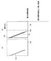
ステップST406の重み付け加算のための加算比率算出について、図6(A)〜(G)を用いて説明する。第一のエコー信号164および第二のエコー信号166を重み付け加算した結果得られる合成エコー信号170の受信音線Lは、L=(1−p)×a+p×bの式で与えられる。ここで、aは、第一のエコー信号164の受信音線、bは第二のエコー信号166の受信音線を表し、pは第二のエコー信号の重みを表す。 The addition ratio calculation for weighted addition in step ST406 will be described with reference to FIGS. The reception sound ray L of the synthesized
加算比率を決定する基本的な考え方は、第二のエコー信号の焦点が合っている位置を重み1として、第一のエコー信号の焦点が合っているところを重み0とする。すなわち、第二のエコー信号の焦点が合っている位置は、第二のエコー信号を合成エコー信号とし、第一のエコー信号の焦点が合っている位置は、第一のエコー信号を合成エコー信号とする。このように制御すると、焦点が合っている位置の画像は、合成画像として使用されるので画質が良い。 The basic idea for determining the addition ratio is that the position where the second echo signal is in focus is
ここでは、4本の受信音線からなり、最大視野深度が同一な、第一のエコー信号164および第二のエコー信号166を重み付け加算する場合を考える。例えば、図6(G)に示す合成エコー信号170の左端の受信音線170aを計算する場合は、図6(E)に示す第一のエコー信号164の左端の受信音線164aと、図6(F)に示す第二のエコー信号166の左端の受信音線166aとの重み付け加算を行う。具体的には、受信音線164aと受信音線166aとを、図6(A)に示すグラフ168aで示す重みによって加算を行う。例えば、受信音線170aにおいて、図6(A)に示すように、深度0から焦点163aの深度までの領域(第一の領域)は、重み168aの値が0であるため、受信音線164aのデータが受信音線170aのデータとなり、焦点165aの深度より深い領域(第三の領域)では、重み168aの値が1であるため、受信音線166aのデータが受信音線170aのデータとなる。 Here, a case is considered where the
図6(A)に示すように、焦点163aの深度から焦点165aの深度までの間の領域(第二の領域)は、重み168aが0から1へ滑らかに変化し、その重みに従って受信音線164aと受信音線166aとが上記Lの式で加算され、その結果が受信音線170aのデータとなる。すなわち、焦点163aの深度から焦点165aの深度までの間は、深度の増加に伴って第二のエコー信号166の重みを増加させる。これは、第一のエコー信号の焦点163aの深度から第二のエコー信号の焦点165aに近づくほど、第二のエコー信号の画質が良くなるためである。換言すれば、第一のエコー信号164と、第二のエコー信号166との画質差を重みに反映させ、焦点位置に近く画質が良い画像データ程、重みを増加させる。このように、深度に応じて重み付け加算の重みを変化させると、焦点163aの深度から焦点165aの深度までの間の領域において受信音線170aのデータを深度方向に滑らかに繋ぐことができる。すなわち、視野深度毎の第一のエコー信号164と第二のエコー信号166との画質差を考慮して、画質が良い方の画像の重みを増加させて重み付け加算を行い、合成エコー信号170を作成しているため、合成画像の画質が良い。 As shown in FIG. 6A, in a region (second region) between the depth of the
同様に、受信音線170bを計算する場合は、第一のエコー信号164の受信音線164bと、第二のエコー信号166の受信音線166bとを図6(B)に示す重み168bに従って加算を行う。すなわち、受信音線170bにおいて、図6(B)に示すように、深度0の位置から焦点165bの深度までの領域(第一の領域)は、重み168bの値が1であるため、受信音線166bのデータが受信音線170bのデータとなり、焦点163bの深度より深い領域(第三の領域)では、重み168bの値が0となるため、受信音線164bのデータが受信音線170bのデータとなる。焦点165bの深度から焦点163bの深度までの間の領域(第二の領域)は、重み168bが1から0へ滑らかな曲線で変化し、その重みに従って受信音線164bと受信音線166bとが上記Lの式で加算され、その結果が受信音線170bのデータとなる。すなわち、焦点165bの深度から焦点163bの深度までの間は、深度の増加に伴い第一のエコー信号164の重みを増加させる。これは、第一のエコー信号164の焦点163bに近づくほど、第一のエコー信号164の画質が良くなるためである。受信音線170cおよび受信音線170dについても、受信音線170bの場合と同様に、図6(C)に示す重み168cを用いた受信音線164cと166cとの重み付け加算および図6(D)に示す重み168dを用いた受信音線164dと166dとの重み付け加算を行って求める。このようにして重みを変化させながら重み付け加算を行えば、画像全体の画質を維持しながら、撮像ターゲットである穿刺針および穿刺針の延長線上に焦点の合った画像を生成することができる。また、第三の領域では、焦点位置が近い方の画像のみを使うため、画質が良い。 Similarly, when calculating the
図6では、説明を容易にするために受信音線が4本の場合を示したが、実際の装置における受信音線の数は4本より多い。その場合は、第一のエコー信号の焦点位置と第二のエコー信号の焦点位置との間を滑らかに繋いだ重み付けグラフを受信音線の本数だけ用意する。また、第一のエコー信号の焦点の深度と第二のエコー信号の焦点の深度とが一致する受信音線を加算する場合は、例えば、それぞれの画像の重みを0.5として加算を行ってもよいし、片方の受信音線のみを用いても良い。 In FIG. 6, for ease of explanation, the case where there are four reception sound rays is shown, but the number of reception sound rays in an actual apparatus is more than four. In that case, as many weighting graphs as the number of received sound rays are prepared in which the focal position of the first echo signal and the focal position of the second echo signal are smoothly connected. In addition, when adding received sound rays in which the depth of focus of the first echo signal and the depth of focus of the second echo signal match, for example, the weighting of each image is set to 0.5. Alternatively, only one received sound ray may be used.
図7は、第一のエコー信号164と、第二のエコー信号166とを重み付け加算する場合における別の重み付けグラフの例である。図7(A)〜(D)のグラフは、より浅くに位置する焦点位置より浅い領域(第一の領域)において、焦点位置が浅い方の画像データの重みを1とする点、および第一のエコー信号164の焦点位置と第二のエコー信号166の焦点位置との間の領域(第二の領域)において滑らかに重みを変化させる点は、それぞれ図6(A)〜(D)のグラフと同じだが、第二の領域より深い領域(第三の領域)における重みの変化が図6のグラフの場合と異なる。すなわち、図6では、深度が深い方の焦点の位置より深い位置における重みは、第二のエコー信号または第一のエコー信号のどちらかの重みを1としたが、図7に示すグラフではどちらかの重みが1とはならず、深度に応じた重みによって重み付け加算を行う。 FIG. 7 is an example of another weighting graph when the
受信音線164aと受信音線166aとの加算比率を示す図7(A)のグラフ172aでは、第三の領域において、重みが1から徐々に減少し、重み0.5に収束する。すなわち、焦点165aの深度では第二のエコー信号166の受信音線165aのデータが合成エコー信号170の受信音線170aのデータとなるが、第三の領域においては、深度の増加に伴って第二のエコー信号166の重みが減少し、各画像データの重みが0.5となって収束する。これにより、焦点165aの深度より深い領域において、スペックルノイズの影響を減少させながら、画像を滑らかに繋ぐことができる。 In the
受信音線164bと受信音線166bとの加算比率を示す図7(B)のグラフ172bでは、第三の領域において、深度の増加に伴って重みが0から滑らかに増加し、0.5まで到達せずに飽和する。すなわち、焦点163bの深度より深い深度において、第二のエコー信号166の重みが徐々に増加し、第一のエコー信号164の重みが徐々に減少するが、深度が最大となる位置においても第二のエコー信号166の重みより第一のエコー信号164の重みを大きくして加算するということである。これは、第一のエコー信号の焦点位置の方が第二のエコー信号の焦点位置よりも深度が深いため、焦点163bの深度より深い領域において、第一の画像の方が第二の画像と比べて画質が良いためである。同様に図7(C)のグラフ172cにおいても、焦点163cの深度で第二のエコー信号166の重みが0となるが、焦点163cの深度より大きい深度になるにつれ、重みが徐々に増加していく。深度が最大となる位置においては、グラフ172bより第二のエコー信号166の重みが少ない。これは、第一のエコー信号の焦点の深度がより深くなったため、第一のエコー信号164の重みをより大きくした方が、合成エコー信号170の画質が向上するためである。同様に図7(D)のグラフ172dにおいても、深度が最大となる位置において、グラフ172cよりも第二のエコー信号166の重みが小さい。このように各画像の重みを決定すると、スペックルノイズを減らしつつ画像を滑らかに繋ぐことができ、加算した後の画質が良くなる。 In the
以上説明したように、本発明の実施の形態1に係る超音波画像生成装置100によれば、焦点を穿刺針に合わせて取得した第一のエコー信号と、焦点を一定の深度に揃えて取得した第二のエコー信号とを取得し、それぞれのエコー信号の焦点位置、すなわち画質に応じて第一のエコー信号および第二のエコー信号を加算する重みを決定する。さらに、超音波画像生成装置100は、焦点位置に応じて決定した重みにより、第一のエコー信号および第二のエコー信号を重み付け加算して合成エコー信号を得ることにしたため、超音波画像全体の画質の低下を防ぎつつ、撮像ターゲット周辺においても画質が良い超音波画像を生成することができる。 As described above, according to the ultrasonic
穿刺針に焦点を合わせる場合における別の処理態様について、図8(A)および(B)を用いて説明する。図8(A)のように、画像表示領域176において、穿刺針174が垂直に近い角度で刺入された場合を考える。この場合、図8(B)のように、穿刺針174の延長線が画像表示領域176の下辺と交わるため、穿刺針174上に焦点178を合わせると、ある点から画像表示領域176の外側に焦点が合ってしまう。このような場合に、図6または図7で説明した重み付けのグラフを適用すると、最大視野深度を超えた位置に焦点を合わせたデータを強調して重み付け加算してしまうため、画像表示領域176内の画質が低下する。そのため、穿刺針174の延長線と画像表示領域176の底辺とが交わる点180より紙面右側の領域においては、第一のエコー信号を取得する超音波の送信を行わない、あるいは第一のエコー信号を取得しない制御として第一のエコー信号に関する重み付け加算そのものを行わないようにする。また、焦点の深度が画像表示領域176を超えた領域は、第一のエコー信号の重みを0として第二のエコー信号の重みを1としても良い。このように制御しても、穿刺針174に焦点を合わせた画像を取得することができ、焦点位置が画像表示領域176の外側にある領域においても画質が下がることのない画像を生成することができる。 Another processing mode when focusing on the puncture needle will be described with reference to FIGS. Consider a case where the
この場合、図示例の穿刺針174の延長線が、画像表示領域176の下辺と交わるか否かについては、穿刺針174の刺入位置、刺入角度および画像表示領域176の大きさからCPU104が計算して求める。 In this case, the
穿刺針に焦点を合わせる場合における別の処理態様について、図9を用いて説明する。図9(A)においても、図8(A)のように、画像表示領域182において、穿刺針184が垂直に近い角度で刺入された場合を考える。この場合においても、穿刺針184上および穿刺針184の延長線上の焦点位置を表す破線186が画像表示領域182の下辺と点188で交わるため、穿刺針184上および穿刺針184の延長線上に焦点を合わせようとすると、点188よりも図面右側においては、焦点位置が画像表示領域182の外側、すなわち最大視野深度より深い位置となってしまう。ここでは、焦点位置が画像表示領域182の外側に出てしまう領域における焦点位置は、画像表示領域182内の任意の深度190に置き換えるように制御する。焦点位置を置き換える任意の深度は、第二のエコー信号における焦点の深度と同じ深度でも良いし、ユーザが決めても良い。このように制御すると、焦点位置が画像表示領域182の外側に出ることがないため、画質を低下させることがない。 Another processing mode when focusing on the puncture needle will be described with reference to FIG. Also in FIG. 9A, consider the case where the
このように焦点位置を制御した場合における重み付け加算処理の概要を図10に示す。この場合においても、焦点の深度を一定の深度に揃えた送信ビーム192を用いて取得した第二のエコー信号194と、焦点の深度を穿刺針上または穿刺針の延長線上に合わせ、穿刺針または穿刺針の延長線が画像表示領域の外側に出る領域では焦点の深度を一定の深度に揃えた送信ビーム196を用いて取得した第一のエコー信号198とを重み付け加算し、合成エコー信号200を取得する。第二のエコー信号194と第一のエコー信号198とを加算する重みについては、図6または図7と同じグラフで示される重みを用いることができる。 FIG. 10 shows an outline of the weighted addition process when the focal position is controlled in this way. Even in this case, the
また、本実施の形態では穿刺アダプタを使用する場合を例にとって説明したが、穿刺アダプタは使用しなくても良い。穿刺を行う位置は被検者の個人差により様々であるため、フリーハンドによる穿刺となる場合もある。その場合は、ユーザが、ユーザ入力部を用いて穿刺針の太さ、刺入角度、刺入位置または刺入経路を入力する。または、穿刺針を刺入させてフレーム差分を取り、穿刺針の特徴点抽出を行い、抽出した特徴点に合わせて直線や曲線をフィッティングさせることで、穿刺針の刺入角度、刺入位置または刺入経路を算出し、新たな制御用ラインテーブルを作成する。新たに作成したテーブルは、次回も利用できるように保存しても良い。このようにすると、穿刺針に関する情報として、差分画像における穿刺針の特徴点を用いて穿刺針に焦点を合わせることができる。 Moreover, although the case where the puncture adapter is used has been described as an example in the present embodiment, the puncture adapter may not be used. Since the puncture position varies depending on individual differences among subjects, puncture may be performed by freehand. In that case, the user inputs the thickness of the puncture needle, the insertion angle, the insertion position, or the insertion path using the user input unit. Or, by inserting the puncture needle, taking the frame difference, extracting the feature point of the puncture needle and fitting a straight line or curve according to the extracted feature point, the insertion angle of the puncture needle, the insertion position or The insertion route is calculated and a new control line table is created. The newly created table may be saved so that it can be used next time. If it does in this way, it can focus on a puncture needle using the feature point of the puncture needle in a difference picture as information about a puncture needle.
なお、穿刺アダプタを使用する場合においても、穿刺針の刺入角度、刺入経路または刺入位置等の情報は、必ずしも穿刺アダプタから取得する必要はない。例えば、フリーハンドによる穿刺の場合と同様に、フレーム差分を取って穿刺針の特徴点抽出を行い、抽出した特徴に合わせて直線や曲線をフィッティングさせることで制御用ラインテーブルを作成しても良いし、ユーザが制御用ラインテーブルを入力しても良い。このようにすれば、穿刺針に関する情報を穿刺アダプタから取得する必要がなくなり、穿刺アダプタの構成を簡素化することができる。 Even when the puncture adapter is used, information such as the puncture angle of the puncture needle, the puncture route or the puncture position need not necessarily be acquired from the puncture adapter. For example, as in the case of freehand puncture, a feature line of a puncture needle may be extracted by taking a frame difference, and a control line table may be created by fitting a straight line or curve according to the extracted feature. The user may input the control line table. In this way, it is not necessary to acquire information related to the puncture needle from the puncture adapter, and the configuration of the puncture adapter can be simplified.
また、穿刺アダプタから穿刺針に関する情報を取得しない別の態様として、穿刺アダプタに自身のID情報のみを記憶させておき、穿刺針情報記憶部に穿刺アダプタの種類ごとの穿刺針の太さ、刺入角度、刺入位置または刺入経路を記憶しておいても良い。この場合は、穿刺アダプタからID情報を読み出すだけで、穿刺針の太さ、刺入角度、刺入位置または刺入経路が特定できる。または、穿刺アダプタにID情報を記憶させず、ユーザが、ユーザ入力部を用いて使用する穿刺アダプタの種類を入力する態様としても良い。 Further, as another aspect in which information regarding the puncture needle is not acquired from the puncture adapter, only the own ID information is stored in the puncture adapter, and the puncture needle thickness and puncture for each type of puncture adapter are stored in the puncture needle information storage unit. The insertion angle, insertion position, or insertion path may be stored. In this case, the thickness of the puncture needle, the puncture angle, the puncture position, or the puncture route can be specified simply by reading the ID information from the puncture adapter. Or it is good also as an aspect which a user inputs the kind of puncture adapter to be used using a user input part, without memorize | storing ID information in a puncture adapter.
なお、穿刺アダプタを使用して穿刺針の刺入角度、刺入位置または刺入経路が決定される場合または穿刺針の特徴点抽出により制御用ラインテーブルが作成できる場合は、必ずしもユーザから穿刺針に関する情報の入力を受け付ける必要はない。 When the insertion angle, insertion position or insertion path of the puncture needle is determined using the puncture adapter, or when the control line table can be created by extracting the feature points of the puncture needle, the puncture needle is not necessarily received from the user. There is no need to accept input of information about.
また、超音波画像生成装置100は、穿刺アダプタ使用による穿刺およびフリーハンドによる穿刺双方が可能な構成でも良いし、どちらか一方の機能のみを備えているものでも良い。 In addition, the ultrasonic
また、穿刺アダプタに刺入角度変更機構を設け、刺入角度を段階的に切り替え可能な構成としても良い。その場合は、例えば、刺入角度を切り替える毎に、現在の刺入角度に関する情報を穿刺アダプタから超音波画像生成装置100に出力する構成とする。このような構成にすると、穿刺アダプタで刺入角度を切り替えた場合においても、以前と異なる刺入角度となった穿刺針に焦点を合わせることができる。同様に、穿刺アダプタにおいて使用できる穿刺針の太さを切り替え可能な構成としても良い。例えば、穿刺針のガイドとなる穴の直径を変化させることが可能な構成とすることで、使用できる穿刺針の太さを変えることが可能な構成とすることが考えられる。 Moreover, it is good also as a structure which can provide a piercing angle change mechanism in a puncture adapter, and can switch a piercing angle in steps. In this case, for example, every time the insertion angle is switched, information regarding the current insertion angle is output from the puncture adapter to the ultrasonic
また、穿刺アダプタによって刺入経路が決められた場合等、予め刺入位置や刺入経路等が予測できる場合は、モニタ上に刺入経路を表示することが望ましい。モニタ上に刺入経路を表示すると、ユーザがモニタ上の刺入経路を見ながら穿刺を行うことができ、穿刺針が刺入経路からずれることを防止できる。 In addition, when a puncture route is determined by a puncture adapter or the like, when a puncture position, a puncture route, or the like can be predicted in advance, it is desirable to display the puncture route on a monitor. When the insertion path is displayed on the monitor, the user can perform puncturing while looking at the insertion path on the monitor, and the puncture needle can be prevented from shifting from the insertion path.
また、以上の構成において、超音波画像生成装置100から探触子を交換可能とすることが望ましい。超音波画像生成装置100から探触子を交換可能とすれば、ユーザが一つの超音波画像生成装置を購入することで、使用意図にあった探触子を自由に付け替えることができる。 In the above configuration, it is desirable that the probe can be exchanged from the ultrasonic
なお、本実施の形態では、第一のエコー信号において、撮像ターゲットとして穿刺針に焦点を合わせる場合を例にとって説明したが、必ずしも穿刺針に焦点を合わせる必要はなく、ユーザが見たい撮像ターゲットに焦点を合わせることで、第一のエコー信号を取得すれば良い。穿刺針以外の撮像ターゲットとして、例えば血管後壁が挙げられる。血管後壁を撮像ターゲットとする場合は、ターゲット強調画像の焦点位置を決めるため、超音波画像を2値化処理して血管候補を抽出する。2値化処理をすると血管部分は黒くなるため、血管の候補点を見つけることができる。超音波画像生成装置は、血管の候補点を見つけた後、ボディーマーク等の情報を用いて撮像部位に関する情報を取得し、血管位置の候補を絞ってモニタに表示する。ユーザが血管候補から目的の血管位置を選択すると、超音波画像生成装置は、ユーザが選択した位置に第一のエコー信号を取得する超音波の焦点を合わせる。このようにすると、血管後壁を撮像ターゲットとする場合においても血管後壁に焦点を合わせたエコー信号を取得することができる。 In the present embodiment, the case where the first echo signal is focused on the puncture needle as an imaging target has been described as an example. However, it is not always necessary to focus on the puncture needle. What is necessary is just to acquire a 1st echo signal by adjusting a focus. Examples of the imaging target other than the puncture needle include a blood vessel rear wall. When the blood vessel rear wall is used as an imaging target, the ultrasonic image is binarized to extract blood vessel candidates in order to determine the focus position of the target enhanced image. When the binarization process is performed, the blood vessel portion becomes black, so that a blood vessel candidate point can be found. After finding a candidate point for a blood vessel, the ultrasonic image generating apparatus acquires information about the imaging region using information such as a body mark, and narrows down the candidate for the blood vessel position and displays it on the monitor. When the user selects a target blood vessel position from the blood vessel candidates, the ultrasonic image generating apparatus focuses the ultrasonic wave for acquiring the first echo signal at the position selected by the user. In this way, an echo signal focused on the blood vessel rear wall can be acquired even when the blood vessel rear wall is used as an imaging target.
なお、本実施の形態では、第二のエコー信号における焦点位置を一定の深度としたが、必ずしも一定である必要はなく、一様な位置に焦点を合わせたものであれば合成エコー信号が取得できる。例えば、画像の左から右に向けて徐々に焦点の位置が浅くなる場合、局所的に焦点の位置を浅くする場合等が考えられる。第二のエコー信号用の一様な焦点位置は、ユーザが入力しても良いし、装置が予め複数の一様な位置を記憶しておき、その中からユーザが選択するものでも良い。その場合においても、それぞれの画像における焦点の位置に基づいて、それぞれの画像を加算する重みを決定すれば良い。 In the present embodiment, the focal position in the second echo signal is set to a constant depth. However, the focal position is not necessarily constant, and a composite echo signal is obtained if the focus is on a uniform position. it can. For example, the focus position gradually becomes shallower from the left to the right of the image, or the focus position becomes shallow locally. The user may input the uniform focal position for the second echo signal, or the apparatus may store a plurality of uniform positions in advance, and the user may select from these. Even in this case, the weight for adding the respective images may be determined based on the position of the focal point in each image.
なお、本実施の形態では、圧電素子5つから照射される超音波信号で1つの音線を形成する場合を例にとって説明したが、必ずしも圧電素子5つの超音波信号で1つの音線を形成する必要はなく、音線上の焦点位置が制御可能であれば良い。例えば、圧電素子4つの超音波信号で1つの音線を形成しても良いし、圧電素子7つの超音波信号で1つの音線を形成しても良い。 In this embodiment, the case where one sound ray is formed by ultrasonic signals emitted from five piezoelectric elements has been described as an example. However, one sound ray is not necessarily formed by five ultrasonic signals of piezoelectric elements. There is no need to do so, as long as the focal position on the sound ray can be controlled. For example, one sound ray may be formed by four ultrasonic signals of the piezoelectric elements, or one sound ray may be formed by seven ultrasonic signals of the piezoelectric elements.
なお、本実施の形態では、制御用ラインテーブルを補正することが可能な構成としたが、制御用ラインテーブルは必ずしも補正可能でなくても良い。また、この制御用ラインテーブルの補正機能は、超音波画像生成装置100のシステム設定画面などで事前に設定したり、ファンクションキーなどの入力部等に機能を当てはめ、随時ON/OFFができるようにしたりしても良い。 In the present embodiment, the control line table can be corrected. However, the control line table does not necessarily have to be corrected. The correction function of the control line table is set in advance on the system setting screen of the ultrasonic
なお、本実施の形態では、第一のエコー信号から先に取得したが、第二のエコー信号から先に取得しても良い。 In the present embodiment, the first echo signal is acquired first, but the second echo signal may be acquired first.
また、第一のエコー信号を複数回取得して平均第一のエコー信号を取得し、平均第一のエコー信号と第二のエコー信号との重み付け加算を行っても良いし、第二のエコー信号を複数回取得して平均第二のエコー信号を取得し、第一のエコー信号と平均第二のエコー信号との重み付け加算を行っても良い。第一のエコー信号および第二のエコー信号の双方を複数回取得して、平均第一のエコー信号と平均第二のエコー信号との重み付け加算を行っても良い。平均第一のエコー信号および平均第二のエコー信号は、多段フォーカス処理や、フレーム平均処理等を用いて取得することもできる。このように平均したエコー信号を用いて重み付け加算を行うと、スペックルノイズが減少したエコー信号の重み付け加算を行うことができ、合成エコー信号のノイズを減少させることができる。 The first echo signal may be acquired a plurality of times to obtain an average first echo signal, and the weighted addition of the average first echo signal and the second echo signal may be performed. The signal may be acquired a plurality of times to obtain an average second echo signal, and weighted addition of the first echo signal and the average second echo signal may be performed. Both the first echo signal and the second echo signal may be acquired a plurality of times, and the weighted addition of the average first echo signal and the average second echo signal may be performed. The average first echo signal and the average second echo signal can also be acquired using multistage focus processing, frame average processing, or the like. When weighted addition is performed using the averaged echo signals as described above, weighted addition of echo signals with reduced speckle noise can be performed, and noise of the synthesized echo signal can be reduced.
なお、本実施の形態では、受信音線に対して重み付け加算を行ったが、必ずしも受信音線に対して重み付け加算を行う必要はなく、重み付け加算を行うことが可能であれば、どのデータに対して行っても良い。例えば、受信音線から超音波画像を生成した後に重み付け加算を行っても良い。 In this embodiment, the weighted addition is performed on the reception sound ray. However, the weighted addition is not necessarily performed on the reception sound ray, and any data can be used as long as the weighted addition can be performed. You can do it. For example, weighting addition may be performed after generating an ultrasonic image from the received sound ray.
なお、本実施の形態では、画像を記憶する画像記憶部と、穿刺針を記憶する穿刺針記憶部とを別のブロックとして図1に示したが、必ずしも別の記憶部を設ける必要はなく、同じメモリの中に記憶しても良い。 In the present embodiment, the image storage unit that stores the image and the puncture needle storage unit that stores the puncture needle are shown in FIG. 1 as separate blocks. It may be stored in the same memory.
また、本実施の形態では、CPU104、加算比率演算部118および重み付け加算処理部120を、それぞれ別のブロックとして設けたが、計算は全てCPU104が行っても良い。 In this embodiment, the
また、本実施の形態では、ユーザ入力部102を超音波画像生成装置100に設けたが、必ずしも、超音波画像生成装置100にユーザ入力部102がある必要はない。例えば、外付けのキーボード等を通してユーザが入力を行えるように構成しても良い。 In the present embodiment, the
なお、本実施の形態では、第一のエコー信号と第二のエコー信号とを加算する重みを予めグラフとして用意したが、この重みはユーザが好みで変更しても良い。ユーザがどちらの画像をより強調して見たいかによって、重み変更つまみや、モニタのタッチパネル等によって走査中に変更できることが望ましい。 In this embodiment, the weight for adding the first echo signal and the second echo signal is prepared in advance as a graph, but this weight may be changed by the user according to his / her preference. It is desirable that the image can be changed during scanning by a weight change knob, a touch panel of a monitor, or the like depending on which image the user wants to emphasize.
また、本実施の形態では、送受信部114、送信ビームフォーマ110および受信ビームフォーマ112を超音波画像生成装置100内に設けたが、これらは必ずしも超音波画像生成装置100内に設ける必要はなく、例えば、探触子128内に設けても良い。 In the present embodiment, the transmission /
また、本実施の形態では、穿刺を行う場合を例に説明したが、手術等、穿刺を行う場合以外にも好適に用いることができる。 Moreover, although the case where puncture is performed has been described as an example in the present embodiment, it can be suitably used for cases other than puncture such as surgery.
なお、以上に説明した本発明に係る実施の形態は、本発明の一例を示すものであり、本発明の構成を限定するものではない。本発明に係る超音波画像生成装置は、上記実施の形態に限定されず、本発明の目的を逸脱しない範囲で種々変更して実施することが可能である。 The embodiment according to the present invention described above shows an example of the present invention and does not limit the configuration of the present invention. The ultrasonic image generation apparatus according to the present invention is not limited to the above-described embodiment, and can be implemented with various modifications without departing from the object of the present invention.
本発明に係る超音波画像生成装置は、超音波を用いて被検者の断層画像を生成する場合に利用することができる。 The ultrasonic image generating apparatus according to the present invention can be used when generating a tomographic image of a subject using ultrasonic waves.
100 超音波画像生成装置
108 電子フォーカス制御部
110 送信ビームフォーマ
112 受信ビームフォーマ
118 加算比率演算部
120 重み付け加算処理部
128 探触子
130 穿刺アダプタ
134 アナログマルチプレクサDESCRIPTION OF
Claims (11)
Translated fromJapanese前記探触子によって送受信される前記第一の超音波および前記第二の超音波の焦点を送信音線毎に制御する焦点制御手段と、
前記第一の超音波の送信によって受信された第一のエコー信号、および前記第二の超音波の送信によって受信された第二のエコー信号の重み付け加算を行い、合成エコー信号を得る重み付け加算手段と、
前記重み付け加算手段によって得られた前記合成エコー信号から超音波画像を生成する画像生成手段と、を備え、
前記焦点制御手段は、前記第一の超音波の前記焦点の位置を撮像ターゲットの位置に、前記第二の超音波の前記焦点の位置を一様な位置に制御し、
前記探触子制御手段は、前記焦点制御手段によって前記焦点の位置が制御された前記第一の超音波、および前記第二の超音波の送信を前記探触子に行わせることを特徴とする超音波画像生成装置。Probe control means for causing the probe to transmit and receive the first ultrasonic wave and the second ultrasonic wave; and
Focus control means for controlling the focus of the first ultrasonic wave and the second ultrasonic wave transmitted and received by the probe for each transmission sound ray;
Weighted addition means for performing weighted addition of the first echo signal received by the transmission of the first ultrasonic wave and the second echo signal received by the transmission of the second ultrasonic wave to obtain a composite echo signal When,
Image generating means for generating an ultrasound image from the synthesized echo signal obtained by the weighted addition means,
The focus control means controls the position of the focus of the first ultrasonic wave to the position of the imaging target and the position of the focus of the second ultrasonic wave to a uniform position,
The probe control means causes the probe to transmit the first ultrasonic wave and the second ultrasonic wave whose focal position is controlled by the focus control means. Ultrasound image generation device.
前記第一の超音波における前記送信音線毎の前記焦点の深さ、および前記第二の超音波における前記送信音線毎の前記焦点の深さの双方に基づいて、前記重み付け加算で使用される重みを、前記第一のエコー信号および前記第二のエコー信号における受信音線毎に決定することを特徴とする請求項1に記載の超音波画像生成装置。The weighted addition means includes
Used in the weighted addition based on both the depth of focus for each transmission ray in the first ultrasound and the depth of focus for each transmission ray in the second ultrasound. The ultrasonic image generation device according to claim 1, wherein a weight to be determined is determined for each reception sound ray in the first echo signal and the second echo signal.
重み付け加算を行う前記第一のエコー信号および前記第二のエコー信号における前記受信音線の深度に応じて、前記重み付け加算で使用される重みを変化させることを特徴とする請求項2に記載の超音波画像生成装置。The weighted addition means includes
The weight used in the weighted addition is changed according to the depth of the reception sound ray in the first echo signal and the second echo signal to be weighted added. Ultrasound image generation device.
前記第一の超音波における前記送信音線毎の前記焦点と前記第二の超音波における前記送信音線毎の前記焦点との間の領域である第二の領域において、前記受信音線の深度の増加に応じて前記重み付け加算で使用される重みを滑らかに変化させることを特徴とする請求項3の超音波画像生成装置。The weighted addition means includes
The depth of the reception sound ray in a second region that is a region between the focal point for each transmission sound ray in the first ultrasonic wave and the focus for each transmission sound ray in the second ultrasonic wave. The ultrasonic image generation apparatus according to claim 3, wherein the weight used in the weighted addition is smoothly changed in accordance with an increase in the number.
前記第一の超音波の前記焦点の深さに近いほど、前記重み付け加算における前記第一のエコー信号の重みを増加させ、
前記第二の超音波の前記焦点の深さに近いほど、前記重み付け加算における前記第二のエコー信号の重みを増加させることを特徴とする請求項4の超音波画像生成装置。The weighted addition processing means includes
Increasing the weight of the first echo signal in the weighted addition closer to the depth of focus of the first ultrasound,
The ultrasonic image generating apparatus according to claim 4, wherein the weight of the second echo signal in the weighted addition is increased as the depth of the focal point of the second ultrasonic wave is closer.
前記焦点制御手段は、前記ターゲット情報記憶手段に記憶された撮像ターゲットに関する情報に基づいて、前記第一の超音波における前記送信音線毎の前記焦点の深さを決定することを特徴とする請求項1乃至5のいずれか1項に記載の超音波画像生成装置。Furthermore, a target information storage unit that stores information about the imaging target in advance is provided,
The focus control unit determines the depth of the focus for each transmission sound ray in the first ultrasonic wave based on information about an imaging target stored in the target information storage unit. Item 6. The ultrasonic image generating device according to any one of Items 1 to 5.
前記焦点制御手段は、前記ターゲット抽出手段によって抽出された前記撮像ターゲットの位置に基づいて、前記第一の超音波における前記送信音線毎の前記焦点の深さを決定することを特徴とする請求項1乃至6のいずれか1項に記載の超音波画像生成装置。Furthermore, it comprises target extraction means for extracting the imaging target based on the difference image of the ultrasonic image,
The focus control unit determines the depth of the focus for each transmission sound ray in the first ultrasonic wave based on the position of the imaging target extracted by the target extraction unit. Item 7. The ultrasonic image generating device according to any one of Items 1 to 6.
前記第一の超音波における前記送信音線毎の前記焦点の深さが、最大視野深度よりも深い位置にある領域においては、前記重み付け加算を行わないことを特徴とする請求項1乃至7のいずれか1項に記載の超音波画像生成装置。The weighted addition processing means includes
8. The weighted addition is not performed in a region where the depth of the focal point for each transmission sound ray in the first ultrasonic wave is deeper than the maximum visual field depth. The ultrasonic image generation apparatus of any one of Claims.
前記第一の超音波における前記送信音線毎の前記焦点の深さが、最大視野深度よりも深い位置にある領域においては、前記第一のエコー信号の重みを0とすることを特徴とする請求項1乃至7のいずれか1項に記載の超音波画像生成装置。The weighted addition processing means includes
The weight of the first echo signal is set to 0 in a region where the depth of the focal point for each transmission sound ray in the first ultrasonic wave is deeper than the maximum visual field depth. The ultrasonic image generation apparatus according to claim 1.
前記焦点制御手段により制御される前記第一の超音波の前記焦点の深さが、最大視野深度よりも深い位置にある場合は、前記最大視野深度よりも浅い位置に焦点を合わせることを特徴とする請求項1乃至7のいずれか1項に記載の超音波画像生成装置。The focus control means includes
When the depth of the focus of the first ultrasonic wave controlled by the focus control means is at a position deeper than the maximum field depth, the focus is set at a position shallower than the maximum field depth. The ultrasonic image generating apparatus according to claim 1.
前記第一の超音波における前記焦点及び前記第二の超音波における前記焦点のうち、より深い位置にある前記焦点の位置よりも深くに位置する第三の領域において、前記第一のエコー信号または前記第二のエコー信号のうち、前記焦点の深さが深い方のエコー信号の重みを、深度の増加に応じて徐々に減少させることを特徴とする請求項1乃至10のいずれか1項に記載の超音波画像生成装置。The weighted addition means includes
Of the focal point of the first ultrasonic wave and the focal point of the second ultrasonic wave, in a third region located deeper than the position of the focal point at a deeper position, the first echo signal or 11. The weight of an echo signal having a deeper focus depth among the second echo signals is gradually decreased as the depth increases. The ultrasonic image generating apparatus described.
Priority Applications (3)
| Application Number | Priority Date | Filing Date | Title |
|---|---|---|---|
| JP2010174635AJP5560134B2 (en) | 2010-08-03 | 2010-08-03 | Ultrasonic image generator |
| US13/197,031US8764659B2 (en) | 2010-08-03 | 2011-08-03 | Ultrasound image generating apparatus |
| CN201110220630.6ACN102342850B (en) | 2010-08-03 | 2011-08-03 | Ultrasound image generating apparatus |
Applications Claiming Priority (1)
| Application Number | Priority Date | Filing Date | Title |
|---|---|---|---|
| JP2010174635AJP5560134B2 (en) | 2010-08-03 | 2010-08-03 | Ultrasonic image generator |
Publications (2)
| Publication Number | Publication Date |
|---|---|
| JP2012034717Atrue JP2012034717A (en) | 2012-02-23 |
| JP5560134B2 JP5560134B2 (en) | 2014-07-23 |
Family
ID=45542190
Family Applications (1)
| Application Number | Title | Priority Date | Filing Date |
|---|---|---|---|
| JP2010174635AExpired - Fee RelatedJP5560134B2 (en) | 2010-08-03 | 2010-08-03 | Ultrasonic image generator |
Country Status (3)
| Country | Link |
|---|---|
| US (1) | US8764659B2 (en) |
| JP (1) | JP5560134B2 (en) |
| CN (1) | CN102342850B (en) |
Cited By (2)
| Publication number | Priority date | Publication date | Assignee | Title |
|---|---|---|---|---|
| WO2015029491A1 (en)* | 2013-08-27 | 2015-03-05 | 富士フイルム株式会社 | Ultrasonic diagnostic device and ultrasound-image generation method |
| JP2017086297A (en)* | 2015-11-06 | 2017-05-25 | コニカミノルタ株式会社 | Ultrasonic diagnostic apparatus and ultrasonic signal processing method |
Families Citing this family (10)
| Publication number | Priority date | Publication date | Assignee | Title |
|---|---|---|---|---|
| US9445780B2 (en)* | 2009-12-04 | 2016-09-20 | University Of Virginia Patent Foundation | Tracked ultrasound vessel imaging |
| KR101888649B1 (en)* | 2011-11-17 | 2018-08-16 | 삼성전자주식회사 | Method for beamforming, apparatus and medical imaging system performing the same |
| JP5905856B2 (en)* | 2012-07-13 | 2016-04-20 | 富士フイルム株式会社 | Ultrasonic inspection equipment |
| CN105073194B (en)* | 2013-02-28 | 2018-04-03 | 爱飞纽医疗机械贸易有限公司 | Focus compensation method and ultrasonic medical device for focus compensation |
| JP6405712B2 (en)* | 2014-05-30 | 2018-10-17 | コニカミノルタ株式会社 | Ultrasonic diagnostic equipment |
| CN105640587A (en)* | 2014-11-12 | 2016-06-08 | Ge医疗系统环球技术有限公司 | Method and device enhancing intervention apparatus in ultrasonic image |
| CN104826243B (en)* | 2015-05-15 | 2018-02-27 | 深圳先进技术研究院 | A kind of device of ultrasound stimulation nerve fiber |
| WO2019205006A1 (en)* | 2018-04-25 | 2019-10-31 | 深圳迈瑞生物医疗电子股份有限公司 | Ultrasound imaging method and ultrasound imaging device |
| CN111956309B (en)* | 2020-08-28 | 2022-06-24 | 深圳开立生物医疗科技股份有限公司 | Image acquisition method, device, equipment and medium |
| KR102486573B1 (en)* | 2021-12-08 | 2023-01-11 | (주)아이엠지티 | Ultrasound imaging apparatus for brain disease and ultrasound imaging method using same |
Citations (14)
| Publication number | Priority date | Publication date | Assignee | Title |
|---|---|---|---|---|
| JPS6353511U (en)* | 1986-09-24 | 1988-04-11 | ||
| JPS63277046A (en)* | 1987-05-01 | 1988-11-15 | Shimadzu Corp | Ultrasonic diagnostic apparatus |
| JPH03139339A (en)* | 1989-10-25 | 1991-06-13 | Yokogawa Medical Syst Ltd | Ultrasonic diagnosis apparatus |
| JP2001269339A (en)* | 2000-03-27 | 2001-10-02 | Matsushita Electric Ind Co Ltd | Ultrasound diagnostic equipment |
| JP2002058671A (en)* | 2000-08-15 | 2002-02-26 | Aloka Co Ltd | Ultrasonic diagnostic apparatus |
| JP2003511173A (en)* | 1999-10-08 | 2003-03-25 | コーニンクレッカ フィリップス エレクトロニクス エヌ ヴィ | Ultrasound diagnostic imaging system with synthetic transmission focus at high frame rates |
| JP2004208859A (en)* | 2002-12-27 | 2004-07-29 | Toshiba Corp | Ultrasound diagnostic equipment |
| JP2005511235A (en)* | 2001-12-14 | 2005-04-28 | コーニンクレッカ フィリップス エレクトロニクス エヌ ヴィ | Ultrasound imaging system and method |
| JP2006051356A (en)* | 2004-08-09 | 2006-02-23 | General Electric Co <Ge> | Distance-dependent weighting for generating spatial composite images |
| JP2006320378A (en)* | 2005-05-17 | 2006-11-30 | Ge Medical Systems Global Technology Co Llc | Ultrasonic diagnostic device, ultrasonic image generation method and ultrasonic image generation program |
| JP2007301122A (en)* | 2006-05-11 | 2007-11-22 | Aloka Co Ltd | Ultrasonic diagnosis device |
| JP2008142413A (en)* | 2006-12-12 | 2008-06-26 | Aloka Co Ltd | Ultrasonic diagnostic equipment |
| JP2008188178A (en)* | 2007-02-02 | 2008-08-21 | Ge Medical Systems Global Technology Co Llc | Ultrasonic imaging apparatus |
| JP2010094220A (en)* | 2008-10-15 | 2010-04-30 | Toshiba Corp | Ultrasonic diagnostic apparatus, medical image processing apparatus and medical image processing program |
Family Cites Families (4)
| Publication number | Priority date | Publication date | Assignee | Title |
|---|---|---|---|---|
| US6315723B1 (en)* | 1999-10-08 | 2001-11-13 | Atl Ultrasound | Ultrasonic diagnostic imaging system with synthesized transmit focus |
| CN101006932B (en) | 2006-01-26 | 2010-04-21 | 株式会社东芝 | Ultrasonic diagnostic device and ultrasonic diagnostic method |
| JP5355924B2 (en) | 2008-03-31 | 2013-11-27 | 株式会社東芝 | Ultrasonic diagnostic equipment |
| JP4627556B2 (en) | 2008-08-08 | 2011-02-09 | アロカ株式会社 | Ultrasonic diagnostic equipment |
- 2010
- 2010-08-03JPJP2010174635Apatent/JP5560134B2/ennot_activeExpired - Fee Related
- 2011
- 2011-08-03USUS13/197,031patent/US8764659B2/ennot_activeExpired - Fee Related
- 2011-08-03CNCN201110220630.6Apatent/CN102342850B/ennot_activeExpired - Fee Related
Patent Citations (14)
| Publication number | Priority date | Publication date | Assignee | Title |
|---|---|---|---|---|
| JPS6353511U (en)* | 1986-09-24 | 1988-04-11 | ||
| JPS63277046A (en)* | 1987-05-01 | 1988-11-15 | Shimadzu Corp | Ultrasonic diagnostic apparatus |
| JPH03139339A (en)* | 1989-10-25 | 1991-06-13 | Yokogawa Medical Syst Ltd | Ultrasonic diagnosis apparatus |
| JP2003511173A (en)* | 1999-10-08 | 2003-03-25 | コーニンクレッカ フィリップス エレクトロニクス エヌ ヴィ | Ultrasound diagnostic imaging system with synthetic transmission focus at high frame rates |
| JP2001269339A (en)* | 2000-03-27 | 2001-10-02 | Matsushita Electric Ind Co Ltd | Ultrasound diagnostic equipment |
| JP2002058671A (en)* | 2000-08-15 | 2002-02-26 | Aloka Co Ltd | Ultrasonic diagnostic apparatus |
| JP2005511235A (en)* | 2001-12-14 | 2005-04-28 | コーニンクレッカ フィリップス エレクトロニクス エヌ ヴィ | Ultrasound imaging system and method |
| JP2004208859A (en)* | 2002-12-27 | 2004-07-29 | Toshiba Corp | Ultrasound diagnostic equipment |
| JP2006051356A (en)* | 2004-08-09 | 2006-02-23 | General Electric Co <Ge> | Distance-dependent weighting for generating spatial composite images |
| JP2006320378A (en)* | 2005-05-17 | 2006-11-30 | Ge Medical Systems Global Technology Co Llc | Ultrasonic diagnostic device, ultrasonic image generation method and ultrasonic image generation program |
| JP2007301122A (en)* | 2006-05-11 | 2007-11-22 | Aloka Co Ltd | Ultrasonic diagnosis device |
| JP2008142413A (en)* | 2006-12-12 | 2008-06-26 | Aloka Co Ltd | Ultrasonic diagnostic equipment |
| JP2008188178A (en)* | 2007-02-02 | 2008-08-21 | Ge Medical Systems Global Technology Co Llc | Ultrasonic imaging apparatus |
| JP2010094220A (en)* | 2008-10-15 | 2010-04-30 | Toshiba Corp | Ultrasonic diagnostic apparatus, medical image processing apparatus and medical image processing program |
Cited By (2)
| Publication number | Priority date | Publication date | Assignee | Title |
|---|---|---|---|---|
| WO2015029491A1 (en)* | 2013-08-27 | 2015-03-05 | 富士フイルム株式会社 | Ultrasonic diagnostic device and ultrasound-image generation method |
| JP2017086297A (en)* | 2015-11-06 | 2017-05-25 | コニカミノルタ株式会社 | Ultrasonic diagnostic apparatus and ultrasonic signal processing method |
Also Published As
| Publication number | Publication date |
|---|---|
| US8764659B2 (en) | 2014-07-01 |
| CN102342850B (en) | 2014-12-24 |
| CN102342850A (en) | 2012-02-08 |
| US20120035477A1 (en) | 2012-02-09 |
| JP5560134B2 (en) | 2014-07-23 |
Similar Documents
| Publication | Publication Date | Title |
|---|---|---|
| JP5560134B2 (en) | Ultrasonic image generator | |
| US7717851B2 (en) | Ultrasonic observation apparatus having multi-beam scan function | |
| KR101182880B1 (en) | Ultrasound system and method for providing image indicator | |
| US20180206820A1 (en) | Ultrasound apparatus and method | |
| JP5435751B2 (en) | Ultrasonic diagnostic apparatus, ultrasonic transmission / reception method, and ultrasonic transmission / reception program | |
| US11324478B2 (en) | Ultrasound diagnostic apparatus and ultrasound image display method | |
| JP2009066074A (en) | Ultrasonic diagnostic equipment | |
| JP5015688B2 (en) | Medical imaging system | |
| CN201316278Y (en) | Ultrasonic wave diagnostic device | |
| JP2009082402A (en) | MEDICAL IMAGE DIAGNOSTIC SYSTEM, MEDICAL IMAGING DEVICE, MEDICAL IMAGE STORAGE DEVICE, AND MEDICAL IMAGE DISPLAY DEVICE | |
| JP4879623B2 (en) | Ultrasonic diagnostic equipment | |
| JP6334992B2 (en) | Portable ultrasonic diagnostic equipment | |
| JP4266611B2 (en) | Ultrasonic probe, ultrasonic endoscope, and ultrasonic diagnostic apparatus | |
| JP2009261520A (en) | Ultrasonic imaging system | |
| JP5331431B2 (en) | Ultrasonic diagnostic equipment | |
| JP2014068755A (en) | Ultrasonic inspection apparatus, signal processing method of ultrasonic inspection apparatus, and program | |
| JP6379363B1 (en) | Ultrasonic image display device | |
| JP4820565B2 (en) | Ultrasonic diagnostic equipment | |
| WO2022080184A1 (en) | Ultrasonic diagnostic device and display method for ultrasonic diagnostic device | |
| JP2010214015A (en) | Ultrasonic probe and ultrasonograph | |
| CN112118792A (en) | Ultrasonic diagnostic apparatus and method for controlling ultrasonic diagnostic apparatus | |
| KR101028353B1 (en) | Ultrasound system and method for performing image optimization | |
| JP6707363B2 (en) | Ultrasonic diagnostic equipment | |
| JP4966227B2 (en) | Ultrasonic image processing apparatus and method, and program | |
| JP5455588B2 (en) | Ultrasonic diagnostic apparatus and ultrasonic image display method |
Legal Events
| Date | Code | Title | Description |
|---|---|---|---|
| A621 | Written request for application examination | Free format text:JAPANESE INTERMEDIATE CODE: A621 Effective date:20130110 | |
| A977 | Report on retrieval | Free format text:JAPANESE INTERMEDIATE CODE: A971007 Effective date:20131010 | |
| A131 | Notification of reasons for refusal | Free format text:JAPANESE INTERMEDIATE CODE: A131 Effective date:20131015 | |
| A521 | Written amendment | Free format text:JAPANESE INTERMEDIATE CODE: A523 Effective date:20131216 | |
| A131 | Notification of reasons for refusal | Free format text:JAPANESE INTERMEDIATE CODE: A131 Effective date:20140114 | |
| A521 | Written amendment | Free format text:JAPANESE INTERMEDIATE CODE: A523 Effective date:20140307 | |
| A131 | Notification of reasons for refusal | Free format text:JAPANESE INTERMEDIATE CODE: A131 Effective date:20140401 | |
| A521 | Written amendment | Free format text:JAPANESE INTERMEDIATE CODE: A523 Effective date:20140516 | |
| TRDD | Decision of grant or rejection written | ||
| A01 | Written decision to grant a patent or to grant a registration (utility model) | Free format text:JAPANESE INTERMEDIATE CODE: A01 Effective date:20140603 | |
| A61 | First payment of annual fees (during grant procedure) | Free format text:JAPANESE INTERMEDIATE CODE: A61 Effective date:20140609 | |
| R150 | Certificate of patent or registration of utility model | Ref document number:5560134 Country of ref document:JP Free format text:JAPANESE INTERMEDIATE CODE: R150 | |
| R250 | Receipt of annual fees | Free format text:JAPANESE INTERMEDIATE CODE: R250 | |
| R250 | Receipt of annual fees | Free format text:JAPANESE INTERMEDIATE CODE: R250 | |
| R250 | Receipt of annual fees | Free format text:JAPANESE INTERMEDIATE CODE: R250 | |
| R250 | Receipt of annual fees | Free format text:JAPANESE INTERMEDIATE CODE: R250 | |
| LAPS | Cancellation because of no payment of annual fees |