JP2012033332A - Lighting fixture - Google Patents
Lighting fixtureDownload PDFInfo
- Publication number
- JP2012033332A JP2012033332AJP2010170526AJP2010170526AJP2012033332AJP 2012033332 AJP2012033332 AJP 2012033332AJP 2010170526 AJP2010170526 AJP 2010170526AJP 2010170526 AJP2010170526 AJP 2010170526AJP 2012033332 AJP2012033332 AJP 2012033332A
- Authority
- JP
- Japan
- Prior art keywords
- panel
- lighting fixture
- light
- reflector
- plate
- Prior art date
- Legal status (The legal status is an assumption and is not a legal conclusion. Google has not performed a legal analysis and makes no representation as to the accuracy of the status listed.)
- Granted
Links
Images


Landscapes
- Non-Portable Lighting Devices Or Systems Thereof (AREA)
Abstract
Translated fromJapaneseDescription
Translated fromJapanese本発明は、LEDを光源として例えば店舗や施設のベースライト等に適用される照明器具に関する。 The present invention relates to a lighting apparatus that uses an LED as a light source and is applied to, for example, a base light of a store or facility.
従来より、複数のLED光源および反射板をパネルに収容した照明器具が知られている(例えば、特許文献1参照)。 Conventionally, a lighting fixture in which a plurality of LED light sources and a reflecting plate are housed in a panel is known (see, for example, Patent Document 1).
前述した特許文献1に記載された照明器具は、反射板が複数のLED光源をそれぞれ取り囲んで配置されているために、複数のLED光源からの光を床面に向けて照射することができる。
前述した特許文献1に記載された照明器具は、配光制御のための反射板がパネルの内面に取り付けられる。パネルは透明なアクリル材料等の透過材で構成される。The lighting fixture described in Patent Document 1 described above can irradiate light from the plurality of LED light sources toward the floor surface because the reflectors are arranged so as to surround the plurality of LED light sources.
In the luminaire described in Patent Document 1 described above, a reflector for light distribution control is attached to the inner surface of the panel. The panel is made of a transparent material such as a transparent acrylic material.
しかし、前述した特許文献1に記載された照明器具は、LED光源からの光が下方にのみ照射されて、パネルの側方へは照射されない。
従って、前述した特許文献1に記載された照明器具は、取付面である天井施工面に光が照射されず、空間の明るさ感が得られない。However, in the lighting apparatus described in Patent Document 1 described above, light from the LED light source is irradiated only downward, and is not irradiated to the side of the panel.
Therefore, the lighting fixture described in Patent Document 1 described above does not irradiate light on the ceiling construction surface, which is the mounting surface, and does not provide a feeling of brightness in the space.
本発明は、前述した課題を解決するためになされたものであり、その目的は、空間の明るさ感を増加できる照明器具を提供することにある。 The present invention has been made to solve the above-described problems, and an object of the present invention is to provide a lighting fixture that can increase the brightness of the space.
本発明に係る照明器具は、複数のLED光源と、外側に立ち上がり面を有する反射板と、反射板の前面および外側面を覆うように配されたパネルとを備え、反射板の立ち上がり面とパネルとの間に隙間を形成するとともにパネルの反射板の外側を覆う部分に光拡散部を形成した。 A lighting fixture according to the present invention includes a plurality of LED light sources, a reflecting plate having a rising surface on the outside, and a panel arranged so as to cover the front surface and the outer surface of the reflecting plate, and the rising surface of the reflecting plate and the panel A light diffusing portion was formed in a portion covering the outside of the reflector of the panel while forming a gap therebetween.
本発明に係る照明器具は、反射板の頂点から外側面に至る部分に隙間を形成した。 The lighting fixture which concerns on this invention formed the clearance gap in the part from the vertex of a reflecting plate to an outer surface.
本発明に係る照明器具は、光拡散部は、LED光源と反射板の下方頂点とを結ぶ接線より外側に形成した。 In the luminaire according to the present invention, the light diffusion portion is formed outside the tangent line connecting the LED light source and the lower vertex of the reflector.
本発明に係る照明器具によれば、空間の明るさ感を増加できるという効果を奏する。 According to the lighting fixture concerning this invention, there exists an effect that the brightness feeling of space can be increased.
以下、本発明に係る複数の実施形態の照明器具について図面を参照して説明する。
(第1実施形態)
本発明に係る第1実施形態の照明器具10は、天板12と側板13とを有して枠形状に形成された器具本体11と、複数のLED光源15を実装した単一のLED基板16を有して器具本体11の長手方向に複数配列されたLEDユニット14と、複数のLED光源15に対応した複数の反射板18を有してLEDユニット14のそれぞれに組付けられた複数の反射板部材17と、複数の反射板部材17と同数であって複数の反射板部材17に組付けられた複数のパネル19と、点灯装置20とを備えて店舗や施設の天井施工面1に直接取り付けられて設置されるベースライトに適用される。Hereinafter, the lighting fixture of several embodiment which concerns on this invention is demonstrated with reference to drawings.
(First embodiment)
The
図1に本発明に係る第1実施形態の照明器具10の斜め下方から視た外観斜視図を示し、図2に照明器具10の斜め上方から視た外観斜視図を示す。
図1に示すように、照明器具10は、器具本体11が複数のLEDユニット14を側板13の長手方向に収容している。単一のLEDユニット14は、器具本体11の幅方向および長手方向に複数のLED光源(図5参照)15を配置している。FIG. 1 shows an external perspective view of the
As shown in FIG. 1, in the
図2に示すように、点灯装置20は、器具本体11の上部に取り付けられた点灯装置箱21内に収容されている。点灯装置20は、不図示のAC/DCコンバータやインバータ回路等であり、駆動により商用電源を直流電源に変換してLED基板16に有するプリント回路に供給してLED光源15を発光させる。 As shown in FIG. 2, the
図3に照明器具10に適用されるパネル19の斜め下方から視た外観斜視図を示す。
図3に示すように、パネル19は、透明なアクリル樹脂材料を用いて反射板部材17を覆う形状に形成されている。パネル19は意匠性を有する化粧パネルである。パネル19は、底板22を有するとともに、底板22において器具本体11の長手方向の端部側に配置される端板23を有する。パネル19は、器具本体11の長手方向に直交する側部に側板24を有し、側板24の上端部にフランジ25を有する。FIG. 3 shows an external perspective view of the
As shown in FIG. 3, the
図4に照明器具10に適用される反射板部材17の斜め下方から視た外観斜視図を示す。
図4に示すように、反射板部材17は、例えば白色の硬質な樹脂材料を基材として器具本体11の天板12の内側に収容される外形を有して形成されている。反射板部材17には、LED光源15の数と同数の反射板18が形成されている。FIG. 4 shows an external perspective view of the
As shown in FIG. 4, the reflecting
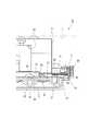
図5に照明器具10の垂直断面図を示し、図6に照明器具10の要部の断面図を示す。
図5に示すように、器具本体11は、垂直断面視コ字形状の側板13の内側に四角形の枠形状に形成された天板12が溶接等により接合されている。LED基板16は、天板12の下方に配置されており、複数のLED光源15が下方に向けて光軸を有して所定位置に実装されている。反射板部材17は、四角錐形状に配置された反射面26を有する複数の反射板18の外側に垂直方向に配置された立上板27を有する。反射板部材17は、複数の反射板18の上方頂部に上方開口部28を有し、上方開口部28がLED光源15に対応して配置される。反射板部材17は、ねじ29のねじ込みにより器具本体11の天板12の下面に取り付けられている。FIG. 5 shows a vertical cross-sectional view of the
As shown in FIG. 5, the instrument
図6に示すように、パネル19は、器具本体11の天板12の下方に配置された反射板部材17の立上板27を覆って配置されており、そのフランジ25が器具本体11の側板13に支持されている。点灯装置箱21は、ねじ30により器具本体11の側板13に取り付けられている。 As shown in FIG. 6, the
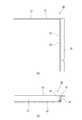
図7に照明器具10の要部の詳細を説明する拡大断面図を示す。
図7に示すように、パネル19は、反射板部材17の立上板27と間に第1隙間31を有する。第1隙間31は、反射板部材17の外側の4方に配置されており、反射板部材17とパネル19との嵌合および温度上昇に伴う膨張を考慮した大きさを有する。パネル19は、反射板部材17の立上板27の側部に配置される側板24の内面に第1光拡散部32を有する。第1光拡散部32は、パネル19の側板24の長手方向に沿って形成される。第1光拡散部32は、側板24の内面を粗く仕上げた粗面仕上面であり第1隙間31内に配置される。FIG. 7 shows an enlarged cross-sectional view illustrating details of a main part of the
As shown in FIG. 7, the
パネル19は、側板24の外面に第2光拡散部33を有する。第2光拡散部33は、パネル19の側板24の長手方向に沿って形成される。第2光拡散部33は、側板24の外面を粗く仕上げた粗面仕上面である。第1光拡散部32および第2光拡散部33は、LED光源15と反射板部材17の下方頂点34とを結ぶ接線35よりも外側に形成されている。そして、パネル19は、その底板22と反射板部材17の下方頂点34との間に第2隙間36を有する。第2隙間36は、LED光源15からの光のうち、パネル19の底板22において反射した反射光を側板24へ向ける。 The
なお、第1光拡散部32および第2光拡散部33は、粗く仕上げた粗面仕上面に代えて、シボ加工等でもよい。また、拡散させたい部分のみの材質を、拡散率の高い材料に変更して2色成形したり、あるいは、拡散させたい部分に拡散シート等の別部材を挟んだりしてもよい。 The first
図8に照明器具10の光学的な特性を説明する断面図を示す。
図7を含め、図8に示すように、照明器具10は、点灯装置20が駆動されることにより直流電源がLED基板16のプリント回路に供給されてLED光源15が発光される。LED光源15からの光は、パネル19の底板22を透過して床面に照射されるとともに反射板部材17の反射板18に有する反射面26により反射されてからパネル19の底板22を透過して床面に主に照射される。
そして、LED光源15からの光の一部は、パネル19の底板22の内面において反射されてから、第2隙間36を通じてパネル19の側板24へ向けて進行され、パネル19の側板24を透過して器具本体11の側方へ向けて進行されて天井施工面1を照射することになる。FIG. 8 is a cross-sectional view illustrating the optical characteristics of the
As shown in FIG. 8 including FIG. 7, in the
A part of the light from the LED
このとき、天井施工面1に照射される光は、点光源であるLED光源15の反射光および直接光ではなく、パネル19と反射板部材17との間の第1隙間31を介して第1光拡散部32および第2光拡散部33により拡散されて生成された拡散光であるために、輝度むらによる外観低下を防止して天井施工面1を広範囲に明るく照射する。
また、第1光拡散部32および第2光拡散部33が、LED光源15と反射板部材17の下方頂点34とを結ぶ接線35よりも外側に形成されていることにより、下方への照射光を拡散により低下させることなく側方への照射光を拡散できる。At this time, the light applied to the ceiling construction surface 1 is not reflected light or direct light of the
Further, the first
以上、説明した本発明に係る第1実施形態の照明器具10は、パネル19において反射板部材17の立上板27と間に第1隙間31を有し、パネル19において反射板部材17の立上板27の側部に配置される側板24の内面に第1光拡散部32を有する。
従って、本発明に係る第1実施形態の照明器具10は、LED光源15からの光の一部が、パネル19と反射板部材17の間の第1隙間31を介して第1光拡散部32により拡散された拡散光に生成されることにより天井施工面1を広範囲に明るく照射して空間の明るさ感を増加できる。As described above, the
Therefore, in the
また、本発明に係る第1実施形態の照明器具10は、パネル19において、その底板22と反射板部材17の下方頂点34との間に第2隙間36を有する。
従って、本発明に係る第1実施形態の照明器具10は、第2隙間36を通じて、LED光源15からの光のうち、パネル19の底板22において反射した反射光を側板24に効率良く向けることができる。Moreover, the
Therefore, the
そして、本発明に係る第1実施形態の照明器具10は、第1光拡散部32および第2光拡散部33が、LED光源15と反射板部材17の下方頂点34とを結ぶ接線35よりも外側に形成される。
従って、本発明に係る第1実施形態の照明器具10は、第1光拡散部32および第2光拡散部33により、下方への照射光を拡散により低下させることなく側方への照射光を効率良く拡散できる。And as for the
Therefore, the
(第2実施形態)
次に、本発明に係る第2実施形態の照明器具について説明する。なお、以下の各実施形態において、上述した第1実施形態と重複する構成要素や機能的に同様な構成要素については、図中に同一符号あるいは相当符号を付することによって説明を簡略化あるいは省略する。(Second Embodiment)
Next, the lighting fixture of 2nd Embodiment which concerns on this invention is demonstrated. In the following embodiments, components that are the same as those in the first embodiment described above or functionally similar components are simplified or omitted by giving the same reference numerals or equivalent symbols in the drawings. To do.
図9に本発明に係る第2実施形態の照明器具に適用されるパネルの斜め下方から視た外観斜視図を示す。
図9に示すように、本発明に係る第2実施形態の照明器具40に適用されるパネル41は、側板24の外面に第2光拡散部33を有するとともに端板23の外面に第3光拡散部42を有する。FIG. 9 shows an external perspective view of the panel applied to the lighting apparatus according to the second embodiment of the present invention as viewed obliquely from below.
As shown in FIG. 9, the
本発明に係る第2実施形態の照明器具40は、パネル41が、側板24の外面に第2光拡散部33を有するとともに端板23の外面に第3光拡散部42を有する。
従って、本発明に係る第2実施形態の照明器具40は、LED光源15からの光の一部が、第2光拡散部33および第3光拡散部42により拡散された拡散光に生成されることにより、照明器具40の長手方向を含めて天井施工面1を広範囲に明るく照射して空間の明るさ感を増加できる。In the
Therefore, in the
(第3実施形態)
次に、本発明に係る第3実施形態の照明器具について説明する。
図10(A)に本発明に係る第3実施形態の照明器具に適用されるパネルの水平断面図を示し、図10(B)に図10(A)の垂直断面図を示し、図11に本発明に係る第3実施形態の照明器具に適用されるパネル拡大断面図を示す。(Third embodiment)
Next, the lighting fixture of 3rd Embodiment which concerns on this invention is demonstrated.
FIG. 10 (A) shows a horizontal sectional view of a panel applied to the lighting apparatus of the third embodiment according to the present invention, FIG. 10 (B) shows a vertical sectional view of FIG. 10 (A), and FIG. The panel expanded sectional view applied to the lighting fixture of 3rd Embodiment which concerns on this invention is shown.
図10(A)および図10(B)に示すように、本発明に係る第3実施形態の照明器具50に適用されるパネル51は、側板24の長手方向に光拡散部に相当するプリズム状の凹凸面52を有する。
図11に示すように、プリズム状の凹凸面52は、例えば半球形状の凸部を連結して形成されている。As shown in FIGS. 10A and 10B, the
As shown in FIG. 11, the prism-shaped
本発明に係る第3実施形態の照明器具50は、パネル51が、側板24の長手方向に光拡散用のプリズム状の凹凸面52を有する。
従って、本発明に係る第3実施形態の照明器具50は、パネル51の凹凸面52が、例えば、やすり等を用いて粗面仕上面を粗く仕上げる場合と比べて、成形を簡単にできる。In the
Therefore, the
なお、本発明の照明器具において器具本体,LED光源,反射板等は前述した実施形態に限定されるものでなく、適宜な変形や改良等が可能である。 In the lighting fixture of the present invention, the fixture body, LED light source, reflector and the like are not limited to the above-described embodiments, and appropriate modifications and improvements can be made.
10,40,50 照明器具
15 LED光源
17 反射板部材(反射板)
18 反射板
19,41,51 パネル
27 立上板(立ち上がり面)
31 第1隙間(隙間)
32 第1光拡散部(光拡散部)
33 第2光拡散部(光拡散部)
34 下方頂点
35 接線
36 第2隙間(隙間)
42 第3光拡散部(光拡散部)
52 凹凸面(光拡散部)10, 40, 50
18
31 First gap (gap)
32 1st light diffusion part (light diffusion part)
33 Second light diffusion part (light diffusion part)
34
42 3rd light diffusion part (light diffusion part)
52 Uneven surface (light diffusion part)
Claims (3)
Translated fromJapanese外側に立ち上がり面を有する反射板と、
前記反射板の前面および外側面を覆うように配されたパネルとを備え、
前記反射板の前記立ち上がり面と前記パネルとの間に隙間を形成するとともに前記パネルの前記反射板の外側を覆う部分に光拡散部を形成した照明器具。A plurality of LED light sources;
A reflector having a rising surface on the outside;
A panel arranged to cover the front surface and the outer surface of the reflector,
The lighting fixture which formed the light-diffusion part in the part which covers the outer side of the said reflecting plate of the said panel while forming a clearance gap between the said standing surface of the said reflecting plate and the said panel.
前記反射板の頂点から外側面に至る部分に隙間を形成した照明器具。The lighting fixture according to claim 1,
The lighting fixture which formed the clearance gap in the part from the vertex of the said reflecting plate to an outer surface.
前記光拡散部は、前記LED光源と前記反射板の下方頂点とを結ぶ接線より外側に形成した照明器具。The lighting fixture according to claim 1 or 2,
The light diffusing unit is an illumination fixture formed outside a tangent line connecting the LED light source and a lower apex of the reflector.
Priority Applications (1)
| Application Number | Priority Date | Filing Date | Title |
|---|---|---|---|
| JP2010170526AJP5635325B2 (en) | 2010-07-29 | 2010-07-29 | lighting equipment |
Applications Claiming Priority (1)
| Application Number | Priority Date | Filing Date | Title |
|---|---|---|---|
| JP2010170526AJP5635325B2 (en) | 2010-07-29 | 2010-07-29 | lighting equipment |
Publications (2)
| Publication Number | Publication Date |
|---|---|
| JP2012033332Atrue JP2012033332A (en) | 2012-02-16 |
| JP5635325B2 JP5635325B2 (en) | 2014-12-03 |
Family
ID=45846542
Family Applications (1)
| Application Number | Title | Priority Date | Filing Date |
|---|---|---|---|
| JP2010170526AExpired - Fee RelatedJP5635325B2 (en) | 2010-07-29 | 2010-07-29 | lighting equipment |
Country Status (1)
| Country | Link |
|---|---|
| JP (1) | JP5635325B2 (en) |
Cited By (4)
| Publication number | Priority date | Publication date | Assignee | Title |
|---|---|---|---|---|
| JP2013069625A (en)* | 2011-09-26 | 2013-04-18 | Panasonic Corp | Lighting fixture |
| WO2014021706A1 (en)* | 2012-07-30 | 2014-02-06 | Silq (Malaysia) Sdn Bhd | Lighting device |
| JP2014032877A (en)* | 2012-08-03 | 2014-02-20 | Iris Ohyama Inc | Led lighting device |
| WO2017126574A1 (en)* | 2016-01-21 | 2017-07-27 | パナソニックIpマネジメント株式会社 | Ceiling fan |
Citations (6)
| Publication number | Priority date | Publication date | Assignee | Title |
|---|---|---|---|---|
| JP2003132708A (en)* | 2001-10-25 | 2003-05-09 | Tanabe Take Shoten:Kk | Led illumination device |
| JP2006202706A (en)* | 2005-01-24 | 2006-08-03 | Toshiba Lighting & Technology Corp | lighting equipment |
| WO2007037035A1 (en)* | 2005-09-28 | 2007-04-05 | The Furukawa Electric Co., Ltd. | Light box, light reflector for the same, and method for producing light reflector |
| JP2009037820A (en)* | 2007-08-01 | 2009-02-19 | Toshiba Home Lighting Kk | Lighting device and lighting fixture |
| JP2010123344A (en)* | 2008-11-18 | 2010-06-03 | Toshiba Lighting & Technology Corp | Luminaire |
| JP2010140797A (en)* | 2008-12-12 | 2010-06-24 | Toshiba Lighting & Technology Corp | Luminaire |
- 2010
- 2010-07-29JPJP2010170526Apatent/JP5635325B2/ennot_activeExpired - Fee Related
Patent Citations (6)
| Publication number | Priority date | Publication date | Assignee | Title |
|---|---|---|---|---|
| JP2003132708A (en)* | 2001-10-25 | 2003-05-09 | Tanabe Take Shoten:Kk | Led illumination device |
| JP2006202706A (en)* | 2005-01-24 | 2006-08-03 | Toshiba Lighting & Technology Corp | lighting equipment |
| WO2007037035A1 (en)* | 2005-09-28 | 2007-04-05 | The Furukawa Electric Co., Ltd. | Light box, light reflector for the same, and method for producing light reflector |
| JP2009037820A (en)* | 2007-08-01 | 2009-02-19 | Toshiba Home Lighting Kk | Lighting device and lighting fixture |
| JP2010123344A (en)* | 2008-11-18 | 2010-06-03 | Toshiba Lighting & Technology Corp | Luminaire |
| JP2010140797A (en)* | 2008-12-12 | 2010-06-24 | Toshiba Lighting & Technology Corp | Luminaire |
Cited By (4)
| Publication number | Priority date | Publication date | Assignee | Title |
|---|---|---|---|---|
| JP2013069625A (en)* | 2011-09-26 | 2013-04-18 | Panasonic Corp | Lighting fixture |
| WO2014021706A1 (en)* | 2012-07-30 | 2014-02-06 | Silq (Malaysia) Sdn Bhd | Lighting device |
| JP2014032877A (en)* | 2012-08-03 | 2014-02-20 | Iris Ohyama Inc | Led lighting device |
| WO2017126574A1 (en)* | 2016-01-21 | 2017-07-27 | パナソニックIpマネジメント株式会社 | Ceiling fan |
Also Published As
| Publication number | Publication date |
|---|---|
| JP5635325B2 (en) | 2014-12-03 |
Similar Documents
| Publication | Publication Date | Title |
|---|---|---|
| US7841738B2 (en) | Luminaire having light emitting diodes (leds) directed to a reflector | |
| WO2013133147A1 (en) | Illuminating apparatus | |
| JP5348778B2 (en) | lighting equipment | |
| JP5635325B2 (en) | lighting equipment | |
| JP5366298B2 (en) | lighting equipment | |
| CN102822082A (en) | Lighting device for elevator car | |
| JP2016189285A (en) | Light source unit and lighting apparatus using the same | |
| JP5732613B2 (en) | lighting equipment | |
| JP2010123344A (en) | Luminaire | |
| JP5241018B2 (en) | lighting equipment | |
| JP2010146806A (en) | lighting equipment | |
| JP2015222692A (en) | Lighting fixture | |
| JP6226183B2 (en) | lighting equipment | |
| JP5364042B2 (en) | lighting equipment | |
| JP2014127380A (en) | Illumination device | |
| CN102606967B (en) | Irradiate utensil | |
| KR20110011847A (en) | Panel-integrated lighting without glare | |
| JP6547955B2 (en) | lighting equipment | |
| JP5677538B2 (en) | lighting equipment | |
| JP5348777B2 (en) | lighting equipment | |
| KR102802587B1 (en) | Ceiling luminaire with improved light distribution efficiency | |
| JP7122631B2 (en) | lighting equipment | |
| JP3192795U (en) | LED lighting device | |
| JP2011171226A (en) | Luminaire | |
| KR100993016B1 (en) | Learning light control LED lighting stand |
Legal Events
| Date | Code | Title | Description |
|---|---|---|---|
| A711 | Notification of change in applicant | Free format text:JAPANESE INTERMEDIATE CODE: A712 Effective date:20120116 | |
| A621 | Written request for application examination | Free format text:JAPANESE INTERMEDIATE CODE: A621 Effective date:20130611 | |
| RD04 | Notification of resignation of power of attorney | Free format text:JAPANESE INTERMEDIATE CODE: A7424 Effective date:20131225 | |
| A977 | Report on retrieval | Free format text:JAPANESE INTERMEDIATE CODE: A971007 Effective date:20140522 | |
| A131 | Notification of reasons for refusal | Free format text:JAPANESE INTERMEDIATE CODE: A131 Effective date:20140527 | |
| A521 | Request for written amendment filed | Free format text:JAPANESE INTERMEDIATE CODE: A523 Effective date:20140724 | |
| TRDD | Decision of grant or rejection written | ||
| A01 | Written decision to grant a patent or to grant a registration (utility model) | Free format text:JAPANESE INTERMEDIATE CODE: A01 Effective date:20140916 | |
| A61 | First payment of annual fees (during grant procedure) | Free format text:JAPANESE INTERMEDIATE CODE: A61 Effective date:20141016 | |
| R151 | Written notification of patent or utility model registration | Ref document number:5635325 Country of ref document:JP Free format text:JAPANESE INTERMEDIATE CODE: R151 | |
| LAPS | Cancellation because of no payment of annual fees |