JP2012032058A - Humidifier - Google Patents
HumidifierDownload PDFInfo
- Publication number
- JP2012032058A JP2012032058AJP2010170759AJP2010170759AJP2012032058AJP 2012032058 AJP2012032058 AJP 2012032058AJP 2010170759 AJP2010170759 AJP 2010170759AJP 2010170759 AJP2010170759 AJP 2010170759AJP 2012032058 AJP2012032058 AJP 2012032058A
- Authority
- JP
- Japan
- Prior art keywords
- air
- water
- filter
- vaporization filter
- turbine unit
- Prior art date
- Legal status (The legal status is an assumption and is not a legal conclusion. Google has not performed a legal analysis and makes no representation as to the accuracy of the status listed.)
- Granted
Links
Images


Landscapes
- Air Humidification (AREA)
Abstract
Translated fromJapaneseDescription
Translated fromJapanese本発明は、水を含んだ気化フィルタに空気を通すことで、この空気に湿度を与える加湿装置に関し、詳細には、気化フィルタに通風する構造に関する。 The present invention relates to a humidifying device that gives humidity to air by passing air through a vaporization filter containing water, and more particularly, to a structure that ventilates the vaporization filter.
従来の気化式の加湿装置においては、空気の吸込口と吹出口とを有し、吸込口と吹出口とを結ぶ空気通路を内部に有する筐体を備え、この空気通路内には、吸込口から空気を吸込み、この吸込んだ空気を空気通路を経て吹出口から吹出させる送風機が配置されている。 In a conventional vaporizing humidifier, an air suction port and an air outlet are provided, and a housing having an air passage that connects the air inlet and the air outlet is provided inside the air passage. A blower is arranged to suck in air from the air and blow out the sucked air through the air passage from the outlet.
送風機と吸込口との間の空気通路内には、給水タンクから供給された水を貯える給水トレイと、この給水トレイの上部側に配置され、給水トレイに貯えられた水を吸水して湿潤した状態で通過する空気に湿度を与える気化フィルタが配置されている。 In the air passage between the blower and the suction port, a water supply tray for storing water supplied from the water supply tank and an upper side of the water supply tray are disposed, and the water stored in the water supply tray is absorbed to be wet. A vaporizing filter that provides humidity to the air passing in the state is arranged.
この加湿装置は、加湿運転時、送風機の回転により、吸込口から吸込んだ空気を湿潤した状態の気化フィルタに通すことで、吸込んだ空気を加湿して吹出口から吹き出すようになっている。 During the humidifying operation, the humidifier is configured to pass the air sucked from the suction port through a moistened vaporization filter by the rotation of the blower, so that the sucked air is humidified and blown out from the outlet.
このような加湿装置としては、円板形状の気化フィルタを取付けた枠体に水汲みポケットを備え、枠体とともに気化フィルタを回転させることにより、給水トレイの水を水汲みポケットで汲み上げて気化フィルタに吸水させるものが提案されている(例えば、特許文献1参照)。 As such a humidifying device, a water pumping pocket is provided in a frame body to which a disk-shaped vaporizing filter is attached, and by rotating the vaporizing filter together with the frame body, water in the water supply tray is pumped up by the water pumping pocket, and the vaporizing filter is used. The thing which makes it absorb water is proposed (for example, refer patent document 1).
この特許文献1の加湿装置では、枠体を回転自在に保持するために、給水トレイの上部側に枠体保持部が取付けられ、この枠体保持部の上端に有する軸受部により、枠体の中心に有する回転軸が軸支される構造になっている。 In the humidifying device of this Patent Document 1, in order to hold the frame body in a rotatable manner, a frame body holding part is attached to the upper side of the water supply tray, and the bearing of the frame body holding part has an upper end of the frame body holding part. A rotation shaft at the center is supported.
しかしながら、特許文献1では、枠体保持部は給水トレイから立設し、気化フィルタに対向するように配置されているため、この枠体保持部が気化フィルタに対する空気の通風の妨げになってしまう。したがって、気化フィルタの全面のうち、枠体保持部に対向する気化フィルタの一部分に空気が通らず、気化フィルタを有効利用することができなかった。 However, in Patent Document 1, since the frame body holding portion is erected from the water supply tray and is disposed so as to face the vaporization filter, the frame body holding portion hinders the ventilation of air to the vaporization filter. . Therefore, air does not pass through a part of the vaporization filter facing the frame body holding portion of the entire vaporization filter, and the vaporization filter cannot be effectively used.
特許文献1では、気化フィルタを通過する空気の風速と気化フィルタの面積とが不変と考えた場合、気化フィルタには空気が通らない不通過面が存在するため、この不通過面に相当する分だけ、気化フィルタの利用面積が実質的に小さくなっている。このため、風速と面積の積で表わされる気化フィルタを通過する通過風量が実質的に小さくなり、加湿量を十分に確保することができないという問題点があった。 In Patent Document 1, when it is considered that the wind speed of the air passing through the vaporizing filter and the area of the vaporizing filter are unchanged, the vaporizing filter has a non-passing surface through which air does not pass. Only the use area of the vaporization filter is substantially reduced. For this reason, there has been a problem that the amount of passing air passing through the vaporization filter represented by the product of the wind speed and the area is substantially reduced, and a sufficient amount of humidification cannot be ensured.
本発明は上記問題点に鑑み、気化フィルタの加湿に寄与する利用面を大きくし、気化フィルタの有効利用を図ることができる加湿装置を提供することを目的とする。 In view of the above problems, an object of the present invention is to provide a humidifier capable of increasing the utilization surface that contributes to humidification of a vaporization filter and effectively using the vaporization filter.
本発明は上記課題を解決するため、請求項1記載の発明は、空気の吸込口と吹出口とを有し前記吸込口と前記吹出口とを結ぶ空気通路を内部に有する筐体と、前記吸込口から空気を吸込み該吸込んだ空気を前記空気通路を経て吹出口から吹出させる送風機と、同送風機と前記吸込口との間の前記空気通路内に設けられ水を吸水して湿潤した状態で通過する空気に湿度を与える気化フィルタと、同気化フィルタの下部側に配置され、前記気化フィルタに給水するための水を貯える給水トレイと、前記気化フィルタを収容する収容部と、同収容部の外周側に前記給水トレイの水を汲み上げて前記気化フィルタに吸水させる水汲みポケットとを有する水車ユニットと、前記給水トレイから立設され前記水車ユニットを回転可能に保持する一対の水車ユニット保持部とを備えた加湿装置であって、前記一対の水車ユニット保持部に前記空気通路を流れる空気の一部を通過させる通風孔を設けたことを特徴とする。 In order to solve the above-mentioned problems, the invention according to claim 1 includes a housing having an air inlet and an air outlet, and an air passage connecting the air inlet and the air outlet, A blower that sucks air from the suction port and blows out the sucked air from the blowout port through the air passage, and is provided in the air passage between the blower and the suction port to absorb and wet the water. A vaporizing filter that gives humidity to the passing air; a water supply tray that is disposed on the lower side of the vaporizing filter and stores water for supplying water to the vaporizing filter; a housing unit that houses the vaporizing filter; and A water turbine unit having a water pump pocket for pumping up water from the water supply tray on the outer peripheral side and absorbing the water into the vaporizing filter, and a pair of water turbines standing from the water supply tray and rotatably holding the water turbine unit A humidifier comprising a knit holding portion, characterized in that a ventilating hole for passing a part of the air flowing through the air passage to the pair of hydraulic turbine unit support.
請求項2記載の発明は、請求項1記載の加湿装置において、前記通風孔は縦桟及び/又は横桟で区切られた複数個の孔からなることを特徴とする。 According to a second aspect of the present invention, in the humidifying device according to the first aspect, the ventilation hole is composed of a plurality of holes divided by a vertical beam and / or a horizontal beam.
請求項3記載の発明は、請求項1または請求項2記載の加湿装置において、前記水車ユニットの中心に円筒状の一対の回転軸を備えるとともに前記水車ユニット保持部の上端に前記回転軸を回転自在に保持する軸受部を備え、同軸受部に前記空気通路を流れる空気の一部を通過させる貫通孔を設けたことを特徴とする。 According to a third aspect of the present invention, in the humidifying device according to the first or second aspect, a pair of cylindrical rotation shafts are provided at the center of the water turbine unit, and the rotation shaft is rotated at the upper end of the water turbine unit holding portion. A bearing portion that is freely held is provided, and a through hole that allows a part of the air flowing through the air passage to pass therethrough is provided in the bearing portion.
請求項1記載の本発明によれば、加湿装置において、一対の水車ユニット保持部に空気通路を流れる空気の一部を通過させる通風孔を設けたことにより、空気の加湿に寄与する気化フィルタの利用面積が増え、気化フィルタの有効利用を図ることができる。 According to the first aspect of the present invention, in the humidifier, the ventilation filter that contributes to humidification of the air is provided by providing the pair of water turbine unit holding portions with the ventilation holes that allow a part of the air flowing through the air passage to pass therethrough. The use area increases and the vaporization filter can be used effectively.
請求項2記載の本発明によれば、通風孔を縦桟と横桟で区切られた複数の孔にしたことにより、水車ユニット保持部の強度を確保することができる。 According to the second aspect of the present invention, the strength of the water turbine unit holding portion can be ensured by making the ventilation holes into a plurality of holes divided by the vertical beam and the horizontal beam.
請求項3記載の本発明によれば、水車ユニットの中心に円筒状の一対の回転軸を備えるとともに水車ユニット保持部の上端に回転軸を回転自在に保持する軸受部を備え、軸受部に空気通路を流れる空気の一部を通過させる貫通孔を設けたことにより、空気の加湿に寄与する気化フィルタの利用面積が更に増えて、気化フィルタの有効利用を図ることができる。 According to the third aspect of the present invention, the water turbine unit is provided with a pair of cylindrical rotating shafts at the center and a bearing portion that rotatably holds the rotating shaft at the upper end of the water turbine unit holding portion. By providing the through hole through which a part of the air flowing through the passage is passed, the use area of the vaporization filter that contributes to humidification of the air is further increased, and the vaporization filter can be effectively used.
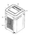
以下、本発明の実施形態を添付図面に基づき詳細に説明する。図1および図2に示すように、本実施形態における加湿装置は、気化式の加湿装置であり、その筐体10が縦長の略直方体形状で構成されている。筐体10は、面積の最も大きい一方の側面に前面パネル32が形成され、この前面パネル32と対向する他方の側面に背面パネル34が形成されている。背面パネル34には、多数の開口部を設けた空気の吸込口26が形成されている。 Embodiments of the present invention will be described below in detail with reference to the accompanying drawings. As shown in FIG. 1 and FIG. 2, the humidifier in the present embodiment is a vaporizing humidifier, and the
筐体10の上面には、操作パネル44と、この操作パネル44と隣接する矩形状のルーバ30とが配置されている。操作パネル44には、ユーザが加湿装置を運転操作するための各種ボタンや表示ランプなどが配されている。ルーバ30は、手動により開閉可能になっており、後述する空気の吹出口28となる。 An
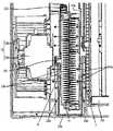
次に、筐体10の内部の構成を説明する。図3乃至図6に示すように、筐体10の内部には、吸込口26と吹出口28とを結ぶ空気通路が設けられている。この空気通路の上流側から下流側に向かって、プレフィルタ50、集塵フィルタ52、ヒータ脱臭ユニット54、気化フィルタ14、送風機12、オゾン発生ユニット16、マイナスイオン発生器46が順に配置されている。 Next, the internal configuration of the
プレフィルタ50は、大きな埃やペットの毛などを捕集するフィルタであり、集塵フィルタ52は、小さな塵や花粉などを捕集するプリーツ構造のフィルタである。ヒータ脱臭ユニット54は、ヒータと脱臭フィルタとを備え、ヒータにより脱臭フィルタを加熱して、脱臭フィルタに付着した油の臭い、タバコやペットの臭いなどの悪臭成分を分解して除去するユニットである。 The
気化フィルタ14は、通気性と吸水性を備えるプリーツ構造のフィルタであり、ポリエステルとレーヨンが50:50の割合で配合されたフィルタである。気化フィルタ14は、水を吸水して湿潤した状態で空気が通過する間に、水が気化して空気に湿度を与える。なお、気化フィルタ14の材質の種類や配合の割合は、これに限定することなく、適宜選択することができる。 The
送風機12は、ファンモータ12aと、このファンモータ12aにより駆動されるファン12bとにより構成され、ファン12bを回転させることにより、吸込口26から空気を吸込み(白抜き矢印A)、この吸込んだ空気を空気通路を経て吹出口28から吹出す(白抜き矢印E、F)ものである。 The
オゾン発生ユニット16は、送風機12の下流側から上方に延びる空気通路の上部に設けられ、オゾン発生ユニット16内の上流側から下流側に向かって、吸込口161、オゾン発生部16a、オゾン分解触媒58、低濃度オゾン吹出口162が順に配置されている。 The
オゾン発生部16aは、水銀ランプなどのUVランプであり、UVランプの紫外線でオゾンを発生する。オゾン分解触媒58は、オゾン発生ユニット16内で発生したオゾンを低濃度オゾン吹出口162から吹出す際に、オゾン濃度を適正な範囲にするため、酸化チタンなどの金属触媒の作用によって、オゾンを分解する。 The
オゾン発生ユニット16には、オゾン発生部16aよりも下流側でオゾン分解触媒58よりも上流側に、気化フィルタ14の風上面に向かって連通するオゾンダクト18が取付けられている。オゾンダクト18の先端には、気化フィルタ14の風上面にオゾン発生部16aで発生したオゾンを吹付ける吹付口18aが形成されている。吹付口18aから吹き付けられるオゾンにより、気化フィルタ14は除菌されるため、気化フィルタ14を清潔に保つことができる。 The
マイナスイオン発生器46は、吹出口28付近の空気通路に配置され、放電電極と接地電極とを備えている。マイナスイオン発生器46は、直流高圧電源により放電電極と接地電極との間に、例えば、数kVの高電圧が印加されると、放電電極と接地電極との間にコロナ放電が起こり、コロナ放電で放出された電子が空気中の原子や分子と結合してマイナスイオンを発生する。 The
筐体10内にはその他に、メイン基板40がプレフィルタ50および集塵フィルタ52の上部に配置され、加湿装置の動作を制御する制御部を備えている。制御部は、ユーザによる操作パネル44の各種ボタンの押下で決まる運転指示を受けて運転制御を行う。 In addition, a
メイン基板40の制御部では、送風機12のファンモータ12aや後述する気化フィルタ14を回転するフィルタ回転モータ22aの駆動、オゾン発生ユニット16のUVランプ16aの点灯、マイナスイオン発生器46の電源オンオフなどの運転制御を行う。 In the control unit of the
次に、以上説明してきた加湿装置の基本動作を説明する。加湿装置の加湿運転時、吸込口26から吸込まれた空気(白抜き矢印A)は、プレフィルタ50、集塵フィルタ52およびヒータ脱臭ユニット54を通過する間に除塵および脱臭される。次いで、除塵および脱臭された空気は、気化フィルタ14を通過する間に、湿潤した状態の気化フィルタ14から水が気化して加湿される。 Next, the basic operation of the humidifier described above will be described. During the humidifying operation of the humidifier, the air (white arrow A) sucked from the
加湿された空気は、送風機12のファン12b内に吸引され、ファン12bの下流側から上方に延びる空気通路に送り出される(白抜き矢印B)。次いで、空気通路に送り出された空気は、ルーバ30を開けた状態で吹出口28から吹出される(白抜き矢印E)。 The humidified air is sucked into the
マイナスイオン発生器46で発生したマイナスイオンは、吹出口28から吹出される空気(白抜き矢印E)に乗って放出される。放出されたマイナスイオンは、加湿装置の外部の空気中に浮遊するカビやウイルスなどの微生物に付着してこれらを不活性化する。 The negative ions generated by the
加湿された空気の一部は、オゾン発生ユニット16内に吸込口161より取り込まれ(白抜き矢印C)、オゾン発生部16aによりオゾンが生成される。生成されたオゾンは、オゾン分解触媒58により余分なオゾンが分解される。余分なオゾンが分解されて低濃度(0.02ppm以下)になったオゾンは、低濃度オゾン吹出口162を通って(白抜き矢印F)、吹出口28から吹出される。 Part of the humidified air is taken into the
一方、オゾン発生部16aで発生したオゾンの一部は、気化フィルタ14の風上面付近が負圧に、オゾン発生ユニット16付近が正圧になるため、この圧力差の作用によって、オゾンダクト18内に誘引され、吹付口18aから気化フィルタ14の風上面に吹付けられる(矢印D)。 On the other hand, a part of the ozone generated in the
気化フィルタ14に吹付けられたオゾンは、吸込口26から吸込んだ空気とともに気化フィルタ14を通過する間に気化フィルタ14の除菌や消臭を行う。これにより、気化フィルタ14は常に清潔な状態で保たれる。 The ozone sprayed on the
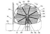
次に、気化フィルタ14の周辺の構成を説明する。図4乃至図10に示すように、空気通路内には、気化フィルタ14が収容された水車ユニット15を備えている。水車ユニット15は水汲みカバー15aと歯車カバー15gを備えており、円盤状の水汲みカバー15aと歯車カバー15gを互いに嵌合することで、水車ユニット15の内部に円盤状の空間(気化フィルタ14を収容する気化フィルタ収容部)を形成する。なお、気化フィルタ収容部は、後述する水汲みカバー15aおよび歯車カバー15gに設けられる一対の収容部15f、15mにて構成されている。 Next, the configuration around the
水汲みカバー15aは、輪状枠15bと回転軸15cとアーム部15dとを備えている。輪状枠15bの外周側には、円周方向に等間隔で複数の水汲みポケット15eが設けられ、輪状枠15bの内周側には、気化フィルタ14を収容する収容部15fが設けられている。回転軸15cは、空気の通過方向(白抜き矢印A)に円筒状に形成されており、空気の通過方向に直交する方向に放射状に延びる複数のアーム部15dを介して輪状枠15bと連結されている。複数のアーム部15d同士の間は開放されており、気化フィルタ14が露出されて空気が通過可能になっている。 The
歯車カバー15gは、輪状枠15hと回転軸15iとアーム部15jとを備えている。輪状枠15hの外周側には、円周方向に一体形成された従動歯車15kが設けられ、輪状枠15hの内周側には、気化フィルタ14を収容する収容部15mが設けられている。回転軸15iは、空気の通過方向(白抜き矢印A)に円筒状に形成されており、空気の通過方向に直交する方向に放射状に延びる複数のアーム部15jを介して輪状枠15hと連結されている。複数のアーム部15j同士の間は開放されており、気化フィルタ14が露出されて空気が通過可能になっている。 The
水車ユニット15は、従動歯車15kがフィルタ回転モータ22の出力軸に連結された駆動歯車22aと噛み合っており、シンクロナスモータなどのフィルタ回転モータ22を駆動することにより、回転軸15cおよび回転軸15iに直交する方向(矢印G)に、気化フィルタ14とともに一定速度で回転可能になっている。 In the
また、空気通路内には、水車ユニット15(気化フィルタ14)の下部側に、気化フィルタ14に給水するための水を供給する給水ユニット24を備えている。給水ユニット24は、給水トレイ24aと給水タンク保持部24bと仕切り板24cと一対の水車ユニット保持部24dとを備えている。 Further, in the air passage, a
給水トレイ24aは、図示しない給水タンクから供給された水を貯えるものであり、貫通孔24b1を介して給水タンク保持部24bと連通されている。給水タンク保持部24bは、給水タンクを保持する保持部であり、給水トレイ24aの水が一定の水位以下になると、給水タンクからの水を給水トレイ24aに貫通孔24b1を介して供給する。仕切り板24cは、水車ユニット15と給水タンクとの間を仕切るものである。 The
一対の水車ユニット保持部24dは、給水トレイ24aの長手方向の両側面中央からそれぞれ立設され、水車ユニット15を回転自在に保持するものである。一対の水車ユニット保持部24dの上端は軸受部24hをそれぞれ備え、これらの軸受部24hに水車ユニット15の回転軸15cおよび回転軸15hが軸支されている。 The pair of water turbine
これにより、一対の水車ユニット保持部24dは、空気の通過方向(白抜き矢印A)に直交する気化フィルタ14の風上面および風下面にそれぞれ対向するように配置される。なお、一対の水車ユニット保持部24dは、給水トレイ24aに一定の水位の水が貯まった状態において、気化フィルタ14に直に吸水されない高さで、水汲みポケット15eで水汲み可能な高さに立設されている。 Thereby, a pair of water turbine unit holding |
一対の水車ユニット保持部24dは、空気通路を流れる空気の一部を通過させる通風孔24eをそれぞれ備えている。これらの通風孔24eは、縦桟24fと横桟24gで区切られた略矩形状の複数の孔からなっている。このように、水車ユニット保持部24dに通風孔24eを備えていても、縦桟24fが横桟24gで連結された構造になっているため、水車ユニット保持部24dの強度を確保することができる。なお、水車ユニット保持部24dは、本実施例では給水トレイ24aに一体形成しているが、給水トレイ24aとは別部材であってもよい。 Each of the pair of water turbine
次に、加湿装置の加湿運転時、気化フィルタ14を湿潤させる動作を説明する。図8乃至図10に示すように、フィルタ回転モータ22が駆動されると、水車ユニット15は矢印Gの方向に回転し、給水トレイ24a内に貯まった水を水汲みポケット15eで汲み上げる。水車ユニット15の回転により、水汲みポケット15eが頂上付近に到達すると、汲み上げられた水が気化フィルタ14に掛かって吸水される。 Next, the operation of wetting the vaporizing
空になった水汲みポケット24は、水車ユニット15が一回転する毎に、給水トレイ24a内に貯まった水を繰返し汲み上げる。水車ユニット15が回転しているときは、複数の水汲みポケット15eによって汲み上げられた水が、気化フィルタ14に順次掛かって吸水されるため、気化フィルタ14の全面を湿潤な状態に保持する。 The empty
次に、加湿装置の加湿運転時、気化フィルタ14による加湿動作を説明する。図11に示すように、 湿潤な状態に保持された気化フィルタ14を、ヒータ脱臭ユニット54で除塵および脱臭された空気が通過する際、気化フィルタ14に含まれる水が気化して通過空気が加湿される。 Next, the humidifying operation by the
このとき、除塵および脱臭された空気は、図8に示す複数のアーム部15d同士の間を通過するとともに、風上側の水車ユニット保持部24dに備えた通風孔24eを通過する(矢印J)。次いで、気化フィルタ14を通過し、加湿された空気として、図9に示す複数のアーム部15j同士の間を通過するとともに、風下側の水車ユニット保持部24dに備えた通風孔24eを通過する(矢印K)。 At this time, the dust-removed and deodorized air passes between the
この結果、本実施形態による加湿装置においては、気化フィルタ14の全面のうち、風上側の水車ユニット保持部24dに対向する気化フィルタ14の一部分にも、通風孔24eを介して除塵および脱臭された空気の一部が通過することになるので、気化フィルタ14を有効利用することができる。 As a result, in the humidifier according to the present embodiment, dust and deodorization of the entire surface of the
具体的には、風上側の水車ユニット保持部24dが気化フィルタ14に対する通風の妨げにならず、空気の加湿に寄与する気化フィルタ14の利用面積が増えるため、気化フィルタ14を通過する通過風量を大きくすることができ、気化フィルタ14での加湿量を十分に確保することができる。 More specifically, the wind turbine
また、風下側の水車ユニット保持部24dが気化フィルタ14で加湿された空気に対する通風の妨げにならないため、空気のよりスムーズな流れを形成して吹出口28から加湿された空気を吹出すことができる。 Further, since the leeward water turbine
次に、図12を用いて、一対の水車ユニット保持部24dのその他の実施例を説明する。なお、これまでに説明した本実施形態による加湿装置とは、一対の水車ユニット保持部24dの上端に備える軸受部24hの構造が相違するのみであるため、その他の構成については説明を省略する。 Next, another embodiment of the pair of water turbine
図12に示すように、風上側の水車ユニット保持部24dには、軸受部24hの中心を貫通させて、空気通路を流れる空気の一部を通過させる貫通孔24iを備えている。図示しない風下側の水車ユニット保持部24dにも同様に、軸受部24hの中心を貫通させて、空気通路を流れる空気の一部を通過させる貫通する貫通孔24iを備えている。 As shown in FIG. 12, the wind turbine
除塵および脱臭された空気の一部は、風上側の水車ユニット保持部24dに備えた貫通孔24iを通過し、次いで、円筒状の回転軸15cを介して気化フィルタ14を通過し、加湿された空気として、円筒状の回転軸15iを介して風下側の水車ユニット保持部24dに備えた貫通孔24iを通過する。この結果、本実施形態による加湿装置においては、空気の加湿に寄与する気化フィルタ14の利用面積を更に増やすことができ、気化フィルタ14を通過する通過風量をより大きくすることができる。 Part of the dedusted and deodorized air passes through the through hole 24i provided in the wind turbine
10 筐体
12 送風機
12a ファンモータ
12b ファン
14 気化フィルタ
15 水車ユニット
15a 水汲みカバー
15b 輪状枠
15c 回転軸
15d アーム部
15e 水汲みポケット
15f 収容部
15g 歯車カバー
15h 輪状枠
15i 回転軸
15j アーム部
15k 従動歯車
15m 収容部
16 オゾン発生ユニット
161 吸込口
162 低濃度オゾン吹出口
16a UVランプ
18 オゾンダクト
18a オゾン吹付口
22 フィルタ回転モータ
22a 駆動歯車
24 給水ユニット
24a 給水トレイ
24b 給水タンク保持部
24b1 貫通孔
24c 仕切り板
24d 水車ユニット保持部
24e 通風孔
24f 縦桟
24g 横桟
24h 軸受部
24i 貫通孔
26 吸込口
28 吹出口
30 ルーバ
32 前面パネル
34 背面パネル
36 分解オゾン吹出口
40 メイン基板
44 操作パネル
50 プレフィルタ
52 集塵フィルタ
54 ヒータ脱臭ユニット
58 オゾン分解触媒DESCRIPTION OF
Claims (3)
Translated fromJapanese前記吸込口から空気を吸込み該吸込んだ空気を前記空気通路を経て吹出口から吹出させる送風機と、
同送風機と前記吸込口との間の前記空気通路内に設けられ水を吸水して湿潤した状態で通過する空気に湿度を与える気化フィルタと、
同気化フィルタの下部側に配置され、前記気化フィルタに給水するための水を貯える給水トレイと、
前記気化フィルタを収容する収容部と、同収容部の外周側に前記給水トレイの水を汲み上げて前記気化フィルタに吸水させる水汲みポケットとを有する水車ユニットと、
前記給水トレイから立設され前記水車ユニットを回転可能に保持する一対の水車ユニット保持部とを備えた加湿装置であって、
前記一対の水車ユニット保持部に前記空気通路を流れる空気の一部を通過させる通風孔を設けたことを特徴とする加湿装置。A housing having an air inlet and an air outlet and having an air passage connecting the air inlet and the air outlet inside;
A blower that sucks air from the suction port and blows out the sucked air from the outlet through the air passage;
A vaporizing filter that is provided in the air passage between the air blower and the suction port and absorbs water to give humidity to air passing in a wet state;
A water supply tray which is disposed on the lower side of the vaporization filter and stores water for supplying water to the vaporization filter;
A water turbine unit having a housing portion for housing the vaporizing filter, and a water pumping pocket for pumping water from the water supply tray to be absorbed by the vaporizing filter on an outer peripheral side of the housing portion;
A humidifying device comprising a pair of water turbine unit holding portions that are erected from the water supply tray and rotatably hold the water wheel unit,
A humidifying device, wherein the pair of water turbine unit holding portions are provided with ventilation holes for allowing a part of the air flowing through the air passage to pass therethrough.
同軸受部に前記空気通路を流れる空気の一部を通過させる貫通孔を設けたことを特徴とする請求項1または請求項2記載の加湿装置。A pair of cylindrical rotary shafts at the center of the water turbine unit, and a bearing portion that rotatably holds the rotary shaft at the upper end of the water turbine unit holding portion;
The humidifying device according to claim 1 or 2, wherein a through hole through which a part of the air flowing through the air passage is passed is provided in the bearing portion.
Priority Applications (1)
| Application Number | Priority Date | Filing Date | Title |
|---|---|---|---|
| JP2010170759AJP5408066B2 (en) | 2010-07-29 | 2010-07-29 | Humidifier |
Applications Claiming Priority (1)
| Application Number | Priority Date | Filing Date | Title |
|---|---|---|---|
| JP2010170759AJP5408066B2 (en) | 2010-07-29 | 2010-07-29 | Humidifier |
Related Child Applications (2)
| Application Number | Title | Priority Date | Filing Date |
|---|---|---|---|
| JP2013227419ADivisionJP5708758B2 (en) | 2013-10-31 | 2013-10-31 | Humidifier |
| JP2013226390ADivisionJP5812080B2 (en) | 2013-10-31 | 2013-10-31 | Humidifier |
Publications (2)
| Publication Number | Publication Date |
|---|---|
| JP2012032058Atrue JP2012032058A (en) | 2012-02-16 |
| JP5408066B2 JP5408066B2 (en) | 2014-02-05 |
Family
ID=45845689
Family Applications (1)
| Application Number | Title | Priority Date | Filing Date |
|---|---|---|---|
| JP2010170759AExpired - Fee RelatedJP5408066B2 (en) | 2010-07-29 | 2010-07-29 | Humidifier |
Country Status (1)
| Country | Link |
|---|---|
| JP (1) | JP5408066B2 (en) |
Cited By (9)
| Publication number | Priority date | Publication date | Assignee | Title |
|---|---|---|---|---|
| JP2014020624A (en)* | 2012-07-13 | 2014-02-03 | Daikin Ind Ltd | Humidifier |
| JP2014020620A (en)* | 2012-07-13 | 2014-02-03 | Daikin Ind Ltd | Humidifier |
| KR20140078939A (en)* | 2012-12-18 | 2014-06-26 | 삼성전자주식회사 | Evaporative Humidifier |
| JP2014142128A (en)* | 2013-01-24 | 2014-08-07 | Panasonic Corp | Humidifier and air cleaner with humidification function |
| WO2014162799A1 (en)* | 2013-04-02 | 2014-10-09 | シャープ株式会社 | Humidification device |
| KR20170046327A (en)* | 2015-10-21 | 2017-05-02 | 코웨이 주식회사 | Rotating humidification filter and humidification apparatus |
| CN102679519B (en)* | 2012-06-18 | 2017-10-10 | 海尔集团公司 | A kind of humidification water wheel and air purification humidifier |
| JP2020159597A (en)* | 2019-03-26 | 2020-10-01 | パナソニックIpマネジメント株式会社 | Humidifier |
| JP2020159661A (en)* | 2019-03-28 | 2020-10-01 | パナソニックIpマネジメント株式会社 | Humidifier |
Citations (3)
| Publication number | Priority date | Publication date | Assignee | Title |
|---|---|---|---|---|
| JPS5569643U (en)* | 1978-11-07 | 1980-05-13 | ||
| JP2004232941A (en)* | 2003-01-30 | 2004-08-19 | Hitachi Hometec Ltd | humidifier |
| JP2009121752A (en)* | 2007-11-15 | 2009-06-04 | Panasonic Corp | Humidifier |
- 2010
- 2010-07-29JPJP2010170759Apatent/JP5408066B2/ennot_activeExpired - Fee Related
Patent Citations (3)
| Publication number | Priority date | Publication date | Assignee | Title |
|---|---|---|---|---|
| JPS5569643U (en)* | 1978-11-07 | 1980-05-13 | ||
| JP2004232941A (en)* | 2003-01-30 | 2004-08-19 | Hitachi Hometec Ltd | humidifier |
| JP2009121752A (en)* | 2007-11-15 | 2009-06-04 | Panasonic Corp | Humidifier |
Cited By (15)
| Publication number | Priority date | Publication date | Assignee | Title |
|---|---|---|---|---|
| CN102679519B (en)* | 2012-06-18 | 2017-10-10 | 海尔集团公司 | A kind of humidification water wheel and air purification humidifier |
| JP2014020620A (en)* | 2012-07-13 | 2014-02-03 | Daikin Ind Ltd | Humidifier |
| JP2014020624A (en)* | 2012-07-13 | 2014-02-03 | Daikin Ind Ltd | Humidifier |
| KR20140078939A (en)* | 2012-12-18 | 2014-06-26 | 삼성전자주식회사 | Evaporative Humidifier |
| KR102054686B1 (en)* | 2012-12-18 | 2019-12-11 | 삼성전자주식회사 | Evaporative Humidifier |
| JP2014142128A (en)* | 2013-01-24 | 2014-08-07 | Panasonic Corp | Humidifier and air cleaner with humidification function |
| CN105026843A (en)* | 2013-04-02 | 2015-11-04 | 夏普株式会社 | humidifier |
| JP2014202387A (en)* | 2013-04-02 | 2014-10-27 | シャープ株式会社 | Humidification device |
| WO2014162799A1 (en)* | 2013-04-02 | 2014-10-09 | シャープ株式会社 | Humidification device |
| KR20170046327A (en)* | 2015-10-21 | 2017-05-02 | 코웨이 주식회사 | Rotating humidification filter and humidification apparatus |
| KR102448278B1 (en) | 2015-10-21 | 2022-09-28 | 코웨이 주식회사 | Rotating type humidification filter and humidifying air purifier having same |
| JP2020159597A (en)* | 2019-03-26 | 2020-10-01 | パナソニックIpマネジメント株式会社 | Humidifier |
| JP7213420B2 (en) | 2019-03-26 | 2023-01-27 | パナソニックIpマネジメント株式会社 | humidifier |
| JP2020159661A (en)* | 2019-03-28 | 2020-10-01 | パナソニックIpマネジメント株式会社 | Humidifier |
| JP7213422B2 (en) | 2019-03-28 | 2023-01-27 | パナソニックIpマネジメント株式会社 | humidifier |
Also Published As
| Publication number | Publication date |
|---|---|
| JP5408066B2 (en) | 2014-02-05 |
Similar Documents
| Publication | Publication Date | Title |
|---|---|---|
| JP5408066B2 (en) | Humidifier | |
| CN103764177B (en) | The using method of air cleaner and air cleaner | |
| JP5808996B2 (en) | Air purifier and method of using air purifier | |
| JP5494340B2 (en) | Humidifier | |
| JP7442041B2 (en) | air purifier | |
| JP4737330B2 (en) | Discharge unit for liquid treatment, humidity control device, and water heater | |
| JP5708758B2 (en) | Humidifier | |
| JP5812080B2 (en) | Humidifier | |
| JP2002327940A (en) | Air conditioner | |
| JP2013155995A (en) | Humidifying device | |
| JP2014064964A (en) | Mist generating apparatus | |
| JP2012037170A (en) | Deodorizing device with humidifying function | |
| JP6020805B2 (en) | Air cleaner | |
| JP2008116203A (en) | Air conditioner | |
| JP5488308B2 (en) | Humidifier | |
| JP4258422B2 (en) | Ventilating facilities | |
| JP5842869B2 (en) | Air conditioner | |
| KR20190092779A (en) | Fine dust-Air Cleaner having a function controlling humidity | |
| CN109442629B (en) | Air purifying humidifier | |
| JP3229485U (en) | Vaporizing cold air conditioner | |
| JP3228240U (en) | Space sterilization cleaning device | |
| JP2012037171A (en) | Air cleaner | |
| JP5565514B2 (en) | Control method of humidifier | |
| JP5239575B2 (en) | Humidity control device | |
| JP2010043833A (en) | Humidity controller |
Legal Events
| Date | Code | Title | Description |
|---|---|---|---|
| A621 | Written request for application examination | Free format text:JAPANESE INTERMEDIATE CODE: A621 Effective date:20120831 | |
| A131 | Notification of reasons for refusal | Free format text:JAPANESE INTERMEDIATE CODE: A131 Effective date:20130709 | |
| A977 | Report on retrieval | Free format text:JAPANESE INTERMEDIATE CODE: A971007 Effective date:20130710 | |
| A521 | Request for written amendment filed | Free format text:JAPANESE INTERMEDIATE CODE: A523 Effective date:20130909 | |
| A871 | Explanation of circumstances concerning accelerated examination | Free format text:JAPANESE INTERMEDIATE CODE: A871 Effective date:20130919 | |
| A975 | Report on accelerated examination | Free format text:JAPANESE INTERMEDIATE CODE: A971005 Effective date:20131003 | |
| TRDD | Decision of grant or rejection written | ||
| A01 | Written decision to grant a patent or to grant a registration (utility model) | Free format text:JAPANESE INTERMEDIATE CODE: A01 Effective date:20131008 | |
| A61 | First payment of annual fees (during grant procedure) | Free format text:JAPANESE INTERMEDIATE CODE: A61 Effective date:20131021 | |
| R151 | Written notification of patent or utility model registration | Ref document number:5408066 Country of ref document:JP Free format text:JAPANESE INTERMEDIATE CODE: R151 | |
| S531 | Written request for registration of change of domicile | Free format text:JAPANESE INTERMEDIATE CODE: R313532 | |
| R350 | Written notification of registration of transfer | Free format text:JAPANESE INTERMEDIATE CODE: R350 | |
| LAPS | Cancellation because of no payment of annual fees |