JP2012030067A - Wound closure device including mesh barrier - Google Patents
Wound closure device including mesh barrierDownload PDFInfo
- Publication number
- JP2012030067A JP2012030067AJP2011152263AJP2011152263AJP2012030067AJP 2012030067 AJP2012030067 AJP 2012030067AJP 2011152263 AJP2011152263 AJP 2011152263AJP 2011152263 AJP2011152263 AJP 2011152263AJP 2012030067 AJP2012030067 AJP 2012030067A
- Authority
- JP
- Japan
- Prior art keywords
- suturing device
- arm member
- suture
- trajectory guide
- elongate shaft
- Prior art date
- Legal status (The legal status is an assumption and is not a legal conclusion. Google has not performed a legal analysis and makes no representation as to the accuracy of the status listed.)
- Ceased
Links
- 230000004888barrier functionEffects0.000title1
- 238000003780insertionMethods0.000claimsdescription30
- 230000037431insertionEffects0.000claimsdescription30
- 230000007246mechanismEffects0.000claimsdescription20
- 210000001519tissueAnatomy0.000description41
- 206010052428WoundDiseases0.000description5
- 238000000034methodMethods0.000description5
- 208000027418Wounds and injuryDiseases0.000description3
- CURLTUGMZLYLDI-UHFFFAOYSA-NCarbon dioxideChemical compoundO=C=OCURLTUGMZLYLDI-UHFFFAOYSA-N0.000description2
- 210000003815abdominal wallAnatomy0.000description2
- 239000000853adhesiveSubstances0.000description2
- 230000001070adhesive effectEffects0.000description2
- 210000003484anatomyAnatomy0.000description2
- 238000012986modificationMethods0.000description2
- 230000004048modificationEffects0.000description2
- 238000001356surgical procedureMethods0.000description2
- 244000025254Cannabis sativaSpecies0.000description1
- 206010021620Incisional herniasDiseases0.000description1
- FAPWRFPIFSIZLT-UHFFFAOYSA-MSodium chlorideChemical compound[Na+].[Cl-]FAPWRFPIFSIZLT-UHFFFAOYSA-M0.000description1
- 230000009471actionEffects0.000description1
- 230000001154acute effectEffects0.000description1
- 230000008901benefitEffects0.000description1
- 239000000560biocompatible materialSubstances0.000description1
- 229910002092carbon dioxideInorganic materials0.000description1
- 239000001569carbon dioxideSubstances0.000description1
- 230000008859changeEffects0.000description1
- 238000012976endoscopic surgical procedureMethods0.000description1
- 238000000605extractionMethods0.000description1
- 210000003195fasciaAnatomy0.000description1
- -1for exampleSubstances0.000description1
- 208000014674injuryDiseases0.000description1
- 239000007788liquidSubstances0.000description1
- 239000000463materialSubstances0.000description1
- 230000008520organizationEffects0.000description1
- 230000000149penetrating effectEffects0.000description1
- 210000004303peritoneumAnatomy0.000description1
- 230000002265preventionEffects0.000description1
- 239000011780sodium chlorideSubstances0.000description1
- 239000008223sterile waterSubstances0.000description1
- 230000008733traumaEffects0.000description1
- XLYOFNOQVPJJNP-UHFFFAOYSA-NwaterChemical compoundOXLYOFNOQVPJJNP-UHFFFAOYSA-N0.000description1
Images


Classifications
- A—HUMAN NECESSITIES
- A61—MEDICAL OR VETERINARY SCIENCE; HYGIENE
- A61B—DIAGNOSIS; SURGERY; IDENTIFICATION
- A61B17/00—Surgical instruments, devices or methods
- A61B17/04—Surgical instruments, devices or methods for suturing wounds; Holders or packages for needles or suture materials
- A61B17/0469—Suturing instruments for use in minimally invasive surgery, e.g. endoscopic surgery
- A—HUMAN NECESSITIES
- A61—MEDICAL OR VETERINARY SCIENCE; HYGIENE
- A61B—DIAGNOSIS; SURGERY; IDENTIFICATION
- A61B17/00—Surgical instruments, devices or methods
- A61B17/0057—Implements for plugging an opening in the wall of a hollow or tubular organ, e.g. for sealing a vessel puncture or closing a cardiac septal defect
- A—HUMAN NECESSITIES
- A61—MEDICAL OR VETERINARY SCIENCE; HYGIENE
- A61B—DIAGNOSIS; SURGERY; IDENTIFICATION
- A61B17/00—Surgical instruments, devices or methods
- A61B17/04—Surgical instruments, devices or methods for suturing wounds; Holders or packages for needles or suture materials
- A61B17/0482—Needle or suture guides
- A—HUMAN NECESSITIES
- A61—MEDICAL OR VETERINARY SCIENCE; HYGIENE
- A61B—DIAGNOSIS; SURGERY; IDENTIFICATION
- A61B17/00—Surgical instruments, devices or methods
- A61B17/0057—Implements for plugging an opening in the wall of a hollow or tubular organ, e.g. for sealing a vessel puncture or closing a cardiac septal defect
- A61B2017/00575—Implements for plugging an opening in the wall of a hollow or tubular organ, e.g. for sealing a vessel puncture or closing a cardiac septal defect for closure at remote site, e.g. closing atrial septum defects
- A61B2017/00597—Implements comprising a membrane
- A—HUMAN NECESSITIES
- A61—MEDICAL OR VETERINARY SCIENCE; HYGIENE
- A61B—DIAGNOSIS; SURGERY; IDENTIFICATION
- A61B17/00—Surgical instruments, devices or methods
- A61B17/0057—Implements for plugging an opening in the wall of a hollow or tubular organ, e.g. for sealing a vessel puncture or closing a cardiac septal defect
- A61B2017/00575—Implements for plugging an opening in the wall of a hollow or tubular organ, e.g. for sealing a vessel puncture or closing a cardiac septal defect for closure at remote site, e.g. closing atrial septum defects
- A61B2017/0061—Implements located only on one side of the opening
- A—HUMAN NECESSITIES
- A61—MEDICAL OR VETERINARY SCIENCE; HYGIENE
- A61B—DIAGNOSIS; SURGERY; IDENTIFICATION
- A61B17/00—Surgical instruments, devices or methods
- A61B17/0057—Implements for plugging an opening in the wall of a hollow or tubular organ, e.g. for sealing a vessel puncture or closing a cardiac septal defect
- A61B2017/00575—Implements for plugging an opening in the wall of a hollow or tubular organ, e.g. for sealing a vessel puncture or closing a cardiac septal defect for closure at remote site, e.g. closing atrial septum defects
- A61B2017/00623—Introducing or retrieving devices therefor
- A—HUMAN NECESSITIES
- A61—MEDICAL OR VETERINARY SCIENCE; HYGIENE
- A61B—DIAGNOSIS; SURGERY; IDENTIFICATION
- A61B17/00—Surgical instruments, devices or methods
- A61B17/0057—Implements for plugging an opening in the wall of a hollow or tubular organ, e.g. for sealing a vessel puncture or closing a cardiac septal defect
- A61B2017/00637—Implements for plugging an opening in the wall of a hollow or tubular organ, e.g. for sealing a vessel puncture or closing a cardiac septal defect for sealing trocar wounds through abdominal wall
- A—HUMAN NECESSITIES
- A61—MEDICAL OR VETERINARY SCIENCE; HYGIENE
- A61B—DIAGNOSIS; SURGERY; IDENTIFICATION
- A61B17/00—Surgical instruments, devices or methods
- A61B17/0057—Implements for plugging an opening in the wall of a hollow or tubular organ, e.g. for sealing a vessel puncture or closing a cardiac septal defect
- A61B2017/00646—Type of implements
- A61B2017/00663—Type of implements the implement being a suture
Landscapes
- Health & Medical Sciences (AREA)
- Life Sciences & Earth Sciences (AREA)
- Surgery (AREA)
- Heart & Thoracic Surgery (AREA)
- Engineering & Computer Science (AREA)
- Biomedical Technology (AREA)
- Nuclear Medicine, Radiotherapy & Molecular Imaging (AREA)
- Medical Informatics (AREA)
- Molecular Biology (AREA)
- Animal Behavior & Ethology (AREA)
- General Health & Medical Sciences (AREA)
- Public Health (AREA)
- Veterinary Medicine (AREA)
- Cardiology (AREA)
- Surgical Instruments (AREA)
Abstract
Description
Translated fromJapanese (関連出願の参照)
本出願は、2010年7月29日に出願された米国仮特許出願第61/368,815号に対する優先権およびその利益を主張し、この仮特許出願の内容全体が本明細書に参照によって援用される。(Refer to related applications)
This application claims priority and benefit to US Provisional Patent Application No. 61 / 368,815, filed July 29, 2010, the entire contents of which are incorporated herein by reference. Is done.
(背景)
(技術分野)
本開示は、創傷閉鎖デバイスに関し、より詳細には、組織の開口部を縫合する創傷閉鎖デバイスに関する。(background)
(Technical field)
The present disclosure relates to wound closure devices and, more particularly, to wound closure devices that suture tissue openings.
(関連技術の背景)
内視鏡外科手術処置中、例えば、トロカールデバイスは、腹壁を通ってカニューレにアクセスポートを提供するために腹膜を穿刺するために利用される。概して、トロカールおよび/またはカニューレは、外科手術処置を実行するために必要である外科手術器具の導入のために腹壁を通って置かれる。この方法で、外科医は、グラスパ、鋏、クリップアプライア、ステープラまたは特定の外科手術中に必要であり得る任意の他の外科手術器具などの外科手術器具を導入し得る。一旦処置が完了すると、創傷を閉じることが必要である。(Background of related technology)
During endoscopic surgical procedures, for example, a trocar device is utilized to puncture the peritoneum to provide an access port to the cannula through the abdominal wall. Generally, a trocar and / or cannula is placed through the abdominal wall for the introduction of surgical instruments that are necessary to perform a surgical procedure. In this manner, the surgeon may introduce a surgical instrument such as a grass blade, scissors, clip applier, stapler or any other surgical instrument that may be needed during a particular surgical procedure. Once the treatment is complete, it is necessary to close the wound.
穿刺創傷を閉じるための従来の器具は、概して、穿刺創傷自体を通ってか(外傷によって引き起こされた穿刺の場合)またはカニューレを通ってか(外科手術部位にアクセスするために作られた穿刺の場合)のいずれかで体の中に引き延ばされ得るシャフトを含む。縫合糸保持針は、次いでシャフトから組織の中に展開される。あいにく、針を展開するために用いられる機構は、しばしば扱いにくく、縫合デバイスの引き延ばしおよび/または引き込みを困難にし得る。 Conventional instruments for closing a puncture wound are generally either through the puncture wound itself (in the case of a puncture caused by trauma) or through a cannula (of a puncture made to access a surgical site) In any case) including a shaft that can be stretched into the body. The suture retaining needle is then deployed from the shaft into the tissue. Unfortunately, the mechanisms used to deploy the needle are often cumbersome and can make it difficult to stretch and / or retract the suturing device.
(概要)
本開示に従って、縫合デバイスが提供される。縫合デバイスは、長手方向軸を規定する細長いシャフトと、細長いシャフトに取り付けられる軌道ガイドと、細長いシャフトに動作可能に連結されるイントロデューサガード部材とを含む。軌道ガイドは、軌道ガイドを通る少なくとも1つの穴を規定する。イントロデューサガード部材は少なくとも1つのアーム部材を含み、少なくとも1つのアーム部材はアーム部材が引き込められ、長手方向軸と実質的に一列に並んだ第1の位置と少なくとも1つのアーム部材が展開され、長手方向軸に関して角度を規定する第2の位置との間で可動である。(Overview)
In accordance with the present disclosure, a suturing device is provided. The suturing device includes an elongate shaft defining a longitudinal axis, a trajectory guide attached to the elongate shaft, and an introducer guard member operably coupled to the elongate shaft. The track guide defines at least one hole through the track guide. The introducer guard member includes at least one arm member, wherein the at least one arm member is retracted so that the first position substantially aligned with the longitudinal axis and the at least one arm member are deployed. , Movable between a second position defining an angle with respect to the longitudinal axis.
一実施形態においてアーム部材は、細長いシャフトにヒンジで接続される。特に、アーム部材は、細長いシャフトの遠位部分にヒンジで接続され得る。 In one embodiment, the arm member is hingedly connected to the elongated shaft. In particular, the arm member may be hinged to the distal portion of the elongate shaft.
別の実施形態において、軌道ガイドは、細長いシャフトに沿って並進可能である。軌道ガイドは、細長いシャフトに沿って軌道ガイドをある位置に確実に固定するロッキング機構を含み得る。軌道ガイドに規定される穴は、長手方向軸に関して軌道ガイドにおいて斜めに延びる。 In another embodiment, the trajectory guide is translatable along an elongated shaft. The track guide may include a locking mechanism that securely locks the track guide in place along the elongate shaft. The hole defined in the track guide extends obliquely in the track guide with respect to the longitudinal axis.
さらに別の実施形態において、アーム部材は、縫合糸を解放可能に保持するように構成される取り付け部材を含む。取り付け部材は、アーム部材の第1の表面上にある。アーム部材が第2の位置にあるとき、穴は、取り付け部材と整列している。 In yet another embodiment, the arm member includes an attachment member configured to releasably hold the suture. The attachment member is on the first surface of the arm member. When the arm member is in the second position, the hole is aligned with the mounting member.
なおも別の実施形態において、アーム部材は、縫合糸を解放可能に保持するように構成される取り付け部材を含む。取り付け部材は、アーム部材の遠位端に隣接して配置される。アーム部材が第2の位置にあるとき、穴は、取り付け部材と整列している。 In yet another embodiment, the arm member includes an attachment member configured to releasably hold the suture. The attachment member is disposed adjacent to the distal end of the arm member. When the arm member is in the second position, the hole is aligned with the mounting member.
なおも別の実施形態において、アーム部材が第2の位置にあるとき、縫合デバイスは、アーム部材の第2の表面に配置されるメッシュをさらに含む。アーム部材が第2の位置にあるとき、縫合糸は、アーム部材の第2の表面に対してメッシュを取り付ける。 In yet another embodiment, the suturing device further includes a mesh disposed on the second surface of the arm member when the arm member is in the second position. When the arm member is in the second position, the suture attaches a mesh to the second surface of the arm member.
なおも別の実施形態において、縫合デバイスは、縫合デバイスを通って内腔を規定するカニューレ挿入針をさらに含む。軌道ガイドの穴は、穴を通ってカニューレ挿入針を受容するように寸法設定される。縫合デバイスは、ロッドをさらに含み得る。カニューレ挿入針の内腔は、そこを通ってロッドを受容するように構成される。ロッドは、取り付け部材によって解放可能に保持される縫合糸を捕捉するキャッチング構造を含み得る。キャッチング構造は、ロッドの遠位端に配置される。キャッチング構造は、フックであり得る。 In yet another embodiment, the suturing device further includes a cannulated needle that defines a lumen through the suturing device. The hole in the trajectory guide is sized to receive the cannula insertion needle through the hole. The suturing device may further include a rod. The lumen of the cannulated needle is configured to receive a rod therethrough. The rod may include a catching structure that captures a suture that is releasably held by an attachment member. The catching structure is located at the distal end of the rod. The catching structure can be a hook.
なおも別の実施形態において、第2の位置におけるイントロデューサガード部材は、長手方向軸に関して実質的に直交である。 In yet another embodiment, the introducer guard member in the second position is substantially orthogonal with respect to the longitudinal axis.
なおも別の実施形態において、軌道ガイドは、その幅に関して長手方向に先細である。 In yet another embodiment, the trajectory guide is tapered in the longitudinal direction with respect to its width.
代替の実施形態において、イントロデューサガード部材は、その幅に関して長手方向に先細である。さらに、アーム部材は、その幅に関して長手方向に先細であり得る。 In an alternative embodiment, the introducer guard member is tapered in the longitudinal direction with respect to its width. Furthermore, the arm member may be tapered in the longitudinal direction with respect to its width.
例えば、本発明は以下の項目を提供する。
(項目1)
長手方向軸を規定する細長いシャフトと、
該細長いシャフトに取り付けられる軌道ガイドであって、該軌道ガイドは、該軌道ガイドを通る少なくとも1つの穴を規定する、軌道ガイドと、
該細長いシャフトに動作可能に連結されるイントロデューサガード部材であって、該イントロデューサガード部材は少なくとも1つのアーム部材を含み、該少なくとも1つのアーム部材は該アーム部材が引き込められ、該長手方向軸と一列に並んだ第1の位置と、該少なくとも1つのアーム部材が展開される第2の位置との間で可動である、イントロデューサガード部材と
を備えている、縫合デバイス。
(項目2)
上記少なくとも1つのアーム部材は、上記細長いシャフトにヒンジで接続される、上記項目に記載の縫合デバイス。
(項目3)
上記少なくとも1つのアーム部材は、上記細長いシャフトの遠位部分にヒンジで接続される、上記項目のいずれかに記載の縫合デバイス。
(項目4)
上記軌道ガイドは、上記細長いシャフトに沿って並進可能である、上記項目のいずれかに記載の縫合デバイス。
(項目5)
上記軌道ガイドは、上記細長いシャフトに沿った位置に上記軌道ガイドを確実に固定するロッキング機構を含む、上記項目のいずれかに記載の縫合デバイス。
(項目6)
上記軌道ガイド内に規定される上記少なくとも1つの穴は、上記長手方向軸に関して該軌道ガイドにおいて斜めに延びる、上記項目のいずれかに記載の縫合デバイス。
(項目7)
上記少なくとも1つのアーム部材は、縫合糸を解放可能に保持するように構成される取り付け部材を含む、上記項目のいずれかに記載の縫合デバイス。
(項目8)
上記取り付け部材は、上記少なくとも1つのアーム部材の第1の表面上にある、上記項目のいずれかに記載の縫合デバイス。
(項目9)
上記少なくとも1つのアーム部材が上記第2の位置にあるとき、上記少なくとも1つの穴は、上記取り付け部材と整列している、上記項目のいずれかに記載の縫合デバイス。
(項目10)
上記少なくとも1つのアーム部材は、縫合糸を解放可能に保持するように構成される取り付け部材を含む、上記項目のいずれかに記載の縫合デバイス。
(項目11)
上記取り付け部材は、上記少なくとも1つのアーム部材の遠位端に隣接して配置される、上記項目のいずれかに記載の縫合デバイス。
(項目12)
上記少なくとも1つのアーム部材が上記第2の位置にあるとき、上記少なくとも1つの穴は、上記取り付け部材と整列している、上記項目のいずれかに記載の縫合デバイス。
(項目13)
上記少なくとも1つのアーム部材が上記第2の位置にあるとき、上記少なくとも1つのアーム部材の第2の表面に配置されるメッシュをさらに備えている、上記項目のいずれかに記載の縫合デバイス。
(項目14)
上記少なくとも1つのアーム部材が上記第2の位置にあるとき、上記縫合糸は、上記少なくとも1つのアーム部材の上記第2の表面に対して上記メッシュを取り付ける、上記項目のいずれかに記載の縫合デバイス。
(項目15)
上記縫合デバイスを通って内腔を規定するカニューレ挿入針をさらに備え、上記軌道ガイドの上記少なくとも1つの穴は、該穴を通って該カニューレ挿入針を受容するように寸法設定される、上記項目のいずれかに記載の縫合デバイス。
(項目16)
ロッドをさらに備え、上記カニューレ挿入針の内腔は、該内腔を通して該ロッドを受容するように構成される、上記項目のいずれかに記載の縫合デバイス。
(項目17)
上記ロッドは、上記取り付け部材によって解放可能に保持される上記縫合糸を捕捉するキャッチング構造を含む、上記項目のいずれかに記載の縫合デバイス。
(項目18)
上記キャッチング構造は、上記ロッドの遠位端に配置される、上記項目のいずれかに記載の縫合デバイス。
(項目19)
上記キャッチング構造は、フックである、上記項目のいずれかに記載の縫合デバイス。
(項目20)
上記第2の位置における上記イントロデューサガード部材は、上記長手方向軸に関して実質的に直交である、上記項目のいずれかに記載の縫合デバイス。
(項目21)
上記軌道ガイドは、その幅に関して長手方向に先細にされている、上記項目のいずれかに記載の縫合デバイス。
(項目22)
上記イントロデューサガード部材は、その幅に関して長手方向に先細にされている、上記項目のいずれかに記載の縫合デバイス。
(項目23)
上記少なくとも1つのアーム部材は、その幅に関して長手方向に先細にされている、上記項目のいずれかに記載の縫合デバイス。For example, the present invention provides the following items.
(Item 1)
An elongated shaft defining a longitudinal axis;
A track guide attached to the elongate shaft, the track guide defining at least one hole through the track guide;
An introducer guard member operatively coupled to the elongate shaft, the introducer guard member including at least one arm member, the at least one arm member being retracted and the longitudinal direction An introducer guard member movable between a first position in line with the shaft and a second position where the at least one arm member is deployed.
(Item 2)
The suturing device of any of the preceding items, wherein the at least one arm member is hingedly connected to the elongate shaft.
(Item 3)
The suturing device according to any of the preceding items, wherein the at least one arm member is hingedly connected to a distal portion of the elongate shaft.
(Item 4)
The suturing device according to any of the preceding items, wherein the trajectory guide is translatable along the elongate shaft.
(Item 5)
The suturing device according to any of the preceding items, wherein the trajectory guide includes a locking mechanism that securely fixes the trajectory guide in a position along the elongated shaft.
(Item 6)
The suturing device according to any of the preceding items, wherein the at least one hole defined in the trajectory guide extends obliquely in the trajectory guide with respect to the longitudinal axis.
(Item 7)
The suturing device according to any of the preceding items, wherein the at least one arm member includes an attachment member configured to releasably hold a suture.
(Item 8)
The suturing device according to any of the preceding items, wherein the attachment member is on a first surface of the at least one arm member.
(Item 9)
The suturing device according to any of the preceding items, wherein the at least one hole is aligned with the attachment member when the at least one arm member is in the second position.
(Item 10)
The suturing device according to any of the preceding items, wherein the at least one arm member includes an attachment member configured to releasably hold a suture.
(Item 11)
The suturing device according to any of the preceding items, wherein the attachment member is disposed adjacent to a distal end of the at least one arm member.
(Item 12)
The suturing device according to any of the preceding items, wherein the at least one hole is aligned with the attachment member when the at least one arm member is in the second position.
(Item 13)
The suturing device according to any of the preceding items, further comprising a mesh disposed on a second surface of the at least one arm member when the at least one arm member is in the second position.
(Item 14)
The suturing according to any of the preceding items, wherein the suture attaches the mesh to the second surface of the at least one arm member when the at least one arm member is in the second position. device.
(Item 15)
The item further comprising a cannula insertion needle defining a lumen through the suturing device, wherein the at least one hole in the trajectory guide is dimensioned to receive the cannula insertion needle through the hole. The suturing device according to any one of the above.
(Item 16)
The suturing device according to any of the preceding items, further comprising a rod, wherein the lumen of the cannulated needle is configured to receive the rod through the lumen.
(Item 17)
The suturing device according to any of the preceding items, wherein the rod includes a catching structure that captures the suture that is releasably held by the attachment member.
(Item 18)
The suturing device according to any of the preceding items, wherein the catching structure is disposed at a distal end of the rod.
(Item 19)
The suturing device according to any of the preceding items, wherein the catching structure is a hook.
(Item 20)
The suturing device according to any of the preceding items, wherein the introducer guard member in the second position is substantially orthogonal with respect to the longitudinal axis.
(Item 21)
The suturing device according to any of the preceding items, wherein the trajectory guide is tapered in the longitudinal direction with respect to its width.
(Item 22)
The suturing device according to any of the preceding items, wherein the introducer guard member is tapered in the longitudinal direction with respect to its width.
(Item 23)
The suturing device according to any of the preceding items, wherein the at least one arm member is tapered in the longitudinal direction with respect to its width.
(摘要)
縫合デバイスは、長手方向軸を規定する細長いシャフトと、細長いシャフトに並進可能に取り付けられる軌道ガイドと、細長いシャフトの遠位端に動作可能に連結されるイントロデューサガード部材とを含む。イントロデューサガード部材は少なくとも1つのアーム部材を含み、少なくとも1つのアーム部材はアーム部材が引き込められ、長手方向軸と実質的に一列に並んだ第1の位置と少なくとも1つのアーム部材が展開される第2の位置との間で可動である。イントロデューサガード部材は、縫合糸を解放可能に保持する取り付け部材を含む。軌道ガイドは、軌道ガイドを通る少なくとも1つの穴を規定する。穴は、軌道ガイドを通って延び、長手方向軸に関して角度を規定する。イントロデューサガード部材が第2の位置にあるとき、穴は取り付け部材と整列している。(Summary)
The suturing device includes an elongate shaft that defines a longitudinal axis, a trajectory guide that is translationally attached to the elongate shaft, and an introducer guard member that is operably coupled to the distal end of the elongate shaft. The introducer guard member includes at least one arm member, wherein the at least one arm member is retracted so that the first position substantially aligned with the longitudinal axis and the at least one arm member are deployed. Between the second position and the second position. The introducer guard member includes an attachment member that releasably holds the suture. The track guide defines at least one hole through the track guide. The hole extends through the trajectory guide and defines an angle with respect to the longitudinal axis. When the introducer guard member is in the second position, the hole is aligned with the mounting member.
本開示される縫合器具の様々な実施形態は、添付の図面を参照して本明細書において説明される。 Various embodiments of the presently disclosed suturing devices are described herein with reference to the accompanying drawings.
(詳細な説明)
本開示される外科手術デバイスの様々な実施形態は、ここで図面を参照して詳細に説明され、図面において、同様の参照数字は、類似するかまたは同一の要素を識別する。図面およびそれに続く説明において、当該分野において伝統的であり従来のように、用語「近位」は、使用時、オペレータにより近い、構成要素の端部をいい、一方、用語「遠位」は、オペレータからより遠い、構成要素の端部をいう。(Detailed explanation)
Various embodiments of the presently disclosed surgical device will now be described in detail with reference to the drawings, wherein like reference numerals identify similar or identical elements. In the drawings and the following description, as is traditional and conventional in the art, the term “proximal” refers to the end of a component that is closer to the operator in use, while the term “distal” The end of a component that is further from the operator.
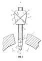
図1および図2を参照すると、縫合器具100は、概して、長手方向軸A−Aを規定する細長いシャフト110と、細長いシャフト110に並進可能に取り付けられる軌道ガイド120と、細長いシャフト110の遠位端部分112に動作可能に連結されるイントロデューサガード部材130とを含む。軌道ガイド120は、細長いシャフト110に並進可能に取り付けられ、細長いシャフト110に沿った所望の位置に軌道ガイド120を確実に固定するロッキング機構(図示されていない)を含む。従って、軌道ガイド120とイントロデューサガード部材130との間の距離は、患者の解剖学的構造に基づいて調整され得る。イントロデューサガード部材130は、一対のアーム部材132、134を含む。より詳細に下記に考察されるように、アーム部材132、134は、アーム部材132、134が引き込められ、図1に示されるように長手方向軸「A−A」と実質的に一列に並んだ第1の位置から、アーム部材132、134が展開され、図2に示されるように横断方向軸「B−B」または例えば長手方向軸「A−A」に関して鋭角を規定する第2の位置に可動である。 With reference to FIGS. 1 and 2, the
引き続き図1および図2を参照すると、軌道ガイド120は、組織「T」における開口部の中に軌道ガイド120を挿入/除去することを容易にする概して先細の構成を含む。軌道ガイド120は、軌道ガイドの近位端部分から軌道ガイドの遠位端部分に斜めに延び、それによって、長手方向軸「A−A」に関して角度を形成する(例示的目的のために想像線で示される)穴122、124を規定する。穴122は長手方向軸「D−D」を規定し、穴124は長手方向軸「E−E」を規定する。穴122、124は、例えば縫合糸を操作するように構成される外科手術器具などの1つ以上の種類の外科手術器具を受容するように寸法設定され得る。長手方向軸「A−A」に関して穴122、124の各々によって規定される角度は、図4に示されるように、縫合糸「S」が組織「T」を貫通するようにイントロデューサガード部材130に結合している穴122、124が適切な構成を提供するように、特定の処置のニーズに合わせて作られ得る。例えば、メッシュ148が組織「T」の開口部の後部側に対してきつく覆うことを確実にするためにより広いメッシュ148が選ばれる場合、より大きい角度が選択される必要がある。さらに、より大きい角度を選ぶことによって、縫合糸「S」は組織「T」における開口部から離れて組織「T」の後部側に入り、このことは縫合された組織「T」の引き裂きを抑制し得る。軌道ガイド120を通ってさらに他の外科手術器具を収容するために、追加の穴が軌道ガイド120に規定され得ることもまた想定され得る。 With continued reference to FIGS. 1 and 2, the
引き続き図1および図2を参照すると、イントロデューサガード部材130は、細長いシャフト110の遠位端部分112に動作可能に接続される。例示される実施形態において、アーム部材132の近位端136は、組織「T」の開口部を通ってイントロデューサガード部材130の挿入/除去を容易にするために、アーム部材132が長手方向軸「A−A」と実質的に一列に並んでヒンジで引き込められ得るように、細長いシャフトの110の遠位端部分112にヒンジで連結される。アーム部材134の近位端は、実質的に同様であり、図示されない。ヒンジで連結されたアーム132、134はまた、図1に示される矢印「X」の方向に展開され得、その結果、展開されたアーム部材132、134は、横断方向軸「B−B」を規定する。図2に示されるように、展開されたアーム部材132、134は、長手方向軸「A−A」と実質的に直交している。 With continued reference to FIGS. 1 and 2, the
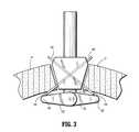
ここで図3〜図5を参照すると、アーム部材132、134の第1の表面152上の、より詳細には、アーム部材132のフリー端部140およびアーム部材134のフリー端部142に隣接して配置される、一対の取り付け部材144、146を含むイントロデューサガード部材130が例示される。取り付け部材144、146は、図4および図4Aに示されるように、縫合糸「S」の端部を解放可能に保持するように構成されるプロングまたはピンの形態であり得る。縫合糸「S」の各端部は、例えば、図4および図4Aに示されるように、縫合糸「S」が取り付け部材144、146の各々に解放可能に固定され得るようにループを形成し得る。代案において、アーム部材132のフリー端部140およびアーム部材134のフリー端部142に縫合糸「S」の一部分を固定するかまたは締め付けるように寸法設定されるスリットが利用され得、その結果、アーム部材132、134が第1の位置から第2の位置に展開される場合、縫合糸「S」はスリットから外れないかまたは解放されない。さらに、図4Bに示されるように、イントロデューサガード部材130は、組織「T」における開口部の中に導入される場合、イントロデューサガード部材130を少なくとも部分的に囲むメッシュ148を含む。メッシュ148は、縫合糸「S」に接続され、縫合糸「S」は、取り付け部材144、146の各々に縫合糸「S」の各端部を固定することによって、イントロデューサガード部材130にメッシュ148を固定する。メッシュ148に余分の縫合糸「S」を解放可能に保持するために低粘着性接着剤がメッシュ148に用いられ得、その結果、余分の縫合糸「S」は行なわれている処置を妨げない。あるいは、図4Cに示されるように、余分の縫合糸「S」は、エッジに溶接される2ピースメッシュ148aによって規定されるポケット内に収納され得る。2ピースメッシュ148aは、上部メッシュ部分149aと、下部メッシュ部分149bとを含む。上部メッシュ部分149aは、穴153であって、そこを縫合糸「S」が通過する、穴153を規定する。余分の縫合糸「S」は、縫合糸「S」またはメッシュ148aを引き裂くことなく、第1の位置から第2の位置にアーム部材132、134が動くことを可能にする。そのようなものとして、アーム部材132、134が第1の位置にあるとき、ポケットに収納される余分の縫合糸「S」は行われている処置を妨げない。 Referring now to FIGS. 3-5, on the first surface 152 of the
アーム部材132、134が組織「T」における開口部に展開されると、図4に示されるように、余分の縫合糸「S」はメッシュ148から解放され、メッシュ148はイントロデューサガード部材130の第2の表面150に配置される。メッシュ148は、吸収可能材料および/または任意の適切な生体適合材料から作られ得る。メッシュ148は、切開創ヘルニアに対する予防を提供する。 When the
図3〜図5に例示される実施形態において、一対のカニューレ挿入針160、162であって、その各々はそれを通る内腔を規定する、一対のカニューレ挿入針160、162が軌道ガイド120の穴122、124に提供される。カニューレ挿入針160は軌道ガイド120の穴122を通ってスライド可能に延びるように寸法設定され、カニューレ挿入針162は軌道ガイド120の穴124を通ってスライド可能に延びるように寸法設定される。イントロデューサガイド部材130が第2の位置、すなわちアーム部材132、134が展開されている場合、長手方向軸「D−D」は取り付け部材144と一列に並んでおり、長手方向軸「E−E」は、取り付け部材146と一列に並んでいる。カニューレ挿入針160、162は、穴122、124を通って延び、(例えば、腹腔の筋膜などの)組織「T」を貫通するように提供される。カニューレ挿入針160、162は、組織「T」を通って動き、イントロデューサガード部材130の第1の表面152に達するまでさらに遠位に延びる。縫合糸「S」を解放可能に固定するように働く取り付け部材144、146はまた、それぞれ、カニューレ挿入針160、162がアーム部材132、134のフリー端部140、142を越えて延びるのを防ぐカニューレ挿入針ストッパとして働く。 In the embodiment illustrated in FIGS. 3-5, a pair of cannula insertion needles 160, 162, each of which defines a lumen therethrough, the pair of cannula insertion needles 160, 162 includes a
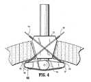
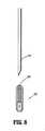
特に図4を参照すると、一対のロッド164、166であって、その各々がそれらの遠位端に連結される留め構造を有する、一対のロッド164、166が提供される。留め構造は、例えばフック170であり得る。しかしながら、他の留め構造が用いられ得る。例えば、図8に示されるように、フェルールアセンブリ300は、アーム部材132のフリー端部140およびアーム部材134のフリー端部142に隣接して配置され得る。フェルールアセンブリ300は、縫合糸「S」の一部分を保持するように適合されるフェルール360を解放可能に保持するように構成される。針350の遠位端は、縫合糸「S」に沿ってフェルールアセンブリ300からフェルール360を除去するためにフェルールアセンブリ300内のフェルール360を係合するように構成される。フェルール360は、針350の開放遠位端を摩擦で係合する。針350がまた例えば磁気係合または接着係合などによってフェルール360を係合し得ることがさらに意図される。 With particular reference to FIG. 4, a pair of
ロッド164、166は、カニューレ挿入針160、162の内腔を通ってスライド可能に延びるように寸法設定される。カニューレ挿入針160、162の内腔を通って延びるロッド164、166は、イントロデューサガード部材130の第1の表面152上の取り付け部材144、146の方に向けられる。ロッド164、166の遠位端部分に提供されるフック170を利用することによって、外科医は、取り付け部材144、146に固定された縫合糸「S」のループ状の端部を捕捉するために比較的遠隔の位置からロッド164、166を操作し得る。その後、図5に示されるように、ロッド164、166は、ここで縫合糸「S」のループ状の端部を係合し、近位にかつ軌道ガイド120から出るように引かれ得、それによって、縫合糸「S」のループ状の端部を取り付け部材144、146から係合を解放する。その結果として、縫合糸「S」のループ状の端部は、軌道ガイド120から引き出される。その後、縫合糸「S」のループ状の端部は、カニューレ挿入針160、162が軌道ガイド120から引き抜かれ得るようにロッド164、166から係合解放される。ロッド164、166およびカニューレ挿入針160、162を軌道ガイド120から抜き取ると、最初に軌道ガイド120のロック機構を解放し、イントロデューサガイド部材130のアーム部材132、134を第1の位置に引き込めることによって、縫合器具100は今、組織「T」における開口部から除去される準備が整っている。その後、メッシュ148に接続されている縫合糸「S」は、より詳細に以下に考察されるように、組織「T」をくっつけるように結び付けられる準備が整っている。 The
縫合デバイス100の動作は、図1〜図7を参照してここで説明される。以下の説明において、縫合デバイス100が使用する準備が整っている状態であることが想定されている。具体的には、メッシュ148は、縫合糸「S」によってアーム部材132、134の第2の表面150に固定されており、縫合糸「S」は、アーム部材132の取り付け部材144およびアーム部材134の取り付け部材146に解放可能に固定される(図4に最もよくわかるように)。 The operation of the
最初に、イントロデューサガード部材130が細長いシャフト110の長手方向軸「A−A」と実質的に一列に並んだ引き込められた位置で、縫合デバイス100は、例えば、トロカール、栓塞子または類似のものによって作られる、組織「T」における開口部の中に挿入される。細長いシャフト110の遠位部分は最初に組織「T」における開口部を通って挿入され、軌道ガイド120は組織「T」における開口部の中に確実に押し込まれる。外科医は、細長いシャフト110に沿って軌道ガイド120を動かすことによって、患者の解剖学的構造に基づいて軌道ガイド120とイントロデューサガード部材130との間の距離を調整する。一旦所望の距離が達成されると、軌道ガイド120のロッキング機構は、細長いシャフト110の所望の位置に軌道ガイド120を確実に固定するために利用される。あるいは、外科医は、組織「T」における開口部に軌道ガイド120の位置を決め得、軌道ガイド120に対して細長いシャフト110を動かし、イントロデューサガード部材130の位置を調整し得る。図4Bに示されるように、軌道ガイド120とイントロデューサガード部材130との間の距離が変化した場合、角度の変化に対応する(account for)ために、軌道ガイド120は、追加の穴122a、124aのセットであって、その各々が長手方向軸「K−K」、「L−L」を規定する、追加の穴122a、124aのセットを含み得る。広範囲の患者および行われる処置にさらに適応するために、軌道ガイド120が複数の穴をさらに含み得ることが意図される。さらに、細長いシャフト110は、軌道ガイド120とイントロデューサガード部材130との間の距離に関係してどの穴を使用すべきかを示すインディシアを含み得る。軌道ガイド120の先細の構成は、軌道ガイドを組織「T」における開口部に固定することを容易にする。軌道ガイド120を組織「T」における開口部に固定すると、細長いシャフト110の遠位端部分112にヒンジで連結されるイントロデューサガード部材130のアーム部材132、134は、図1に示される矢印「X」の方向に作動機構によって展開される。細長いシャフト110に連結されるイントロデューサガード部材130がまたカム経路、回転要素などの他のリンク機構を含み得ることもまた意図される。 Initially, in the retracted position where the
作動機構は、空気圧作動機構または水圧作動機構を含み得る。空気圧作動機構は、例えば、圧縮空気、二酸化炭素、または類似のものなどの加圧気体を用い、引き込められた位置からアーム部材132、134を展開し得る。他方、水圧作動機構は、例えば、滅菌水、食塩水、または類似のものなどの液体を用い、アーム部材132、134を展開する機械的動作を引き起こし得る。空気圧作動機構および水圧作動機構は、可搬式機構または非可搬式機構であり得る。 The actuation mechanism may include a pneumatic actuation mechanism or a hydraulic actuation mechanism. The pneumatic actuation mechanism may deploy the
展開されたアーム部材132、134は、ここで長手方向軸「A−A」に実質的に直交である態様で向けられ、それによって、横断方向軸「B−B」を規定する。この時点において、穴の長手方向軸「D−D」、「E−E」は、アーム部材132のフリー端部140およびアーム部材134のフリー部材142に隣接して配置される取り付け部材144、146に整列する。 The deployed
図3を参照すると、カニューレ挿入針160はそれを通る内腔を有し、穴122を通ってスライド可能に挿入され、カニューレ挿入針162はそれを通る内腔を有し、穴124を通ってスライド可能に挿入される。長手方向軸「D−D」を規定する穴122は、組織「T」を通って取り付け部材144の方にカニューレ挿入針160を導き、長手方向軸「E−E」を規定する穴124は、組織「T」を通って取り付け部材146の方にカニューレ挿入針162を導く。カニューレ挿入針160は取り付け部材144によってアーム部材140のフリー端部を越えて延びるのを妨げられ、カニューレ挿入針162は取り付け部材146によってアーム部材142のフリー端部を越えて延びるのを妨げられる。取り付け部材144、146に到達すると、カニューレ挿入針160、162は、イントロデューサガード部材130の第1の表面152と接触するようになる。 Referring to FIG. 3,
図4を参照すると、カニューレ挿入針160を通る内腔を有するカニューレ挿入針160をアーム部材132の第1の表面152に配置すると、ロッド164はカニューレ挿入針160の内腔を通ってスライド可能に挿入され、カニューレ挿入針162を通る内腔を有するカニューレ挿入針162をアーム部材134の第1の表面152に配置すると、ロッド166はカニューレ挿入針162の内腔を通ってスライド可能に挿入される。ロッド164、166は、取り付け部材144、146に固定される縫合糸「S」のループ状の端部を有する取り付け部材144、146に隣接して、カニューレ挿入針160、162を出る。ロッド164、166の遠位端部分に提供されるフック170などのキャッチング構造は、比較的遠隔の場所からロッド164、166を操作することによって、縫合糸「S」のループ状の端部を捕捉するために利用される。取り付け部材144、146に解放可能に固定される縫合糸「S」のループ状の端部は、フック170によって捕捉され、取り付け部材144、146から係合解放される。 Referring to FIG. 4, when a
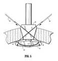
図5を参照すると、ここで取り付け部材144から係合解放された縫合糸「S」のループ状の端部は、縫合糸「S」の端部が軌道ガイド120の近位端部分に隣接して穴122から引き抜かれるまで、カニューレ挿入針160の内腔を通って近位に引かれ、ここで取り付け部材146から係合解放された縫合糸「S」のループ状の端部は、縫合糸「S」の端部が軌道ガイド120の近位端部分に隣接して穴124から引き抜かれるまで、カニューレ挿入針162の内腔を通って近位に引かれる。縫合糸「S」のループ状の端部の抜き取り後、カニューレ挿入針160、162およびロッド164、166は、縫合糸「S」がここで組織「T」を直接に貫通するように軌道ガイド120から除去される。カニューレ挿入針160、162を除去すると、縫合器具100は、最初にアーム132、134を引き込まれた位置に配置し、軌道ガイド120のロッキング機構を解放し、軌道ガイド120が細長いシャフト110に沿って並進可能にすることによって、組織「T」から近位に引き抜かれ得る。ここで細長いシャフト110に沿って並進可能である軌道ガイド120は、近位に並進させられ、組織「T」における開口部から係合解放する。同時に細長いシャフト110は、わずかに遠位に押され得、イントロデューサガード部材130が長手方向軸「A−A」と実質的に一列に並んでいる初期位置にアーム部材132、134が引き込むのに十分なスペースを提供し得る。図6に示されるように、長手方向軸「A−A」と実質的に一列に並んでいる軌道ガイド120は、組織「T」における開口部から引き抜かれ、それによって、縫合糸「S」のループ状の端部は、軌道ガイド120の遠位端部分から穴122、124を出る。この時点で、縫合器具100は、縫合糸「S」がメッシュ148を含み適切な場所で組織「T」を直接に貫通した状態で、組織「T」における開口部から引き抜かれる。 Referring now to FIG. 5, the looped end of the suture “S” now disengaged from the
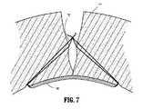
より詳細に以下に考察されるように、縫合器具100を組織「T」の開口部から除去した後、メッシュ148を有する縫合糸「S」は、組織「T」に対して適切な場所にとどまり、ここで組織をくっつけるように結びつけられる準備が整っている。上記に考察されるように、長手方向軸「A−A」に関する穴122、124の角度およびアーム部材132、134の長さは、行われている処置の適切なニーズに合わせて特別に作られ得る。例えば、メッシュ148が組織「T」の開口部の後部側に対してきつく覆うことを確実にするためにより大きいメッシュ148が選ばれる場合、より大きい角度が選択される必要がある。さらに、より大きい角度を選ぶことによって、縫合糸「S」は組織「T」における開口部から離れて組織「T」の後部側に入り、このことは縫合された組織「T」の引き裂きを抑制し得る。図7を参照すると、縫合糸「S」のループ状の端部は、メッシュ148を組織「T」の第2の表面にメッシュ148を提供する一方、ここで組織をくっつけるように結びつけられる準備が整っている。 As discussed in more detail below, after removal of
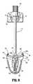
図9に示されるように、アクチュエータアセンブリ500が、本開示の縫合デバイス100と共に用いられ得、第1の位置から第2の位置にまたはその逆にアーム部材132
、134を作動させ得ることが意図される。アクチュエータアセンブリ500は、ノブ540と、ベースアセンブリ560とを含む。ノブアセンブリ540およびベースアセンブリ560は、細長いシャフト110によって連結される。ベース560は穴561を規定し、穴561において付勢部材562はシャフト110と縦に一列に並んで収納される。アーム部材532は、ピボット535aの周りを回るようにベース560の係合部分536にヒンジで連結され、アーム部材534は、ピボット535bの周りを回るようにベース560の係合部分536にヒンジで連結される。アーム部材532、534の各々は、シャフト110から横に突き出るピン538をスロット537にスライド可能に収容するスロット537を規定する(アーム部材534に規定されるスロット537のみが図9に示される)。ノブ540がオペレータによって遠位に押圧されると、シャフト110のピン538は、ベース560の係合部分536に関して遠位に並進し、スロット537は、アーム部材532、534をそれぞれ引き込められた位置(第1の位置)に進める。この時点で、アーム部材532、534は、シャフト110と縦方向に一列に並べられ、組織「T」における開口部の中に挿入される準備が整っている。ロッキング機構(図示されていない)がアーム部材532、534を第1の位置にロックするために提供され得ることがさらに意図される。図9に示されるように、オペレータによってノブ540が解放されると、付勢部材562は、ピン538が近位に並進するようにベース560の係合部分536に関して近位にシャフト110を動かし、このことは、次にアーム部材532、534が第2の位置に展開されるように進める。メッシュ148はまた、縫合糸「S」によってアーム部材532、534に取り付けられ得る。上記に考察されるように、縫合糸「S」の端部を解放可能に保持するように構成されるプロングまたはピンの形態である取り付け部材144、146は、アーム部材532、534に提供され得る。As shown in FIG. 9, an
, 134 can be actuated.
前述の事項および様々な図面を参照して、当業者は、本開示の範囲から逸脱することなく特定の修正もまた本開示に対してなされ得ることを理解する。本開示のいくつかの実施形態が図面において示されたが、本開示がそれらの実施形態に限定されることは意図されない。なぜなら、技術が許容する限り本開示が広い範囲であること、および明細書も同様に読まれるべきであることが意図されるからである。従って、上記の説明は、限定するものとして解釈されるべきではなく、特定の実施形態の単なる例示として解釈されるべきである。当業者は、本明細書に添付された請求項の範囲および精神内の他の修正を想定する。 With reference to the foregoing and various drawings, those skilled in the art will recognize that certain modifications can also be made to the disclosure without departing from the scope of the disclosure. Although several embodiments of the present disclosure have been shown in the drawings, it is not intended that the present disclosure be limited to those embodiments. This is because the present disclosure is intended to be as broad as the technology allows and the specification should be read as well. Therefore, the above description should not be construed as limiting, but merely as exemplifications of particular embodiments. Those skilled in the art will envision other modifications within the scope and spirit of the claims appended hereto.
100 縫合器具
110 細長いシャフト
112 遠位部分
120 軌道ガイド
122、124 穴
132、134 アーム部材
140、142 自由端部
148 メッシュDESCRIPTION OF
Claims (23)
Translated fromJapanese該細長いシャフトに取り付けられる軌道ガイドであって、該軌道ガイドは、該軌道ガイドを通る少なくとも1つの穴を規定する、軌道ガイドと、
該細長いシャフトに動作可能に連結されるイントロデューサガード部材であって、該イントロデューサガード部材は少なくとも1つのアーム部材を含み、該少なくとも1つのアーム部材は該アーム部材が引き込められ、該長手方向軸と一列に並んだ第1の位置と、該少なくとも1つのアーム部材が展開される第2の位置との間で可動である、イントロデューサガード部材と
を備えている、縫合デバイス。An elongated shaft defining a longitudinal axis;
A track guide attached to the elongate shaft, the track guide defining at least one hole through the track guide;
An introducer guard member operatively coupled to the elongate shaft, the introducer guard member including at least one arm member, the at least one arm member being retracted and the longitudinal direction An introducer guard member movable between a first position in line with the shaft and a second position where the at least one arm member is deployed.
Applications Claiming Priority (4)
| Application Number | Priority Date | Filing Date | Title |
|---|---|---|---|
| US36881510P | 2010-07-29 | 2010-07-29 | |
| US61/368,815 | 2010-07-29 | ||
| US13/117,317US8906042B2 (en) | 2010-07-29 | 2011-05-27 | Wound closure device including mesh barrier |
| US13/117,317 | 2011-05-27 |
Publications (1)
| Publication Number | Publication Date |
|---|---|
| JP2012030067Atrue JP2012030067A (en) | 2012-02-16 |
Family
ID=44510819
Family Applications (1)
| Application Number | Title | Priority Date | Filing Date |
|---|---|---|---|
| JP2011152263ACeasedJP2012030067A (en) | 2010-07-29 | 2011-07-08 | Wound closure device including mesh barrier |
Country Status (5)
| Country | Link |
|---|---|
| US (2) | US8906042B2 (en) |
| EP (1) | EP2412317B1 (en) |
| JP (1) | JP2012030067A (en) |
| AU (1) | AU2011202923A1 (en) |
| CA (1) | CA2742457A1 (en) |
Cited By (1)
| Publication number | Priority date | Publication date | Assignee | Title |
|---|---|---|---|---|
| CN105848592A (en)* | 2014-11-21 | 2016-08-10 | 金基成 | Surgical Sutures for Laparoscopic Access Site Closure Devices |
Families Citing this family (51)
| Publication number | Priority date | Publication date | Assignee | Title |
|---|---|---|---|---|
| US7662161B2 (en) | 1999-09-13 | 2010-02-16 | Rex Medical, L.P | Vascular hole closure device |
| EP2166954A1 (en) | 2007-07-13 | 2010-03-31 | Rex Medical, L.P. | Vascular hole closure device |
| US8920463B2 (en) | 2008-02-15 | 2014-12-30 | Rex Medical, L.P. | Vascular hole closure device |
| US8491629B2 (en) | 2008-02-15 | 2013-07-23 | Rex Medical | Vascular hole closure delivery device |
| US8070772B2 (en) | 2008-02-15 | 2011-12-06 | Rex Medical, L.P. | Vascular hole closure device |
| US20110029013A1 (en) | 2008-02-15 | 2011-02-03 | Mcguckin James F | Vascular Hole Closure Device |
| US8920462B2 (en) | 2008-02-15 | 2014-12-30 | Rex Medical, L.P. | Vascular hole closure device |
| US9226738B2 (en) | 2008-02-15 | 2016-01-05 | Rex Medical, L.P. | Vascular hole closure delivery device |
| JP5720031B2 (en) | 2009-01-12 | 2015-05-20 | テレフレックス メディカル インコーポレイテッドTeleflex Medical Incorporated | Apparatus and method for tissue closure |
| US8906042B2 (en)* | 2010-07-29 | 2014-12-09 | Covidien Lp | Wound closure device including mesh barrier |
| KR101082762B1 (en)* | 2011-02-18 | 2011-11-10 | 이정삼 | Laparoscopic Traction System |
| AU2012202202B2 (en)* | 2011-07-20 | 2017-05-11 | Rex Medical, L.P. | Vascular hole closure delivery device |
| US20130035701A1 (en)* | 2011-08-04 | 2013-02-07 | Suture Ease, LLC | Dual insufflation and wound closure devices ans methods |
| WO2013043256A1 (en) | 2011-09-23 | 2013-03-28 | Coopersurgical, Inc. | Endoscopic ports and related kits |
| EP2797519B1 (en)* | 2011-12-27 | 2023-05-31 | CooperSurgical, Inc. | Suture passer guides and related kits |
| CA2860645C (en) | 2012-01-04 | 2019-11-05 | Teleflex Medical Incorporated | Apparatus and methods for tissue closure |
| US9393011B2 (en) | 2012-03-13 | 2016-07-19 | Suture Ease, Inc. | Needle and snare guide apparatus for passing suture |
| US9668727B2 (en) | 2012-03-13 | 2017-06-06 | Suture Ease, Inc. | Needle and snare guide apparatus for passing suture |
| WO2013158742A2 (en)* | 2012-04-18 | 2013-10-24 | Cook Biotech Incorporated | Surgical grafts, and implements for delivering same |
| WO2013172916A1 (en) | 2012-05-18 | 2013-11-21 | Coopersurgical, Inc. | Suture passer guides and related kits and methods |
| WO2014205279A1 (en)* | 2013-06-19 | 2014-12-24 | Endolutions, Llc | Apparatus and method for fascial closure device for laparoscopic trocar port site and surgery |
| US10258324B2 (en)* | 2013-08-02 | 2019-04-16 | Covidien Lp | Devices, systems, and methods for providing surgical access and facilitating closure of surgical access openings |
| US9510823B2 (en) | 2013-08-02 | 2016-12-06 | Covidien Lp | Devices, systems, and methods for wound closure |
| US9848879B2 (en) | 2013-08-02 | 2017-12-26 | Covidien Lp | Devices, systems, and methods for wound closure |
| US10070851B2 (en) | 2013-08-02 | 2018-09-11 | Covidien Lp | Devices, systems, and methods for wound closure |
| WO2015120258A1 (en) | 2014-02-07 | 2015-08-13 | Medeon Biosurgical, Inc. | Suture delivery device for suturing tissue |
| US10327761B2 (en) | 2014-02-07 | 2019-06-25 | Medeon Biodesign, Inc. | Suture delivery device for suturing tissue |
| US10299785B2 (en) | 2016-04-01 | 2019-05-28 | Ethicon Llc | Surgical access devices with integrated wound closure features |
| US11026676B2 (en) | 2017-02-06 | 2021-06-08 | Covidien Lp | Surgical wound closure apparatus |
| US10485580B2 (en) | 2017-06-29 | 2019-11-26 | Ethicon Llc | Trocar with oblique needle insertion port and coplanar stopcock |
| US10709473B2 (en) | 2017-06-29 | 2020-07-14 | Ethicon Llc | Trocar obturator with detachable rotary tissue fastener |
| US10939937B2 (en) | 2017-06-29 | 2021-03-09 | Ethicon Llc | Trocar with oblique needle insertion port and perpendicular seal latch |
| US10568619B2 (en) | 2017-06-29 | 2020-02-25 | Ethicon Llc | Surgical port with wound closure channels |
| US10639029B2 (en) | 2017-06-29 | 2020-05-05 | Ethicon Llc | Suture grasping instrument |
| US10639068B2 (en) | 2017-06-29 | 2020-05-05 | Ethicon Llc | Trocar with oblique needle insertion port and perpendicular seal latch |
| US10709440B2 (en) | 2017-06-29 | 2020-07-14 | Ethicon Llc | Suture passing instrument with puncture site identification feature |
| US11389192B2 (en) | 2017-06-29 | 2022-07-19 | Cilag Gmbh International | Method of suturing a trocar path incision |
| US10869690B2 (en) | 2017-06-29 | 2020-12-22 | Ethicon Llc | Trocar obturator with transverse needle ports |
| US10675018B2 (en) | 2017-06-29 | 2020-06-09 | Ethicon Llc | Needle guide instrument with transverse suture capture feature |
| US11129609B2 (en) | 2018-04-24 | 2021-09-28 | Covidien Lp | Devices, systems, and methods for providing surgical access and facilitating closure of surgical access openings |
| US11234690B2 (en) | 2018-05-02 | 2022-02-01 | Covidien Lp | Method and device for closing a port site incision |
| US11213288B2 (en) | 2018-05-02 | 2022-01-04 | Covidien Lp | Port site closure instrument |
| CN111374722B (en)* | 2018-12-29 | 2025-04-08 | 江苏风和医疗器材股份有限公司 | Suture assembly, puncture core assembly with suture assembly and puncture outfit |
| US11504105B2 (en) | 2019-01-25 | 2022-11-22 | Rex Medical L.P. | Vascular hole closure device |
| CN111096769B (en)* | 2019-12-31 | 2024-12-10 | 清华大学 | Auxiliary suturing device for hollow organs |
| US12383246B2 (en) | 2020-10-12 | 2025-08-12 | Abbott Cardiovascular Systems, Inc. | Vessel closure device with improved safety and tract hemostasis |
| EP4259008A4 (en)* | 2020-12-11 | 2024-06-26 | Neurofine Corp. | VASCULAR OCCLUSION DEVICES AND METHODS |
| USD1029259S1 (en) | 2021-08-31 | 2024-05-28 | New Wave Endo-Surgical Corp. | Portion of a medical device |
| USD1002009S1 (en) | 2021-08-31 | 2023-10-17 | New Wave Endo-Surgical Corp. | Medical device |
| EP4190246A1 (en) | 2021-12-06 | 2023-06-07 | Universität Zürich | Device for closing a tissue opening |
| CN120456870A (en) | 2022-12-22 | 2025-08-08 | 科维医疗股份公司 | Minimally invasive suturing device |
Citations (5)
| Publication number | Priority date | Publication date | Assignee | Title |
|---|---|---|---|---|
| US20010031973A1 (en)* | 1995-08-24 | 2001-10-18 | Nobles Anthony A. | Suturing device and method for sealing an opening in a blood vessel or other biological structure |
| US20060030868A1 (en)* | 2004-08-05 | 2006-02-09 | Bennett Richard M Iii | Laparoscopic port site closure tool |
| US20080033459A1 (en)* | 2006-08-03 | 2008-02-07 | Surgsolutions, Llp | Suturing apparatus for closing tissue defects |
| WO2008099382A1 (en)* | 2007-02-14 | 2008-08-21 | Easylap Ltd. | Mesh deployment apparatus |
| WO2010081096A2 (en)* | 2009-01-12 | 2010-07-15 | Option 3, Llc | Apparatus and methods for tissue closure |
Family Cites Families (37)
| Publication number | Priority date | Publication date | Assignee | Title |
|---|---|---|---|---|
| US4007743A (en) | 1975-10-20 | 1977-02-15 | American Hospital Supply Corporation | Opening mechanism for umbrella-like intravascular shunt defect closure device |
| US4733664A (en) | 1983-12-01 | 1988-03-29 | University Of New Mexico | Surgical clip, applier, and method |
| US6036699A (en)* | 1992-12-10 | 2000-03-14 | Perclose, Inc. | Device and method for suturing tissue |
| US5507755A (en)* | 1993-08-03 | 1996-04-16 | Origin Medsystems, Inc. | Apparatus and method for closing puncture wounds |
| US5397332A (en)* | 1993-09-02 | 1995-03-14 | Ethicon, Inc. | Surgical mesh applicator |
| US5470338A (en) | 1993-10-08 | 1995-11-28 | United States Surgical Corporation | Instrument for closing trocar puncture wounds |
| EP0902649B1 (en) | 1996-05-10 | 2001-09-05 | Karl Storz GmbH & Co. KG | Suturing aid |
| US6024748A (en) | 1996-07-23 | 2000-02-15 | United States Surgical Corporation | Singleshot anastomosis instrument with detachable loading unit and method |
| US7235087B2 (en) | 1999-03-04 | 2007-06-26 | Abbott Park | Articulating suturing device and method |
| US8137364B2 (en) | 2003-09-11 | 2012-03-20 | Abbott Laboratories | Articulating suturing device and method |
| US7842048B2 (en) | 2006-08-18 | 2010-11-30 | Abbott Laboratories | Articulating suture device and method |
| US7226467B2 (en) | 1999-04-09 | 2007-06-05 | Evalve, Inc. | Fixation device delivery catheter, systems and methods of use |
| US6911032B2 (en) | 1999-11-18 | 2005-06-28 | Scimed Life Systems, Inc. | Apparatus and method for compressing body tissue |
| US7083628B2 (en) | 2002-09-03 | 2006-08-01 | Edwards Lifesciences Corporation | Single catheter mitral valve repair device and method for use |
| WO2001095809A1 (en) | 2000-06-14 | 2001-12-20 | Sterilis, Inc. | Suturing method and apparatus |
| US6551330B1 (en) | 2000-09-21 | 2003-04-22 | Opus Medical, Inc. | Linear suturing apparatus and methods |
| US20090143808A1 (en) | 2001-04-24 | 2009-06-04 | Houser Russell A | Guided Tissue Cutting Device, Method of Use and Kits Therefor |
| US6776784B2 (en) | 2001-09-06 | 2004-08-17 | Core Medical, Inc. | Clip apparatus for closing septal defects and methods of use |
| US6743241B2 (en) | 2002-03-01 | 2004-06-01 | Intellimed Surgical Solutions Llc | Laparoscopic port site fascial closure device |
| JP3890589B2 (en) | 2002-04-15 | 2007-03-07 | ニプロ株式会社 | Intracardiac suture device |
| US7160309B2 (en) | 2002-12-31 | 2007-01-09 | Laveille Kao Voss | Systems for anchoring a medical device in a body lumen |
| US7449024B2 (en) | 2003-12-23 | 2008-11-11 | Abbott Laboratories | Suturing device with split arm and method of suturing tissue |
| US7211093B2 (en) | 2004-01-14 | 2007-05-01 | Lsi Solutions, Inc. | Sew-right running stitch instrument |
| US7500972B2 (en) | 2004-05-07 | 2009-03-10 | Ethicon Endo-Surgery, Inc. | Device for alternately holding, or effecting relative longitudinal movement, of members of a medical instrument |
| EP1611850A1 (en) | 2004-06-28 | 2006-01-04 | Cardio Life Research S.A. | Occlusion and tight punction device for an anatomical structure |
| US8172857B2 (en) | 2004-08-27 | 2012-05-08 | Davol, Inc. | Endoscopic tissue apposition device and method of use |
| CN101027001B (en) | 2004-09-27 | 2010-05-26 | 苏图诺有限公司 | Handle for suturing apparatus |
| US7708748B2 (en) | 2005-03-30 | 2010-05-04 | Ethicon Endo-Surgery, Inc. | Anastomosis device |
| US7645286B2 (en)* | 2005-05-20 | 2010-01-12 | Neotract, Inc. | Devices, systems and methods for retracting, lifting, compressing, supporting or repositioning tissues or anatomical structures |
| CA2703129C (en) | 2007-10-18 | 2016-02-16 | Neochord Inc. | Minimially invasive repair of a valve leaflet in a beating heart |
| EP2389118B1 (en) | 2009-01-26 | 2019-05-15 | Synthes GmbH | Bi-directional suture passer |
| CA2754720A1 (en) | 2009-03-11 | 2010-09-16 | Synthes Usa, Llc | Threadable knot soft tissue defect repair system |
| US8591529B2 (en) | 2009-10-01 | 2013-11-26 | Covidien Lp | Wound closure device including direct-driven needle |
| US20110082475A1 (en) | 2009-10-01 | 2011-04-07 | Tyco Healthcare Group Lp | Wound closure device including ferrule ejector system |
| US20110082480A1 (en) | 2009-10-01 | 2011-04-07 | Tyco Healthcare Group Lp | Wound closure device including pivotable claws |
| US8435252B2 (en) | 2009-11-11 | 2013-05-07 | Covidien Lp | Wound closure device |
| US8906042B2 (en)* | 2010-07-29 | 2014-12-09 | Covidien Lp | Wound closure device including mesh barrier |
- 2011
- 2011-05-27USUS13/117,317patent/US8906042B2/enactiveActive
- 2011-06-08CACA2742457Apatent/CA2742457A1/ennot_activeAbandoned
- 2011-06-17AUAU2011202923Apatent/AU2011202923A1/ennot_activeAbandoned
- 2011-07-08JPJP2011152263Apatent/JP2012030067A/ennot_activeCeased
- 2011-07-28EPEP11250682.9Apatent/EP2412317B1/ennot_activeNot-in-force
- 2014
- 2014-12-09USUS14/563,667patent/US9687226B2/ennot_activeExpired - Fee Related
Patent Citations (8)
| Publication number | Priority date | Publication date | Assignee | Title |
|---|---|---|---|---|
| US20010031973A1 (en)* | 1995-08-24 | 2001-10-18 | Nobles Anthony A. | Suturing device and method for sealing an opening in a blood vessel or other biological structure |
| JP2001524864A (en)* | 1998-03-09 | 2001-12-04 | スーチュラ,インコーポレイテッド | A suturing device for sealing an opening in a blood vessel or other biological tissue |
| US20060030868A1 (en)* | 2004-08-05 | 2006-02-09 | Bennett Richard M Iii | Laparoscopic port site closure tool |
| US20080033459A1 (en)* | 2006-08-03 | 2008-02-07 | Surgsolutions, Llp | Suturing apparatus for closing tissue defects |
| WO2008099382A1 (en)* | 2007-02-14 | 2008-08-21 | Easylap Ltd. | Mesh deployment apparatus |
| JP2010534490A (en)* | 2007-02-14 | 2010-11-11 | イージーラップ エル・ティー・ディー | Mesh deployment device |
| WO2010081096A2 (en)* | 2009-01-12 | 2010-07-15 | Option 3, Llc | Apparatus and methods for tissue closure |
| JP2012515020A (en)* | 2009-01-12 | 2012-07-05 | アクシオム テクノロジー パートナーズ, エルエルシー | Apparatus and method for tissue closure |
Cited By (2)
| Publication number | Priority date | Publication date | Assignee | Title |
|---|---|---|---|---|
| CN105848592A (en)* | 2014-11-21 | 2016-08-10 | 金基成 | Surgical Sutures for Laparoscopic Access Site Closure Devices |
| JP2017502714A (en)* | 2014-11-21 | 2017-01-26 | ソン キム,キ | Suture for laparoscopic port site closure device |
Also Published As
| Publication number | Publication date |
|---|---|
| US9687226B2 (en) | 2017-06-27 |
| US20120029532A1 (en) | 2012-02-02 |
| US8906042B2 (en) | 2014-12-09 |
| AU2011202923A1 (en) | 2012-02-16 |
| EP2412317B1 (en) | 2019-07-17 |
| EP2412317A1 (en) | 2012-02-01 |
| US20150094741A1 (en) | 2015-04-02 |
| CA2742457A1 (en) | 2012-01-29 |
Similar Documents
| Publication | Publication Date | Title |
|---|---|---|
| JP2012030067A (en) | Wound closure device including mesh barrier | |
| US10631855B2 (en) | Wound closure device including direct-driven needle | |
| JP6246935B2 (en) | Laparoscopic fascia closure system | |
| US6743241B2 (en) | Laparoscopic port site fascial closure device | |
| EP2305129A2 (en) | Wound closure device including ferrule ejector systeme | |
| US20110082473A1 (en) | Wound closure device including releasable barbs | |
| EP3563775B1 (en) | Port site closure instrument | |
| US20150313583A1 (en) | Needle and snare guide apparatus for passing suture | |
| US11471152B2 (en) | Needle and guide apparatus for passing suture | |
| US20180235603A1 (en) | Access and suture apparatus, system, and method of closing tissue |
Legal Events
| Date | Code | Title | Description |
|---|---|---|---|
| A621 | Written request for application examination | Free format text:JAPANESE INTERMEDIATE CODE: A621 Effective date:20140327 | |
| A977 | Report on retrieval | Free format text:JAPANESE INTERMEDIATE CODE: A971007 Effective date:20141021 | |
| A131 | Notification of reasons for refusal | Free format text:JAPANESE INTERMEDIATE CODE: A131 Effective date:20141119 | |
| A521 | Written amendment | Free format text:JAPANESE INTERMEDIATE CODE: A523 Effective date:20150122 | |
| A01 | Written decision to grant a patent or to grant a registration (utility model) | Free format text:JAPANESE INTERMEDIATE CODE: A01 Effective date:20150610 | |
| A045 | Written measure of dismissal of application | Free format text:JAPANESE INTERMEDIATE CODE: A045 Effective date:20151022 |