JP2012029424A - Battery charger and method of charging battery for motor-driven moving body - Google Patents
Battery charger and method of charging battery for motor-driven moving bodyDownload PDFInfo
- Publication number
- JP2012029424A JP2012029424AJP2010164577AJP2010164577AJP2012029424AJP 2012029424 AJP2012029424 AJP 2012029424AJP 2010164577 AJP2010164577 AJP 2010164577AJP 2010164577 AJP2010164577 AJP 2010164577AJP 2012029424 AJP2012029424 AJP 2012029424A
- Authority
- JP
- Japan
- Prior art keywords
- power
- charging
- output
- power storage
- battery
- Prior art date
- Legal status (The legal status is an assumption and is not a legal conclusion. Google has not performed a legal analysis and makes no representation as to the accuracy of the status listed.)
- Pending
Links
Images


Classifications
- Y—GENERAL TAGGING OF NEW TECHNOLOGICAL DEVELOPMENTS; GENERAL TAGGING OF CROSS-SECTIONAL TECHNOLOGIES SPANNING OVER SEVERAL SECTIONS OF THE IPC; TECHNICAL SUBJECTS COVERED BY FORMER USPC CROSS-REFERENCE ART COLLECTIONS [XRACs] AND DIGESTS
- Y02—TECHNOLOGIES OR APPLICATIONS FOR MITIGATION OR ADAPTATION AGAINST CLIMATE CHANGE
- Y02T—CLIMATE CHANGE MITIGATION TECHNOLOGIES RELATED TO TRANSPORTATION
- Y02T10/00—Road transport of goods or passengers
- Y02T10/60—Other road transportation technologies with climate change mitigation effect
- Y02T10/70—Energy storage systems for electromobility, e.g. batteries
- Y—GENERAL TAGGING OF NEW TECHNOLOGICAL DEVELOPMENTS; GENERAL TAGGING OF CROSS-SECTIONAL TECHNOLOGIES SPANNING OVER SEVERAL SECTIONS OF THE IPC; TECHNICAL SUBJECTS COVERED BY FORMER USPC CROSS-REFERENCE ART COLLECTIONS [XRACs] AND DIGESTS
- Y02—TECHNOLOGIES OR APPLICATIONS FOR MITIGATION OR ADAPTATION AGAINST CLIMATE CHANGE
- Y02T—CLIMATE CHANGE MITIGATION TECHNOLOGIES RELATED TO TRANSPORTATION
- Y02T10/00—Road transport of goods or passengers
- Y02T10/60—Other road transportation technologies with climate change mitigation effect
- Y02T10/72—Electric energy management in electromobility
Landscapes
- Charge And Discharge Circuits For Batteries Or The Like (AREA)
- Electric Propulsion And Braking For Vehicles (AREA)
Abstract
Description
Translated fromJapanese本発明は、充電器に関し、特に、電動車両等の電動移動体用バッテリの充電技術に関する。 The present invention relates to a charger, and more particularly to a charging technique for a battery for an electric vehicle such as an electric vehicle.
特許文献1には、種々の移動体へ急速充電用の電力供給ができる急速充電器(急速充電用電力供給装置)が開示されている。 Patent Document 1 discloses a quick charger (rapid charging power supply device) capable of supplying power for rapid charging to various mobile objects.
この急速充電器は、整流器からの直流電力を貯蔵する第一の蓄電手段と、第一の蓄電手段に貯蔵された直流電力を移動体に供給して、この移動体に搭載された第二の蓄電手段を充電する充電回路と、充電回路による第二の蓄電手段の充電時に、整流器から第一の蓄電手段への直流電力の供給を中止する給電制御手段と、を備える。そして、第一の蓄電手段から第二の蓄電手段に供給される直流電力は、移動体側において、第二の蓄電手段の充電条件に適合した電力に制御される。 The quick charger has a first power storage means for storing DC power from the rectifier, and supplies the DC power stored in the first power storage means to the mobile body, and the second power generator mounted on the mobile body. A charging circuit for charging the power storage means; and a power supply control means for stopping the supply of DC power from the rectifier to the first power storage means when the second power storage means is charged by the charging circuit. Then, the DC power supplied from the first power storage means to the second power storage means is controlled on the mobile body side to power that conforms to the charging conditions of the second power storage means.
特許文献1に記載の急速充電器は、充電回路による第二の蓄電手段の充電時に、給電制御手段が、整流器から第一の蓄電手段への直流電力の供給を中止する。したがって、第一の蓄電手段は、一回の充電で第二の蓄電手段を満充電にすることができる大容量のものであることが要求される。このため、コストが高くなる。 In the quick charger described in Patent Document 1, when the second power storage unit is charged by the charging circuit, the power supply control unit stops the supply of DC power from the rectifier to the first power storage unit. Therefore, the first power storage means is required to have a large capacity that can fully charge the second power storage means by one charge. For this reason, cost becomes high.
また、第一の蓄電手段に貯蔵された直流電力を使い切った場合、第一の蓄電手段に十分な直流電力が貯蔵されるまでの間、第二の蓄電手段を充電することができない。つまり、複数の第二の蓄電手段を連続して充電することができない。 Further, when the DC power stored in the first power storage means is used up, the second power storage means cannot be charged until sufficient DC power is stored in the first power storage means. That is, the plurality of second power storage means cannot be continuously charged.
本発明は、上記事情に鑑みてなされたものであり、本発明の目的は、複数の電動移動体用バッテリを連続して効率よく、低コストで充電することができる技術を提供することにある。 This invention is made | formed in view of the said situation, and the objective of this invention is providing the technique which can charge the battery for several electric vehicles continuously and efficiently at low cost. .
上記課題を解決するために、本発明では、交流電力を直流電力に変換するn(但しn≧2)台の交直変換手段と、直流電力を貯蔵する蓄電手段とを併用して、電動移動体用バッテリを充電する。ここで、n台の交直変換手段が出力する直流電力の総和より大きな充電用電力が必要な場合、これらn台の交直変換手段が出力する直流電力に、蓄電手段に貯蔵された直流電力を加算して、電動移動体に供給する。また、m(但しm<n)台の交直変換手段が出力する直流電力の総和以下の充電用電力が必要な場合、n台の交直変換手段の中からm台の交直変換手段を選択し、これらの選択されたm台の交直変換手段が出力する直流電力を電動移動体に供給する一方、選択されなかった交直変換手段のうちの少なくとも1台が出力する直流電力を蓄電手段に供給して、電動移動体用バッテリを充電しながら蓄電手段を充電する。 In order to solve the above-mentioned problem, the present invention uses an electric mobile body that uses n (where n ≧ 2) AC / DC converting means for converting AC power into DC power and power storage means for storing DC power in combination. Charge the battery. Here, when charging power larger than the sum of the DC powers output from the n AC / DC converters is required, the DC power stored in the storage unit is added to the DC power output from the n AC / DC converters. Then, it is supplied to the electric vehicle. Further, when charging power equal to or less than the sum of DC power output from m (where m <n) AC / DC converters is required, m AC / DC converters are selected from n AC / DC converters, DC power output from the selected m AC / DC converters is supplied to the electric vehicle, while DC power output from at least one of the AC / DC converters not selected is supplied to the power storage means. The power storage means is charged while charging the battery for the electric vehicle.
例えば、本発明の充電器は、充電用ラインを介して電動移動体に充電用電力を供給する充電器であって、
交流電力を直流電力に変換するn(但しn≧2)台の交直変換手段と、
直流電力を貯蔵する蓄電手段と、
前記交直変換手段各々の出力先を前記充電用ラインおよび前記蓄電手段のいずれか一方に切り替える切替手段と、
前記切替手段および前記蓄電手段を制御して、前記充電用電力を前記充電用ラインに供給する充電制御手段と、を有し、
前記充電制御手段は、
前記充電用電力が、n台の前記交直変換手段が出力可能な直流電力の総和より大きい場合に、すべて前記交直変換手段の出力先を前記充電用ラインに設定するとともに、前記蓄電手段に貯蔵された直流電力を前記充電用ラインに出力させ、
前記充電用電力が、m台(但しm<n)の前記交直変換手段が出力可能な直流電力の総和以下である場合に、m台の前記交直変換手段の出力先を前記充電用ラインに設定するとともに、当該m台の交直変換手段以外の少なくとも1台の前記交直変換手段の出力先を前記蓄電手段に設定して前記蓄電手段に直流電力を供給する。For example, the charger of the present invention is a charger that supplies electric power for charging to an electric vehicle via a charging line,
N (where n ≧ 2) AC / DC converting means for converting AC power to DC power;
Power storage means for storing DC power;
Switching means for switching the output destination of each of the AC / DC converting means to either the charging line or the power storage means;
Charging control means for controlling the switching means and the power storage means to supply the charging power to the charging line;
The charge control means includes
When the charging power is larger than the sum of direct-current power that can be output from the n AC / DC converting means, all the output destinations of the AC / DC converting means are set to the charging line and stored in the power storage means. Output DC power to the charging line,
When the charging power is equal to or less than the sum of the DC power that can be output by the m (where m <n) AC / DC converters, the output destination of the m AC / DC converters is set to the charging line At the same time, the output destination of at least one of the AC / DC converters other than the m AC / DC converters is set to the power storage unit, and DC power is supplied to the power storage unit.
本発明によれば、n(但しn≧2)台の交直変換手段と蓄電手段とを併用するので、蓄電手段の容量以上の電動移動体用バッテリを満充電にすることができる。また、電動移動体が要求する充電用電力が、m(但しm<n)台の交直変換手段が出力可能な直流電力の総和以下ならば、電動移動体用バッテリを充電しながら、蓄電手段を充電することができる。したがって、複数の電動移動体を連続して効率よく、低コストで充電することができる。 According to the present invention, since n (where n ≧ 2) AC / DC conversion means and the power storage means are used in combination, the battery for the electric mobile body that is greater than the capacity of the power storage means can be fully charged. If the charging power required by the electric mobile body is less than the sum of the DC power that can be output by m (where m <n) AC / DC conversion means, the power storage means is charged while charging the battery for the electric mobile body. Can be charged. Therefore, a plurality of electric vehicles can be charged continuously and efficiently at a low cost.
以下、本発明の一実施の形態について説明する。 Hereinafter, an embodiment of the present invention will be described.
図1は、本発明の一実施の形態に係る充電システムの概略構成図である。 FIG. 1 is a schematic configuration diagram of a charging system according to an embodiment of the present invention.
図示するように、本実施の形態に係る充電システムは、充電器100と、電池システム201が搭載された電気自動車200と、を有する。ここで、電池システム201は、電気自動車200に搭載された電池(車両駆動用バッテリ)203のスペック、残容量、温度、使用履歴等の諸情報に基づき、逐次、充電用電力の指示値を計算し、電気自動車200に設けられた車両側コネクタ202を介して充電器100に指示値を送信する。そして、車両側コネクタ202を介して充電器100から供給された充電用電力を用いて電池203を充電する。 As illustrated, the charging system according to the present embodiment includes a charger 100 and an
充電器100は、図1に示すように、充電ケーブル101と、充電器側コネクタ102と、複数の交直変換部1031〜1034と、交直変換部1031〜1034のそれぞれに対応付けられて設けられた複数のダイオード1041〜1044と、蓄電部105と、電圧調整部106と、ダイオード107と、セレクタ108と、ELB(漏電遮断器)109と、充電制御部110と、を有する。As shown in FIG. 1, the charger 100 is associated with each of a
充電ケーブル101は、充電用ライン111、通信用ライン112等を収容する。ここで、充電用ライン111は、電気自動車200に充電用電力を供給するための電力線であり、通信用ライン112は、電気自動車200と通信を行うための通信線である。 The
充電器側コネクタ102は、充電ケーブル101の先端に取り付けられており、充電ケーブル101に収容された各ライン(充電用ライン111、通信用ライン112等)の端子を備えている。充電器側コネクタ102が電気自動車200の車両側コネクタ202に装着されると、これらの端子がそれぞれ車両側コネクタ202の対応端子と当接する。これにより、充電用ライン111および通信用ライン112が、電気自動車200に搭載された電池システム201と電気的に接続される。 The charger-
交直変換部1031〜1034は、ELB109を介して交流電源300から供給される交流電力を直流電力に変換して出力する。The AC /
ダイオード1041〜1044は、それぞれ、対応する交直変換部1031〜1034の出力側とセレクタ108の入力側との間に配置され、対応する交直変換部1031〜1034から出力された直流電力の逆流を防止する。The
蓄電部105は、電力を貯蔵するためのバッテリ、キャパシタ、フライホイール等の蓄電装置である。 The
電圧調整部106は、蓄電部105から電力を取り出し、その電圧値を調整する。そして、直流電力として充電用ライン111に出力する。
ダイオード107は、電圧調整部106の出力側と充電用ライン111との間に配置され、電圧調整部106から出力された直流電力の逆流を防止する。 The
セレクタ108は、複数のリレー1131〜1135を備え、これらのリレー1131〜1135の開閉を制御することにより、交直変換部1031〜1034各々の出力先を、充電用ライン111および蓄電部105のいずれか一方に切り替える。例えば、リレー1131を開放し、残りのリレー1132〜1135を閉成することにより、すべての交直変換部1031〜1034の出力側を充電用ライン111に接続する。また、リレー1132を開放し、残りのリレー1131、1133〜1135を閉成することにより、交直変換部1031の出力側を蓄電部105に接続するとともに、交直変換部1032〜1034の出力側を充電用ライン111に接続する。また、リレー1133を開放し、残りのリレー1131、1132、1134、1135を閉成することにより、交直変換部1031、1032の出力側を蓄電部105に接続するとともに、交直変換部1033、1034の出力側を充電用ライン111に接続する。また、リレー1134を開放し、残りのリレー1131〜1133、1135を閉成することにより、交直変換部1031〜1033の出力側を蓄電部105に接続するとともに、交直変換部1034の出力側を充電用ライン111に接続する。また、リレー1135を開放し、残りのリレー1131〜1134を閉成することにより、すべての交直変換部1031〜1034の出力側を蓄電部105に接続する。The
ELB109は、交流電源300と交直変換部1031〜1034との間に配置され、交流電源300と交直変換部1031〜1034との接続・切断を行う。ELB109 is disposed between the
充電制御部110は、CAN(Controller Area Network)等の通信プロトコルに従い、通信用ライン112を介して、電気自動車200に搭載された電池システム201と通信を行う。そして、電池システム201からの指示値に応じた充電用電力が充電用ライン111に供給されるように、充電器100の各部を制御する。また、充電器100の各部を制御して蓄電部105を充電する。 The
図2は、充電器100の充電制御動作を説明するためのフロー図である。 FIG. 2 is a flowchart for explaining the charging control operation of charger 100.
充電制御部110は、通信用ライン112を介して電池システム201から指示値を受信すると(S101でYES)、この指示値に基づいて、電池システム201に供給する充電用電力の電力値(以下、充電用電力値)を算出する(S102)。 When the charging
ここで、電池システム201から充電停止命令を受信した場合、充電用電圧が所定値に到達した場合等、所定の充電終了条件が成立したならば(S103でYES)、このフローを終了して、電池システム201に対する充電用電力の供給を停止する。このとき、充電制御部110は、すべての交直変換部1031〜1034の出力先が蓄電部105となるようにセレクタ108を制御して、蓄電部105を充電するようにしてもよい。具体的には、リレー1135を開放し、残りのリレー1131〜1134を閉成することにより、すべての交直変換部1031〜1034の出力側を蓄電部105に接続する。Here, when a charging stop command is received from the
一方、所定の充電終了条件が成立していない場合(S103でNO)、充電制御部110は、充電用電力値が、すべての交直変換部1031〜1034が出力可能な直流電力の総和値(以下、出力可能電力総和値)よりも大きいか否かを調べる(S104)。On the other hand, when the predetermined charging termination condition is not satisfied (NO in S103), the charging
充電用電力値が出力可能電力総和値より大きい場合(S104でYES)、充電制御部110は、すべての交直変換部1031〜1034の出力先が充電用ライン111となるようにセレクタ108を制御する(S105)。具体的には、リレー1131を開放し、残りのリレー1132〜1135を閉成することにより、すべての交直変換部1031〜1034の出力側を充電用ライン111に接続する。When the charging power value is larger than the total outputable power value (YES in S104), the charging
つぎに、充電制御部110は、蓄電部105に電力が貯蔵されているか否かを調べる(S106)。ここで、蓄電部105に電力が貯蔵されているならば(S106でYES)、充電制御部110は、蓄電部105に貯蔵された電力の出力を電圧調整部106に指示する。これを受けて、電圧調整部106は、蓄電部105から電力を取り出し、その電圧値を、ダイオード107による電圧降下分を考慮して調整する。そして、直流電力として充電用ライン111に出力する(S107)。また、蓄電部105に電力が貯蔵されてないならば(S106でNO)、充電制御部110は、通信ライン112を介して電池システム201に、充電用電力上限値として出力可能電力総和値を、あるいはそれに相当する出力可能電流上限値を通知する(S110)。これにより、充電用電力を出力可能電力総和値以下に制限して充電を継続する。 Next, the charging
一方、充電用電力値が出力可能電力総和値以下の場合(S104でNO)、充電制御部110は、最少数の交直変換部で充電用電力を賄えるように、充電用電力への交直変換部103x(但しx=1〜4)の割当て数を決定する(S108)。例えば、交直変換部103xの一台あたりの出力可能電力値が2P(kW)の場合、充電用電力値が5P(kW)ならば、充電用電力への交直変換部103xの割当て数は「3」となり、充電用電力値が3P(kW)ならば、充電用電力への交直変換部103xの割当て数は「2」となる。On the other hand, when the charging power value is equal to or less than the total outputable power value (NO in S104), the charging
つぎに、充電制御部110は、割当て数分の交直変換部103xの出力先が充電用ライン111となり、残りの交直変換部103xの出力先が蓄電部105となるようにセレクタ108を制御する(S109)。具体的には、割当て数が「3」の場合、リレー1132を開放し、残りのリレー1131、1133〜1135を閉成することにより、3台の交直変換部1032〜1034の出力側を充電用ライン111に接続するとともに、1台の交直変換部1031の出力側を蓄電部105に接続する。また、割当て数が「2」の場合、リレー1133を開放し、残りのリレー1131、1132、1134、1135を閉成することにより、2台の交直変換部1033、1034の出力側を充電用ライン111に接続するとともに、2台の交直変換部1031、1032の出力側を蓄電部105に接続する。また、割当て数が「1」の場合、リレー1134を開放し、残りのリレー1131〜1133、1135を閉成することにより、1台の交直変換部1034の出力側を充電用ライン111に接続するとともに、3台の交直変換部1031〜1033の出力側を蓄電部105に接続する。Then, the charging
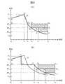
つぎに、図3(A)、(B)を用いて、本実施の形態に係る充電システムの充電パターン(充電器100から電池システム201に供給される充電用電力の変遷)を説明する。ここで、縦軸は電力を示し、横軸は時間を示している。また、Pcapは交直変換部103x(但しx=1〜4)の1台当たりの出力可能電力値である。したがって、出力可能電力総和値は4Pcapとなる。Next, the charging pattern of the charging system according to the present embodiment (transition of charging power supplied from the charger 100 to the battery system 201) will be described with reference to FIGS. Here, the vertical axis indicates power, and the horizontal axis indicates time. Pcap is an outputable power value per unit of the AC / DC converter 103x (where x = 1 to 4). Therefore, the total output power value is 4Pcap .
図3(A)は、本実施の形態に係る充電システムにおいて、出力可能電力総和値4Pcapを超える部分の充電用電力を賄うために必要な電力が蓄電部105に貯蔵されている場合の充電パターン例10を説明するための図である。FIG. 3A shows charging in the charging system according to the present embodiment when electric power necessary to cover the portion of electric power for charging exceeding the total
この充電パターン例10によれば、電池203の充電容量が所定値に到達するまでは(時間t0〜t1)、充電用電力を初期値P0から増加させ、電池203の充電容量が所定値に到達したならば(時間t1)、充電用電力を、そのときの電力値P1から減少させ、電池203の充電容量が目標容量に達したならば(時間t5)、電池システム201から充電停止命令を受信して、充電を終了させる。According to this charging pattern example 10, until the charging capacity of the
ここで、時間t0〜t2において、出力可能電力総和値4Pcapに相当する大きさの充電用電力は、4つの交直変換部1031〜1034により供給され、出力可能電力総和値4Pcapを超える部分の充電用電力(C0A0B1C2で囲まれる領域)は、蓄電部105の貯蔵電力によって賄われる。時間t2以降、充電用電力値が出力可能電力総和値4Pcap以下となるため、蓄電部105の貯蔵電力を用いることなく、4つの交直変換部1031〜1034だけで充電用電力が賄われる。時間t3以降になると、充電用電力値が3Pcap以下となるため、1台の交直変換部1031の出力先が電池システム201から蓄電部105に切り替えられ、その結果、3つの交直変換部1032〜1034だけで充電用電力が賄われるとともに、1台の交直変換部1031により蓄電部105の充電が行われる(D3C3C5D5で囲まれる領域)。さらに時間t4以降になると、充電用電力値が2Pcap以下となるため、さらに1台の交直変換部1032の出力先が電池システム201から蓄電部105に切り替えられ、その結果、2つの交直変換部1033、1034だけで充電用電力が賄われるとともに、2台の交直変換部1031、1032により蓄電部105の充電が行われる(D3C3C5D5およびE4D4D5E5で囲まれる領域)。Here, at time t0 to t2 , charging power having a magnitude corresponding to the output possible power
図3(B)は、本実施の形態に係る充電システムにおいて、出力可能電力総和値4Pcapを超える部分の充電用電力を賄うために必要な電力が蓄電部105に貯蔵されていない場合の充電パターン例11を説明するための図である。FIG. 3B illustrates charging in the charging system according to the present embodiment when power necessary for supplying charging power for a portion exceeding the total
この充電パターン例11によれば、蓄電部105の貯蔵電力を使い切るまでは(時間t0〜t6)、充電用電力を初期値P0から増加させ、蓄電部105の貯蔵電力を使い切ったならば(時間t6)、例えば充電制御部110が電池システム201に充電用電力上限値として出力可能電力総和値4Pcapを通知することで、充電用電力を出力可能電力総和値4Pcap以下に出力制限する。電池203の充電容量が所定値に到達したならば(時間t7)、充電用電力を、そのときの電力値4Pcapから減少させ、電池203の充電容量が目標容量に達したならば(時間t10)、電池システム201から充電停止命令を受信して、充電を終了させる。この充電パターン例11においては、電池203の充電容量が所定値に到達する前に蓄電部105の貯蔵電力を使い切っているため、図3(A)に示す充電パターン例10に比べて、充電終了までの時間が長くなっている(t5<t10)。According to this charging pattern example 11, until the stored power of the
ここで、時間t0〜t6において、出力可能電力総和値4Pcapに相当する大きさの充電用電力は、4つの交直変換部1031〜1034により供給され、出力可能電力総和値4Pcapを超える部分の充電用電力(C0A0F6C6で囲まれる領域)は、蓄電部105の貯蔵電力によって賄われる。蓄電部105の貯蔵電力を使い切った時間t6以降、4つの交直変換部1031〜1034だけで充電用電力が賄われる。時間t8以降になると、充電用電力値が3Pcap以下となるため、1台の交直変換部1031の出力先が電池システム201から蓄電部105に切り替えられ、その結果、3つの交直変換部1032〜1034だけで充電用電力が賄われるとともに、1台の交直変換部1031により蓄電部105の充電が行われる(D8C8C10D10で囲まれる領域)。さらに時間t9以降になると、充電用電力値が2Pcap以下となるため、さらに1台の交直変換部1032の出力先が電池システム201から蓄電部105に切り替えられ、その結果、2つの交直変換部1033、1034だけで充電用電力が賄われるとともに、2台の交直変換部1031、1032により蓄電部105の充電が行われる(D8C8C10D10およびE9D9D10E10で囲まれる領域)。Here, at time t0 to t6 , charging power having a magnitude corresponding to the total output power
以上、本発明の一実施の形態を説明した。 The embodiment of the present invention has been described above.
以上説明したように、本実施の形態によれば、複数台の交直変換部1031〜1034と蓄電部105とを併用して、電池システム201に充電用電力を供給するので、蓄電部105の容量以上の電池203を満充電にすることができる。また、交流電源300を提供する電力事業者との電力契約は、出力可能電力総和値4Pcapに合わせて締結すればよく、電池システム201が要求する充電用電力のピーク値(図3(A)ではP1)に合わせる必要がない。さらに、電池システム201が要求する充電用電力の電力値が3Pcap以下ならば、電池203を充電しながら蓄電部105を充電することができる。したがって、複数の電気自動車200を連続して効率よく、低コストで充電することができる。As described above, according to the present embodiment, since a plurality of AC /
また、本実施の形態において、電池システム201は、図3(A)の充電パターン例10に示すように、充電用電力が、充電前段(時間t0〜t2)において4Pcapより大きくなり、充電中段(時間t2〜t3)において4Pcap以下となり、さらに充電後段(時間t3〜t5)において3Pcap以下となり、さらに2Pcap以下となるように、充電器100に対して指示値を逐次出力する。このため、本実施の形態によれば、充電前段において、蓄電部105の貯蔵電力も利用して電池203を充電し、充電後段において、少なくとも1台の交直変換部103x(但しx=1〜4)を利用して蓄電部105を充電できるので、出力可能電力総和値4Pcapより大きな充電用電力を必要とする電池203でも、連続して効率よく充電できる。Further, in the present embodiment, as shown in the charging pattern example 10 in FIG. 3A, in the present embodiment, the charging power becomes larger than 4Pcap at the pre-charging stage (time t0 to t2 ), in charging the middle (timet 2 ~t3) becomes the following4P cap, becomes more or less3-way cap in the charge later stage (timet 3 ~t5), as further equal to or less than2P cap, indicated value to the charger 100 Are output sequentially. Therefore, according to the present embodiment, the
なお、本発明は上記実施の形態に限定されるものではなく、その要旨の範囲内で数々の変形が可能である。 In addition, this invention is not limited to the said embodiment, Many deformation | transformation are possible within the range of the summary.
例えば、上記実施の形態では、3Pcap以下の充電用電力が必要な場合、4台の交直変換部1031〜1034のうち、一部の交直変換部が出力する直流電力を電池システム201に供給しながら、残りのすべての交直変換部が出力する直流電力を蓄電部105に供給しているが、一部の交直変換部が出力する直流電力を電池システム201に供給しながら、残りの交直変換部のうちの一部の交直変換部が出力する直流電力を蓄電部105に供給するようにしてもよい。For example, in the above embodiment, when the charging power of 3Pcap or less is required, the DC power output from some of the AC /
また、上記実施の形態では、充電後段において充電用電力が単調に減少することを前提としているが、電池システム201から要求される充電用電力の指示値が再び増加した場合に、蓄電部105に直流電力を供給する交直変換部の数を減らして、電池システム201に直流電力を供給する交直変換部の数を増やす制御・運転を行ってもよい。 In the above embodiment, it is assumed that the charging power decreases monotonously in the latter stage of charging. However, when the instruction value of the charging power required from the
さらに、上記実施の形態では、交直変換部1031〜1034の数を4台としているが、本発明はこれに限定されない。n(但しn≧2)台の交直変換部1031〜103nと蓄電部105とを併用して、電池システム201に充電用電力を供給するものであればよい。そして、出力可能電力総和値nPcapより大きな充電用電力が必要な場合に、これらのn台の交直変換部1031〜103nが出力する直流電力に、蓄電部105に貯蔵された直流電力を加算して、電池システム201に供給し、mPcap(但しm<n)以下の充電用電力が必要な場合に、n台の交直変換部1031〜103nのうち、m台の交直変換部を選択して、選択されたm台の交直変換部が出力する直流電力を電池システム201に供給する一方、選択されなかった交直変換部103の少なくとも1台が出力する直流電力を蓄電部105に供給し、電池203を充電しながら蓄電部105を充電するものであればよい。Furthermore, in the said embodiment, although the number of AC / DC conversion part 1031 -1034 is four units, this invention is not limited to this. Any combination of n (where n ≧ 2) AC /
また、上記実施の形態では、充電器100が電池システム201から逐次通知される指示値に従い、電池システム201に供給する充電用電力を制御する場合を例にとり説明した。しかし、本発明はこれに限定されない。例えば、充電器100が、充電開始に先だって電池システム201から通知された充電モードあるいは充電パターンに従い、電池システム201に供給する充電用電力を制御する場合、および、充電器100が、電池システム201に供給する充電用電力を自律的に制御する場合にも、本発明を適用できる。 In the above embodiment, the case where the charger 100 controls the charging power supplied to the
また、上記実施の形態では、電気自動車200に搭載された電池(車両駆動用バッテリ)203を充電する場合を例にとり説明したが、本発明は、電気自動車200のみならず、搭載されたバッテリを外部電源から充電する機能を有する電動車両等の電動移動体にも広く適用できる。 In the above embodiment, the case where the battery (vehicle driving battery) 203 mounted on the
100:充電器、101:充電ケーブル、102:充電器側コネクタ、1031〜1034:交直変換部、1041〜1044:ダイオード、105:蓄電部、106:電圧調整部、107:ダイオード、108:セレクタ、109:ELB、110:充電制御部、111:充電用ライン、112:通信用ライン、1131〜1135:リレー、200:電気自動車、201:電池システム、202:車両側コネクタ、203:電池、300:交流電源100: Charger, 101: charging cable, 102: charger-
Claims (3)
Translated fromJapanese交流電力を直流電力に変換するn(但しn≧2)台の交直変換手段と、
直流電力を貯蔵する蓄電手段と、
前記交直変換手段各々の出力先を前記充電用ラインおよび前記蓄電手段のいずれか一方に切り替える切替手段と、
前記切替手段および前記蓄電手段を制御して、前記充電用電力を前記充電用ラインに供給する充電制御手段と、を有し、
前記充電制御手段は、
前記充電用電力が、n台の前記交直変換手段が出力可能な直流電力の総和より大きい場合に、すべての前記交直変換手段の出力先を前記充電用ラインに設定するとともに、前記蓄電手段に貯蔵された直流電力を前記充電用ラインに出力させ、
前記充電用電力が、m台(但しm<n)の前記交直変換手段が出力可能な直流電力の総和以下である場合に、m台の前記交直変換手段の出力先を前記充電用ラインに設定するとともに、当該m台の交直変換手段以外の少なくとも1台の前記交直変換手段の出力先を前記蓄電手段に設定して前記蓄電手段に直流電力を供給する
ことを特徴とする充電器。A charger that supplies electric power for charging to an electric vehicle via a charging line,
N (where n ≧ 2) AC / DC converting means for converting AC power to DC power;
Power storage means for storing DC power;
Switching means for switching the output destination of each of the AC / DC converting means to either the charging line or the power storage means;
Charging control means for controlling the switching means and the power storage means to supply the charging power to the charging line;
The charge control means includes
When the charging power is larger than the sum of direct-current power that can be output from the n AC / DC converting means, the output destinations of all the AC / DC converting means are set to the charging line and stored in the power storage means. Output the direct current power to the charging line,
When the charging power is equal to or less than the sum of the DC power that can be output by the m (where m <n) AC / DC converters, the output destination of the m AC / DC converters is set to the charging line In addition, the charger is characterized in that an output destination of at least one of the AC / DC conversion means other than the m AC / DC conversion means is set to the power storage means and DC power is supplied to the power storage means.
前記充電器は、
交流電力を直流電力に変換するn(但しn≧2)台の交直変換手段と、
直流電力を貯蔵する蓄電手段と、を有し、
前記充電用電力が、n台の前記交直変換手段が出力可能な直流電力の総和より大きいならば、すべての前記交直変換手段が出力する直流電力に、前記蓄電手段に貯蔵された直流電力を加算して、当該加算された直流電力を前記充電用電力として前記電動移動体に供給し、
前記充電用電力が、m(但しm<n)台の前記交直変換手段が出力する直流電力の総和以下であるならば、m台の前記交直変換手段が出力する直流電力を加算して、当該加算された直流電力を前記充電用電力として前記電動移動体に供給する一方、当該m台の交直変換手段以外の少なくとも1台の前記交直変換手段が出力する直流電力を前記蓄電手段に供給して、前記蓄電手段を充電する
ことを特徴とする電動移動体用バッテリの充電方法。A method of charging a battery for an electric vehicle that supplies electric power for charging to the electric vehicle using a charger,
The charger is
N (where n ≧ 2) AC / DC converting means for converting AC power to DC power;
Power storage means for storing DC power,
If the charging power is greater than the sum of the DC powers that can be output by the n AC / DC converting means, the DC power stored in the power storage means is added to the DC power output by all the AC / DC converting means. Then, the added DC power is supplied to the electric vehicle as the charging power,
If the charging power is less than or equal to the sum of the DC power output by the m (where m <n) AC / DC converters, add the DC power output by the m AC / DC converters, The added DC power is supplied to the electric vehicle as the charging power, while the DC power output from at least one AC / DC converting unit other than the m AC / DC converting units is supplied to the power storage unit. And charging the power storage means. A method for charging a battery for an electric vehicle.
充電前段において、n台の前記交直変換手段が出力可能な直流電力の総和より大きくなり、充電後段において、m台の前記交直変換手段が出力する直流電力の総和以下となるように、前記充電用電力が制御される
ことを特徴とする電動移動体用バッテリの充電方法。It is a charging method of the battery for electric vehicles according to claim 2,
In the pre-charging stage, the charging power is set to be larger than the sum of the direct-current powers that can be output by the n AC / DC conversion units, and to be equal to or less than the total DC power output from the m AC / DC conversion units in the post-charging stage. A method for charging a battery for an electric vehicle, wherein the electric power is controlled.
Priority Applications (1)
| Application Number | Priority Date | Filing Date | Title |
|---|---|---|---|
| JP2010164577AJP2012029424A (en) | 2010-07-22 | 2010-07-22 | Battery charger and method of charging battery for motor-driven moving body |
Applications Claiming Priority (1)
| Application Number | Priority Date | Filing Date | Title |
|---|---|---|---|
| JP2010164577AJP2012029424A (en) | 2010-07-22 | 2010-07-22 | Battery charger and method of charging battery for motor-driven moving body |
Publications (1)
| Publication Number | Publication Date |
|---|---|
| JP2012029424Atrue JP2012029424A (en) | 2012-02-09 |
Family
ID=45781715
Family Applications (1)
| Application Number | Title | Priority Date | Filing Date |
|---|---|---|---|
| JP2010164577APendingJP2012029424A (en) | 2010-07-22 | 2010-07-22 | Battery charger and method of charging battery for motor-driven moving body |
Country Status (1)
| Country | Link |
|---|---|
| JP (1) | JP2012029424A (en) |
Cited By (3)
| Publication number | Priority date | Publication date | Assignee | Title |
|---|---|---|---|---|
| JP2015517292A (en)* | 2012-04-03 | 2015-06-18 | エンリッチメント テクノロジー カンパニー エルディーティー.Enrichment Technology Company Ldt. | Electric vehicle charging facility with quick charging station |
| CN105978076A (en)* | 2016-06-08 | 2016-09-28 | 辛建宏 | Mobile electric automobile endurance charging device |
| CN109572454A (en)* | 2018-10-17 | 2019-04-05 | 国网浙江省电力有限公司杭州供电公司 | A kind of electric car Intelligent charging station charging system |
- 2010
- 2010-07-22JPJP2010164577Apatent/JP2012029424A/enactivePending
Cited By (3)
| Publication number | Priority date | Publication date | Assignee | Title |
|---|---|---|---|---|
| JP2015517292A (en)* | 2012-04-03 | 2015-06-18 | エンリッチメント テクノロジー カンパニー エルディーティー.Enrichment Technology Company Ldt. | Electric vehicle charging facility with quick charging station |
| CN105978076A (en)* | 2016-06-08 | 2016-09-28 | 辛建宏 | Mobile electric automobile endurance charging device |
| CN109572454A (en)* | 2018-10-17 | 2019-04-05 | 国网浙江省电力有限公司杭州供电公司 | A kind of electric car Intelligent charging station charging system |
Similar Documents
| Publication | Publication Date | Title |
|---|---|---|
| JP6832751B2 (en) | Charge transfer management method and charge transfer device | |
| JP4954335B2 (en) | Quick charger | |
| JP5616500B2 (en) | Charging device and operation method thereof | |
| JP5649440B2 (en) | Power control system | |
| CN115036951A (en) | Energy storage system and battery management method | |
| WO2013076951A1 (en) | Power converter | |
| JP6183709B2 (en) | Electric vehicle charging / discharging system | |
| US9876391B2 (en) | Power conversion apparatus, control system, and control method | |
| WO2014174808A1 (en) | Power supply system | |
| CN102630361A (en) | Power conversion apparatus, power generating system, and charge/discharge control method | |
| KR101330349B1 (en) | Apparatus and method for power conversion | |
| JP2014023426A (en) | Battery charging apparatus and battery charging method thereof | |
| US9748796B2 (en) | Multi-port energy storage system and control method thereof | |
| JP6876992B2 (en) | Vehicle power supply | |
| US9425717B2 (en) | Device and method for supplying an electric drive with electric current | |
| KR20180136177A (en) | An energy storage system | |
| EP3333009B1 (en) | System for re-charging an accumulator of energy of an electric vehicle (ev) | |
| JP2016025797A (en) | Power control device and power storage device | |
| JP2012029424A (en) | Battery charger and method of charging battery for motor-driven moving body | |
| KR20180099279A (en) | Energy storage system including energy storage device | |
| JP5993082B1 (en) | Distributed power system, power conversion device, and power factor control method | |
| CN113423604A (en) | Device, method and cable for feeding electrical energy into an energy network based on a mobile energy store | |
| WO2023194859A1 (en) | Electric vehicle charger and network of electric vehicle chargers | |
| JP6050914B1 (en) | Distributed power system and power converter | |
| EP3859934A1 (en) | Control method for electric vehicle and electric vehicle system |