JP2012029045A - Image compositing device, image compositing method and program - Google Patents
Image compositing device, image compositing method and programDownload PDFInfo
- Publication number
- JP2012029045A JP2012029045AJP2010165968AJP2010165968AJP2012029045AJP 2012029045 AJP2012029045 AJP 2012029045AJP 2010165968 AJP2010165968 AJP 2010165968AJP 2010165968 AJP2010165968 AJP 2010165968AJP 2012029045 AJP2012029045 AJP 2012029045A
- Authority
- JP
- Japan
- Prior art keywords
- image
- difference
- images
- unit
- acquired
- Prior art date
- Legal status (The legal status is an assumption and is not a legal conclusion. Google has not performed a legal analysis and makes no representation as to the accuracy of the status listed.)
- Granted
Links
Images


Landscapes
- Image Processing (AREA)
- Editing Of Facsimile Originals (AREA)
- Studio Devices (AREA)
Abstract
Translated fromJapaneseDescription
Translated fromJapanese本発明は、画像合成装置、画像合成方法、及びプログラムに関する。 The present invention relates to an image composition device, an image composition method, and a program.
従来より、連写された画像を画素加算合成することにより、夜景等、光量の少ない撮影環境であっても、記録するのに十分な明るさを有する画像を生成する技術が知られている。
また、特許文献1に記載されるように、カメラをユーザが手に持って撮影する手持ち撮影の際、撮像画角のブレを補正し合成する画像合成技術も知られている。2. Description of the Related Art Conventionally, a technique for generating an image having sufficient brightness for recording even in a shooting environment with a small amount of light, such as a night view, by adding and synthesizing continuously shot images is known.
Also, as described in Patent Document 1, there is also known an image composition technique that corrects and synthesizes an imaging angle of view when performing hand-held shooting in which a user holds a camera in his / her hand.
しかしながら上記の画像合成技術の場合、効果を奏するのは撮影画角に対し主要被写体が動いていない、つまり動体が存在しないケースに限られる。
すなわち、動体が存在しないケースでは、手持ち撮影による撮像画角のブレを補正し合成することにより、撮像画角全体について手ブレの影響が少ない画像を取得することが可能となる。しかし、動体が存在するケースではこの限りではなく、上記画像合成技術を用いても動体の残像が残る画像が取得されることになる。However, in the case of the above image composition technique, the effect is limited to the case where the main subject does not move with respect to the shooting angle of view, that is, there is no moving object.
That is, in the case where there is no moving object, it is possible to acquire an image with less influence of camera shake for the entire imaging field angle by correcting and synthesizing the imaging field angle blur due to hand-held shooting. However, this is not the case in the case where a moving object exists, and an image in which an afterimage of the moving object remains is acquired even if the above-described image composition technique is used.
本発明は、かかる従来の課題に鑑みてなされたものであり、撮影画角に動体が存在する場合においても動体の残像の影響が少ない合成画像を得ることができるようにすることを目的とするものである。 The present invention has been made in view of such conventional problems, and an object of the present invention is to provide a composite image that is less affected by the afterimage of the moving object even when the moving object exists at the shooting angle of view. Is.
前記課題を解決するために請求項1記載の発明は、時間的に連続する複数の画像を取得する画像取得手段と、この画像取得手段によって取得された複数の画像から、合成の基準となる基準画像を選択する選択手段と、前記画像取得手段によって取得された複数の画像を画素加算合成して一つの画像を生成する画像生成手段と、前記選択手段によって選択された基準画像と前記画像取得手段によって取得された他の画像との画素毎の差分の最大値を、前記他の画像毎に取得する差分取得手段と、この差分取得手段によって取得された情報を平均化し、これを透過強度の情報として前記画像生成手段により生成された画像にブレンディングするブレンディング手段とを備えたことを特徴とする。 In order to solve the above-mentioned problem, the invention according to claim 1 is characterized in that an image acquisition unit that acquires a plurality of temporally continuous images and a reference that is a reference for synthesis from the plurality of images acquired by the image acquisition unit. A selection unit for selecting an image; an image generation unit for generating a single image by adding and synthesizing a plurality of images acquired by the image acquisition unit; a reference image selected by the selection unit; and the image acquisition unit The difference acquisition means for acquiring the maximum value of the difference for each pixel from the other image acquired by each other image, and the information acquired by the difference acquisition means are averaged, and this is transmitted intensity information. And blending means for blending the image generated by the image generating means.
また、請求項2記載の発明は、請求項1記載の発明において、前記ブレンディング手段は、前記差分取得手段によって取得された情報を平均化し、この平均化された情報に基づいて更にコントラストを上げる処理を実行することを特徴とする。 The invention according to claim 2 is the processing according to claim 1, wherein the blending means averages the information acquired by the difference acquisition means, and further increases the contrast based on the averaged information. It is characterized by performing.
また、請求項3記載の発明は、請求項1又は2記載の発明において、前記ブレンディング手段は、前記差分取得手段によって取得された情報を平均化し、これ平均化された情報に基づいて更に平滑化処理を実行することを特徴とする。 Further, the invention according to claim 3 is the invention according to claim 1 or 2, wherein the blending means averages the information acquired by the difference acquisition means, and further smoothes based on the averaged information. A process is executed.
また、請求項4記載の発明は、請求項1乃至3の何れか記載の発明において、前記画像取得手段は、撮像手段を含むことを特徴とする。 The invention according to claim 4 is the invention according to any one of claims 1 to 3, wherein the image acquisition means includes an imaging means.
また、請求項5記載の発明は、請求項1乃至4の何れか記載の発明において、前記画像とは、略同じ撮像画角で取得されたものであることを特徴とする。 The invention according to claim 5 is characterized in that, in the invention according to any one of claims 1 to 4, the image is acquired at substantially the same imaging angle of view.
また、請求項6記載の発明は、時間的に連続する複数の画像を取得する画像取得ステップと、この画像取得ステップによって取得された複数の画像から、合成の基準となる基準画像を選択する選択ステップと、前記画像取得ステップによって取得された複数の画像を画素加算合成して一つの画像を生成する画像生成ステップと、前記選択ステップによって選択された基準画像と前記画像取得ステップによって取得された他の画像との画素毎の差分の最大値を、前記他の画像毎に取得する差分取得ステップと、この差分取得ステップによって取得された情報を平均化し、これを透過強度の情報として前記画像生成ステップにより生成された画像にブレンディングするブレンディングステップとを含むことを特徴とする。 The invention according to claim 6 is an image acquisition step for acquiring a plurality of temporally continuous images, and a selection for selecting a reference image as a reference for synthesis from the plurality of images acquired by the image acquisition step. An image generation step for generating a single image by adding and synthesizing a plurality of images acquired by the image acquisition step, a reference image selected by the selection step, and another acquired by the image acquisition step The difference acquisition step of acquiring the maximum value of the difference for each pixel from the image of each other image, the information acquired by the difference acquisition step is averaged, and this is used as transmission intensity information for the image generation step And a blending step for blending the image generated by.
また、請求項7記載の発明は、装置が有するコンピュータを、時間的に連続する複数の画像を取得する画像取得手段、この画像取得手段によって取得された複数の画像から、合成の基準となる基準画像を選択する選択手段、前記画像取得手段によって取得された複数の画像を画素加算合成して一つの画像を生成する画像生成手段、前記選択手段によって選択された基準画像と前記画像取得手段によって取得された他の画像との画素毎の差分の最大値を、前記他の画像毎に取得する差分取得手段、この差分取得手段によって取得された情報を平均化し、これを透過強度の情報として前記画像生成手段により生成された画像にブレンディングするブレンディング手段として機能させることを特徴とする。 According to a seventh aspect of the present invention, there is provided an image acquisition unit that acquires a plurality of temporally continuous images from a computer included in the apparatus, and a reference that is a reference for synthesis from the plurality of images acquired by the image acquisition unit. Selection means for selecting an image, image generation means for generating a single image by adding and synthesizing a plurality of images acquired by the image acquisition means, a reference image selected by the selection means, and acquisition by the image acquisition means The difference acquisition means for acquiring the maximum value of the difference for each pixel from the other image thus obtained for each of the other images, the information acquired by the difference acquisition means is averaged, and this is used as transmission intensity information for the image. It is characterized by functioning as a blending means for blending the image generated by the generating means.
本発明によれば、撮影画角に動体が存在する場合においても動体の残像の影響が少ない合成画像を得ることができる。 According to the present invention, it is possible to obtain a composite image that is less affected by an afterimage of a moving object even when the moving object exists at the shooting angle of view.
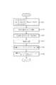
以下、本発明の一実施の形態を図に従って説明する。図1は、本発明の一実施の形態に係る画像処理装置を備える撮像装置の回路構成図である。この撮像装置は、撮像部1、駆動制御部2、CDS/ADC3、キー入力部4、表示部5、画像記録部6、プログラムメモリ7、RAM8、制御部9、画像処理部10を有している。これらは、バスラインを介して接続されている。キー入力部4は撮影者の記録指示を検出するためのシャッターキー41を備え、画像処理部10は合成部11を備える。 Hereinafter, an embodiment of the present invention will be described with reference to the drawings. FIG. 1 is a circuit configuration diagram of an imaging apparatus including an image processing apparatus according to an embodiment of the present invention. The imaging apparatus includes an imaging unit 1, a drive control unit 2, a CDS / ADC 3, a key input unit 4, a display unit 5, an image recording unit 6, a program memory 7, a RAM 8, a
同図において撮像部1は、CMOS等のイメージセンサ、このイメージセンサ上に設けられたRGBのカラーフィルタ、及び、駆動制御部2からの制御により、光の強度を電荷の蓄積として一定時間保持し、CDS/ADC3にアナログの撮像信号としてこれらを出力するドライバを内蔵する。そして、シャッターキー41、制御部9、駆動制御部2を経由した撮影者の撮影指示を検出することで、複数の画像(カラー画像)を取得する。 In the figure, the imaging unit 1 holds the light intensity as a charge accumulation for a certain period of time by controlling from an image sensor such as a CMOS, an RGB color filter provided on the image sensor, and the drive control unit 2. The CDS / ADC 3 includes a driver that outputs these as analog imaging signals. A plurality of images (color images) are acquired by detecting a photographing instruction of the photographer via the
CDS/ADC3は、撮像部1から出力される被写体の光学像に応じたアナログの撮像信号が入力される回路であって、入力した撮像信号を保持するCDSと、その撮像信号を増幅するゲイン調整アンプ(AGC)、増幅された撮像信号をデジタルの撮像信号に変換するA/D変換器(ADC)等から構成される。なお、ゲイン調整アンプの調整に関わる制御についても、駆動制御部2からの指示に基づき行われる。このため、露光条件(シャッタースピード、若しくは絞り値)を同じくして複数枚の画像を取得しても、RGBのゲイン調整アンプや画像の色味を順次変えることによる条件の異なる複数の画像を生成することができる。 The CDS / ADC 3 is a circuit to which an analog imaging signal corresponding to the optical image of the subject output from the imaging unit 1 is input. The CDS / ADC 3 holds the input imaging signal and gain adjustment for amplifying the imaging signal. An amplifier (AGC), an A / D converter (ADC) that converts the amplified imaging signal into a digital imaging signal, and the like are configured. Control related to the adjustment of the gain adjustment amplifier is also performed based on an instruction from the drive control unit 2. Therefore, even if multiple images are acquired with the same exposure conditions (shutter speed or aperture value), multiple images with different conditions can be generated by sequentially changing the RGB gain adjustment amplifier and the color of the image. can do.
尚、本実施の形態においては、駆動制御部2がゲイン調整アンプに関わる制御を行なうようにしたが、これに限らない。例えば上記の制御は制御部9で行なうようにしてもよい。 In the present embodiment, the drive control unit 2 performs control related to the gain adjustment amplifier. However, the present invention is not limited to this. For example, the above control may be performed by the
キー入力部4は、上述のシャッターキー41の他、本発明に係る画像の取得・記録を目的すとする撮影モードへの切り換え、表示の切り換え等を検出するための各種キーを備える。 In addition to the
表示部5は、合成された画像を表示する機能を有する。画像記録部6は、本発明に係る合成処理が実行された後、JPEG方式で符号化された画像データ(画像ファイル)を記憶・格納する。プログラムメモリ7は、制御部9、画像処理部10にて実行されるプログラムを記憶し、このプログラムは必要に応じて制御部9が読み出す。RAM8は、各処理により発生する処理中のデータを一時的に保持する機能を有する。制御部9は、この撮像装置全体の処理動作を制御する。画像処理部10は、画像データの符号化/復号化処理の他、本発明の特徴的構成に対応する合成部11を備える。 The display unit 5 has a function of displaying the synthesized image. The image recording unit 6 stores and stores image data (image file) encoded by the JPEG method after the composition processing according to the present invention is executed. The program memory 7 stores a program executed by the
すなわち合成部11は、連写画像から選択された1枚の基準画像と、連写画像を加算合成した合成画像との合成を実行するとともに、この合成画像について後述する動体判定マップを差分領域に対応する透過強度マップ(αマップ)として用いて動体による残像を少なくさせるものである。 That is, the synthesizing
次に、本実施の形態の動作について説明する。ユーザがキー入力部4に設けられているモードボタンを操作して、本実施形態に係る撮影モードを設定すると、制御部9がプログラムメモリ7からプログラムを読み出して、図2のフローチャートに示すように、処理を開始する。 Next, the operation of the present embodiment will be described. When the user operates the mode button provided in the key input unit 4 to set the shooting mode according to the present embodiment, the
すなわち、制御部9はシャッターキー41の押下が検出されたか否かを判断する(ステップS101)。シャッターキー41の押下が検出されたならば、駆動制御部2に指示してN枚の連写を実行させる(ステップS102)。引き続き、連写により得られた画像データに基づき、輝度色差の色空間情報で表現されたYUV画像からなる連写画像を生成してRAM8に保存する(ステップS103)。 That is, the
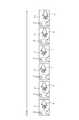
したがって、連写枚数Nが例えば6枚であったとすると、図4に示すように、YUV画像からなる6枚の連写画像P1〜P6がRAM8に保存される。図4において矢印tは、時間軸であり、連写画像P1〜P6は、撮像画角全体をしめす背景B内において動体としての手Hを上下に振っている状態で、略同じ撮像画角で連写したものである。連写画像P1〜P6において、背景Bは同一であるが、P1→P2→P3と時間tが進むに従って手Hの像は背景B内において相対的に上の位置にあり、画像P3の手Hの像は最も上に位置する。また、P3→P4→P5→P6と時間tが進むに従って手Hの像は背景B内において相対的に下の位置にあり、画像P6の手Hの像は最も下に位置する。 Therefore, if the number N of continuous shots is 6, for example, six continuous shot images P1 to P6 made of YUV images are stored in the RAM 8 as shown in FIG. In FIG. 4, the arrow t is a time axis, and the continuous shot images P1 to P6 have substantially the same imaging field angle in a state where the hand H as a moving object is shaken up and down in the background B indicating the entire imaging field angle. It is a continuous shot. In the continuous shot images P1 to P6, the background B is the same, but the image of the hand H is relatively higher in the background B as the time t advances from P1 → P2 → P3, and the hand H of the image P3 The image of is located on the top. Further, as the time t advances from P3 → P4 → P5 → P6, the image of the hand H is at a relatively lower position in the background B, and the image of the hand H in the image P6 is positioned at the lowest position.
なお、これら連写画像P1〜P6の連写に際しては、手ブレによる画像のブレは公知の技術(CCDシフトやレンズシフトによる画角補正技術)により補正されているものとする。しかし、各連写画像P1〜P6中の手Hの像は動体ブレの要因とされる。 In the continuous shooting of these continuous shot images P1 to P6, it is assumed that image blur due to camera shake is corrected by a known technique (view angle correction technique using CCD shift or lens shift). However, the image of the hand H in each of the continuous shot images P1 to P6 is considered to be a cause of motion blur.
次に、これら連写画像から基準画像を選択する(ステップS104)。この基準画像の選択に際しては、連写画像の中で動体の動き量が最も小さい画像選択する。したがって、連写画像P1〜P6において、動体(手Hの像)の動き量が最も小さい画像は下方向から上方向に動いた手Hの像が上方向から下方向に変化する分岐点の画像、つまり手Hの像の位置が背景Bに対し相対的に最も上にある連写画像P3である。よって、この例では連写画像P3を基準画像として選択する。 Next, a reference image is selected from these continuous shot images (step S104). When selecting the reference image, an image with the smallest amount of motion of the moving object is selected from the continuous shot images. Therefore, in the continuous shot images P1 to P6, the image with the smallest amount of motion of the moving object (the image of the hand H) is the image of the branch point where the image of the hand H that has moved from the lower direction to the upper direction changes from the upper direction to the lower direction. That is, it is the continuous shot image P3 in which the position of the image of the hand H is the uppermost relative to the background B. Therefore, in this example, the continuous shot image P3 is selected as the reference image.
しかる後に、この選択した基準画像の画像データをLPF(ローパスフィルタ)にて透過処理する等により、ノイズ低減処理する(ステップS105)。そして、このノイズ低減処理した基準画像のYUV画像データをRAM8に一旦保存する(ステップS106)。したがって、このステップS105及びステップS106での処理により、図4に示した例においては、連写画像P3の画像データがノイズ低減処理されて、そのYUV画像データがRAM8に保存されることとなる。 Thereafter, noise reduction processing is performed by, for example, performing transmission processing on the image data of the selected reference image with an LPF (low-pass filter) (step S105). Then, the YUV image data of the reference image subjected to the noise reduction process is temporarily stored in the RAM 8 (step S106). Therefore, in the example shown in FIG. 4, the image data of the continuous shot image P <b> 3 is subjected to noise reduction processing and the YUV image data is stored in the RAM 8 by the processing in steps S <b> 105 and S <b> 106.
また、連写された複数枚の画像に関しては、ノイズ低減し合成する(ステップS107)。つまり、複数枚の連写画像のYUV画像データを画素毎に加算平均すれば、ノイズ低減しつつ合成を行うことができる。複数枚Nの連写画像のYUV画像データ加算平均の式[1]〜[3]を下記に示す。尚、Y_result、 U_result、 及び、V_resultは、画素の輝度色差パラメータ夫々の合成後の情報を示すものである。
Y_result = (Y[0] + Y[1] + ・・・ + Y [N]) / N ・・・式[1]
U_result = (U[0] + U[1] + ・・・ + U [N]) / N ・・・式[2]
V_result = (V[0] + V[1] + ・・・ + V [N]) / N ・・・式[3]Further, the plurality of continuously shot images are reduced and combined (step S107). That is, by averaging the YUV image data of a plurality of continuous shot images for each pixel, it is possible to perform synthesis while reducing noise. Expressions [1] to [3] for averaging the YUV image data of a plurality of N continuous shot images are shown below. Y_result, U_result, and V_result indicate information after combining the luminance color difference parameters of the pixels.
Y_result = (Y [0] + Y [1] + ... + Y [N]) / N ... expression [1]
U_result = (U [0] + U [1] + ... + U [N]) / N ... expression [2]
V_result = (V [0] + V [1] + ... + V [N]) / N ... Formula [3]
無論、複数枚の連写画像を用いたノイズ低減効果のある合成方法であれば、加算平均に限らず他の処理方法であってもよい。そして、このノイズ低減した全連写画像の合成画像のYUV画像データをRAM8に一旦保存する(ステップS108)。 Of course, as long as it is a synthesis method having a noise reduction effect using a plurality of continuous shot images, other processing methods are not limited to the averaging. Then, the YUV image data of the composite image of all the continuous shots with reduced noise is temporarily stored in the RAM 8 (step S108).
したがって、このステップS108の処理を終了した時点において、RAM8には下記の画像データが一旦保存されることとなる。
(1)各連写画像のYUV画像データ
(2)ノイズ低減処理後の基準画像のYUV画像データ
(3)ノイズ低減処理後の合成画像のYUV画像データTherefore, when the processing of step S108 is completed, the following image data is temporarily stored in the RAM 8.
(1) YUV image data of each continuous shot image (2) YUV image data of a reference image after noise reduction processing (3) YUV image data of a composite image after noise reduction processing
そして、前記(2)基準画像のYUV画像データと、(3)合成画像のYUV画像データとを合成するための処理を次ステップS109の動体判定・αブレンディング処理を含ませて行う。 Then, the process for synthesizing (2) the YUV image data of the reference image and (3) the YUV image data of the synthesized image is performed including the moving object determination / α blending process in the next step S109.
図3は、動体判定・αブレンディング処理(ステップS109)の処理手順を示すフローチャートである。なお、この図3に示すフローチャートの説明に際しては、下記の式、符号あるいは関数を用いる。
Y_Base_Nr, U_Base_Nr, V_Base_Nr :上記(2)のノイズ低減後基準画像データのYUV各パラメータ
Y[n], U[n], V[n] :n枚目の画像データのYUV各パラメータ
N :合成枚数
fMax() :最大値算出関数
fLpf() :平滑化関数
fEmphasis() :マップ強調関数FIG. 3 is a flowchart showing a processing procedure of the moving object determination / α blending process (step S109). In the description of the flowchart shown in FIG. 3, the following equations, symbols, or functions are used.
Y_Base_Nr, U_Base_Nr, V_Base_Nr: YUV parameters of reference image data after noise reduction in (2) above
Y [n], U [n], V [n]: YUV parameters of the nth image data
N: Number of composites
fMax (): Maximum value calculation function
fLpf (): smoothing function
fEmphasis (): Map enhancement function
図3のフローチャートにおいて、制御部9はノイズ低減処理後の基準画像のYUV画像データ(2)と、各連写画像のYUV画像データ(1)との差分絶対値を、下記式[4]〜[6]に示すように、各連写画像のYUV画像データ(1)の画素毎に求める(ステップS201)。
つまり、
Diff_Y[n] = |Y_base_Nr −Y[n]| ・・・式[4] // Yの差分絶対値
Diff_U[n] = |U_base_Nr −U[n]| ・・・式[5] // Uの差分絶対値
Diff_V[n] = |V_base_Nr −V[n]| ・・・式[6] // Vの差分絶対値
を各連写画像の画素毎に求める。In the flowchart of FIG. 3, the
In other words,
Diff_Y [n] = | Y_base_Nr −Y [n] | Expression [4] // Difference absolute value of Y
Diff_U [n] = | U_base_Nr −U [n] | Equation [5] // Absolute difference of U
Diff_V [n] = | V_base_Nr−V [n] | Formula [6] // Absolute absolute value of V is obtained for each pixel of each continuous shot image.
そして、差分が大きいほど、被写体が動いた可能性が高い領域であるといえるから、下記式[7]に示すように差分が最大のもの(連写画像の対応する画素毎に差分が最大のもの)を選択する(ステップS202)。
Diff[n] = fMax(Diff_Y[n], Diff_U[n], Diff_V[n]) ・・・式[7]The larger the difference, the higher the possibility that the subject has moved. Therefore, as shown in the following formula [7], the difference is the largest (the difference is the largest for each corresponding pixel of the continuous shot image). A thing) is selected (step S202).
Diff [n] = fMax (Diff_Y [n], Diff_U [n], Diff_V [n]) Equation [7]
次に、下記式[8]で示すように、基準画像を除く各連写画像の最大差分を平均化する処理を実行する(ステップS203)。
Ave_Diff = (Diff[0] + Diff[1] + ・・・ + Diff[N]) / N-1 ・・・式[8]Next, as shown by the following equation [8], a process of averaging the maximum differences of the continuous shot images excluding the reference image is executed (step S203).
Ave_Diff = (Diff [0] + Diff [1] + ... + Diff [N]) / N-1 ... Equation [8]
更に、下記式[9]で示すように、平滑化処理を実行する(ステップS204)。
Ave_Diff_Lpf = fLpf(Ave_Diff) ・・・式[9]
このステップS204での平滑化処理により、図5(a)に示すように、動体判定マップMが生成されることとなる。この動体判定マップMにおいて、斜線で示した部分は、α=0であって全透過させる領域であり、白抜き部分は、α=255であって不透過とする領域である。Furthermore, as shown by the following formula [9], a smoothing process is executed (step S204).
Ave_Diff_Lpf = fLpf (Ave_Diff) (9)
As a result of the smoothing process in step S204, a moving object determination map M is generated as shown in FIG. In this moving object determination map M, the hatched portion is a region where α = 0 and is totally transmitted, and the white portion is a region where α = 255 and is not transmitted.
引き続き、下記式[10]で示すように、強調処理を行って前記動体判定マップMのコントラストをアップさせる(ステップS105)。
Map_Move = fEmphasis (Ave_Diff_Lpf) ・・・式[10]
このステップS205での平滑化処理により、図5(b)に示すように、動体判定マップMにおいて動体の手Hの像が重なる領域のコントラストがアップされる。Subsequently, as shown by the following equation [10], enhancement processing is performed to increase the contrast of the moving object determination map M (step S105).
Map_Move = fEmphasis (Ave_Diff_Lpf) Expression [10]
By the smoothing process in step S205, as shown in FIG. 5B, the contrast of the area where the image of the moving hand H overlaps in the moving object determination map M is increased.
そして、最終的にこの図5(b)に示した動体判定マップM((Map_ Move [0 ~ 255]: 0=動体なし)をαマップとして用いて、前述した
(2)ノイズ低減処理後の基準画像のYUV画像データ
(3)ノイズ低減処理後の合成画像のYUV画像データ
を合成する(ステップS206)。
合成された各画素のYUVの各パラメータ(Y_result,U_result,V_result)は下記式[11]〜[13]で表現される。
Y_result = (Y_Nr_Mix ×(255−Map_Move) + Y_Base_Nr × Map_ Move) / 255
・・・式[11]
U_result = (U_Nr_Mix ×(255−Map_Move) + U _Base_Nr × Map_ Move) / 255
・・・式[12]
V_result = (V_Nr_Mix ×(255−Map_Move) + V _Base_Nr × Map_ Move) / 255
・・・式[13]
これにより、図6(b)に示すように、背景Bと手Hとからなる合成画像PMを表すYUV画像データが生成されることとなる。Finally, using the moving object determination map M ((Map_Move [0 to 255]: 0 = no moving object) shown in FIG. 5B as the α map, the (2) after the noise reduction processing described above is performed. YUV image data of reference image (3) YUV image data of a synthesized image after noise reduction processing is synthesized (step S206).
Each YUV parameter (Y_result, U_result, V_result) of each synthesized pixel is expressed by the following equations [11] to [13].
Y_result = (Y_Nr_Mix × (255−Map_Move) + Y_Base_Nr × Map_Move) / 255
... Formula [11]
U_result = (U_Nr_Mix × (255−Map_Move) + U _Base_Nr × Map_ Move) / 255
... Formula [12]
V_result = (V_Nr_Mix × (255−Map_Move) + V _Base_Nr × Map_ Move) / 255
... Formula [13]
Thereby, as shown in FIG. 6B, YUV image data representing the composite image PM composed of the background B and the hand H is generated.
ここで、図6(a)は、連写された画像を単に平均加算処理した合成画像PNである。このように、連写された画像を単に平均加算処理した合成画像PNにあっては、動体像である手Hの像に大きなブレが生じてしまう。これに対し、本実施の形態によれば、手Hの像が動いている場合においても、図6(b)に示すように、動体ブレの少ない合成画像PMを得ることができる。 Here, FIG. 6A is a composite image PN obtained by simply averaging the continuously shot images. As described above, in the composite image PN obtained by simply averaging the continuously shot images, a large blurring occurs in the image of the hand H that is a moving body image. On the other hand, according to the present embodiment, even when the image of the hand H is moving, as shown in FIG. 6B, it is possible to obtain a composite image PM with less moving body shake.
しかも前述のように、ステップS204で平滑化処理を行うことから、合成による動体(手H)と背景との境界線をより自然なものにすることができる。 Moreover, as described above, since the smoothing process is performed in step S204, the boundary line between the moving object (hand H) and the background by synthesis can be made more natural.
また、前述のステップS205では、マップMのコントラストを上げる処理を実行したことから、合成処理における被写体ブレの残像(ゴースト)を減少させることもできる。 Further, in the above-described step S205, since the process of increasing the contrast of the map M is executed, it is possible to reduce the afterimage (ghost) of the subject blur in the synthesis process.
以上のようにして、合成画像PMを表すYUV画像データを生成することにより、図2のフローチャートにおける動体判定・ブレンディング処理を完了したならば、完成画像である合成画像PMのYUV画像データを、JPEG方式で符号化しファイル化して、画像記録部6に記録保存し(ステップS110)、処理を終了する。 When the moving object determination / blending process in the flowchart of FIG. 2 is completed by generating the YUV image data representing the composite image PM as described above, the YUV image data of the composite image PM that is the completed image is converted into JPEG. The data is encoded and filed by the method, and is recorded and stored in the image recording unit 6 (step S110), and the process is terminated.
なお、本実施の形態においては、YUV画像データを用いた場合を示したが、RGB画像データを用いるようにしてもよい。この場合、RGBそれぞれについて、同様に差分二乗を算出する。 In this embodiment, YUV image data is used, but RGB image data may be used. In this case, the difference square is similarly calculated for each of RGB.
1 撮像部
2 駆動制御部
3 CDS/ADC
4 キー入力部
5 表示部
6 画像記録部
7 プログラムメモリ
8 RAM
9 制御部
10 画像処理部
11 合成部
41 シャッターキー1 Imaging unit 2 Drive control unit 3 CDS / ADC
4 Key input section 5 Display section 6 Image recording section 7 Program memory 8 RAM
9
Claims (7)
Translated fromJapaneseこの画像取得手段によって取得された複数の画像から、合成の基準となる基準画像を選択する選択手段と、
前記画像取得手段によって取得された複数の画像を画素加算合成して一つの画像を生成する画像生成手段と、
前記選択手段によって選択された基準画像と前記画像取得手段によって取得された他の画像との画素毎の差分の最大値を、前記他の画像毎に取得する差分取得手段と、
この差分取得手段によって取得された情報を平均化し、これを透過強度の情報として前記画像生成手段により生成された画像にブレンディングするブレンディング手段と、
を備えたことを特徴とする画像合成装置。Image acquisition means for acquiring a plurality of temporally continuous images;
A selection unit that selects a reference image that is a reference for synthesis from a plurality of images acquired by the image acquisition unit;
Image generating means for generating a single image by adding and synthesizing a plurality of images acquired by the image acquiring means;
Difference obtaining means for obtaining, for each of the other images, a maximum value of a difference for each pixel between the reference image selected by the selection means and the other image obtained by the image obtaining means;
A blending unit that averages the information acquired by the difference acquisition unit and blends it into the image generated by the image generation unit as transmission intensity information;
An image composition device comprising:
この画像取得ステップによって取得された複数の画像から、合成の基準となる基準画像を選択する選択ステップと、
前記画像取得ステップによって取得された複数の画像を画素加算合成して一つの画像を生成する画像生成ステップと、
前記選択ステップによって選択された基準画像と前記画像取得ステップによって取得された他の画像との画素毎の差分の最大値を、前記他の画像毎に取得する差分取得ステップと、
この差分取得ステップによって取得された情報を平均化し、これを透過強度の情報として前記画像生成ステップにより生成された画像にブレンディングするブレンディングステップと、
を含むことを特徴とする画像合成方法。An image acquisition step for acquiring a plurality of temporally continuous images;
A selection step of selecting a reference image to be a reference for synthesis from a plurality of images acquired by the image acquisition step;
An image generation step of generating a single image by adding and synthesizing a plurality of images acquired by the image acquisition step;
A difference acquisition step of acquiring, for each of the other images, a maximum value of a difference for each pixel between the reference image selected by the selection step and the other image acquired by the image acquisition step;
A blending step of averaging the information acquired by the difference acquisition step and blending the information as transmission intensity information to the image generated by the image generation step;
An image composition method comprising:
時間的に連続する複数の画像を取得する画像取得手段、
この画像取得手段によって取得された複数の画像から、合成の基準となる基準画像を選択する選択手段、
前記画像取得手段によって取得された複数の画像を画素加算合成して一つの画像を生成する画像生成手段、
前記選択手段によって選択された基準画像と前記画像取得手段によって取得された他の画像との画素毎の差分の最大値を、前記他の画像毎に取得する差分取得手段、
この差分取得手段によって取得された情報を平均化し、これを透過強度の情報として前記画像生成手段により生成された画像にブレンディングするブレンディング手段、
として機能させることを特徴とするプログラム。The computer that the device has
Image acquisition means for acquiring a plurality of temporally continuous images;
A selection unit that selects a reference image that is a reference for synthesis from a plurality of images acquired by the image acquisition unit;
Image generating means for generating a single image by adding and synthesizing a plurality of images acquired by the image acquiring means;
Difference obtaining means for obtaining, for each of the other images, a maximum value of a difference for each pixel between the reference image selected by the selection means and the other image obtained by the image obtaining means;
A blending unit that averages the information acquired by the difference acquisition unit and blends the information as transmission intensity information on the image generated by the image generation unit;
A program characterized by functioning as
Priority Applications (6)
| Application Number | Priority Date | Filing Date | Title |
|---|---|---|---|
| JP2010165968AJP5146498B2 (en) | 2010-07-23 | 2010-07-23 | Image composition apparatus, image composition method, and program |
| US13/187,367US20120019686A1 (en) | 2010-07-23 | 2011-07-20 | Image synthesizing device, image synthesizing method and computer readable medium |
| CN201110205268.5ACN102348056B (en) | 2010-07-23 | 2011-07-21 | Image synthesizing device and image synthesizing method |
| EP12197315.0AEP2571249B1 (en) | 2010-07-23 | 2011-07-22 | Image synthesizing device, image synthesizing method and computer readable medium |
| EP11174950.3AEP2410734B1 (en) | 2010-07-23 | 2011-07-22 | Image synthesizing device, image synthesizing method and computer readable medium |
| KR1020110072999AKR101247647B1 (en) | 2010-07-23 | 2011-07-22 | Image synthesizing device, image synthesizing method, and recording medium |
Applications Claiming Priority (1)
| Application Number | Priority Date | Filing Date | Title |
|---|---|---|---|
| JP2010165968AJP5146498B2 (en) | 2010-07-23 | 2010-07-23 | Image composition apparatus, image composition method, and program |
Publications (3)
| Publication Number | Publication Date |
|---|---|
| JP2012029045Atrue JP2012029045A (en) | 2012-02-09 |
| JP2012029045A5 JP2012029045A5 (en) | 2012-06-28 |
| JP5146498B2 JP5146498B2 (en) | 2013-02-20 |
Family
ID=45781453
Family Applications (1)
| Application Number | Title | Priority Date | Filing Date |
|---|---|---|---|
| JP2010165968AActiveJP5146498B2 (en) | 2010-07-23 | 2010-07-23 | Image composition apparatus, image composition method, and program |
Country Status (1)
| Country | Link |
|---|---|
| JP (1) | JP5146498B2 (en) |
Cited By (5)
| Publication number | Priority date | Publication date | Assignee | Title |
|---|---|---|---|---|
| JP2015041924A (en)* | 2013-08-22 | 2015-03-02 | オリンパス株式会社 | Image processing apparatus, image processing method, and program |
| KR20150132605A (en)* | 2013-04-15 | 2015-11-25 | 퀄컴 인코포레이티드 | Generation of ghost-free high dynamic range images |
| JP2016219974A (en)* | 2015-05-19 | 2016-12-22 | リコーイメージング株式会社 | Imaging apparatus and imaging method, image processing apparatus and image processing method, and program |
| JP2017005552A (en)* | 2015-06-12 | 2017-01-05 | リコーイメージング株式会社 | Imaging device and imaging method, control device and control method, and program |
| US9672608B2 (en) | 2013-08-22 | 2017-06-06 | Olympus Corporation | Image processing device, endoscope apparatus, image processing method, and program |
Families Citing this family (1)
| Publication number | Priority date | Publication date | Assignee | Title |
|---|---|---|---|---|
| JP5664626B2 (en) | 2012-10-12 | 2015-02-04 | カシオ計算機株式会社 | Image processing apparatus, image processing method, and program |
Citations (3)
| Publication number | Priority date | Publication date | Assignee | Title |
|---|---|---|---|---|
| JP2008301043A (en)* | 2007-05-30 | 2008-12-11 | Fujitsu Ltd | Image composition apparatus, image composition method, and image composition program |
| JP2009290827A (en)* | 2008-06-02 | 2009-12-10 | Sony Corp | Image processing apparatus, and image processing method |
| JP2010087599A (en)* | 2008-09-29 | 2010-04-15 | Fujifilm Corp | Imaging apparatus and method, and program |
- 2010
- 2010-07-23JPJP2010165968Apatent/JP5146498B2/enactiveActive
Patent Citations (3)
| Publication number | Priority date | Publication date | Assignee | Title |
|---|---|---|---|---|
| JP2008301043A (en)* | 2007-05-30 | 2008-12-11 | Fujitsu Ltd | Image composition apparatus, image composition method, and image composition program |
| JP2009290827A (en)* | 2008-06-02 | 2009-12-10 | Sony Corp | Image processing apparatus, and image processing method |
| JP2010087599A (en)* | 2008-09-29 | 2010-04-15 | Fujifilm Corp | Imaging apparatus and method, and program |
Cited By (9)
| Publication number | Priority date | Publication date | Assignee | Title |
|---|---|---|---|---|
| KR20150132605A (en)* | 2013-04-15 | 2015-11-25 | 퀄컴 인코포레이티드 | Generation of ghost-free high dynamic range images |
| JP2016516378A (en)* | 2013-04-15 | 2016-06-02 | クアルコム,インコーポレイテッド | Generation of high dynamic range images without ghosting |
| JP2016519822A (en)* | 2013-04-15 | 2016-07-07 | クアルコム,インコーポレイテッド | Reference image selection for motion ghost filtering |
| KR101698876B1 (en) | 2013-04-15 | 2017-01-23 | 퀄컴 인코포레이티드 | Generation of ghost-free high dynamic range images |
| US10382674B2 (en) | 2013-04-15 | 2019-08-13 | Qualcomm Incorporated | Reference image selection for motion ghost filtering |
| JP2015041924A (en)* | 2013-08-22 | 2015-03-02 | オリンパス株式会社 | Image processing apparatus, image processing method, and program |
| US9672608B2 (en) | 2013-08-22 | 2017-06-06 | Olympus Corporation | Image processing device, endoscope apparatus, image processing method, and program |
| JP2016219974A (en)* | 2015-05-19 | 2016-12-22 | リコーイメージング株式会社 | Imaging apparatus and imaging method, image processing apparatus and image processing method, and program |
| JP2017005552A (en)* | 2015-06-12 | 2017-01-05 | リコーイメージング株式会社 | Imaging device and imaging method, control device and control method, and program |
Also Published As
| Publication number | Publication date |
|---|---|
| JP5146498B2 (en) | 2013-02-20 |
Similar Documents
| Publication | Publication Date | Title |
|---|---|---|
| KR101247647B1 (en) | Image synthesizing device, image synthesizing method, and recording medium | |
| JP5019543B2 (en) | Imaging device | |
| US9058640B2 (en) | Image processing apparatus, image processing method and recording medium | |
| JP4783252B2 (en) | Image pickup apparatus with image stabilization function, image stabilization method, pre-processing program for image stabilization processing, and stored image determination program | |
| JP5240349B2 (en) | Image composition apparatus and program | |
| JP5186021B2 (en) | Imaging apparatus, image processing apparatus, and imaging method | |
| JP2012044378A (en) | Imaging device, imaging method, and program | |
| JP5146498B2 (en) | Image composition apparatus, image composition method, and program | |
| JP4631558B2 (en) | Imaging apparatus and image processing program | |
| JP5076650B2 (en) | Imaging apparatus and image processing program | |
| JP6108680B2 (en) | Imaging apparatus, control method therefor, program, and storage medium | |
| JP5146500B2 (en) | Image composition apparatus, image composition method, and program | |
| JP2008219230A (en) | Imaging apparatus, and image processing method | |
| JP2010271507A (en) | Imaging apparatus, exposure adjustment method, and program | |
| JP5094686B2 (en) | Image processing apparatus, image processing method, and image processing program | |
| JP5217783B2 (en) | Imaging device | |
| JP2009044236A (en) | White balance adjusting device and white balance adjusting method | |
| HK1162790A (en) | Image synthesizing device and image synthesizing method | |
| JP5088272B2 (en) | Image processing apparatus, electronic camera, and image processing program | |
| JP2013132082A (en) | Image synthesizer and program | |
| JP2014011767A (en) | Imaging device and imaging method | |
| JP2013145975A (en) | Image pickup device, image processing method, and program | |
| JP2010055187A (en) | Image processor, electronic camera, and image processing program |
Legal Events
| Date | Code | Title | Description |
|---|---|---|---|
| A521 | Request for written amendment filed | Free format text:JAPANESE INTERMEDIATE CODE: A523 Effective date:20120510 | |
| A621 | Written request for application examination | Free format text:JAPANESE INTERMEDIATE CODE: A621 Effective date:20120510 | |
| A871 | Explanation of circumstances concerning accelerated examination | Free format text:JAPANESE INTERMEDIATE CODE: A871 Effective date:20120515 | |
| A975 | Report on accelerated examination | Free format text:JAPANESE INTERMEDIATE CODE: A971005 Effective date:20120724 | |
| A131 | Notification of reasons for refusal | Free format text:JAPANESE INTERMEDIATE CODE: A131 Effective date:20120807 | |
| A521 | Request for written amendment filed | Free format text:JAPANESE INTERMEDIATE CODE: A523 Effective date:20121004 | |
| TRDD | Decision of grant or rejection written | ||
| A01 | Written decision to grant a patent or to grant a registration (utility model) | Free format text:JAPANESE INTERMEDIATE CODE: A01 Effective date:20121030 | |
| A61 | First payment of annual fees (during grant procedure) | Free format text:JAPANESE INTERMEDIATE CODE: A61 Effective date:20121112 | |
| R150 | Certificate of patent or registration of utility model | Ref document number:5146498 Country of ref document:JP Free format text:JAPANESE INTERMEDIATE CODE: R150 Free format text:JAPANESE INTERMEDIATE CODE: R150 | |
| FPAY | Renewal fee payment (event date is renewal date of database) | Free format text:PAYMENT UNTIL: 20151207 Year of fee payment:3 |