JP2012022595A - Operating condition management system and operating condition management program - Google Patents
Operating condition management system and operating condition management programDownload PDFInfo
- Publication number
- JP2012022595A JP2012022595AJP2010161347AJP2010161347AJP2012022595AJP 2012022595 AJP2012022595 AJP 2012022595AJP 2010161347 AJP2010161347 AJP 2010161347AJP 2010161347 AJP2010161347 AJP 2010161347AJP 2012022595 AJP2012022595 AJP 2012022595A
- Authority
- JP
- Japan
- Prior art keywords
- transition
- information
- display
- terminal
- value
- Prior art date
- Legal status (The legal status is an assumption and is not a legal conclusion. Google has not performed a legal analysis and makes no representation as to the accuracy of the status listed.)
- Granted
Links
- 230000007704transitionEffects0.000claimsabstractdescription244
- 238000012545processingMethods0.000claimsabstractdescription77
- 230000002776aggregationEffects0.000claimsabstractdescription21
- 238000004220aggregationMethods0.000claimsabstractdescription21
- 238000007726management methodMethods0.000claimsdescription108
- 230000008859changeEffects0.000claimsdescription36
- 238000004364calculation methodMethods0.000claimsdescription22
- 239000002131composite materialSubstances0.000abstract1
- 238000000034methodMethods0.000description53
- 230000008569processEffects0.000description42
- 238000010586diagramMethods0.000description24
- 230000036541healthEffects0.000description6
- 238000012544monitoring processMethods0.000description6
- 238000007639printingMethods0.000description6
- 238000004891communicationMethods0.000description5
- 238000001514detection methodMethods0.000description4
- 230000002159abnormal effectEffects0.000description3
- 238000012790confirmationMethods0.000description2
- 238000012217deletionMethods0.000description2
- 230000037430deletionEffects0.000description2
- 230000000694effectsEffects0.000description2
- 238000005516engineering processMethods0.000description2
- 239000000284extractSubstances0.000description2
- 125000002066L-histidyl groupChemical group[H]N1C([H])=NC(C([H])([H])[C@](C(=O)[*])([H])N([H])[H])=C1[H]0.000description1
- 101100172132Mus musculus Eif3a geneProteins0.000description1
- 210000000577adipose tissueAnatomy0.000description1
- 230000004397blinkingEffects0.000description1
- 230000036772blood pressureEffects0.000description1
- 230000003247decreasing effectEffects0.000description1
- 230000002542deteriorative effectEffects0.000description1
- 238000005259measurementMethods0.000description1
- 230000000116mitigating effectEffects0.000description1
- 238000012360testing methodMethods0.000description1
Images


Landscapes
- User Interface Of Digital Computer (AREA)
Abstract
Description
Translated fromJapanese本発明は、コンピュータ端末で実行される操作内容の管理に関し、特に注目すべき操作の実行状況を管理する技術に関する。The present invention relates to management of operation contents executed on a computer terminal, and more particularly to a technique for managing an execution state of a notable operation.
一般的に、コンピュータ端末で実行された操作内容を管理する方法として、管理者が端末から出力される操作ログ情報を取得して保存するという方法が用いられる。しかし、この方法は、端末で実行された操作内容を正確に把握できる反面、それぞれの操作の実行状況の推移については把握しづらいという問題がある。例えば、管理者が予め指定した特定の操作について、その操作が端末で実行された回数の推移状況を把握しようとした場合、保存されている操作ログ情報から必要情報の抽出及び集計処理等が必要となり、管理者にとって大きな手間となってしまう。In general, as a method of managing operation contents executed on a computer terminal, a method in which an administrator acquires and saves operation log information output from the terminal is used. However, this method has a problem that it is difficult to grasp the transition of the execution status of each operation, while it is possible to accurately grasp the operation content executed on the terminal. For example, when trying to understand the transition status of the number of times that an operation has been executed on the terminal for a specific operation specified in advance by the administrator, it is necessary to extract necessary information from the stored operation log information and to perform a tabulation process, etc. As a result, it becomes a great effort for the administrator.
上記の問題を解決する手段として、健康管理分野では、体脂肪率や血圧など日々の健康管理情報を計測し、その計測した日時情報と健康管理情報の演算結果とを用いて今回と前回の変化量を算出するという技術がある。この技術において、1ヶ月間当たりの変化量を算出し、その結果をグラフィック表示するという手段が用いられている。これにより、ユーザは、自身の健康管理情報の推移状況を、容易に把握することができる。(特許文献1参照)As a means to solve the above problems, in the health management field, daily health management information such as body fat percentage and blood pressure is measured, and the change between this time and the previous time is calculated using the measured date and time information and the calculation result of the health management information. There is a technique for calculating the quantity. In this technique, means for calculating the amount of change per month and displaying the result in graphic form is used. Thereby, the user can easily grasp the transition status of his / her health management information. (See Patent Document 1)
また、同じく健康管理分野において、被験者の生活動作に関する情報をパラメータ値として取得し、そのパラメータ値の履歴情報に基づいて被験者の漸次的な生活変化を判定するという技術がある。この技術において、蓄積した履歴情報からパラメータ値の推移傾向を算出し、その結果と予め定めた基準値とを比較し、被験者の生活傾向が悪化に向かっているかどうかを判定するという手段が用いられている。これにより、管理者は、被験者の健康状態に関する全体的な推移状況を、容易に把握することができる。(特許文献2参照)Similarly, in the field of health management, there is a technique of acquiring information related to a living behavior of a subject as a parameter value, and determining a gradual life change of the subject based on history information of the parameter value. In this technique, a means is used in which a transition tendency of parameter values is calculated from accumulated history information, and the result is compared with a predetermined reference value to determine whether or not a subject's life tendency is deteriorating. ing. Thereby, the administrator can grasp | ascertain easily the whole transition condition regarding a test subject's health condition. (See Patent Document 2)
特許文献1の技術を用いると、所定の計測期間毎にデータがどのように推移しているのかという状況は容易に把握することができる。しかし、管理者にとって注意して確認すべき箇所はどこなのか、また、データの推移状況の中で注目すべき変化はどれなのか、ということについては容易に把握できない。このため、表示されるデータが多い場合、注意して確認すべき箇所がどこなのかを管理者自身が判定しなければならず、手間が発生してしまう。If the technique of
特許文献2の技術を用いると、計測したデータが全体としてどういう状態に向かっているのかという、全体の推移傾向は把握することができる。しかし、記憶された履歴情報中のどの時点のデータに注意すべきなのか、ということについては容易に把握できない。このため、注意すべきデータを把握するためには、管理者自身が、全体の推移傾向に基づいてそれぞれのデータを確認して判定しなければならず、手間が発生してしまう上、管理者の能力によって判断に差が出てしまう。If the technique of
本発明は、上記従来技術の問題点を解消することを課題とする。具体的には、コンピュータ端末で実行される操作内容の管理において、注意して確認すべきデータを自動的に判定し、管理者にとって視認しやすい形式で表示することにより、管理者の業務負担を軽減するシステムを提供することを課題とする。An object of the present invention is to solve the above-mentioned problems of the prior art. Specifically, in the management of operations performed on computer terminals, data that should be checked with care is automatically determined and displayed in a format that is easy for the administrator to view, thereby reducing the workload on the administrator. It is an object to provide a system for mitigating.
上記の課題を解決するために、本発明の操作状況管理方法は、端末が実行した問題操作に関する情報と日時情報とを含むアラーム情報を記憶する記憶装置と、アラーム情報を用いて端末の操作状況を管理する処理装置と、処理装置の制御指示に基づいて操作状況を表示する表示装置と、を備える操作状況監視システムにおいて、この処理装置が表示装置に対して、操作状況をグラフ形式で表示するための表示領域を表示させるステップと、所定期間毎に集計したアラーム情報の発生件数の時系列的な推移を示す折れ線グラフを表示領域に表示させるステップと、処理装置において特定の期間とその期間に隣接する期間とを含む要注目と判定された範囲を示す折れ線グラフ上の線を強調して表示させるステップを実行することを特徴としている。In order to solve the above problems, an operation status management method of the present invention includes a storage device that stores alarm information including information related to a problem operation performed by a terminal and date and time information, and an operation status of the terminal using the alarm information. In an operation status monitoring system comprising a processing device that manages the operation status and a display device that displays an operation status based on a control instruction of the processing device, the processing device displays the operation status in a graph format on the display device. A display area for displaying, a step of displaying a line graph showing a time-series transition of the number of occurrences of alarm information aggregated every predetermined period in the display area, a specific period in the processing device and the period It is characterized by executing a step of highlighting and displaying a line on a line graph indicating a range determined to require attention including an adjacent period.
本発明の方法を採用することにより、折れ線グラフにおいて大きな変化があった箇所を強調し、管理者にとって注目すべき範囲が容易に把握できる形式での表示を実現することができる。これにより、データ確認にかかる作業時間が削減されるため、端末の操作状況を管理する管理者の業務負担を軽減することが可能となる。By adopting the method of the present invention, it is possible to realize a display in a format in which a significant change in a line graph is emphasized and a range to be noticed by an administrator can be easily grasped. As a result, the work time required for data confirmation is reduced, and it is possible to reduce the work burden on the administrator who manages the operation status of the terminal.
また、本発明の操作状況管理システムにおける処理装置は、記憶されたアラーム情報の発生件数を所定期間毎に集計する集計部と、集計結果を用いて、特定の期間における集計値とその期間に隣接する期間の集計値とを比較し、所定条件を満たしている期間を要注目推移範囲と判定する判定部と、集計結果の時系列的な推移を示すグラフを生成する推移グラフ生成部と、推移グラフ上において要注目推移範囲を示す点を強調する表示情報を生成する強調表示生成部と、推移グラフと強調表示とを表示装置に表示させる表示制御部とをそなえることを特徴にした構成としてもよい。In addition, the processing device in the operation status management system of the present invention uses a totaling unit that counts the number of occurrences of stored alarm information for each predetermined period, and uses the totaling result to determine the total value in a specific period and the adjacent period A determination unit that compares the aggregated values of the periods to be evaluated and determines that the period satisfying the predetermined condition is a transition range requiring attention, a transition graph generation unit that generates a graph showing a time-series transition of the aggregated results, and a transition A configuration characterized by comprising a highlight generation unit that generates display information that emphasizes a point indicating a transition range requiring attention on a graph, and a display control unit that displays the transition graph and the highlight display on a display device. Good.
本発明の構成を採用することにより、端末から出力されたアラーム情報の発生件数を集計し、その集計結果の時系列的な推移を示すグラフを自動的に生成して表示装置に表示することができる。更に、その推移グラフ上において注目すべき範囲も自動的に強調して表示装置に表示することができる。これにより、注目すべき範囲を視認しやすい形式での表示を実現することができるため、端末の操作状況を管理する管理者の業務負担を軽減することが可能となる。By adopting the configuration of the present invention, the number of occurrences of alarm information output from the terminal can be totaled, and a graph showing the chronological transition of the totaled result can be automatically generated and displayed on the display device. it can. Furthermore, the range to be noted on the transition graph can be automatically emphasized and displayed on the display device. As a result, it is possible to realize a display in a format in which a notable range can be easily seen, so that it is possible to reduce the work burden on the administrator who manages the operation status of the terminal.
本発明の操作状況管理システムの処理装置に含まれる判定部は、集計結果を用いて特定の期間における集計値とその特定の期間に隣接する期間の集計値とを比較し、アラーム情報発生件数の推移値を算出する推移値算出手段と、前年度の同時期における推移値を基準値として算出する基準値算出手段と、算出した推移値と基準値とを比較し、所定条件に合致するかを判定する要注目推移範囲判定手段とを有するという構成としてもよい。The determination unit included in the processing device of the operation status management system of the present invention compares the total value in a specific period with the total value in a period adjacent to the specific period using the total result, and determines the number of alarm information occurrences. The transition value calculation means for calculating the transition value, the reference value calculation means for calculating the transition value in the same period of the previous year as the reference value, and comparing the calculated transition value with the reference value to determine whether or not the predetermined condition is met. It is good also as a structure which has an attention required transition range determination means to determine.
本発明のように構成することにより、前年度の同時期におけるアラーム発生件数の傾向と異なる値を示している期間を要注目推移範囲として強調して表示することができる。これにより、管理者は、前年度の傾向とは異なる特異な状況の変化を、すばやく把握することが可能となる。By configuring as in the present invention, it is possible to highlight and display a period showing a value different from the tendency of the number of alarm occurrences in the same period of the previous fiscal year as a transition range requiring attention. As a result, the administrator can quickly grasp a change in a unique situation that is different from the trend of the previous year.
本発明の操作状況管理システムの処理装置に含まれる判定部は、特定の期間における集計値とその特定の期間に隣接する期間の集計値とを比較し、アラーム情報発生件数の推移値を算出する推移値算出手段と、推移値の連続的な変化状況を判定する連続変化状況判定手段と、連続変化状況が所定条件に合致するかを判定する要注目推移範囲判定手段とを有するという構成としてもよい。The determination unit included in the processing device of the operation status management system of the present invention compares the total value in a specific period with the total value in a period adjacent to the specific period, and calculates a transition value of the number of alarm information occurrences. It is also possible to include a transition value calculation means, a continuous change situation determination means for judging a continuous change situation of the transition value, and a required transition range judgment means for judging whether or not the continuous change situation meets a predetermined condition. Good.
本発明のように構成することにより、アラーム発生件数が一定方向に連続的に変化している一連の範囲を要注目推移範囲として強調して表示することができる。これにより、管理者は、集計結果におけるデータ推移状況の連続的な変化に関して、すばやく把握することが可能となる。By configuring as in the present invention, it is possible to highlight and display a series of ranges in which the number of alarm occurrences is continuously changing in a certain direction as a transition range requiring attention. Thereby, the administrator can quickly grasp the continuous change of the data transition state in the total result.
また、本発明のプログラムを処理装置に読み込ませて実行することで、上述の本発明を実現させることも可能である。つまり、操作状況管理システムに用いるプログラムであって、記憶されたアラーム情報の発生件数を所定期間毎に集計する集計機能と、集計結果を用いて、特定の期間における集計値とその特定の期間に隣接する期間の集計値とを比較し、所定条件を満たしている期間を要注目推移範囲と判定する判定機能と、集計結果の時系列的な推移を示すグラフを生成する推移グラフ生成機能と、推移グラフ上において前記要注目推移範囲を示す点を強調する表示情報を生成する強調表示生成機能と、推移グラフと強調表示とを表示装置に表示させる表示制御機能とを、処理装置に実現させるプログラム、として本発明を構成してもよい。Further, the above-described present invention can be realized by causing the processing apparatus to read and execute the program of the present invention. In other words, this is a program used for the operation status management system, which uses a totaling function for counting the number of occurrences of stored alarm information every predetermined period and a totaling result for a specific period using the totaling result. A comparison function that compares the aggregated values of adjacent periods and determines a period that satisfies a predetermined condition as a transitional area of interest, a transition graph generation function that generates a graph showing a time-series transition of the aggregated results, A program that causes a processing device to implement a highlight display generation function that generates display information that emphasizes points indicating the transition range requiring attention on a transition graph, and a display control function that displays a transition graph and highlight display on a display device. The present invention may be configured as:
この操作状況管理プログラムも、上述の操作状況管理システムと同様の作用効果を伴うものである。This operation status management program also has the same effect as the operation status management system described above.
本発明における問題操作とは、管理者が予め定めた問題となる操作の基準に該当する操作、または正常な操作の基準に違反する操作のことをいう。具体的には、異常な操作の基準を「操作ポリシー」という形式で予め定めておき、その操作ポリシーに該当する操作を問題操作とするという形式が一例として考えられる。The problem operation in the present invention refers to an operation corresponding to an operation standard that is a problem determined by an administrator or an operation that violates a normal operation standard. Specifically, a format in which abnormal operation standards are determined in advance in the form of “operation policy” and an operation corresponding to the operation policy is set as a problem operation is considered as an example.
本発明におけるアラーム情報とは、端末において問題操作が実行された際に生成される通知情報のことをいう。具体的には、その操作が実行された日時情報、実行された操作の内容を示す処理内容情報、どの問題操作の類型に該当するかを示すアラーム類型情報、及び操作が実行された端末又は当該端末を使用しているユーザを一義的に特定するエージェント情報を少なくとも含む一連の情報などが一例として考えられる。The alarm information in the present invention refers to notification information generated when a problem operation is executed in the terminal. Specifically, the date and time information when the operation was executed, the processing content information indicating the content of the executed operation, the alarm type information indicating which type of problem operation is applicable, and the terminal where the operation was executed or the terminal A series of information including at least agent information that uniquely identifies a user using a terminal can be considered as an example.
さらに、上記の処理内容情報とは、端末において実行された問題操作の内容を示す情報であって、ミドルウェアまたはOS等において処理されるアプリケーションやハードウェア等による制御を示す情報のことをいう。より具体的には、キー入力、ポインティングデバイスの操作(ボタン押下、移動など)、外部記憶媒体の着脱、外部機器(プリンタなど)との接続、ファイル操作(作成、削除、コピー、移動、フォルダ名変更等)、アプリケーション操作(起動、終了等)、ドライブの追加・削除・検知、IPアドレス変更、記憶媒体の書き込み、印刷、クリップボードへのコピー等を示す情報がある。なお、これらは一例であって限定されるものではない。Furthermore, the processing content information is information indicating the content of the problem operation executed in the terminal, and is information indicating control by an application or hardware processed in the middleware or OS. More specifically, key input, pointing device operation (button press, move, etc.), external storage medium attachment / detachment, connection with external device (printer, etc.), file operation (create, delete, copy, move, folder name) Change), application operation (startup, termination, etc.), drive addition / deletion / detection, IP address change, storage medium writing, printing, clipboard copy information, and the like. In addition, these are examples and are not limited.
さらに、上記のアラーム類型情報とは、管理者が予め定めた問題操作の類型を示す情報のことをいう。アラーム類型の具体例としては、端末のハードウェア構成やソフトウェア構成に変更を加える操作、管理者が予め定めたアプリケーション以外の不許可アプリケーションを起動する操作、管理者が予め定めた違反操作内容に該当する操作、管理者が予め閲覧禁止と設定したWebページを閲覧する操作、予め印刷禁止と設定した文書を印刷したり、予め定められたプリント枚数以上の枚数を印刷したりする操作などがある。なお、これらは一例であって限定されるものではない。Furthermore, the alarm type information mentioned above refers to information indicating the type of problem operation that is determined in advance by the administrator. Specific examples of alarm types include operations that change the hardware and software configurations of the terminal, operations that start non-permitted applications other than those that are predefined by the administrator, and violations that are predefined by the administrator And an operation for browsing a Web page that is set to be prohibited by an administrator in advance, an operation for printing a document that is set to be prohibited for printing, and a print operation for a predetermined number of prints or more. In addition, these are examples and are not limited.
本発明における推移グラフとは、取得したデータの集計結果が、時系列的にどのように変化しているのかを示すグラフのことをいい、時系列的な変化状況が把握できるグラフであればどのようなものでもよい。具体的には、折れ線グラフ、棒グラフ、又は各種チャート図などが考えられる。The transition graph in the present invention refers to a graph indicating how the total result of the acquired data is changing in time series, and any graph can be used for grasping the time series change situation. Something like that. Specifically, a line graph, a bar graph, or various charts can be considered.
本発明における推移範囲とは、特定の集計期間と、その集計期間に隣接する集計期間との、二以上の連続した集計期間における時間的範囲のことをいう。The transition range in the present invention refers to a time range in two or more consecutive counting periods, that is, a specific counting period and a counting period adjacent to the counting period.
本発明における推移値とは、特定の集計期間と、その集計期間に隣接する集計期間との、連続した二つの期間において集計したデータの変化量のことをいう。The transition value in the present invention refers to a change amount of data aggregated in two consecutive periods, that is, a specific aggregation period and an aggregation period adjacent to the aggregation period.
上述のように構成された本発明によれば、管理者は、アラーム情報の発生件数の時系列的な推移を直感的に把握することができ、さらに、注意して確認すべき範囲もすばやく確認することができる。これにより、データ確認にかかる作業時間が削減されるため、端末の操作状況を管理する管理者の業務負担を軽減することができるという効果を得ることができる。According to the present invention configured as described above, the administrator can intuitively grasp the time-series transition of the number of occurrences of alarm information, and also quickly confirm the range to be checked with caution. can do. Thereby, since the work time required for data confirmation is reduced, it is possible to obtain an effect that it is possible to reduce the work burden on the administrator who manages the operation status of the terminal.
〔クライアントサーバ形態〕
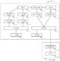
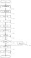
以下、図面を用いて本発明の実施形態を説明する。まず、クライアントサーバ形式での実施形態について説明する。図1に、本発明の操作状況管理システムの全体構成の一例を概念的に示す。実施形態は図1に示すように、操作状況管理サーバA(以下、「管理サーバA」という)が、複数のクライアント端末B(以下、「端末B」という)及び管理者用クライアント端末(以下、「管理者端末C」という)と、通信ネットワークN(以下、「ネットワークN」という)を介して接続されるという形で構成されている。[Client server type]
Hereinafter, embodiments of the present invention will be described with reference to the drawings. First, an embodiment in the client server format will be described. FIG. 1 conceptually shows an example of the overall configuration of the operation status management system of the present invention. In the embodiment, as shown in FIG. 1, the operation status management server A (hereinafter referred to as “management server A”) includes a plurality of client terminals B (hereinafter referred to as “terminal B”) and an administrator client terminal (hereinafter referred to as “terminal B”). It is configured to be connected to a “manager terminal C” via a communication network N (hereinafter referred to as “network N”).
図2に、管理サーバA、端末B又は管理端末Cのハードウェア構成の一例を概念的に示す。FIG. 2 conceptually shows an example of the hardware configuration of the management server A, terminal B, or management terminal C.
管理サーバAは、プログラムの演算処理を実行する演算装置6と、演算結果に基づいて各装置に対する制御指示を出力する制御装置7とを有するCPU等の処理装置1と、情報を記憶するRAMやハードディスク等の記憶装置2と、処理装置1の処理結果や記憶装置2に記憶する情報をインターネットやLAN等のネットワークを介して送受信する通信装置3とを少なくとも有している。管理サーバAが実行する各機能(各手段)は、その処理を実行するプログラムが処理装置1に読み込まれることで実現される。The management server A includes a
管理サーバAは、必要に応じてキーボード、マウス又はテンキー等の入力装置4と、ディスプレイ(画面)等の表示装置5を備えた構成としてもよい。また、管理サーバAは、複数の端末又はサーバにその機能が分散配置されていてもよい。The management server A may include an
端末B及び管理端末Cのハードウェア構成も管理サーバAと同様で、図2に示したとおり、処理装置1、記憶装置2、通信装置3、入力装置4及び表示装置5を有している。The hardware configuration of the terminal B and the management terminal C is the same as that of the management server A, and includes a
ネットワークNは、企業や学校等の限られた施設内において情報を物理的に送信するケーブルと、LANスイッチやハブ等でなる中継機器を備えたCSMA/CD(Carrier Sense Multiple Access With Collision Detection)方式のLANとして構成されたものであるが、このネットワークNとしてLAN以外に、インターネットの技術を用いたイントラネットで構成されたものや、WAN(Wide Area Network)の技術によって構築されるものでもよい。The network N is a CSMA / CD (Carrier Sense Multiple Access Detection Detection) system including a cable that physically transmits information in a limited facility such as a company or a school, and a relay device such as a LAN switch or a hub. However, in addition to the LAN, the network N may be configured by an intranet using Internet technology, or may be constructed by a WAN (Wide Area Network) technology.
〔スタンドアローン形態〕
次に、本発明の別実施形態である、スタンドアローン形式での実施形態について説明する。本実施形態は、中心となる処理を端末Bのみで実行し、管理サーバAは必要としない。端末Bは、図2に示したとおり演算装置1、記憶装置2、通信装置3、入力装置4及び表示装置5を有しており、端末Bが実行する各機能(各手段)は、その処理を実行するプログラムが処理装置1に読み込まれることで実現される。[Stand-alone form]
Next, an embodiment in a stand-alone format, which is another embodiment of the present invention, will be described. In the present embodiment, the central processing is executed only by the terminal B, and the management server A is not required. The terminal B includes the
また、図3に示すように、端末Bと外部表示装置Dとを直接接続又はネットワークNを介して接続し、端末Bで実行された処理結果を外部表示装置Dに表示させるという形で本発明を実施しても構わない。なお、端末Bと接続する外部表示装置Dは、処理結果を表示することのできる機器であればいかなるものでもよい。例えば、端末Bに管理端末Cを接続し、管理端末Cの表示装置5を外部表示装置Dとして使用するという形も考えられる。Further, as shown in FIG. 3, the present invention is configured such that the terminal B and the external display device D are directly connected or connected via the network N, and the processing result executed on the terminal B is displayed on the external display device D. May be carried out. The external display device D connected to the terminal B may be any device that can display the processing result. For example, the management terminal C may be connected to the terminal B, and the
〔実施例1−構成(1)〕
以下、図面を用いて本発明の第一実施例について説明する。まず、実施形態としてクライアントサーバ形態を用いた場合を例に説明する。図4に、本発明の操作状況管理システムを構成する管理サーバA、端末B及び管理端末Cの機能ブロック図を示す。本発明における各構成部及び各手段は、その機能が論理的に区別されているのみであって、物理上あるいは事実上同一の領域を為していてもよい。[Example 1-Configuration (1)]
Hereinafter, a first embodiment of the present invention will be described with reference to the drawings. First, a case where a client server form is used as an embodiment will be described as an example. FIG. 4 shows a functional block diagram of the management server A, terminal B, and management terminal C constituting the operation status management system of the present invention. Each component and each means in the present invention are only logically distinguished in function, and may be physically or virtually identical.
また、図4は、本発明において必要となる最小限度の機器、構成部及び手段等のみを記載しており、その他の機器、構成部及び手段等についてはその記載を省略する。FIG. 4 shows only the minimum equipment, components, and means required in the present invention, and the description of other devices, components, and means is omitted.
管理サーバAは、ネットワークNを介して端末B及び管理端末Cと様々な情報を送受信するためのネットワークI/F10、端末Bにおいて実行された処理の履歴を示す操作ログ情報を取得する操作ログ情報取得部11、取得した操作ログ情報を記憶する操作ログ情報記憶部12、端末Bから出力されたアラーム情報を取得するアラーム情報取得部13、取得したアラーム情報を記憶するアラーム情報記憶部14、記憶されたアラーム情報の発生件数を集計する集計部15、集計された結果情報を記憶する集計結果記憶部16、集計結果の推移を示すグラフを生成する推移グラフ生成部17、集計結果から要注目推移範囲を判定する判定部18、要注目推移範囲を強調する表示情報を生成する強調表示生成部19、推移グラフと強調表示とを表示装置に表示させる表示制御情報を管理端末Cに送信する表示制御部20を備えている。The management server A is a network I /
端末Bは、ネットワークNを介して管理サーバA及び管理端末Cと様々な情報を送受信するためのネットワークI/F30、端末Bに対して各種情報を入力する入力装置4、受信した情報を用いた演算処理の結果に基づいて端末Bの制御処理を実行する端末制御部31、端末制御部31によって指示された情報を表示する表示装置5、端末Bにおいて実行された制御処理の履歴を示す操作ログ情報を生成し管理サーバAに送信する操作ログ情報生成部32、端末Bにおいて実行された問題操作に関するアラーム情報を生成し管理サーバAに送信するアラーム情報生成部33を備えている。The terminal B uses the network I / F 30 for transmitting / receiving various information to / from the management server A and the management terminal C via the network N, the
管理端末Cは、ネットワークNを介して管理サーバA及び端末Bと様々な情報を送受信するためのネットワークI/F40、管理サーバAから管理端末Cに対する制御情報を受信する制御情報受信部41、受信した情報を用いた演算処理の結果に基づいて管理端末Cの制御処理を実行する管理端末制御部42、管理端末制御部42によって指示された情報を表示する表示装置5を備えている。The management terminal C has a network I / F 40 for transmitting / receiving various information to / from the management server A and the terminal B via the network N, a control information receiving unit 41 for receiving control information for the management terminal C from the management server A, and receiving The management
以下、図4に記載した本発明を構成する機能ブロック図に基づいて、各構成部の動作について説明する。はじめに、本発明の操作状況管理システムを構成する、端末Bの構成部について説明する。Hereinafter, based on the functional block diagram which comprises this invention described in FIG. 4, operation | movement of each structure part is demonstrated. First, the component part of the terminal B which comprises the operation condition management system of this invention is demonstrated.
端末制御部31は、入力装置4によって端末Bに入力された各種情報を受信し、受信した情報を用いて演算処理を行い、その結果に基づいて端末Bにおける各種制御処理を実行する。The terminal control unit 31 receives various information input to the terminal B by the
操作ログ情報生成部32は、端末制御部31によって実行された各種制御処理を検出し、操作ログ情報を生成する。そして、生成した操作ログ情報をネットワークI/F30を介して管理サーバAに送信する。The operation log information generation unit 32 detects various control processes executed by the terminal control unit 31 and generates operation log information. Then, the generated operation log information is transmitted to the management server A via the network I / F 30.
上記の操作ログ情報とは、端末Bの入力装置4を用いてユーザにより入力された情報等に基づいて、端末制御部31によって実行された制御処理の内容を示す情報のことをいう。具体的には、制御処理の内容を示す処理内容情報、処理が実行された端末B又は当該端末Bを使用しているユーザを一義的に特定するエージェント情報、及び処理が実行された日時を示す日時情報を含む一連の情報などが一例として考えられる。The operation log information refers to information indicating the content of control processing executed by the terminal control unit 31 based on information input by the user using the
上記のエージェント情報とは、端末Bを一義的に特定するための情報や、端末Bを使用しているユーザを一義的に特定するための情報のことをいう。具体的には、端末BのMACアドレスや端末毎に一義的に設定された番号といった端末個々に設定された番号や符号、及びユーザ毎に一義的に設定されたログインIDやユーザID等がその一例として考えられる。The agent information mentioned above refers to information for uniquely identifying the terminal B and information for uniquely identifying the user who is using the terminal B. Specifically, the number and code set individually for each terminal such as the MAC address of terminal B and the number uniquely set for each terminal, and the login ID and user ID uniquely set for each user are As an example.
さらに、上記の処理内容情報とは、端末において実行された内容を示す情報であって、ミドルウェアまたはOS等において処理されるアプリケーションやハードウェア等による制御を示す情報のことをいう。より具体的には、キー入力、ポインティングデバイスの操作(ボタン押下、移動など)、外部記憶媒体の着脱、外部機器(プリンタなど)との接続、ファイル操作(作成、削除、コピー、移動、フォルダ名変更等)、アプリケーション操作(起動、終了等)、ドライブの追加・削除・検知、IPアドレス変更、記憶媒体の書き込み、印刷、クリップボードへのコピー等を示す情報がある。なお、これらは一例であって限定されるものではない。Furthermore, the processing content information is information indicating the content executed in the terminal, and is information indicating control by an application or hardware processed in middleware or OS. More specifically, key input, pointing device operation (button press, move, etc.), external storage medium attachment / detachment, connection with external device (printer, etc.), file operation (create, delete, copy, move, folder name) Change), application operation (startup, termination, etc.), drive addition / deletion / detection, IP address change, storage medium writing, printing, clipboard copy information, and the like. In addition, these are examples and are not limited.
アラーム情報生成部33は、端末制御部31によって実行される各種制御処理のうち、問題操作に該当する制御処理を検出し、アラーム情報を生成する。そして、生成したアラーム情報をネットワークI/F30を介して管理サーバAに送信する。The alarm
上記のアラーム情報の生成について、アラーム情報生成部33は、操作ログ情報生成部32で生成された操作ログ情報を取得し、問題操作に該当する操作ログ情報を検出してアラーム情報を生成するという形式を用いてもよい。なお、上記の問題操とは、端末制御部31によって実行される単一の制御処理に基づいて検出してもよいし、複数出力される一連の制御処理に基づいて検出するとしてもよい。Regarding the generation of the alarm information, the alarm
次に、本発明の操作状況管理システムを構成する、管理サーバAの構成部について説明する。Next, the configuration part of the management server A constituting the operation status management system of the present invention will be described.
操作ログ情報取得部11は、ネットワークNに接続されている端末Bの操作ログ情報をネットワークI/F10を介して取得し、取得した操作ログ情報を操作ログ情報記憶部12に記憶する。The operation log
操作ログ情報記憶部12には、操作ログ情報取得部11が取得した操作ログ情報が記憶される。その際の記憶形式は、操作ログ情報に含まれるエージェント情報を利用して、端末又はユーザ別に関連付けて記憶するという形式にすると好適である。さらに、操作ログ情報に含まれる日時情報を利用して、操作ログ情報を取得した順に時系列的に記憶するという形式にしてもよい。The operation log
アラーム情報取得部13は、ネットワークNに接続されている端末Bのアラーム情報をネットワークI/F10を介して取得し、取得したアラーム情報をアラーム情報記憶部14に記憶する。The alarm
アラーム情報記憶部14は、アラーム情報取得部13が取得したアラーム情報が記憶される。その際の記憶形式は、アラーム情報に含まれるエージェント情報を利用して、端末又はユーザ別に関連付けて記憶するという形式にすると好適である。さらに、アラーム情報に含まれる日時情報を利用して、アラーム情報を取得した順に時系列的に記憶するという形式にしてもよい。The alarm
集計部15は、操作ログ情報記憶部12に記憶された操作ログ情報の件数と、アラーム情報記憶部14に記憶されたアラーム情報の件数とを所定の集計期間毎に集計し、集計した結果を集計結果記憶部16に記憶する。その際、操作ログ情報の件数に対するアラーム情報の件数の割合を算出し、その算出結果も集計結果として集計結果記憶部16に記憶する。The totaling
集計結果記憶部16は、集計部15が算出した集計結果が記憶される。その際の記憶形式は、操作ログ情報及びアラーム情報の件数を集計する範囲を示す所定の集計期間に含まれる日時情報を利用して、所定期間毎に時系列的に記憶するという形式にすると好適である。さらに、アラーム情報に含まれる問題操作の内容を示す情報に基づいて予めカテゴリを設定し、該当するカテゴリ別に集計結果を分類して記憶するという形式にしてもよい。The aggregation result storage unit 16 stores the aggregation result calculated by the
推移グラフ生成部17は、集計結果記憶部16に記憶されている集計結果に基づいて、推移グラフを生成する。その際、集計を行った集計期間毎に、時系列的なデータの推移が分かるような形式で推移グラフが生成される。The transition graph generation unit 17 generates a transition graph based on the total result stored in the total result storage unit 16. At that time, a transition graph is generated in such a format that the transition of time-series data can be understood for each aggregation period in which the aggregation is performed.
判定部18は、特定の期間における集計結果とその期間の前に隣接する期間の集計結果との差分を算出し、それを推移値として集計結果記憶部16に記憶する。当該推移値は推移範囲ごとに算出されることとする。つぎに、判定部18は、集計結果記憶部16に記憶した推移値と予め定められた所定条件とを比較し、推移値が当該所定条件を満たしている推移範囲を特定し、その推移範囲を要注目推移範囲と判定する。そして、判定した要注目推移範囲に関する情報を強調表示生成部19に送信する。The determination unit 18 calculates a difference between the aggregation result in the specific period and the aggregation result of the adjacent period before that period, and stores it as a transition value in the aggregation result storage unit 16. The transition value is calculated for each transition range. Next, the determination unit 18 compares the transition value stored in the total result storage unit 16 with a predetermined condition, specifies a transition range in which the transition value satisfies the predetermined condition, and determines the transition range. Judged as the range of interest. Then, the information on the determined attention required transition range is transmitted to the highlight
強調表示生成部19は、判定部18から受信した要注目推移範囲に関する情報に基づいて、推移グラフ上で強調表示を行うための強調表示情報を生成し、表示制御部20に送信する。その際、強調表示生成部19は、強調表示のための条件と強調表示の形態を示す表示データとを組み合わせたテーブルを有しており、判定部18から受信した要注目推移範囲に関する情報と強調表示のための条件とを比較し、該当する表示データを特定し、それを基に強調表示情報を生成すると好適である。The highlight
表示制御部20は、推移グラフ生成部17から取得した推移グラフと、強調表示生成部19から取得した強調表示情報とを合成して表示制御情報を生成し、ネットワークI/F10を介して管理端末Cに送信する。The
次に、本発明の操作状況管理システムを構成する、管理端末Cの構成部について説明する。Next, the components of the management terminal C that constitute the operation status management system of the present invention will be described.
制御情報取得部41は、ネットワークNに接続されている管理サーバAの表示制御情報をネットワークI/F40を介して取得し、取得した表示制御情報を管理端末制御部42に送信する。The control information acquisition unit 41 acquires display control information of the management server A connected to the network N via the network I / F 40, and transmits the acquired display control information to the management
管理端末制御部42は、制御情報取得部41から各種制御情報を受信し、受信した情報を用いて演算処理を行い、その結果に基づいて管理端末Cにおける各種制御処理を実行する。ここでは、制御情報取得部41から受信した表示制御情報に基づいて、表示装置5に各種情報を表示する。The management
上述の構成とすることにより、表示装置5において表示される推移グラフにおいて、管理者にとって注目すべき箇所を自動的に強調して表示することが可能となる。With the above-described configuration, it is possible to automatically highlight and display a portion that should be noted by the administrator in the transition graph displayed on the
〔実施例1−構成(2)〕
次に、本発明の第一実施例において、スタンドアローン形態を用いた場合を例に図面を用いて説明する。図5に、本発明の操作状況管理システムを構成する端末B、及び外部表示装置Dの機能ブロック図を示す。本発明における各構成部及び各手段は、その機能が論理的に区別されているのみであって、物理上あるいは事実上同一の領域を為していてもよい。[Example 1-Configuration (2)]
Next, in the first embodiment of the present invention, the case where the stand-alone form is used will be described as an example with reference to the drawings. FIG. 5 shows a functional block diagram of the terminal B and the external display device D constituting the operation status management system of the present invention. Each component and each means in the present invention are only logically distinguished in function, and may be physically or virtually identical.
また、図5は、本発明において必要となる最小限度の機器、構成部及び手段等のみを記載しており、その他の機器、構成部及び手段等についてはその記載を省略する。なお、〔実施例1−構成(1)〕と同一の構成部等には同一の符号を付しており、同じ動作をする場合にはその詳細な説明は省略する。FIG. 5 shows only the minimum equipment, components, means and the like necessary for the present invention, and the description of other devices, components, means, etc. is omitted. In addition, the same code | symbol is attached | subjected to the same component as [Embodiment 1-Configuration (1)], and detailed description thereof is omitted when the same operation is performed.
端末Bは、端末Bの内部に操作ログ情報を記憶する操作ログ情報記憶部12、アラーム情報を記憶するアラーム情報記憶部14、記憶されたアラーム情報の発生件数を集計する集計部15、集計された結果情報を記憶する集計結果記憶部16、集計結果の推移を示すグラフを生成する推移グラフ生成部17、集計結果から要注目推移範囲を判定する判定部18、要注目推移範囲を強調する表示情報を生成する強調表示生成部19、推移グラフと強調表示とを表示させる表示制御情報を表示装置5又は外部表示装置Dに送信する表示制御部20を備えているという点において、〔実施例1−構成(1)〕と異なっている。The terminal B includes an operation log
外部表示装置Dは、端末Bから外部表示装置Dに対する表示制御情報を受信する制御情報取得部50、制御情報取得部50によって取得した制御情報に基づいて表示を行う表示部51を備えている。The external display device D includes a control information acquisition unit 50 that receives display control information for the external display device D from the terminal B, and a display unit 51 that performs display based on the control information acquired by the control information acquisition unit 50.
以下、図5に記載した本発明を構成する機能ブロック図に基づいて、各構成部の動作について説明する。はじめに、本発明の操作状況管理システムを構成する、端末Bの構成部について説明する。なお、〔実施例1−構成(1)〕と同様の構成部又は同様の動作については、その詳細な説明を省略する。Hereinafter, based on the functional block diagram which comprises this invention described in FIG. 5, operation | movement of each structure part is demonstrated. First, the component part of the terminal B which comprises the operation condition management system of this invention is demonstrated. In addition, the detailed description is abbreviate | omitted about the structure part similar to [Example 1-structure (1)] or the same operation | movement.
操作ログ情報生成部32は、端末制御部31によって実行された各種制御処理を検出し、操作ログ情報を生成する。そして、生成した操作ログ情報を操作ログ情報記憶部12に記憶する。The operation log information generation unit 32 detects various control processes executed by the terminal control unit 31 and generates operation log information. Then, the generated operation log information is stored in the operation log
操作ログ情報記憶部12には、操作ログ情報生成部32が生成した操作ログ情報が記憶される。その際の記憶形式は、操作ログ情報に含まれるエージェント情報を利用して、端末又はユーザ別に関連付けて記憶するという形式にすると好適である。さらに、操作ログ情報に含まれる日時情報を利用して、操作ログ情報を取得した順に時系列的に記憶するという形式にしてもよい。The operation log
アラーム情報生成部33は、端末制御部31によって生成される各種制御処理のうち、問題操作に該当する制御処理を検出し、アラーム情報を生成する。そして、生成したアラーム情報をアラーム情報記憶部14に記憶する。The alarm
アラーム情報記憶部14は、アラーム情報生成部33が生成したアラーム情報が記憶される。その際の記憶形式は、アラーム情報に含まれるエージェント情報を利用して、端末又はユーザ別に関連付けて記憶するという形式にすると好適である。さらに、アラーム情報に含まれる日時情報を利用して、アラーム情報を取得した順に時系列的に記憶するという形式にしてもよい。The alarm
表示制御部20は、推移グラフ生成部17から取得した推移グラフと、強調表示生成部19から取得した強調表示情報とを合成して表示制御情報を生成し、表示装置5に表示させる。The
また、表示制御部20は、生成した強調表示情報を、端末Bと接続する外部表示装置Dに対して送信してもよい。Further, the
次に、本発明の操作状況管理システムを構成する、外部表示装置Dの構成部について説明する。Next, the components of the external display device D that constitute the operation status management system of the present invention will be described.
制御情報取得部50は、端末Bから送信された表示制御情報を取得し、取得した表示制御情報を表示部51に送信する。The control information acquisition unit 50 acquires the display control information transmitted from the terminal B, and transmits the acquired display control information to the display unit 51.
表示部51は、制御情報取得部50から取得した表示制御情報に基づいて、外部表示装置Dの表示装置(図示せず)に表示する。The display unit 51 displays on a display device (not shown) of the external display device D based on the display control information acquired from the control information acquisition unit 50.
上述の構成とすることにより、管理サーバAを設けることなく、端末B単体で本発明の実現が可能となる。With the above-described configuration, the present invention can be realized by the terminal B alone without providing the management server A.
〔実施例1−処理プロセス(1)〕
次に、本発明の操作状況監視システムをクライアントサーバ形態で動作させる場合における処理プロセスの一例を、図4の機能ブロック図及び図6のフローチャート等を用いて説明する。[Example 1-Treatment process (1)]
Next, an example of a processing process when the operation status monitoring system of the present invention is operated in the form of a client server will be described with reference to the functional block diagram of FIG. 4 and the flowchart of FIG.
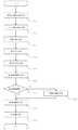
管理サーバAの操作ログ情報取得部11は、端末Bの操作ログ情報生成部32によって生成された操作ログ情報を取得し、操作ログ情報記憶部12に記憶する(S101)。なお、操作ログ情報生成部32による操作ログ情報の送信タイミングは、操作ログ情報を生成した時点で、その都度送信するという形式としても良いし、生成した操作ログ情報を所定期間溜め込み、特定のタイミングで一度に送信するという形式でも良い。The operation log
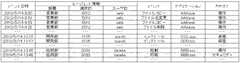
図7に、操作ログ情報記憶部12に記憶される操作ログ情報の一例を示す。この図に示すとおり、以下の処理プロセスでは具体的に、操作ログ情報に含まれる処理内容情報として「イベント」、予め設定される処理内容の分類を示す「カテゴリ」、どの問題操作の類型に該当するかを示すアラーム類型情報として「アラーム類型」、エージェント情報として「部署ID」・「端末ID」・「ユーザID」、日時情報として「イベント日時」という項目が用いられる、という場合を例に説明する。FIG. 7 shows an example of operation log information stored in the operation log
上記のアラーム類型について、ここでは、端末のハードウェア構成やソフトウェア構成に変更を加える操作を「資産変更」、管理者が予め定めたアプリケーション以外の不許可アプリケーションを起動する操作を「アプリ」、管理者が予め定めた違反操作内容に該当する操作を「違反操作」、管理者が予め閲覧禁止と設定したWebページを閲覧する操作を「Web」、予め印刷禁止と設定した文書を印刷したり、予め定められたプリント枚数以上の枚数を印刷したりする操作を「印刷」として表示することとする。For the above alarm types, here, the operation to change the hardware and software configuration of the terminal is “change asset”, the operation to start unauthorized applications other than the application predetermined by the administrator is “app”, and management An operation corresponding to the content of the violating operation determined in advance by the user is “violating operation”, an operation of browsing the Web page set by the administrator in advance is set to “Web”, a document set to be prohibited from printing is printed, It is assumed that an operation for printing more than a predetermined number of prints is displayed as “print”.
管理サーバAのアラーム情報取得部13は、端末Bのアラーム情報生成部33によって生成されたアラーム情報を取得し、アラーム情報記憶部14に記憶する(S102)。なお、アラーム情報生成部33によるアラーム情報の送信タイミングは、アラーム情報を生成した時点で、その都度送信するという形式としても良いし、生成したアラーム情報を所定期間溜め込み、特定のタイミングで一度に送信するという形式でも良い。The alarm
図8に、アラーム情報記憶部14に記憶されるアラーム情報の一例を示す。この図に示すとおり、以下の処理プロセスでは具体的に、アラーム情報に含まれる問題操作の内容を示す情報として「イベント」、予め設定される処理内容の分類を示す「カテゴリ」、エージェント情報として「部署ID」・「端末ID」・「ユーザID」、日時情報として「イベント日時」という項目が用いられるという場合を例に説明する。FIG. 8 shows an example of alarm information stored in the alarm
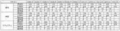
集計部15は、所定期間毎の操作ログ情報及びアラーム情報の出力件数を集計し、結果を集計結果記憶部16に記憶する(S103)。なお、その所定期間毎の操作ログ情報件数の中に含まれるアラーム情報件数の割合を集計結果として算出するとしても良い。また、集計結果をイベントのカテゴリ別に算出して記憶するという形式としても良い。The totaling
図9に、集計結果記憶部16に記憶される集計結果の一例を示す。この図では、所定期間を1ヶ月とし、1ヶ月毎に集計した結果を、処理内容のカテゴリ別に示している。さらに、操作ログ情報件数の中に含まれるアラーム情報件数の割合を「異常率」、そして操作ログ情報件数の中でアラーム情報件数を除いた割合を「正常率」として表示している。以下の処理プロセスでは、この「正常率」を用いる場合を例に説明する。FIG. 9 shows an example of the total results stored in the total result storage unit 16. In this figure, the predetermined period is set to one month, and the results totaled for each month are shown for each processing category. Furthermore, the ratio of the number of alarm information included in the number of operation log information is displayed as “abnormal rate”, and the ratio of the number of operation log information excluding the number of alarm information is displayed as “normal rate”. In the following processing process, a case where this “normal rate” is used will be described as an example.
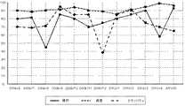
推移グラフ生成部17は、集計結果記憶部16に記憶されている「2009年6月」から「2010年5月」までの「正常率」のデータを用いて、推移グラフを生成する(S104)。図10に、生成された推移グラフの一例を示す。The transition graph generation unit 17 generates a transition graph using the “normal rate” data from “June 2009” to “May 2010” stored in the tabulation result storage unit 16 (S104). . FIG. 10 shows an example of the generated transition graph.
判定部18は、推移範囲における「正常率」の差分を「推移値」として算出し、集計結果記憶部16に記憶する(S105)。図11に、推移値が記憶された状態の集計結果記憶部16の一例を示す。つぎに、判定部18は、集計結果記憶部16に記憶されている推移値に基づき、要注目推移範囲を判定する(S105)。なお、本処理プロセスでは、予め所定値を推移値「−25」と定め、推移値が「−25未満」の推移範囲を、要注目推移範囲と判定することとする。その結果、カテゴリ「操作」の「2009年8月から2009年8月」・「2010年3月から2010年4月」、カテゴリ「セキュリティ」の「2009年11月から2009年12月」が要注目推移範囲と判定される(S107)。The determination unit 18 calculates the difference of the “normal rate” in the transition range as the “transition value” and stores it in the total result storage unit 16 (S105). FIG. 11 shows an example of the tabulation result storage unit 16 in a state where transition values are stored. Next, the determination unit 18 determines a transition range requiring attention based on the transition value stored in the total result storage unit 16 (S105). In this processing process, a predetermined value is set in advance as a transition value “−25”, and a transition range having a transition value “less than −25” is determined as a transition range requiring attention. As a result, the category “Operation” requires “August 2009 to August 2009” and “March 2010 to April 2010” and the category “Security” requires “November 2009 to December 2009”. It is determined as the attention transition range (S107).
強調表示生成部19は、要注目推移範囲のデータ推移状況を強調するための強調表示情報を生成する(S108)。なお、本処理プロセスでは強調表示情報として、推移グラフ上におけるデータとデータの推移を示す線の形状を変化させるという形の強調表示情報を生成することとする。その他、推移グラフ上において、要注目推移範囲のデータ推移を示す線のそばにコメント等が記載された吹き出しを表示するという形の強調表示情報、データ推移を示す線の色を変化させるという強調表示情報、又は要注目である旨を示すマークや図形を表示するという形の強調表示情報を生成するという形式としても良い。The emphasis
また、強調表示生成部19が生成する強調表示情報の一例として、要注目推移範囲のデータ推移を示す線のそばに、当該要注目推移範囲において取得されたアラーム情報のうち、取得件数が一番多かった(または一番少なかった)アラーム類型を表示するという形式としてもよい。この形式にすることにより、要注目推移範囲において、どの類型に属する問題操作が多く行われていたのかという情報を容易に確認することが可能となる。Moreover, as an example of the highlight display information generated by the highlight
表示制御部20は、推移グラフと強調表示情報とを合成し、表示制御情報を生成する(S109)。生成された表示制御情報は管理端末Cに送信され、管理端末制御部42によって、管理端末Cの表示装置5に表示される(S110)。The
図12に、表示装置5に表示される画像のイメージを示す。この図では、管理端末Cの表示装置5の画面60と、管理サーバAから受信した表示制御情報を表示するための表示ウィンドウ61と、アラーム情報発生件数の時系列的な推移を示す推移グラフを表示させるための表示領域62と、折れ線グラフ形式の推移グラフ63と、要注目推移範囲のデータ推移を強調する強調表示情報64の具体例を示している。FIG. 12 shows an image displayed on the
〔実施例1−処理プロセス(2)〕
次に、本発明の操作状況監視システムをクライアントサーバ形態で動作させる場合における処理プロセスの別の一例について、図4の機能ブロック図及び図6のフローチャート等を用いて説明する。なお、図6のフローチャートにおける(S101)から(S105)の動作については、〔実施例1−処理プロセス(1)〕と同様のため、その詳細を省略する。[Example 1-Treatment process (2)]
Next, another example of the processing process when the operation status monitoring system of the present invention is operated in the form of a client server will be described with reference to the functional block diagram of FIG. 4, the flowchart of FIG. Since the operations from (S101) to (S105) in the flowchart of FIG. 6 are the same as those in [Example 1-Processing process (1)], the details thereof are omitted.
判定部18は、集計結果記憶部16に記憶されている「推移値」に基づき、要注目推移範囲を判定する(S106)。なお、本処理プロセスでは、予め、推移値「−25未満」の推移範囲を「レベル1」、推移値「−35未満」の推移範囲を「レベル2」、推移値「−45未満」の推移範囲を「レベル3」と定め、それぞれに該当する期間を要注目推移範囲と判定し、重要度別に分類することとする。その結果、「レベル1」はカテゴリ「操作」の「2010年3月から2010年4月」、「レベル2」はカテゴリ「操作」の「2009年8月から2009年8月」、「レベル3」は「セキュリティ」の「2009年11月から2009年12月」と判定される(S107)。The determination unit 18 determines the transition range requiring attention based on the “transition value” stored in the aggregation result storage unit 16 (S106). In this processing process, the transition range of the transition value “less than −25” is “
強調表示生成部19は、要注目推移範囲のデータを強調するための強調表示情報を生成する(S108)。なお、本処理プロセスでは強調表示情報として、推移グラフ上におけるデータ推移を示す線の形状を、重要度別に変化させるという形の強調表示情報を生成することとする。具体的には、「レベル1」、「レベル2」、「レベル3」と重要度が上がるにつれ、より目立つような強調表示情報が生成されることとする。The highlight
上記の「より目立つような強調表示情報」とは、推移グラフ上における要注目推移範囲のデータ推移を示す線について、他のデータ推移を示す線と差別化するために、視覚的に異なる表示をすることをいう。具体的には、線の形状を変化させる(から二重線や三重線に変化させる。または、波線型に変化させるなど)、線のサイズを太くする(他の線と比べて2倍や3倍の太さにする)、線の色を変化させる(他の線とは違う色にする。または線の色を点滅させるなど)というような表示が考えられる。なお、これらは一例であって限定されるものではない。The above-mentioned “highlighting highlight information” means that the line indicating the data transition in the transitional area of interest on the transition graph has a visually different display to differentiate it from the line indicating other data transitions. To do. Specifically, the line shape is changed (from double line or triple line, or changed to a wavy line, etc.), and the line size is increased (twice or 3 times that of other lines). It is possible to display such as changing the color of the line (changing the color of the line to a different color from other lines or blinking the color of the line). In addition, these are examples and are not limited.
表示制御部20は、推移グラフと強調表示情報とを合成し、表示制御情報を生成する(S109)。生成された表示制御情報は管理端末Cに送信され、管理端末制御部42によって、管理端末Cの表示装置5に表示される(S110)。図13に、表示装置5に表示される画像のイメージを示す。なお、ここでは、重要度のレベル別に強調表示の形式を変化させるという形式としているが、その他、要注目推移範囲のデータ推移を示す線のそばに重要度レベルを示す数字等を表示するという形式としても良い。The
〔実施例1−処理プロセス(3)〕
次に、本発明の操作状況監視システムをクライアントサーバ形態で動作させる場合における処理プロセスの別の一例について、図4の機能ブロック図及び図6のフローチャート等を用いて説明する。なお、図6のフローチャートにおける(S101)から(S105)の動作については、〔実施例1−処理プロセス(1)〕と同様のため、その詳細を省略する。[Example 1-Treatment process (3)]
Next, another example of the processing process when the operation status monitoring system of the present invention is operated in the form of a client server will be described with reference to the functional block diagram of FIG. 4, the flowchart of FIG. Since the operations from (S101) to (S105) in the flowchart of FIG. 6 are the same as those in [Example 1-Processing process (1)], the details thereof are omitted.
判定部18は、集計結果記憶部16に記憶されている「推移値」に基づき、要注目推移範囲を判定する(S106)。なお、本処理プロセスでは、推移グラフを生成する集計期間の範囲内において、推移値が一番高い値と一番低い値の両方を抽出し、それぞれを要注目推移範囲と判定することとする。その結果、カテゴリ「セキュリティ」の「2009年11月から2009年12月」・「2009年12月から2010年1月」と判定される(S107)。The determination unit 18 determines the transition range requiring attention based on the “transition value” stored in the aggregation result storage unit 16 (S106). In this processing process, both the highest value and the lowest value of the transition value are extracted within the range of the aggregation period for generating the transition graph, and each of them is determined to be the attention transition range. As a result, the categories “security” are determined as “November 2009 to December 2009” and “December 2009 to January 2010” (S107).
強調表示生成部19は、要注目推移範囲のデータを強調するための強調表示情報を生成する(S108)。なお、本処理プロセスでは強調表示情報として、推移グラフ上におけるデータ推移を示す線の形状を変化させるという形の強調表示情報を生成することとする。The highlight
表示制御部20は、推移グラフと強調表示情報とを合成し、表示制御情報を生成する(S109)。生成された表示制御情報は管理端末Cに送信され、管理端末制御部42によって、管理端末Cの表示装置5に表示される(S110)。図14に、表示装置5に表示される画像のイメージを示す。ここで示す強調表示の形式以外にも、例えば、要注目推移範囲のデータを示す点のそばに最大値又は最小値を示す表示を行うという形式としても良い。The
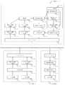
〔実施例2−構成(1)〕
以下、図面を用いて本発明の第二実施例について説明する。まず、実施形態としてクライアントサーバ形態を用いた場合を例に説明する。図15に、本発明の操作状況管理システムを構成する管理サーバA、端末B及び管理端末Cの機能ブロック図を示す。本発明における各構成部及び各手段は、その機能が論理的に区別されているのみであって、物理上あるいは事実上同一の領域を為していてもよい。[Example 2-Configuration (1)]
The second embodiment of the present invention will be described below with reference to the drawings. First, a case where a client server form is used as an embodiment will be described as an example. FIG. 15 shows a functional block diagram of the management server A, terminal B, and management terminal C constituting the operation status management system of the present invention. Each component and each means in the present invention are only logically distinguished in function, and may be physically or virtually identical.
また、図15は、本発明において必要となる最小限度の機器、構成部及び手段等のみを記載しており、その他の機器、構成部及び手段等についてはその記載を省略する。なお、〔実施例1−構成(1)〕と同一の構成部等には同一の符号を付しており、同じ動作をする場合にはその詳細な説明は省略する。FIG. 15 shows only the minimum equipment, components, means and the like necessary in the present invention, and the description of the other devices, components, means, etc. is omitted. In addition, the same code | symbol is attached | subjected to the same component as [Embodiment 1-Configuration (1)], and detailed description thereof is omitted when the same operation is performed.
管理サーバAは、判定部18の内部に、集計結果記憶部16に記憶されている情報から推移範囲の推移値を算出する推移値算出手段21と、集計結果記憶部16に記憶されている情報から、推移範囲と同時期における前年度の推移値を基準値として算出する基準値算出手段22と、算出した推移値と基準値とを比較して要注目推移範囲を判定する要注目推移範囲判定手段23とを備えているという点において、〔実施例1−構成(1)〕と異なっている。The management server A includes a transition value calculation means 21 for calculating a transition value of the transition range from information stored in the total result storage unit 16 and information stored in the total result storage unit 16 inside the determination unit 18. From the reference range calculation means 22 for calculating the transition value of the previous year in the same period as the transition range, and the transition range determination requiring attention by comparing the calculated transition value and the reference value to determine the transition range of interest It differs from [Example 1-Configuration (1)] in that it has means 23.
以下、図15に記載した本発明を構成する機能ブロック図に基づいて、各構成部の動作について説明する。なお、〔実施例1−構成(1)〕と同様の構成部又は同様の動作については、その詳細な説明を省略する。The operation of each component will be described below based on the functional block diagram constituting the present invention shown in FIG. In addition, the detailed description is abbreviate | omitted about the structure part similar to [Example 1-structure (1)] or the same operation | movement.
推移値算出手段21は、集計結果記憶部16に記憶されている情報から、各集計期間毎に、その集計期間の前に隣接する集計期間の値を取得し、それぞれの差分を算出する。その算出した差分を推移値としてを要注目推移範囲判定手段23に送信する。The transition value calculation means 21 acquires the value of the adjacent total period before the total period for each total period from the information stored in the total result storage unit 16 and calculates each difference. The calculated difference is transmitted as a transition value to the transition range determining means 23 requiring attention.
推移値算出手段22は、推移値算出手段21によって推移値を算出した集計期間と同時期の前年度の集計期間に関する集計値を、集計結果記憶部16に記憶されている情報から抽出する。さらに、抽出した集計値に基づいて、それぞれの推移範囲関する前年度の推移値を算出する。その算出した推移値を基準値としてを要注目推移範囲判定手段23に送信する。The transition value calculation unit 22 extracts a total value related to the total period of the previous year that is the same as the total period calculated by the transition
要注目推移範囲判定手段23は、取得した推移値と基準値とを比較し、予め定めた判定条件に該当する推移範囲を特定し、その推移範囲を要注目推移範囲と判定する。そして、判定した要注目推移範囲に関する情報を強調表示生成部19に送信する。The attention required transition range determination means 23 compares the acquired transition value with a reference value, specifies a transition range that meets a predetermined determination condition, and determines the transition range as a attention required transition range. Then, the information on the determined attention required transition range is transmitted to the highlight
上述の構成とすることにより、表示装置5において表示される推移グラフにおいて、例年とは異なる異常な値の変化を示している範囲を自動的に強調表示することができるため、管理者は注目すべき箇所を容易に特定することが可能となる。With the above-described configuration, the transition graph displayed on the
〔実施例2−構成(2)〕
次に、本発明の第二実施例において、スタンドアローン形態を用いた場合を例に図面を用いて説明する。図16に、本発明の操作状況管理システムを構成する端末B、及び外部表示装置Dの機能ブロック図を示す。本発明における各構成部及び各手段は、その機能が論理的に区別されているのみであって、物理上あるいは事実上同一の領域を為していてもよい。[Example 2-Configuration (2)]
Next, in the second embodiment of the present invention, the case where the stand-alone form is used will be described as an example with reference to the drawings. In FIG. 16, the functional block diagram of the terminal B and the external display apparatus D which comprise the operation condition management system of this invention is shown. Each component and each means in the present invention are only logically distinguished in function, and may be physically or virtually identical.
また、図16は、本発明において必要となる最小限度の機器、構成部及び手段等のみを記載しており、その他の機器、構成部及び手段等についてはその記載を省略する。なお、〔実施例1−構成(2)〕と同一の構成部等には同一の符号を付しており、同じ動作をする場合にはその詳細な説明は省略する。FIG. 16 shows only the minimum equipment, components, means and the like necessary in the present invention, and the description of other devices, components, means, etc. is omitted. In addition, the same code | symbol is attached | subjected to the same structure part etc. as [Example 1-structure (2)], and the detailed description is abbreviate | omitted when performing the same operation | movement.
端末Bは、判定部18の内部に、集計結果記憶部16に記憶されている情報から推移範囲の推移値を算出する推移値算出手段21と、集計結果記憶部16に記憶されている情報から、推移範囲と同時期における前年度の推移値を基準値として算出する基準値算出手段22と、算出した推移値と基準値とを比較して要注目推移範囲を判定する要注目推移範囲判定手段23とを備えているという点において、〔実施例1−構成(2)〕と異なっている。The terminal B includes a transition value calculation means 21 that calculates a transition value of the transition range from information stored in the total result storage unit 16 and information stored in the total result storage unit 16 inside the determination unit 18. The reference value calculation means 22 for calculating the transition value of the previous year in the same period as the transition range as the reference value, and the required transition range determination means for comparing the calculated transition value and the reference value to determine the attention transition range And [Example 1-Configuration (2)].
上述の構成とすることにより、管理サーバAを設けることなく、端末B単体で本発明の実現が可能となる。With the above-described configuration, the present invention can be realized by the terminal B alone without providing the management server A.
〔実施例2−処理プロセス〕
次に、本発明の操作状況監視システムをクライアントサーバ形態で動作させる場合における処理プロセスの一例について、図15の機能ブロック図及び図17のフローチャート等を用いて説明する。なお、図17のフローチャートにおける(S201)から(S204)の動作については、〔実施例1−処理プロセス(1)〕と同様のため、その詳細を省略する。Example 2 Treatment Process
Next, an example of a processing process when the operation status monitoring system of the present invention is operated in the form of a client server will be described with reference to the functional block diagram of FIG. 15, the flowchart of FIG. Note that the operations from (S201) to (S204) in the flowchart of FIG. 17 are the same as those in [Example 1-Processing process (1)], and thus the details thereof are omitted.
判定部18の推移値算出手段21は、推移範囲における「正常率」の差分を「推移値」として算出し、集計結果記憶部16に記憶する(S205)。図11に、推移値が記憶された状態の集計結果記憶部16の一例を示す。The transition value calculation means 21 of the determination unit 18 calculates the difference of “normal rate” in the transition range as a “transition value” and stores it in the total result storage unit 16 (S205). FIG. 11 shows an example of the tabulation result storage unit 16 in a state where transition values are stored.
判定部18の基準値算出手段22は、前年度における同時期の「正常率」を集計結果記憶部16から抽出し、推移範囲ごとに「正常率」の差分を「基準値」として算出し、集計結果記憶部16に記憶する(S206)。図18に、基準値が記憶された状態の集計結果記憶部16の一例を示す。The reference value calculation means 22 of the determination unit 18 extracts the “normal rate” of the same period in the previous year from the total result storage unit 16 and calculates the difference of the “normal rate” for each transition range as the “reference value”. The result is stored in the total result storage unit 16 (S206). FIG. 18 shows an example of the tabulation result storage unit 16 in a state where the reference value is stored.
判定部18の要注目推移範囲判定手段23は、集計期間記憶部16に記憶されている「推移値」と「基準値」を比較し、要注目推移範囲を判定する(S207)。なお、本処理プロセスでは、予め所定値を、推移値と基準値との差「20以上」と定め、該当する推移範囲を要注目推移範囲と判定することとする。その結果、カテゴリ「操作」の「2009年8月から2009年9月」・「2010年3月から2010年4月」、カテゴリ「セキュリティ」の「2009年11月から2009年12月」が要注目推移範囲と判定される。The attention required transition range determination means 23 of the determination unit 18 compares the “transition value” stored in the tabulation period storage unit 16 with the “reference value”, and determines the attention required transition range (S207). In this processing process, the predetermined value is set in advance as a difference “20 or more” between the transition value and the reference value, and the corresponding transition range is determined as the transition range requiring attention. As a result, the category “Operation” requires “August 2009 to September 2009” and “March 2010 to April 2010” and the category “Security” requires “November 2009 to December 2009”. It is determined as the attention transition range.
強調表示生成部19は、要注目推移範囲のデータを強調するための強調表示情報を生成する(S209)。なお、本処理プロセスでは強調表示情報として、推移グラフ上におけるデータ推移を示す線の形状を変化させるという形の強調表示情報を生成することとする。The highlight
表示制御部20は、推移グラフと強調表示情報とを合成し、表示制御情報を生成する(S210)。生成された表示制御情報は管理端末Cに送信され、管理端末制御部42によって、管理端末Cの表示装置5に表示される(S211)。図19に、表示装置5に表示される画像のイメージを示す。The
〔実施例3−構成(1)〕
以下、図面を用いて本発明の第三実施例について説明する。まず、実施形態としてクライアントサーバ形態を用いた場合を例に説明する。図20に、本発明の操作状況管理システムを構成する管理サーバA、端末B及び管理端末Cの機能ブロック図を示す。本発明における各構成部及び各手段は、その機能が論理的に区別されているのみであって、物理上あるいは事実上同一の領域を為していてもよい。[Example 3-Configuration (1)]
Hereinafter, a third embodiment of the present invention will be described with reference to the drawings. First, a case where a client server form is used as an embodiment will be described as an example. FIG. 20 shows a functional block diagram of the management server A, terminal B, and management terminal C constituting the operation status management system of the present invention. Each component and each means in the present invention are only logically distinguished in function, and may be physically or virtually identical.
また、図20は、本発明において必要となる最小限度の機器、構成部及び手段等のみを記載しており、その他の機器、構成部及び手段等についてはその記載を省略する。なお、〔実施例1−構成(1)〕及び〔実施例2−構成(1)〕と同一の構成部等には同一の符号を付しており、同じ動作をする場合にはその詳細な説明は省略する。FIG. 20 shows only the minimum equipment, components, means, and the like necessary for the present invention, and the descriptions of other devices, components, means, etc. are omitted. In addition, the same code | symbol is attached | subjected to the component etc. which are the same as [Example 1-configuration (1)] and [Example 2-configuration (1)], and when performing the same operation, its detailed Description is omitted.
管理サーバAは、判定部18の内部に、集計結果記憶部16に記憶されている情報から特定の推移範囲における推移値を算出する推移値算出手段21と、その推移値の連続的な変化状況を判定する連続変化状況判定手段24と、連続変化状況が所定条件に合致するかを判定する要注目推移範囲判定手段23とを備えているという点において、〔実施例1−構成(1)〕及び〔実施例2−構成(1)〕と異なっている。The management server A includes a transition value calculation means 21 that calculates a transition value in a specific transition range from information stored in the totalization result storage unit 16 inside the determination unit 18, and a continuous change state of the transition value. [Embodiment 1-Configuration (1)] in that it includes a continuous change status determination means 24 for determining whether or not a continuous change status matches a predetermined condition. And [Example 2-Configuration (1)].
以下、図20に記載した本発明を構成する機能ブロック図に基づいて、各構成部の動作について説明する。なお、〔実施例1−構成(1)〕及び〔実施例2−構成(1)〕と同様の構成部又は同様の動作については、その詳細な説明を省略する。The operation of each component will be described below based on the functional block diagram constituting the present invention shown in FIG. In addition, the detailed description is abbreviate | omitted about the structure part similar to [Example 1-configuration (1)] and [Example 2-configuration (1)] or the same operation.
推移値算出手段21は、集計結果記憶部16に記憶されている情報から、集計範囲毎に推移値を算出する。そして、算出した推移値を集計結果記憶部16に記憶する。The transition value calculation means 21 calculates a transition value for each aggregation range from the information stored in the aggregation result storage unit 16. Then, the calculated transition value is stored in the total result storage unit 16.
連続変化状況判定手段24は、集計結果記憶部16に記憶されている情報から、推移範囲毎に、その推移範囲の前に隣接する推移範囲の値を取得し、それぞれの差分について判定する。そしてその判定結果を連続変化状況という情報にまとめて集計結果記憶部16に記憶する。The continuous change status determination unit 24 acquires, for each transition range, the value of the transition range adjacent to the transition range from the information stored in the tabulation result storage unit 16, and determines each difference. Then, the determination results are collected into information called continuous change status and stored in the total result storage unit 16.
要注目推移範囲判定手段23は、集計結果記憶部16に記憶されている連続変化状況の情報を取得し、その連続変化状況が予め定められた判定条件を満たしている推移範囲を特定し、その推移範囲を要注目推移範囲と判定する。そして、判定した要注目推移範囲に関する情報を強調表示生成部19に送信する。The attention transition range determination means 23 acquires information on the continuous change status stored in the tabulation result storage unit 16, identifies the transition range in which the continuous change status satisfies a predetermined determination condition, The transition range is determined as the attention transition range requiring attention. Then, the information on the determined attention required transition range is transmitted to the highlight
上述の構成とすることにより、表示装置5において表示される推移グラフにおいて、データが一定方向に連続的に変化している範囲を自動的に強調表示することができるため、管理者は注目すべき箇所を容易に特定することが可能となる。With the above-described configuration, the range in which data continuously changes in a certain direction can be automatically highlighted in the transition graph displayed on the
〔実施例3−構成(2)〕
次に、本発明の第三実施例において、スタンドアローン形態を用いた場合を例に図面を用いて説明する。図21に、本発明の操作状況管理システムを構成する端末B、及び外部表示装置Dの機能ブロック図を示す。本発明における各構成部及び各手段は、その機能が論理的に区別されているのみであって、物理上あるいは事実上同一の領域を為していてもよい。[Example 3-Configuration (2)]
Next, in the third embodiment of the present invention, the case where the stand-alone form is used will be described as an example with reference to the drawings. FIG. 21 shows a functional block diagram of the terminal B and the external display device D constituting the operation status management system of the present invention. Each component and each means in the present invention are only logically distinguished in function, and may be physically or virtually identical.
また、図21は、本発明において必要となる最小限度の機器、構成部及び手段等のみを記載しており、その他の機器、構成部及び手段等についてはその記載を省略する。なお、〔実施例1−構成(2)〕及び〔実施例2−構成(2)〕と同一の構成部等には同一の符号を付しており、同じ動作をする場合にはその詳細な説明は省略する。FIG. 21 shows only the minimum equipment, components, means and the like necessary in the present invention, and the description of the other devices, components, means, etc. is omitted. In addition, the same code | symbol is attached | subjected to the same structural part etc. as [Example 1-configuration (2)] and [Example 2-configuration (2)], and the same operation will be described in detail. Description is omitted.
端末Bは、は、判定部18の内部に、集計結果記憶部16に記憶されている情報から特定の推移範囲における推移値を算出する推移値算出手段21と、その推移値の連続的な変化状況を判定する連続変化状況判定手段24と、連続変化状況が所定条件に合致するかを判定する要注目推移範囲判定手段23とを備えているという点において、〔実施例1−構成(2)〕及び〔実施例2−構成(2)〕と異なっている。The terminal B has a transition value calculation means 21 for calculating a transition value in a specific transition range from information stored in the total result storage unit 16 inside the determination unit 18 and a continuous change in the transition value. [Embodiment 1-Configuration (2)] In that a continuous change situation determination means 24 for judging a situation and a change-of-interest range determination means 23 for judging whether a continuous change situation meets a predetermined condition are provided. ] And [Example 2-Configuration (2)].
上述の構成とすることにより、管理サーバAを設けることなく、端末B単体で本発明の実現が可能となる。With the above-described configuration, the present invention can be realized by the terminal B alone without providing the management server A.
〔実施例3−処理プロセス〕
次に、本発明の操作状況監視システムをクライアントサーバ形態で動作させる場合における処理プロセスの一例について、図20の機能ブロック図及び図22のフローチャート等を用いて説明する。なお、図22のフローチャートにおける(S301)から(S305)の動作については、〔実施例1−処理プロセス(1)〕と同様のため、その詳細を省略する。Example 3 Treatment Process
Next, an example of a processing process when the operation status monitoring system of the present invention is operated in the form of a client server will be described with reference to the functional block diagram of FIG. 20, the flowchart of FIG. Note that the operations from (S301) to (S305) in the flowchart of FIG. 22 are the same as those in [Example 1-Processing process (1)], and thus the details thereof are omitted.
判定部18の連続変化状況判定手段24は、集計結果記憶部16から、推移範囲毎に、当該推移範囲の「推移値」と、その前に隣接する推移範囲の「推移値」を比較し、その差分を連続変化状況という情報にまとめて集計結果記憶部16に記憶する(S306)。図23に、連続変化状況が記憶された集計結果記憶部16の一例を示す。なお、本処理プロセスでは、対象となっている推移範囲の「推移値」が隣接する前推移範囲の「推移値」よりも増加している場合は「+」、減少している場合は「−」の記号が記憶されることとする。The continuous change status determination means 24 of the determination unit 18 compares the “transition value” of the transition range with the “transition value” of the adjacent transition range from the total result storage unit 16 for each transition range, The differences are grouped into information of continuous change status and stored in the total result storage unit 16 (S306). FIG. 23 shows an example of the tabulation result storage unit 16 in which the continuous change status is stored. In this process, the “transition value” of the target transition range is “+” if it is greater than the “transition value” of the adjacent previous transition range, and “−” if it is decreasing. "Is stored.
判定部18の要注目推移範囲判定手段23は、予め設定された判定条件に基づき、要注目推移範囲を判定する(S307)。なお、本処理プロセスでは、判定条件として、対象推移範囲の記号と前推移範囲の記号が同一で、かつ「−」である場合、その対象推移範囲を、要注目推移範囲と判定することとする。その結果、カテゴリ「操作」の「2009年10月から2009年11月」・「2010年2月から2010年3月」・「2010年3月から2010年4月」、カテゴリ「資産」の「2009年11月から2009年12月」・「2009年12月から2010年1月」、カテゴリ「セキュリティ」の「2010年3月から2010年4月」・「2010年4月から2010年5月」が要注目推移範囲と判定される(S308)。The attention required transition range determination means 23 of the determination unit 18 determines the attention required transition range based on a preset determination condition (S307). In this processing process, if the symbol of the target transition range and the symbol of the previous transition range are the same as the determination condition and “−”, the target transition range is determined to be a transition range requiring attention. . As a result, “October 2009 to November 2009”, “February 2010 to March 2010”, “March 2010 to April 2010” in the category “Operation”, “ "November 2009 to December 2009", "December 2009 to January 2010", category "Security" from "March 2010 to April 2010", "April 2010 to May 2010 "Is determined as the attention-needing transition range (S308).
強調表示生成部19は、要注目推移範囲のデータを強調するための強調表示情報を生成する(S309)。なお、本処理プロセスでは強調表示情報として、推移グラフ上におけるデータ推移を示す線の形状を変化させるという形の強調表示情報を生成することとする。The highlight
表示制御部20は、推移グラフと強調表示情報とを合成し、表示制御情報を生成する(S310)。生成された表示制御情報は管理端末Cに送信され、管理端末制御部42によって、管理端末Cの表示装置5に表示される(S311)。図24に、表示装置5に表示される画像のイメージを示す。The
A:管理サーバ
B:端末
C:管理端末
D:外部表示装置
1:処理装置
2:記憶装置
3:通信装置
4:入力装置
5:表示装置
6:演算装置
7:制御装置
10:ネットワークI/F
11:操作ログ情報取得部
12:操作ログ情報記憶部
13:アラーム情報取得部
14:アラーム情報記憶部
15:集計部
16:集計結果記憶部
17:推移グラフ生成部
18:判定部
19:強調表示生成部
20:表示制御部
21:推移値算出手段
22:基準値算出手段
23:要注目推移範囲判定手段
24:連続変化状況判定手段
30:ネットワークI/F
31:端末制御部
32:操作ログ情報生成部
33:アラーム情報生成部
40:ネットワークI/F
41:制御情報取得部
42:管理端末制御部
50:制御情報取得部
51:表示部
60:画面
61:表示ウィンドウ
62:表示領域
63:推移グラフ
64:強調表示情報
A: Management server B: Terminal C: Management terminal D: External display device 1: Processing device 2: Storage device 3: Communication device 4: Input device 5: Display device 6: Arithmetic device 7: Control device 10: Network I / F
11: Operation log information acquisition unit 12: Operation log information storage unit 13: Alarm information acquisition unit 14: Alarm information storage unit 15: Total unit 16: Total result storage unit 17: Transition graph generation unit 18: Determination unit 19: Highlight display Generation unit 20: Display control unit 21: Transition value calculation means 22: Reference value calculation means 23: Interesting transition range determination means 24: Continuous change status determination means 30: Network I / F
31: Terminal control unit 32: Operation log information generation unit 33: Alarm information generation unit 40: Network I / F
41: Control information acquisition unit 42: Management terminal control unit 50: Control information acquisition unit 51: Display unit 60: Screen 61: Display window 62: Display area 63: Transition graph 64: Highlight display information
Claims (5)
Translated fromJapanese前記アラーム情報を用いて前記端末の操作状況を管理する処理装置と、
前記処理装置の制御指示に基づいて前記操作状況を表示する表示装置と、
を備える操作状況管理システムであって、
前記処理装置が、
前記表示装置に、前記操作状況をグラフ形式で表示するための所定領域を表示させるステップと、
前記表示装置に、所定期間毎に集計した前記アラーム情報の発生件数の時系列的な推移を示す折れ線グラフを、前記所定領域に表示させるステップと、
前記表示装置に、前記処理装置において特定の期間と当該期間に隣接する期間とを含む要注目と判定された範囲を示す前記折れ線グラフ上の線を強調して表示させるステップと、
を実行することを特徴とする操作状況管理方法。A storage device for storing alarm information including information on problem operations executed by the terminal and date and time information;
A processing device for managing the operation status of the terminal using the alarm information;
A display device that displays the operation status based on a control instruction of the processing device;
An operation status management system comprising:
The processing device is
Causing the display device to display a predetermined area for displaying the operation status in a graph format;
Displaying the line graph showing the time-series transition of the number of occurrences of the alarm information aggregated every predetermined period on the display device in the predetermined area;
A step of causing the display device to highlight and display a line on the line graph indicating a range determined to require attention including a specific period and a period adjacent to the specific period in the processing device;
The operation status management method characterized by performing.
前記アラーム情報を用いて前記端末の操作状況を管理する処理装置と、
前記処理装置の制御指示に基づいて前記操作状況を表示する表示装置と、
を備える操作状況管理システムであって、
前記処理装置は、
前記記憶されたアラーム情報の発生件数を所定期間毎に集計する集計部と、
前記集計結果を用いて、特定の期間における集計値と当該特定の期間に隣接する期間の集計値とを比較し、所定条件を満たしている期間を要注目推移範囲と判定する判定部と、
前記集計結果の時系列的な推移を示すグラフを生成する推移グラフ生成部と、
前記推移グラフ上で前記要注目推移範囲を示す線を強調する表示情報を生成する強調表示生成部と、
前記推移グラフと前記強調表示とを前記表示装置に表示させる表示制御部と、
を備えることを特徴とする操作状況管理システム。A storage device for storing alarm information including information on problem operations executed by the terminal and date and time information;
A processing device for managing the operation status of the terminal using the alarm information;
A display device that displays the operation status based on a control instruction of the processing device;
An operation status management system comprising:
The processor is
A counting unit that counts the number of occurrences of the stored alarm information for each predetermined period;
A determination unit that compares the aggregate value in a specific period with the aggregate value of a period adjacent to the specific period using the aggregation result, and determines a period that satisfies a predetermined condition as the attention transition range;
A transition graph generation unit that generates a graph showing a time-series transition of the aggregate results;
An emphasis display generating unit that generates display information for emphasizing a line indicating the transition range of interest on the transition graph;
A display control unit for causing the display device to display the transition graph and the highlighted display;
An operation status management system comprising:
前記集計結果を用いて、特定の期間における集計値と当該特定の期間に隣接する期間の集計値とを比較し、アラーム情報発生件数の推移値を算出する推移値算出手段と、
前記推移値に対し、前年度の同時期における推移値を基準値として算出する基準値算出手段と、
前記推移値と前記基準値とを比較し、所定条件に合致するかを判定する要注目推移範囲判定手段と、
を有することを特徴とする請求項2に記載の操作状況管理システム。The determination unit in the processing device includes:
A transition value calculation means for comparing a total value in a specific period and a total value in a period adjacent to the specific period using the total result, and calculating a transition value of the number of alarm information occurrences;
Reference value calculation means for calculating a transition value in the same period of the previous year as a reference value for the transition value;
The transition value and the reference value are compared, and a transition range determination means of interest that determines whether a predetermined condition is satisfied;
The operation status management system according to claim 2, wherein:
前記集計結果を用いて、特定の期間における集計値と当該特定の期間に隣接する期間の集計値とを比較し、アラーム情報発生件数の推移値を算出する推移値算出手段と、
前記推移値の連続的な変化状況を判定する連続変化状況判定手段と、
前記連続変化状況が所定条件に合致するかを判定する要注目推移範囲判定手段と、
を有することを特徴とする請求項2に記載の操作状況管理システム。The determination unit in the processing device includes:
A transition value calculation means for comparing a total value in a specific period and a total value in a period adjacent to the specific period using the total result, and calculating a transition value of the number of alarm information occurrences;
Continuous change status determination means for determining a continuous change status of the transition value;
Needed transition range determining means for determining whether the continuous change condition meets a predetermined condition;
The operation status management system according to claim 2, wherein:
前記アラーム情報を用いて前記端末の操作状況を管理する処理装置と、
前記処理装置の制御指示に基づいて前記操作状況を表示する表示装置と、
を備える操作状況管理システムに用いるプログラムであって、
前記処理装置に、
前記記憶されたアラーム情報の発生件数を所定期間毎に集計する集計機能と、
前記集計結果を用いて、特定の期間における集計値と当該特定の期間に隣接する期間の集計値とを比較し、所定条件を満たしている期間を要注目推移範囲と判定する判定機能と、
前記集計結果の時系列的な推移を示すグラフを生成する推移グラフ生成機能と、
前記推移グラフ上で前記要注目推移範囲を示す線を強調する表示情報を生成する強調表示生成機能と、
前記推移グラフと前記強調表示とを前記表示装置に表示させる表示制御機能、
を実現させることを特徴とする操作状況管理プログラム。A storage device for storing alarm information including information on problem operations executed by the terminal and date and time information;
A processing device for managing the operation status of the terminal using the alarm information;
A display device that displays the operation status based on a control instruction of the processing device;
A program for use in an operation status management system comprising:
In the processing device,
A counting function for counting the number of occurrences of the stored alarm information every predetermined period;
A determination function that compares a total value in a specific period with a total value in a period adjacent to the specific period by using the total result, and determines a period that satisfies a predetermined condition as an attention transition range;
A transition graph generation function for generating a graph showing a time-series transition of the aggregation results;
An emphasis display generating function for generating display information for emphasizing a line indicating the attention transition range on the transition graph;
A display control function for displaying the transition graph and the highlighted display on the display device;
An operation status management program characterized by realizing the above.
Priority Applications (1)
| Application Number | Priority Date | Filing Date | Title |
|---|---|---|---|
| JP2010161347AJP5444148B2 (en) | 2010-07-16 | 2010-07-16 | Operation status management system and operation status management program |
Applications Claiming Priority (1)
| Application Number | Priority Date | Filing Date | Title |
|---|---|---|---|
| JP2010161347AJP5444148B2 (en) | 2010-07-16 | 2010-07-16 | Operation status management system and operation status management program |
Publications (2)
| Publication Number | Publication Date |
|---|---|
| JP2012022595Atrue JP2012022595A (en) | 2012-02-02 |
| JP5444148B2 JP5444148B2 (en) | 2014-03-19 |
Family
ID=45776820
Family Applications (1)
| Application Number | Title | Priority Date | Filing Date |
|---|---|---|---|
| JP2010161347AExpired - Fee RelatedJP5444148B2 (en) | 2010-07-16 | 2010-07-16 | Operation status management system and operation status management program |
Country Status (1)
| Country | Link |
|---|---|
| JP (1) | JP5444148B2 (en) |
Cited By (4)
| Publication number | Priority date | Publication date | Assignee | Title |
|---|---|---|---|---|
| CN107315377A (en)* | 2017-05-25 | 2017-11-03 | 国网天津市电力公司 | Transformer station concentrates visual alerts monitoring system and monitoring information alarm methods of exhibiting |
| CN113674029A (en)* | 2016-08-05 | 2021-11-19 | 卡西欧计算机株式会社 | Information display system, graph display method, and computer-readable storage medium |
| WO2022250023A1 (en)* | 2021-05-28 | 2022-12-01 | 三菱重工業株式会社 | Plant monitoring device, plant monitoring method, and program |
| JP7245882B1 (en) | 2021-09-07 | 2023-03-24 | 三菱電機インフォメーションシステムズ株式会社 | Skill diagnostic device, skill diagnostic program and skill diagnostic method |
Citations (2)
| Publication number | Priority date | Publication date | Assignee | Title |
|---|---|---|---|---|
| JP2003295948A (en)* | 2002-03-29 | 2003-10-17 | Toshiba Corp | Trend display device |
| JP2010049363A (en)* | 2008-08-19 | 2010-03-04 | Ricoh Co Ltd | Log information analysis visualization device, log information analysis visualization method, log information analysis program, and storage medium stored with the program |
- 2010
- 2010-07-16JPJP2010161347Apatent/JP5444148B2/ennot_activeExpired - Fee Related
Patent Citations (2)
| Publication number | Priority date | Publication date | Assignee | Title |
|---|---|---|---|---|
| JP2003295948A (en)* | 2002-03-29 | 2003-10-17 | Toshiba Corp | Trend display device |
| JP2010049363A (en)* | 2008-08-19 | 2010-03-04 | Ricoh Co Ltd | Log information analysis visualization device, log information analysis visualization method, log information analysis program, and storage medium stored with the program |
Cited By (7)
| Publication number | Priority date | Publication date | Assignee | Title |
|---|---|---|---|---|
| CN113674029A (en)* | 2016-08-05 | 2021-11-19 | 卡西欧计算机株式会社 | Information display system, graph display method, and computer-readable storage medium |
| CN113674029B (en)* | 2016-08-05 | 2024-06-07 | 卡西欧计算机株式会社 | Information display system, chart display method and computer readable storage medium |
| CN107315377A (en)* | 2017-05-25 | 2017-11-03 | 国网天津市电力公司 | Transformer station concentrates visual alerts monitoring system and monitoring information alarm methods of exhibiting |
| CN107315377B (en)* | 2017-05-25 | 2019-11-01 | 国网天津市电力公司 | Substation concentrates visual alerts monitoring system and monitoring information alarm display method |
| WO2022250023A1 (en)* | 2021-05-28 | 2022-12-01 | 三菱重工業株式会社 | Plant monitoring device, plant monitoring method, and program |
| JP7245882B1 (en) | 2021-09-07 | 2023-03-24 | 三菱電機インフォメーションシステムズ株式会社 | Skill diagnostic device, skill diagnostic program and skill diagnostic method |
| JP2023044736A (en)* | 2021-09-07 | 2023-04-03 | 三菱電機インフォメーションシステムズ株式会社 | Skill diagnostic apparatus, skill diagnostic program, and skill diagnostic method |
Also Published As
| Publication number | Publication date |
|---|---|
| JP5444148B2 (en) | 2014-03-19 |
Similar Documents
| Publication | Publication Date | Title |
|---|---|---|
| JP5112751B2 (en) | Self-inspection system for security measures | |
| US8922377B2 (en) | System, method, and software for automating complex alerts | |
| JP6839918B2 (en) | Information processing equipment, information processing methods, and programs | |
| JP5444148B2 (en) | Operation status management system and operation status management program | |
| WO2011111124A1 (en) | Unauthorized operation detecting system and unauthorized operation detecting method | |
| JP2012022593A (en) | Operating condition management system and operating condition management program | |
| CN110276519A (en) | Risk profile establishment method, device, computer equipment and storage medium | |
| JP2009176131A (en) | Client terminal monitoring system | |
| CN106921518A (en) | Monitoring view methods of exhibiting and device | |
| JP2015064723A (en) | Job management system | |
| JP2015103149A (en) | Management system and method for controlling management system | |
| JP5444147B2 (en) | Operation status management system and operation status management program | |
| JP2007310800A (en) | Report preparation system and report preparing method | |
| JP2021005372A (en) | Information processing apparatus, dashboard application program, and image forming apparatus management system | |
| JP5676082B2 (en) | Management server device and control method thereof, information processing system, information processing device and control method thereof, and program | |
| JP4825245B2 (en) | Network management system and network management program | |
| Moore et al. | Process visualization in medical device manufacture: an adaptation of short run SPC techniques | |
| JP6648531B2 (en) | File operation check device, file operation check program, and file operation check method | |
| JP4094650B1 (en) | Information management system | |
| JP4542575B2 (en) | Management server and client terminal monitoring program used in client terminal monitoring system | |
| JP2022047365A (en) | Information processing equipment and programs | |
| JP2009237879A (en) | System and program for monitoring sent mail | |
| JP4164114B1 (en) | Network management system and network management program | |
| JP4038523B1 (en) | Network management system and network management program | |
| JP2020205006A (en) | Operation managing system |
Legal Events
| Date | Code | Title | Description |
|---|---|---|---|
| A621 | Written request for application examination | Free format text:JAPANESE INTERMEDIATE CODE: A621 Effective date:20120821 | |
| A977 | Report on retrieval | Free format text:JAPANESE INTERMEDIATE CODE: A971007 Effective date:20130326 | |
| A131 | Notification of reasons for refusal | Free format text:JAPANESE INTERMEDIATE CODE: A131 Effective date:20130507 | |
| A521 | Request for written amendment filed | Free format text:JAPANESE INTERMEDIATE CODE: A523 Effective date:20130618 | |
| TRDD | Decision of grant or rejection written | ||
| A01 | Written decision to grant a patent or to grant a registration (utility model) | Free format text:JAPANESE INTERMEDIATE CODE: A01 Effective date:20131203 | |
| A61 | First payment of annual fees (during grant procedure) | Free format text:JAPANESE INTERMEDIATE CODE: A61 Effective date:20131220 | |
| R150 | Certificate of patent or registration of utility model | Ref document number:5444148 Country of ref document:JP Free format text:JAPANESE INTERMEDIATE CODE: R150 Free format text:JAPANESE INTERMEDIATE CODE: R150 | |
| R250 | Receipt of annual fees | Free format text:JAPANESE INTERMEDIATE CODE: R250 | |
| R250 | Receipt of annual fees | Free format text:JAPANESE INTERMEDIATE CODE: R250 | |
| R250 | Receipt of annual fees | Free format text:JAPANESE INTERMEDIATE CODE: R250 | |
| R250 | Receipt of annual fees | Free format text:JAPANESE INTERMEDIATE CODE: R250 | |
| R250 | Receipt of annual fees | Free format text:JAPANESE INTERMEDIATE CODE: R250 | |
| R250 | Receipt of annual fees | Free format text:JAPANESE INTERMEDIATE CODE: R250 | |
| LAPS | Cancellation because of no payment of annual fees |