JP2012022150A - Display device and display method - Google Patents
Display device and display methodDownload PDFInfo
- Publication number
- JP2012022150A JP2012022150AJP2010159999AJP2010159999AJP2012022150AJP 2012022150 AJP2012022150 AJP 2012022150AJP 2010159999 AJP2010159999 AJP 2010159999AJP 2010159999 AJP2010159999 AJP 2010159999AJP 2012022150 AJP2012022150 AJP 2012022150A
- Authority
- JP
- Japan
- Prior art keywords
- image
- display
- viewer
- eye
- unit
- Prior art date
- Legal status (The legal status is an assumption and is not a legal conclusion. Google has not performed a legal analysis and makes no representation as to the accuracy of the status listed.)
- Pending
Links
Images


Landscapes
- Processing Or Creating Images (AREA)
- Testing, Inspecting, Measuring Of Stereoscopic Televisions And Televisions (AREA)
- Controls And Circuits For Display Device (AREA)
Abstract
Description
Translated fromJapanese本発明は、表示装置および表示方法に関する。 The present invention relates to a display device and a display method.
液晶表示装置等のモニタが表示する画像を長時間見続けると、観視者に疲労が蓄積することが知られている。例えば、二次元画像を観視する場合には、眼の筋緊張が一定レベルで持続するので、眼疲労が蓄積する(例えば、特許文献1参照)。また、立体的画像を視聴する場合には、眼の輻輳角および調節位置の不一致により、観視者に疲労が蓄積する。
特許文献1 特開2003−47636号公報It is known that fatigue is accumulated in a viewer when an image displayed on a monitor such as a liquid crystal display device is viewed for a long time. For example, when viewing a two-dimensional image, eye strain accumulates because the eye muscle tone persists at a certain level (see, for example, Patent Document 1). Further, when viewing a stereoscopic image, fatigue is accumulated in the viewer due to a mismatch in the convergence angle of the eye and the adjustment position.
Japanese Patent Application Laid-Open No. 2003-47636
上述した疲労は、モニタ以外の領域に視点を移して、眼のピント位置を変化させることで低減される。しかし、画像を集中して観視している場合には、長時間にわたって画像を観視してしまい、観視者に疲労が蓄積してしまう。また、例えば壁掛け型のモニタにおいては、モニタ以外の領域を観視しても、眼のピント位置を大きく変化させることが困難である。また、モニタ以外の領域を観視する間は、モニタにおける画像の情報を観視者が得ることが困難である。 The above-described fatigue is reduced by moving the viewpoint to a region other than the monitor and changing the focus position of the eye. However, if the image is viewed in a concentrated manner, the image is viewed for a long time, and fatigue is accumulated in the viewer. Further, for example, in a wall-mounted monitor, it is difficult to change the focus position of the eye greatly even when viewing an area other than the monitor. Further, while viewing an area other than the monitor, it is difficult for the viewer to obtain image information on the monitor.
上記課題を解決するために、本発明の第1の態様においては、観視者に画像を表示する表示装置であって、画像を観視者に表示する表示部と、観視者の眼疲労量を検出する疲労検出部と、疲労検出部が検出した眼疲労量が予め定められた閾値を越えた場合に、観視者の視点位置を奥行き方向に変化させる変化画像を表示部に表示させる表示制御部とを備える表示装置を提供する。 In order to solve the above-described problem, in the first aspect of the present invention, a display device that displays an image to a viewer, a display unit that displays the image to the viewer, and eye strain of the viewer A fatigue detection unit for detecting the amount, and when the eye fatigue amount detected by the fatigue detection unit exceeds a predetermined threshold, a change image for changing the viewpoint position of the viewer in the depth direction is displayed on the display unit Provided is a display device including a display control unit.
なお、上記の発明の概要は、本発明の必要な特徴の全てを列挙したものではない。また、これらの特徴群のサブコンビネーションもまた、発明となりうる。 It should be noted that the above summary of the invention does not enumerate all the necessary features of the present invention. In addition, a sub-combination of these feature groups can also be an invention.
以下、発明の実施の形態を通じて本発明を説明するが、以下の実施形態は特許請求の範囲にかかる発明を限定するものではない。また、実施形態の中で説明されている特徴の組み合わせの全てが発明の解決手段に必須であるとは限らない。 Hereinafter, the present invention will be described through embodiments of the invention, but the following embodiments do not limit the invention according to the claims. In addition, not all the combinations of features described in the embodiments are essential for the solving means of the invention.
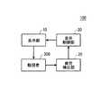
図1は、観視者200に画像を表示する表示装置100の構成例を示す。表示装置100は、表示部10、疲労検出部20および表示制御部30を備える。表示部10は、例えば液晶ディスプレイ等の表示デバイスに、視差を有する右眼用画像および左眼用画像を用いた立体的画像を表示する。また、表示部10は、表示デバイスに2次元画像を表示してもよい。 FIG. 1 shows a configuration example of a
立体的画像を表示する場合、表示部10は、右眼用画像および左眼用画像を同時に表示してよい。この場合、表示部10は、右眼用画像からの光を観視者200の右眼位置に集光させ、左眼用画像からの光を観視者200の左眼位置に集光させてよい。例えば表示部10は、パララックスバリア方式、または、レンチキュラ方式により、右眼用画像および左眼用画像の光を観視者200の右眼位置および左眼位置に集光させる。また、表示部10は、右眼用画像および左眼用画像からの光の偏光方向を異ならせてよい。この場合、表示装置100は、観視者200の右眼に対して右眼用画像の光を通過させ、観視者200の左眼に対して左眼用画像の光を通過させる偏光メガネを更に有する。当該偏光メガネは観視者200に装着される。 When displaying a stereoscopic image, the
また、表示部10は、右眼用画像および左眼用画像を時分割で交互に表示してもよい。この場合、表示装置100は、観視者200に装着され、観視者200の右眼および左眼に対して交互に光を通過させるシャッタ付メガネを更に備える。当該シャッタ付メガネは、表示部10が右眼用画像を表示するタイミングで観視者200の右眼に対して光を通過させ、且つ、左眼に対しては光を通過させない。また、当該シャッタ付メガネは、表示部10が左眼用画像を表示するタイミングで観視者200の右眼に対して光を通過させず、且つ、左眼に対して光を通過させる。 The
疲労検出部20は、観視者200の眼疲労量を示す疲労情報を取得する。疲労検出部20は、観視者200の眼の画像から検出されるまばたき回数、眼の開口面積等のように、観視者200の眼疲労量を直接的に示す疲労情報を取得してよい。また、疲労検出部20は、観視者200に観視させた画像の履歴、観視者200に画像を観視させた時間の長さ等のように、観視者200の眼疲労量を間接的に示す疲労情報を取得してもよい。 The
表示制御部30は、疲労検出部20が検出した眼疲労量が予め定められた閾値を越えた場合に、画像の視差を変化させずに、観視者200の視点位置を奥行き方向に変化させる変化画像を表示部10に表示させる。変化画像は、心理的な影響により観視者200の視点位置を奥行き方向に変化させる画像要素を含んでよい。例えば変化画像は、時間経過と共に徐々に大きさが変化する画像要素を含んでよく、時間経過と共に徐々に明るさが変化する画像要素を含んでよい。 The
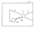
図2は、表示制御部30が表示部10に表示させる変化画像14の一例を示す。本例の表示部10は、右眼用画像および左眼用画像として同一の2次元画像を表示する。つまり、変化画像14は、立体的画像ではなく、2次元画像として表示される。 FIG. 2 shows an example of the change image 14 that the
表示制御部30は、変化画像14として、時間経過と共に大きさおよび位置が変化する画像を表示してよい。また表示制御部30は、表示部10に、変化画像14とあわせて補助画像12を表示させてもよい。補助画像12は、遠近法(または透視図法)による描画される画像であってよく、消失点11を有する。 The
表示制御部30は、時間経過と共に、初期位置から補助画像12に沿って位置が変化する変化画像14を表示させてよい。例えば、変化画像14は、初期位置(例えば変化画像14−1の位置)から消失点11に向かって位置が変化してよく、初期位置(例えば変化画像14−2の位置)から消失点11とは逆方向に位置が変化してもよい。 The
変化画像14を消失点11に向かって移動させる場合、表示制御部30は、変化画像14の大きさを徐々に小さくしてよい。また、変化画像14を消失点11に向かって移動させる場合、表示制御部30は、変化画像14の明るさを徐々に暗くしてよい。 When the change image 14 is moved toward the
変化画像14を消失点11から離れる方向に移動させる場合、表示制御部30は、変化画像14の大きさを徐々に大きくしてよい。また、変化画像14を消失点11から離れる方向に移動させる場合、表示制御部30は、変化画像14の明るさを徐々に明るくしてよい。 When the change image 14 is moved in a direction away from the vanishing
このような変化画像14を表示することで、観視する画像から得られる心理的な影響で、観視者200の視点位置(ピント位置)を奥行き方向に変化させることができる。例えば、変化画像14が小さくなりながら消失点11に向かって移動する場合、観視者200は、変化画像14が遠ざかっているように感じ、視点位置が奥行き方向に変化する。このため、観視者200の眼の筋緊張を緩和することができ、観視者200の眼疲労量を低減することができる。 By displaying such a change image 14, the viewpoint position (focus position) of the
なお、表示制御部30は、変化画像14を表示部10に表示させるとともに、所定の音響を観視者200に与えてもよい。例えば表示制御部30は、変化画像14の大きさを徐々に小さくする場合に、観視者200に与える音響量を徐々に小さくする。また、表示制御部30は、変化画像14の大きさを徐々に大きくする場合に、観視者200に与える音響量を徐々に大きくする。このような処理により、観視者200に与える心理的影響を大きくし、観視者200の視点位置を奥行き方向に変化させやすくすることができる。 The
また、表示制御部30は、変化画像14を表示部10に表示させる場合、観視者200の右眼または左眼のいずれか一方に変化画像14を表示してよい。例えば観視者200がシャッタ付きメガネを装着している場合、表示制御部30は、シャッタ付きメガネを制御して、変化画像14を表示させる期間、右眼または左眼のいずれか一方に画像を通過させ、他方の眼への画像を遮蔽する。 Further, when displaying the change image 14 on the
それぞれの眼に変化画像14を表示させる期間は、変化画像14を、予め定められた態様で変化させるのに要する期間であってよい。それぞれの眼に変化画像14を表示させる期間は、例えば数秒から数十秒程度であってよい。表示制御部30は、予め定められた回数、変化画像14の態様を繰り返し変化させて表示させてよい。 The period during which the change image 14 is displayed on each eye may be a period required to change the change image 14 in a predetermined manner. The period during which the change image 14 is displayed on each eye may be, for example, about several seconds to several tens of seconds. The
また、観視者200が偏光メガネを装着している場合、表示制御部30は、表示部10が表示する右眼用画像および左眼用画像の一方に変化画像14を表示させ、他方の画像として黒べたの画像を表示させてよい。また、表示部10がレンチキュラ方式またはパララックスバリア方式の場合には、表示制御部30は、表示部10が表示する右眼用画像および左眼用画像の一方に変化画像14を表示させ、他方の画像として黒べたの画像を表示させてよい。片眼ずつ変化画像14を表示させることで、観視者200の視点位置に対する両眼の輻輳角による影響を低減することができる。このため、心理的な影響を強調して、観視者200の視点位置を変化させやすくすることができる。 When the
なお、表示装置100は、観視者200等に指定された視聴用画像を観視者200に表示する。表示制御部30は、疲労検出部20が検出した眼疲労量が予め定められた閾値を越えた場合に、表示部10における視聴用画像の表示を停止させ、図2に示したような変化画像14を表示部10に表示させてよい。この場合、変化画像14を所定の期間表示した後、表示制御部30は、停止した箇所から視聴用画像の表示を再開する。 The
また、表示制御部30は、疲労検出部20が検出した眼疲労量が予め定められた閾値を越えた場合に、視聴用画像および変化画像14の双方を表示部10に表示させてもよい。この場合、表示制御部30は、表示部10において視聴用画像が表示される領域の外に、変化画像14を表示させてよく、視聴用画像に重畳して変化画像14を表示させてもよい。視聴用画像に重畳して変化画像14を表示させる場合、例えば視聴用画像の中央に、上述した変化画像14を表示させてよい。 The
図3は、表示部10における表示例を示す。本例の表示部10は、視聴用画像16および変化画像14の双方を表示する。本例の変化画像14は、視聴用画像16が表示される領域の外に表示される。 FIG. 3 shows a display example on the
表示制御部30は、変化画像14を表示させる場合において視聴用画像16が表示される領域を、変化画像14を表示させない場合における視聴用画像16が表示される領域より小さくしてよい。例えば変化画像14を表示させない場合、視聴用画像16は、表示部10の表示面の全面に表示される。そして、変化画像14を表示する場合、図3に示すように視聴用画像16は縮小されて、表示部10の表示面のいずれかの領域に表示されてよい。例えば視聴用画像16は、表示部10の表示面の端部に表示される。 The
また、表示制御部30は、変化画像14を表示させる場合における視聴用画像16の輝度を、変化画像14を表示させない場合における視聴用画像16の輝度よりも低くしてよい。また、表示制御部30は、変化画像14を表示させる場合における視聴用画像16のコントラストを、変化画像14を表示させない場合における視聴用画像16のコントラストよりも小さくしてよい。このような処理により、観視者200を、変化画像14に注目させることができる。 Further, the
また、表示制御部30は、変化画像14を表示させない場合の通常の視聴用画像16として、視差を有する右眼用画像および左眼用画像を表示部10に表示させ、変化画像14を表示させる場合の視聴用画像16として、視差を有さない右眼用画像および左眼用画像(すなわち同一の右眼用画像および左眼用画像)を表示部10に表示させてよい。また、表示制御部30は、変化画像14を表示させる場合に、右眼用画像および左眼用画像の一方のみを表示部10に表示させてもよい。また、表示制御部30は、変化画像14を表示部10に表示する場合、視聴用画像16および変化画像14を、観視者200の右眼または左眼の片方ずつに、数秒から数十秒程度の期間選択的に表示してよい。 Further, the
図4は、疲労検出部20の構成例を示す。疲労検出部20は、基準格納部22、眼画像取得部24、および、疲労測定部26を有する。眼画像取得部24は、表示部10を観視する観視者200の眼の画像を取得する。眼画像取得部24は、取得した眼の画像から、所定期間内における、観視者200のまばたき回数、観視者200の眼の開口面積、観視者200の瞳孔面積の変化速度、または、輻輳角の変化速度等の疲労情報を取得してよい。 FIG. 4 shows a configuration example of the
基準格納部22は、眼画像取得部24が出力する疲労情報と比較すべき基準情報を格納する。基準格納部22は、それぞれの観視者200について、基準となる眼の動作の基準画像を予め格納してよい。 The
基準格納部22には、疲労が蓄積していない観視者200において測定した基準情報を格納することが好ましい。例えば、基準格納部22は、表示部10が予め定められた期間以上、画像を表示していないことを条件として、観視者200の眼の動作の基準画像を撮像して、所定期間内における観視者200のまばたき回数、観視者200の眼の開口面積、観視者200の瞳孔面積の変化速度、または、輻輳角の変化速度等の疲労情報を取得してよい。 The
また、基準格納部22は、表示部10が画像表示を開始した直後における、観視者200の眼の画像から得られる基準情報を格納してもよい。また、表示装置100は、観視者200により視聴することが指定された画像を表示する前に、基準情報を取得するための画像を表示してもよい。当該画像は、例えば輝度値、輝度値の変化パターン、コントラスト等の特性が予め定められた画像である。 The
また、基準格納部22は、疲労が蓄積した状態の観視者200において測定した基準情報を格納してもよい。例えば、基準格納部22は、過去において、表示部10が予め定められた期間以上画像を表示した後に撮像した観視者200の眼の動作の画像から得られる基準情報を格納する。 Moreover, the reference |
また、基準格納部22は、観視者200が長時間画像を観視して、観視者200のまばたき回数の増大、瞳孔面積の変化速度の劣化等が飽和した状態での基準情報を取得してもよい。 In addition, the
疲労測定部26は、眼画像取得部24から取得した情報と、基準格納部22が格納した基準情報とを比較して、観視者200の疲労が基準値を越えたか否かを判定する。例えば疲労測定部26は、眼画像取得部24から取得したまばたき回数が、基準格納部22が格納した基準値を越えたか否かを判定してよい。疲労測定部26は、観視者200の疲労が基準値を越えたと判定した場合に、その旨を表示制御部30に通知する。 The
また、表示部10が動画像を表示する場合において、疲労測定部26は、直前の予め定められた期間内において表示部10が表示した右眼用画像および左眼用画像の特性を示す情報を含む疲労情報を取得してもよい。この場合、疲労検出部20は、眼画像取得部24を有さなくともよい。画像の特性とは、画像のフレーム間における、各被写体(画像要素)の視差量の変化、輝度の変化、および、コントラストの変化の少なくとも一つを含んでよい。 When the
また、疲労測定部26は、当該期間における当該変化量の絶対値の積分値を取得してもよい。例えば、当該期間内において、表示部10が点滅するような画像を表示する場合、輝度の変化の積分値が大きくなり、観視者200の眼疲労の蓄積が大きいと評価される。また、疲労測定部26は、直前の所定期間内において表示部10が表示した画像の輝度の平均値、または、表示部10が画像を連続して表示している期間等の情報を取得してもよい。 Moreover, the
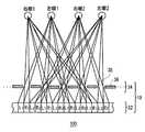
図5は、表示部10の構成例を示す。本例の表示部10は、異なる位置にいる観視者200毎に、独立して右眼用画像および左眼用画像を表示する。本例では、二人の観視者200の各眼(右眼1、左眼1、右眼2、左眼2)に、対応する右眼用画像および左眼用画像を表示する場合を説明する。 FIG. 5 shows a configuration example of the
表示部10は、表示デバイス32およびバリア部34を含む。表示デバイス32は、観視者200の各眼(右眼1、左眼1、右眼2、左眼2)に対応する、右眼用画像R1、左眼用画像L1、右眼用画像R2、左眼用画像L2の各画素列を、所定の順序で水平方向に配列した画像を表示する。例えば、表示デバイス32は、左眼1に対応する左眼用画像L1の画素列、右眼1に対応する右眼用画像R1の画素列、左眼2に対応する左眼用画像L2の画素列、右眼2に対応する右眼用画像R2の画素列を、この順序で配列した画像を表示する。 The
バリア部34は、表示デバイス32の画像表示面に対向して配置される。バリア部34は、複数の通過部38と、複数の遮蔽部36を有する。バリア部34は、パララックスバリアであってよい。 The
複数の遮蔽部36は、複数の通過部38が、水平方向において所定の周期で配列されるように設けられる。ここで、水平方向とは、通過部38及び遮蔽部36が交互に配列される配列方向を指す。例えば、それぞれの通過部38の横方向の幅をWとして、視点数をNとすると、複数の通過部38は、W×Nの周期で配列されてよい。図5に示すように、通過部38の横方向の幅が1画素分であり、視点数が4の場合、通過部38は、横方向において4画素毎に配置される。それぞれの通過部38の間には、遮蔽部36が設けられる。 The plurality of shielding
このような構成により、複数の通過部38は、各視点に対して、表示デバイス32が表示した複数の画素列のうち対応する画素列からの光を通過して表示させる。一方、複数の遮蔽部36は、各視点に対して、表示デバイス32が表示した複数の画素列のうち対応しない画素列からの光を遮蔽する。 With such a configuration, the plurality of
例えば、左眼1の位置からは、対応する画素列L1を観察することができるが、それ以外の画素列L2、R1、R2は遮蔽部36によって遮られ、観察することはできない。他の視点からも同様に、対応する画素列を観察することができるが、それ以外の画素列を観察することができない。このような構成により、複数の観視者200に対して、それぞれの右眼用画像および左眼用画像を提供できる。 For example, the corresponding pixel column L1 can be observed from the position of the left eye 1, but the other pixel columns L2, R1, and R2 are blocked by the shielding
なお表示部10の構成は、当該構成に限定されない。例えば表示部10は、バリア部34に代えてレンチキュラーレンズを用いることによっても、複数の観視者200に対して、それぞれの右眼用画像および左眼用画像を提供することができる。 The configuration of the
また、表示部10が左眼用画像L1、右眼用画像R1、左眼用画像L2および右眼用画像R2を時分割で表示して、それぞれの観視者200に装着されるシャッタ付メガネにより対応する画像を各観視者200に観視させることによっても、複数の観視者200に対して、それぞれの右眼用画像および左眼用画像を提供できる。また、表示部10が、それぞれの画像について偏光方向を異ならせて表示して、それぞれの観視者200に装着される偏光メガネにより対応する画像を各観視者200に観視させることによっても、複数の観視者200に対して、それぞれの右眼用画像および左眼用画像を提供できる。 Further, the
本例において疲労検出部20は、観視者200毎に疲労を測定することが好ましい。本例において表示制御部30は、それぞれの観視者200の疲労に基づいて、対応する観視者200に変化画像14を表示するか否かを制御する。これにより、それぞれの観視者200の疲労に応じて、観視者200毎に変化画像14を表示することができる。 In this example, it is preferable that the
なお、複数の観視者200に対して画像を表示する場合において、疲労測定部26は、それぞれの観視者200について予め定められたパラメータを測定する。表示制御部30は、それぞれの観視者200のパラメータの変化と、複数の観視者200のパラメータの変化の平均とに基づいて、それぞれの観視者200に対して変化画像14を表示するか否かを制御する。 In addition, when displaying an image with respect to the plurality of
例えば疲労測定部26は、画像表示を開始した直後の所定期間内におけるまばたき回数に対する、直近の所定期間内におけるまばたき回数の増加割合を、それぞれの観視者200について測定する。表示制御部30は、全ての観視者200における当該増加割合の平均値を算出する。そして、表示制御部30は、それぞれの観視者200における当該増加割合が、当該増加割合の全観視者200の平均値に対してどれだけ乖離しているかを算出する。表示制御部30は、当該乖離の度合いが基準値を越えた場合に、対応する観視者200に変化画像14を表示する。また、疲労測定部26は、当該パラメータとして、観視者200の体温、脈拍等の生体情報を測定してもよい。 For example, the
図6は、表示装置100の動作例のフローチャートを示す。まず表示部10において、観視者200等が指定した視聴用画像を表示する(S300)。例えば視聴用画像とは、テレビ、映画、ゲーム等の画像であってよい。なお、表示部10は、当該視聴用画像が終了した場合には、画像表示を終了してよい(S302)。 FIG. 6 shows a flowchart of an operation example of the
視聴用画像が終了していない場合、疲労検出部20は、観視者200の眼疲労を検出する(S304)。疲労検出部20が検出した眼疲労量が、所定の閾値を越えていない場合、表示部10は、視聴用画像の表示を継続する(S306)。疲労検出部20が検出した眼疲労量が、所定の閾値を越えた場合、表示制御部30は、変化画像14を表示部10に表示させる(S308)。このとき表示部10は、視聴用画像の表示を継続してよく、停止してもよい。 If the viewing image has not ended, the
表示制御部30は、変化画像14を所定の期間表示させた場合に、変化画像14の表示を終了させる(S310)。この場合において、表示部10は、通常の視聴用画像の表示を再開する。 When the change image 14 is displayed for a predetermined period, the
以上、本発明を実施の形態を用いて説明したが、本発明の技術的範囲は上記実施の形態に記載の範囲には限定されない。上記実施の形態に、多様な変更または改良を加えることが可能であることが当業者に明らかである。その様な変更または改良を加えた形態も本発明の技術的範囲に含まれ得ることが、特許請求の範囲の記載から明らかである。 As mentioned above, although this invention was demonstrated using embodiment, the technical scope of this invention is not limited to the range as described in the said embodiment. It will be apparent to those skilled in the art that various modifications or improvements can be added to the above-described embodiment. It is apparent from the scope of the claims that the embodiments added with such changes or improvements can be included in the technical scope of the present invention.
特許請求の範囲、明細書、および図面中において示した装置、システム、プログラム、および方法における動作、手順、ステップ、および段階等の各処理の実行順序は、特段「より前に」、「先立って」等と明示しておらず、また、前の処理の出力を後の処理で用いるのでない限り、任意の順序で実現しうることに留意すべきである。特許請求の範囲、明細書、および図面中の動作フローに関して、便宜上「まず、」、「次に、」等を用いて説明したとしても、この順で実施することが必須であることを意味するものではない。 The order of execution of each process such as operations, procedures, steps, and stages in the apparatus, system, program, and method shown in the claims, the description, and the drawings is particularly “before” or “prior to”. It should be noted that the output can be realized in any order unless the output of the previous process is used in the subsequent process. Regarding the operation flow in the claims, the description, and the drawings, even if it is described using “first”, “next”, etc. for convenience, it means that it is essential to carry out in this order. It is not a thing.
10・・・表示部、12・・・補助画像、14・・・・変化画像、16・・・視聴用画像、20・・・疲労検出部、22・・・基準格納部、24・・・眼画像取得部、26・・・疲労測定部、30・・・表示制御部、32・・・表示デバイス、34・・・バリア部、36・・・遮蔽部、38・・・通過部、100・・・表示装置、200・・・観視者DESCRIPTION OF
Claims (13)
Translated fromJapanese前記画像を前記観視者に表示する表示部と、
前記観視者の眼疲労量を検出する疲労検出部と、
前記疲労検出部が検出した前記眼疲労量が予め定められた閾値を越えた場合に、前記観視者の視点位置を奥行き方向に変化させる変化画像を前記表示部に表示させる表示制御部と
を備える表示装置。A display device for displaying an image to a viewer,
A display unit for displaying the image to the viewer;
A fatigue detection unit for detecting an eye fatigue amount of the viewer;
A display control unit that causes the display unit to display a change image that changes the viewpoint position of the viewer in the depth direction when the eye fatigue amount detected by the fatigue detection unit exceeds a predetermined threshold; A display device provided.
前記表示制御部は、視差を変化させずに前記観視者の視点位置を奥行き方向に変化させる前記変化画像を前記表示部に表示させる
請求項1に記載の表示装置。The display unit displays a right-eye image and a left-eye image having parallax,
The display device according to claim 1, wherein the display control unit causes the display unit to display the change image that changes the viewpoint position of the viewer in the depth direction without changing parallax.
前記表示制御部は、前記疲労検出部が検出した前記眼疲労量が予め定められた閾値を越えた場合に、前記表示部における前記視聴用画像の表示を停止させ、前記変化画像を前記表示部に表示させる
請求項1または2に記載の表示装置。The display device displays a predetermined viewing image to the viewer,
The display control unit stops display of the viewing image on the display unit when the eye fatigue amount detected by the fatigue detection unit exceeds a predetermined threshold, and displays the change image on the display unit. The display device according to claim 1 or 2.
前記表示制御部は、前記疲労検出部が検出した前記眼疲労量が予め定められた閾値を越えた場合に、前記視聴用画像および前記変化画像の双方を前記表示部に表示させる
請求項1または2に記載の表示装置。The display device displays a predetermined viewing image to the viewer,
The display control unit causes the display unit to display both the viewing image and the change image when the eye fatigue amount detected by the fatigue detection unit exceeds a predetermined threshold. 2. The display device according to 2.
請求項4に記載の表示装置。The display device according to claim 4, wherein the display control unit displays the change image outside an area where the viewing image is displayed on the display unit.
請求項5に記載の表示装置。The said display control part makes the area | region where the said image for viewing in the case of displaying the said change image smaller than the area | region where the image for viewing in the case of not displaying the said change image is displayed. Display device.
請求項5に記載の表示装置。The display device according to claim 5, wherein the display control unit lowers the luminance of the viewing image when the change image is displayed lower than the luminance of the viewing image when the change image is not displayed.
前記疲労検出部は、直前の予め定められた期間内において前記表示部に表示した前記右眼用画像および前記左眼用画像の特性を示す特性情報に基づいて、前記観視者の眼疲労量を検出する
請求項2に記載の表示装置。The display unit displays a moving image,
The fatigue detection unit, based on characteristic information indicating characteristics of the right-eye image and the left-eye image displayed on the display unit within a predetermined period immediately before the eye fatigue amount of the viewer The display device according to claim 2.
請求項8に記載の表示装置。The fatigue detection unit is at least one of a change in parallax amount, a change in luminance, and a change in contrast between frames of the right-eye image and the left-eye image displayed on the display unit. The display device according to claim 8, wherein an eye fatigue amount of the viewer is detected based on the display.
前記疲労検出部は、前記観視者毎に前記眼疲労量を検出し、
前記表示制御部は、前記眼疲労量が予め定められた閾値を越えた前記観視者に対応する前記表示部の領域に前記変化画像を表示させる
請求項1から9のいずれか一項に記載の表示装置。The display unit displays an image for each viewer at different positions,
The fatigue detection unit detects the amount of eye fatigue for each viewer,
The said display control part displays the said change image on the area | region of the said display part corresponding to the said viewer whose said eye fatigue amount exceeded the predetermined threshold value. Display device.
請求項1から10のいずれか一項に記載の表示装置。The fatigue detection unit measures a predetermined parameter for each of the viewers, and changes the parameters of the viewers and an average of the parameter changes of the viewers. The display device according to claim 1, wherein the eye fatigue amount of each viewer is detected based on the display device.
前記観視者について、眼の動作の基準画像を予め格納する基準格納部と、
前記表示部が表示した画像を観視している前記観視者の眼の動作の画像を取得する眼画像取得部と、
前記眼画像取得部が取得した画像と、前記基準格納部が格納した前記基準画像とを比較して、前記観視者の前記眼疲労量を測定する疲労測定部と
を有する請求項1から10のいずれか一項に記載の表示装置。The fatigue detection unit
For the viewer, a reference storage unit that stores in advance a reference image of eye movement;
An eye image acquisition unit that acquires an image of the eye movement of the viewer who is viewing the image displayed by the display unit;
The fatigue measurement unit that measures the amount of eye fatigue of the viewer by comparing the image acquired by the eye image acquisition unit with the reference image stored by the reference storage unit. The display device according to any one of the above.
前記観視者の眼疲労量を検出する疲労検出段階と、
前記疲労検出段階において検出した前記眼疲労量が予め定められた閾値を越えた場合に、前記観視者の視点位置を奥行き方向に変化させる変化画像を、表示部に表示させる表示制御段階と
を備える表示方法。A display method for displaying an image to a viewer,
A fatigue detection step of detecting an eye fatigue amount of the viewer;
A display control step of displaying, on a display unit, a change image that changes the viewpoint position of the viewer in the depth direction when the eye fatigue amount detected in the fatigue detection step exceeds a predetermined threshold value. A display method provided.
Priority Applications (1)
| Application Number | Priority Date | Filing Date | Title |
|---|---|---|---|
| JP2010159999AJP2012022150A (en) | 2010-07-14 | 2010-07-14 | Display device and display method |
Applications Claiming Priority (1)
| Application Number | Priority Date | Filing Date | Title |
|---|---|---|---|
| JP2010159999AJP2012022150A (en) | 2010-07-14 | 2010-07-14 | Display device and display method |
Publications (1)
| Publication Number | Publication Date |
|---|---|
| JP2012022150Atrue JP2012022150A (en) | 2012-02-02 |
Family
ID=45776483
Family Applications (1)
| Application Number | Title | Priority Date | Filing Date |
|---|---|---|---|
| JP2010159999APendingJP2012022150A (en) | 2010-07-14 | 2010-07-14 | Display device and display method |
Country Status (1)
| Country | Link |
|---|---|
| JP (1) | JP2012022150A (en) |
Cited By (8)
| Publication number | Priority date | Publication date | Assignee | Title |
|---|---|---|---|---|
| JP2012119739A (en)* | 2010-11-29 | 2012-06-21 | Sony Corp | Information processing apparatus, information processing method and program |
| CN103414908A (en)* | 2013-08-05 | 2013-11-27 | 深圳Tcl新技术有限公司 | 3D glasses, 3D television and image field depth controlling method of 3D television |
| WO2017003054A1 (en)* | 2015-06-30 | 2017-01-05 | 삼성전자 주식회사 | Method for displaying 3d image and device for same |
| US10531066B2 (en) | 2015-06-30 | 2020-01-07 | Samsung Electronics Co., Ltd | Method for displaying 3D image and device for same |
| JP2021064006A (en)* | 2014-11-28 | 2021-04-22 | 株式会社半導体エネルギー研究所 | Display system |
| US11320900B2 (en) | 2016-03-04 | 2022-05-03 | Magic Leap, Inc. | Current drain reduction in AR/VR display systems |
| KR20220115816A (en)* | 2016-03-25 | 2022-08-18 | 매직 립, 인코포레이티드 | Virtual and augmented reality systems and methods |
| US11966055B2 (en) | 2018-07-19 | 2024-04-23 | Magic Leap, Inc. | Content interaction driven by eye metrics |
Citations (9)
| Publication number | Priority date | Publication date | Assignee | Title |
|---|---|---|---|---|
| JPH11511316A (en)* | 1996-06-07 | 1999-09-28 | フィリップス エレクトロニクス ネムローゼ フェンノートシャップ | 3D image display drive |
| JP2001222338A (en)* | 2000-02-07 | 2001-08-17 | Doko Kagi Kofun Yugenkoshi | Method for preventing damage of eye due to long-term operation of personal computer |
| JP2003047636A (en)* | 2001-05-28 | 2003-02-18 | Nikon Corp | Eye fatigue relief device |
| JP2004236241A (en)* | 2003-01-31 | 2004-08-19 | Nikon Corp | Display device |
| JP2004357760A (en)* | 2003-06-02 | 2004-12-24 | Sophia Co Ltd | Game machine |
| JP2006133794A (en)* | 2005-12-07 | 2006-05-25 | Fujitsu Ten Ltd | Video signal processing method and video signal processing device |
| WO2006093074A1 (en)* | 2005-03-01 | 2006-09-08 | Matsushita Electric Industrial Co., Ltd. | Electronic display medium and screen display control method used for electronic display medium |
| JP2006267578A (en)* | 2005-03-24 | 2006-10-05 | Seiko Epson Corp | Stereoscopic image display apparatus and method |
| JP2009106578A (en)* | 2007-10-31 | 2009-05-21 | Hiroshi Imamura | Asthenopia relieving system and program |
- 2010
- 2010-07-14JPJP2010159999Apatent/JP2012022150A/enactivePending
Patent Citations (9)
| Publication number | Priority date | Publication date | Assignee | Title |
|---|---|---|---|---|
| JPH11511316A (en)* | 1996-06-07 | 1999-09-28 | フィリップス エレクトロニクス ネムローゼ フェンノートシャップ | 3D image display drive |
| JP2001222338A (en)* | 2000-02-07 | 2001-08-17 | Doko Kagi Kofun Yugenkoshi | Method for preventing damage of eye due to long-term operation of personal computer |
| JP2003047636A (en)* | 2001-05-28 | 2003-02-18 | Nikon Corp | Eye fatigue relief device |
| JP2004236241A (en)* | 2003-01-31 | 2004-08-19 | Nikon Corp | Display device |
| JP2004357760A (en)* | 2003-06-02 | 2004-12-24 | Sophia Co Ltd | Game machine |
| WO2006093074A1 (en)* | 2005-03-01 | 2006-09-08 | Matsushita Electric Industrial Co., Ltd. | Electronic display medium and screen display control method used for electronic display medium |
| JP2006267578A (en)* | 2005-03-24 | 2006-10-05 | Seiko Epson Corp | Stereoscopic image display apparatus and method |
| JP2006133794A (en)* | 2005-12-07 | 2006-05-25 | Fujitsu Ten Ltd | Video signal processing method and video signal processing device |
| JP2009106578A (en)* | 2007-10-31 | 2009-05-21 | Hiroshi Imamura | Asthenopia relieving system and program |
Cited By (20)
| Publication number | Priority date | Publication date | Assignee | Title |
|---|---|---|---|---|
| US9955138B2 (en) | 2010-11-29 | 2018-04-24 | Saturn Licensing Llc | Information processing apparatus, information processing method and program |
| JP2012119739A (en)* | 2010-11-29 | 2012-06-21 | Sony Corp | Information processing apparatus, information processing method and program |
| CN103414908A (en)* | 2013-08-05 | 2013-11-27 | 深圳Tcl新技术有限公司 | 3D glasses, 3D television and image field depth controlling method of 3D television |
| JP7200343B2 (en) | 2014-11-28 | 2023-01-06 | 株式会社半導体エネルギー研究所 | Display device |
| JP2021064006A (en)* | 2014-11-28 | 2021-04-22 | 株式会社半導体エネルギー研究所 | Display system |
| JP6996011B2 (en) | 2014-11-28 | 2022-01-17 | 株式会社半導体エネルギー研究所 | Display system |
| JP2022058358A (en)* | 2014-11-28 | 2022-04-12 | 株式会社半導体エネルギー研究所 | Display device |
| WO2017003054A1 (en)* | 2015-06-30 | 2017-01-05 | 삼성전자 주식회사 | Method for displaying 3d image and device for same |
| US10531066B2 (en) | 2015-06-30 | 2020-01-07 | Samsung Electronics Co., Ltd | Method for displaying 3D image and device for same |
| US11775062B2 (en) | 2016-03-04 | 2023-10-03 | Magic Leap, Inc. | Current drain reduction in AR/VR display systems |
| US11402898B2 (en) | 2016-03-04 | 2022-08-02 | Magic Leap, Inc. | Current drain reduction in AR/VR display systems |
| US11320900B2 (en) | 2016-03-04 | 2022-05-03 | Magic Leap, Inc. | Current drain reduction in AR/VR display systems |
| US12229337B2 (en) | 2016-03-04 | 2025-02-18 | Magic Leap, Inc. | Current drain reduction in AR/VR display systems |
| KR20220115816A (en)* | 2016-03-25 | 2022-08-18 | 매직 립, 인코포레이티드 | Virtual and augmented reality systems and methods |
| US11467408B2 (en) | 2016-03-25 | 2022-10-11 | Magic Leap, Inc. | Virtual and augmented reality systems and methods |
| KR102550587B1 (en)* | 2016-03-25 | 2023-06-30 | 매직 립, 인코포레이티드 | Virtual and augmented reality systems and methods |
| KR20230098725A (en)* | 2016-03-25 | 2023-07-04 | 매직 립, 인코포레이티드 | Virtual and augmented reality systems and methods |
| US11966059B2 (en) | 2016-03-25 | 2024-04-23 | Magic Leap, Inc. | Virtual and augmented reality systems and methods |
| KR102667713B1 (en)* | 2016-03-25 | 2024-05-20 | 매직 립, 인코포레이티드 | Virtual and augmented reality systems and methods |
| US11966055B2 (en) | 2018-07-19 | 2024-04-23 | Magic Leap, Inc. | Content interaction driven by eye metrics |
Similar Documents
| Publication | Publication Date | Title |
|---|---|---|
| JP2012022150A (en) | Display device and display method | |
| JP4046121B2 (en) | Stereoscopic image display apparatus and method | |
| US9041782B2 (en) | Multiple-viewer auto-stereoscopic 3D display apparatus | |
| CN101668220B (en) | Adjustable 3D display with parallax barrier | |
| JP6061852B2 (en) | Video display device and video display method | |
| US8610711B2 (en) | Device for three-dimensional image display using viewing zone enlargement | |
| US20120249951A1 (en) | Optotype presenting apparatus | |
| US20120062556A1 (en) | Three-dimensional image display apparatus, three-dimensional image processor, three-dimensional image display method, and computer program product | |
| KR101413244B1 (en) | Apparatus for 3-dimensional displaying using modified common viewing zone | |
| WO2018058914A1 (en) | Naked-eye 3d display device and display method thereof | |
| US8596792B2 (en) | Optotype presenting apparatus | |
| WO2011043022A1 (en) | Image display device and image display method | |
| KR101960897B1 (en) | Stereoscopic image display device and displaying method thereof | |
| US20140139647A1 (en) | Stereoscopic image display device | |
| WO2015180402A1 (en) | Display control method, apparatus and system | |
| WO2017202059A1 (en) | Liquid crystal lens, 3d display panel and control method thereof | |
| CN206260048U (en) | A kind of bore hole 3D display devices | |
| CN101547373A (en) | Method for avoiding blind zones in optical grating three-dimensional display screen | |
| JPH08327948A (en) | Stereoscopic image display method and stereoscopic image display device | |
| US20120268455A1 (en) | Image processing apparatus and method | |
| CN103969836A (en) | A viewing angle extension method for multi-viewpoint autostereoscopic display | |
| JPWO2013030905A1 (en) | Image processing apparatus, stereoscopic image display apparatus, and image processing method | |
| JP2012227653A (en) | Imaging apparatus and imaging method | |
| JP2009104198A (en) | Stereoscopic image display device and stereoscopic image display method | |
| KR20100064525A (en) | Apparatus and method for testing align in three-dimensional device |
Legal Events
| Date | Code | Title | Description |
|---|---|---|---|
| A621 | Written request for application examination | Free format text:JAPANESE INTERMEDIATE CODE: A621 Effective date:20130520 | |
| A977 | Report on retrieval | Free format text:JAPANESE INTERMEDIATE CODE: A971007 Effective date:20131225 | |
| A131 | Notification of reasons for refusal | Free format text:JAPANESE INTERMEDIATE CODE: A131 Effective date:20140225 | |
| A02 | Decision of refusal | Free format text:JAPANESE INTERMEDIATE CODE: A02 Effective date:20140701 |