JP2012014909A - Plane light source device - Google Patents
Plane light source deviceDownload PDFInfo
- Publication number
- JP2012014909A JP2012014909AJP2010148865AJP2010148865AJP2012014909AJP 2012014909 AJP2012014909 AJP 2012014909AJP 2010148865 AJP2010148865 AJP 2010148865AJP 2010148865 AJP2010148865 AJP 2010148865AJP 2012014909 AJP2012014909 AJP 2012014909A
- Authority
- JP
- Japan
- Prior art keywords
- light
- guide plate
- prism
- source device
- light source
- Prior art date
- Legal status (The legal status is an assumption and is not a legal conclusion. Google has not performed a legal analysis and makes no representation as to the accuracy of the status listed.)
- Pending
Links
- 238000009792diffusion processMethods0.000claimsabstractdescription52
- 230000007423decreaseEffects0.000claimsdescription3
- 230000015556catabolic processEffects0.000abstractdescription2
- 238000006731degradation reactionMethods0.000abstractdescription2
- 239000004973liquid crystal related substanceSubstances0.000description17
- 239000011347resinSubstances0.000description10
- 229920005989resinPolymers0.000description10
- 238000010586diagramMethods0.000description9
- 239000000463materialSubstances0.000description8
- 229920005668polycarbonate resinPolymers0.000description5
- 239000004431polycarbonate resinSubstances0.000description5
- 230000004048modificationEffects0.000description4
- 238000012986modificationMethods0.000description4
- 239000002390adhesive tapeSubstances0.000description3
- 230000006866deteriorationEffects0.000description3
- 238000009826distributionMethods0.000description3
- 230000003287optical effectEffects0.000description3
- 239000004925Acrylic resinSubstances0.000description2
- 229920000178Acrylic resinPolymers0.000description2
- 239000000470constituentSubstances0.000description2
- 230000000694effectsEffects0.000description2
- 238000000034methodMethods0.000description2
- 229920003229poly(methyl methacrylate)Polymers0.000description2
- 239000004926polymethyl methacrylateSubstances0.000description2
- OAICVXFJPJFONN-UHFFFAOYSA-NPhosphorusChemical compound[P]OAICVXFJPJFONN-UHFFFAOYSA-N0.000description1
- 229920000297RayonPolymers0.000description1
- 230000002411adverseEffects0.000description1
- 238000005520cutting processMethods0.000description1
- 239000011888foilSubstances0.000description1
- 239000011521glassSubstances0.000description1
- 238000004519manufacturing processMethods0.000description1
- 239000002184metalSubstances0.000description1
- 230000002093peripheral effectEffects0.000description1
- 239000004417polycarbonateSubstances0.000description1
- 229920000515polycarbonatePolymers0.000description1
- 239000002964rayonSubstances0.000description1
- 239000000758substrateSubstances0.000description1
Images


Classifications
- G—PHYSICS
- G02—OPTICS
- G02F—OPTICAL DEVICES OR ARRANGEMENTS FOR THE CONTROL OF LIGHT BY MODIFICATION OF THE OPTICAL PROPERTIES OF THE MEDIA OF THE ELEMENTS INVOLVED THEREIN; NON-LINEAR OPTICS; FREQUENCY-CHANGING OF LIGHT; OPTICAL LOGIC ELEMENTS; OPTICAL ANALOGUE/DIGITAL CONVERTERS
- G02F1/00—Devices or arrangements for the control of the intensity, colour, phase, polarisation or direction of light arriving from an independent light source, e.g. switching, gating or modulating; Non-linear optics
- G02F1/01—Devices or arrangements for the control of the intensity, colour, phase, polarisation or direction of light arriving from an independent light source, e.g. switching, gating or modulating; Non-linear optics for the control of the intensity, phase, polarisation or colour
- G02F1/13—Devices or arrangements for the control of the intensity, colour, phase, polarisation or direction of light arriving from an independent light source, e.g. switching, gating or modulating; Non-linear optics for the control of the intensity, phase, polarisation or colour based on liquid crystals, e.g. single liquid crystal display cells
- G02F1/133—Constructional arrangements; Operation of liquid crystal cells; Circuit arrangements
- G02F1/1333—Constructional arrangements; Manufacturing methods
- G02F1/1335—Structural association of cells with optical devices, e.g. polarisers or reflectors
- G—PHYSICS
- G02—OPTICS
- G02B—OPTICAL ELEMENTS, SYSTEMS OR APPARATUS
- G02B6/00—Light guides; Structural details of arrangements comprising light guides and other optical elements, e.g. couplings
- G02B6/0001—Light guides; Structural details of arrangements comprising light guides and other optical elements, e.g. couplings specially adapted for lighting devices or systems
- G02B6/0011—Light guides; Structural details of arrangements comprising light guides and other optical elements, e.g. couplings specially adapted for lighting devices or systems the light guides being planar or of plate-like form
- G02B6/0013—Means for improving the coupling-in of light from the light source into the light guide
- G02B6/0023—Means for improving the coupling-in of light from the light source into the light guide provided by one optical element, or plurality thereof, placed between the light guide and the light source, or around the light source
- G02B6/0028—Light guide, e.g. taper
- G—PHYSICS
- G02—OPTICS
- G02B—OPTICAL ELEMENTS, SYSTEMS OR APPARATUS
- G02B6/00—Light guides; Structural details of arrangements comprising light guides and other optical elements, e.g. couplings
- G02B6/0001—Light guides; Structural details of arrangements comprising light guides and other optical elements, e.g. couplings specially adapted for lighting devices or systems
- G02B6/0011—Light guides; Structural details of arrangements comprising light guides and other optical elements, e.g. couplings specially adapted for lighting devices or systems the light guides being planar or of plate-like form
- G02B6/0013—Means for improving the coupling-in of light from the light source into the light guide
- G02B6/0015—Means for improving the coupling-in of light from the light source into the light guide provided on the surface of the light guide or in the bulk of it
- G02B6/0016—Grooves, prisms, gratings, scattering particles or rough surfaces
- G—PHYSICS
- G02—OPTICS
- G02B—OPTICAL ELEMENTS, SYSTEMS OR APPARATUS
- G02B6/00—Light guides; Structural details of arrangements comprising light guides and other optical elements, e.g. couplings
- G02B6/0001—Light guides; Structural details of arrangements comprising light guides and other optical elements, e.g. couplings specially adapted for lighting devices or systems
- G02B6/0011—Light guides; Structural details of arrangements comprising light guides and other optical elements, e.g. couplings specially adapted for lighting devices or systems the light guides being planar or of plate-like form
- G02B6/0013—Means for improving the coupling-in of light from the light source into the light guide
- G02B6/0015—Means for improving the coupling-in of light from the light source into the light guide provided on the surface of the light guide or in the bulk of it
- G02B6/0018—Redirecting means on the surface of the light guide
- G—PHYSICS
- G02—OPTICS
- G02B—OPTICAL ELEMENTS, SYSTEMS OR APPARATUS
- G02B6/00—Light guides; Structural details of arrangements comprising light guides and other optical elements, e.g. couplings
- G02B6/0001—Light guides; Structural details of arrangements comprising light guides and other optical elements, e.g. couplings specially adapted for lighting devices or systems
- G02B6/0011—Light guides; Structural details of arrangements comprising light guides and other optical elements, e.g. couplings specially adapted for lighting devices or systems the light guides being planar or of plate-like form
- G02B6/0033—Means for improving the coupling-out of light from the light guide
- G02B6/0035—Means for improving the coupling-out of light from the light guide provided on the surface of the light guide or in the bulk of it
- G02B6/0038—Linear indentations or grooves, e.g. arc-shaped grooves or meandering grooves, extending over the full length or width of the light guide
- G—PHYSICS
- G02—OPTICS
- G02B—OPTICAL ELEMENTS, SYSTEMS OR APPARATUS
- G02B6/00—Light guides; Structural details of arrangements comprising light guides and other optical elements, e.g. couplings
- G02B6/0001—Light guides; Structural details of arrangements comprising light guides and other optical elements, e.g. couplings specially adapted for lighting devices or systems
- G02B6/0011—Light guides; Structural details of arrangements comprising light guides and other optical elements, e.g. couplings specially adapted for lighting devices or systems the light guides being planar or of plate-like form
- G02B6/0033—Means for improving the coupling-out of light from the light guide
- G02B6/005—Means for improving the coupling-out of light from the light guide provided by one optical element, or plurality thereof, placed on the light output side of the light guide
- G02B6/0053—Prismatic sheet or layer; Brightness enhancement element, sheet or layer
Landscapes
- Physics & Mathematics (AREA)
- General Physics & Mathematics (AREA)
- Optics & Photonics (AREA)
- Nonlinear Science (AREA)
- Mathematical Physics (AREA)
- Chemical & Material Sciences (AREA)
- Crystallography & Structural Chemistry (AREA)
- Planar Illumination Modules (AREA)
Abstract
Description
Translated fromJapanese本発明は面光源装置に関し、たとえば液晶パネルを背面から照明するためのバックライトなどに用いられる面光源装置に関する。 The present invention relates to a surface light source device, for example, a surface light source device used for a backlight for illuminating a liquid crystal panel from the back.
エッジライト型の面光源装置では、平板状をした導光板の入光端面に対向させて光源を配置し、導光板の上面に拡散板やプリズムシートを重ねている。この面光源装置では、導光板の厚みが光源の高さに比べて小さいと、光源から発した光のうち入光端面から導光板に入射せず入光端面よりも外側へ逃げる光が増加し、光の利用効率が悪くなる。そのため、導光板の厚みは光源の高さとほぼ等しくなっている。 In the edge light type surface light source device, a light source is arranged to face a light incident end surface of a flat light guide plate, and a diffusion plate and a prism sheet are stacked on the upper surface of the light guide plate. In this surface light source device, when the thickness of the light guide plate is smaller than the height of the light source, the light emitted from the light source does not enter the light guide plate from the light incident end surface and escapes outward from the light incident end surface. , The light utilization efficiency will be worse. Therefore, the thickness of the light guide plate is approximately equal to the height of the light source.
このような面光源装置の全体厚みを薄くしようとすれば、光源の高さと導光板の厚みを薄くすることが考えられる。しかし、導光板の厚みを薄くできたとしても、光源には製造上の制約があり、その高さをより小さくすることは困難である。そのため、光源の高さと導光板の厚みを小さくする方法では、ある限度以下に面光源装置の厚みを薄くすることはできない。 In order to reduce the overall thickness of such a surface light source device, it is conceivable to reduce the height of the light source and the thickness of the light guide plate. However, even if the thickness of the light guide plate can be reduced, the light source has manufacturing restrictions, and it is difficult to reduce the height of the light source. Therefore, in the method of reducing the height of the light source and the thickness of the light guide plate, the thickness of the surface light source device cannot be reduced below a certain limit.
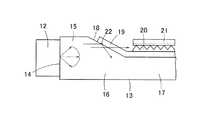
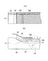
そこで、図1に示すように、入光端面14を備えた入光部15の厚みを光源12の高さとほぼ等しくし、導光板13の入光端面14と反対側に入光端面14よりも厚みの薄い平板状の導光板本体17を設け、入光部15と導光板本体17を連続させるようにして両者の間にくさび形をした光導入部16を形成した面光源装置11が提案されている。この面光源装置11では、入光端面14の厚みと導光板本体17の厚みの差を拡散板19やプリズムシート20、21の合計厚みにほぼ等しくしておけば、導光板本体17の上面に拡散板19及びプリズムシート20、21を重ねることにより、面光源装置11の全体厚みを薄くすることができる。また、この面光源装置11では、光源12の高さと入光端面14の厚みがほぼ等しくなっているので、光源12から出射した光は、効率よく入光端面14から入光部15へ取り込まれる。さらに、光導入部16の上面が傾斜面18となっていて厚みの大きな入光部15と厚みの薄い導光板本体17が光導入部16を介して滑らかに接続されているので、入光部15に入射した光は、光導入部16の傾斜面18と下面で全反射しながら導光板本体17へ導光され、導光板13における漏れ光を少なくできる。 Therefore, as shown in FIG. 1, the thickness of the
しかし、このような面光源装置を液晶パネルのバックライトとして用いる場合には、迷光が液晶パネルに入射するのを防ぐため、光導入部の上面と導光板本体の上面外周部を遮光テープ(主に、黒色粘着シート)で覆って、その上面に液晶パネルを重ねる。そのため、遮光テープが光導入部の傾斜面にくっつくことがあり、遮光テープが傾斜面にくっつくと、傾斜面に入射した導光板内の光が遮光テープに吸収され、面光源装置の輝度が低下したり、輝度むらを生じたりするおそれがある。 However, when such a surface light source device is used as a backlight of a liquid crystal panel, in order to prevent stray light from being incident on the liquid crystal panel, a light shielding tape (main In addition, the liquid crystal panel is overlaid on the upper surface. For this reason, the light shielding tape may stick to the inclined surface of the light introducing portion. When the light shielding tape adheres to the inclined surface, the light in the light guide plate incident on the inclined surface is absorbed by the light shielding tape, and the luminance of the surface light source device is lowered. Or uneven brightness may occur.
そこで、特許文献1に開示された面光源装置では、図2に示すように、導光板本体17の上面に重ねられたシートのうち一番下に位置する拡散板19の端を延長して傾斜面18の上面に重ね、延長した拡散板19によって遮光テープが傾斜面18にくっつくのを防いでいる。 Therefore, in the surface light source device disclosed in Patent Document 1, as shown in FIG. 2, the end of the
しかしながら、特許文献1に開示されたような面光源装置では、つぎのような理由により光導入部16の傾斜面18から光が漏れやすかった。
A) 導光板内では、光は導光板の上面と下面で全反射を繰り返しながら導光するが、導光板が平板の場合には、全反射を繰り返しても導光板の上面又は下面に入射する光の入射角が変化しないので、導光板の上面や下面から光は漏れにくい。
一方、特許文献1のように傾斜面18を有する導光板13の場合には、導光板13の下面と傾斜面18で全反射するたびに傾斜面18に再入射する光の入射角が小さくなるので、入光端面14から離れるにつれて全反射の臨界角(以下では、全反射の臨界角を単に臨界角という。)付近の光が多くなり、傾斜面18から漏れる光の割合が多くなる。
B) 光源からの出射光はほぼランバート分布となっているため、光源から出射される光のうちで発光強度がもっとも強いのは、光源の発光面中央の光であり、しかも発光面に垂直な方向の光である。したがって、導光板内を導光する光のうちで最大強度となるのは、導光板の中央を入光端面と垂直に進む光である(実際の導光板では、導光板の傾斜面や導光板下面の凹凸パターンの影響により光源から離れるに従って光の分布は均一化されるが、入光部付近では、一般に、導光板の中央を入光端面に垂直な方向に進む光の強度が大きい)。
特許文献1の面光源装置11では、傾斜面18の表面に拡散板19が延びているので、傾斜面18のうち拡散板19の密着している領域に光が入射すると、図2に示すように、界面における屈折率差が小さいために拡散板19を通って光が外部へ漏れてしまう。しかも、上記のような最大強度付近の光も傾斜面18に入射するので、光源12の全光量に対する漏れ光の割合も大きくなる。
なお、実際には、拡散板19の裏面には微細な凹凸が存在するため、拡散板19の延長部分の裏面全体が傾斜面18に密着する訳ではなく、空気層22を含む部分では光が全反射されるが、最大強度付近の光も傾斜面18に入射するので、一部の光が拡散板19を通って漏れるだけでもかなりの漏れ光となる。
C) 特許文献1の面光源装置11では、導光板13の傾斜面18が平らであるために拡散板19の角が接触することで傾斜面18に微細な傷が付きやすく、この傷によって傾斜面18から光が漏れやすくなる。特に、傾斜面18の導光板本体側の端部付近に微細な傷が発生すると、光の漏れが大きくなる。However, in the surface light source device as disclosed in Patent Document 1, light is likely to leak from the
A) In the light guide plate, light is guided while repeating total reflection on the upper and lower surfaces of the light guide plate. However, when the light guide plate is a flat plate, it is incident on the upper or lower surface of the light guide plate even if total reflection is repeated. Since the incident angle of light does not change, light hardly leaks from the upper and lower surfaces of the light guide plate.
On the other hand, in the case of the
B) Since the emitted light from the light source has a Lambertian distribution, the light emitted from the light source has the strongest emission intensity at the center of the light emitting surface of the light source and perpendicular to the light emitting surface. Directional light. Therefore, the light having the maximum intensity among the light guided in the light guide plate is light that travels perpendicularly to the light incident end surface in the center of the light guide plate (in an actual light guide plate, the inclined surface of the light guide plate or the light guide plate). Although the light distribution becomes uniform as the distance from the light source increases due to the influence of the uneven pattern on the lower surface, the intensity of light traveling generally in the direction perpendicular to the light incident end surface in the vicinity of the light incident portion is large in the vicinity of the light incident portion.
In the surface
Actually, since there are fine irregularities on the back surface of the
C) In the surface
このようにして傾斜面18から光が漏れると、図3に示すように、拡散板19を透過して拡散された光が、プリズムシート20、21の端面や両シート20、21間に入光する。そして、両シート20、21間に入射した光は、プリズムシート21によって上方へ曲げられ、一部は遮光テープ23で吸収されるが、残る一部の光は遮光テープ23の開口(導光板本体17の発光領域)まで届き、余分な光となってホットスポット(つまり、不均一に明るい輝点)を生じる。また、プリズムシート20、21内にその端面から入射した光は、プリズムシート20、21の内部を導光しながら徐々に上方へ射出されるので、遮光テープ23の開口内で細長い輝度むら(輝線)になる。この結果、面光源装置11の発光領域にホットスポットや輝度むらが発生し、面光源装置11の発光品位が低下する問題があった。また、傾斜面18から光の漏れが大きくなると、発光領域の輝度低下を引き起こすことになる。 When light leaks from the
なお、傾斜面18の傾斜角が緩やかである場合には、光の漏れが少ないため、拡散板19による光拡散効果もあってホットスポットや輝度むらは目立ちにくく、発光品位の低下は軽微である。しかし、近年、面光源装置の薄型化傾向のなかで、傾斜面の傾斜角も急になってきており、上記のような発光品位の低下や輝度の低下が顕著となってきている。 In addition, when the inclination angle of the
本発明は、上記のような技術的課題に鑑みてなされたものであって、その目的とするところは、導光板の傾斜面から漏れた光によるホットスポットや輝度むらなどの発光品位の低下を防止することのできる面光源装置を提供することにある。 The present invention has been made in view of the technical problems as described above. The object of the present invention is to reduce the light emission quality such as hot spots and luminance unevenness due to light leaking from the inclined surface of the light guide plate. An object of the present invention is to provide a surface light source device that can be prevented.
本発明に係る面光源装置は、入光端面と、前記入光端面の厚みよりも薄い導光板本体と、前記導光板本体と連続するように形成されていて前記入光端面側から前記導光板本体側へ向けて次第に厚みが薄くなった光導入部とを有する導光板、前記入光端面と対向する位置に配置された光源、前記導光板本体の発光側の面に置かれた拡散板及び1枚又は複数枚のプリズムシート、および、前記導光板本体の発光領域を除く領域において前記拡散板及び前記プリズムシートよりも上方に配置された遮光シートを備え、1枚又は複数枚の前記プリズムシートのうち少なくとも1枚のプリズムシートを前記光導入部の表面に向けて延出させたことを特徴としている。 The surface light source device according to the present invention includes a light incident end surface, a light guide plate main body that is thinner than the light incident end surface, and a light guide plate that is formed to be continuous with the light guide plate main body from the light incident end surface side. A light guide plate having a light introducing portion that gradually decreases in thickness toward the main body side, a light source disposed at a position facing the light incident end surface, a diffusion plate placed on a light emitting side surface of the light guide plate main body, and One or a plurality of prism sheets, and a light shielding sheet disposed above the diffusion plate and the prism sheet in a region excluding a light emitting region of the light guide plate main body, the one or a plurality of prism sheets At least one prism sheet is extended toward the surface of the light introducing portion.
本発明の面光源装置は、入光端面よりも薄くなった導光板本体の上に拡散板やプリズムシートを重ねることで面光源装置全体の厚みを薄くしたものであるが、このような形態の導光板では、平板状でない光導入部の表面から光が漏れて迷光となり、ホットスポットや輝度むらなどによって発光品位を低下させるおそれがある。 The surface light source device of the present invention is a device in which the thickness of the entire surface light source device is reduced by stacking a diffusion plate or a prism sheet on the light guide plate body that is thinner than the light incident end surface. In the light guide plate, light leaks from the surface of the light introduction portion that is not flat and becomes stray light, which may reduce the light emission quality due to hot spots or uneven brightness.
しかし、本発明の面光源装置では、光導入部の表面にプリズムシートを延出させて光導入部の表面をプリズムシートで覆っているので、光導入部の表面から漏れた光はプリズムシートに入射し、プリズムシートにほぼ垂直な方向へ曲げられて遮光シートで吸収される。したがって、光導入部から漏れた光が迷光となってホットスポットや輝度むらを生じさせるのを防止でき、面光源装置の発光品位を向上させることができる。 However, in the surface light source device of the present invention, since the prism sheet is extended on the surface of the light introducing portion and the surface of the light introducing portion is covered with the prism sheet, the light leaking from the surface of the light introducing portion is applied to the prism sheet. Incident light is bent in a direction substantially perpendicular to the prism sheet and absorbed by the light shielding sheet. Therefore, it is possible to prevent the light leaked from the light introducing portion from becoming stray light and causing hot spots and luminance unevenness, and the light emission quality of the surface light source device can be improved.
本発明に係る面光源装置のある実施態様は、前記導光板本体の発光側の面に前記拡散板が置かれ、当該拡散板の上に、前記拡散板と対向する面と反対側の面にプリズムを形成された2枚の前記プリズムシートが重ねられ、2枚の前記プリズムシートのうち少なくとも一方のプリズムシートが前記光導入部の表面に向けて延出していることを特徴としている。かかる実施態様では、導光板本体の表面で拡散板の上に重ねられたプリズムシートが光導入部側へ延出されて光導入部の表面を覆っているので、プリズムシートが光導入部の表面に密着しにくくなっている。そのため、光導入部内の光がその表面から漏れにくくなり、迷光が発生しにくくなって発光品位の低下を抑制できる。また、光導入部からの漏れ光が少なくなるので、導光板本体における発光輝度を高めることができる。 In an embodiment of the surface light source device according to the present invention, the diffusion plate is placed on a light-emitting side surface of the light guide plate body, and on the diffusion plate, on a surface opposite to the surface facing the diffusion plate. Two prism sheets on which prisms are formed are overlapped, and at least one of the two prism sheets extends toward the surface of the light introducing portion. In such an embodiment, the prism sheet overlaid on the diffusion plate on the surface of the light guide plate main body is extended to the light introducing portion side to cover the surface of the light introducing portion, so that the prism sheet is the surface of the light introducing portion. It becomes difficult to adhere to. Therefore, the light in the light introducing portion is less likely to leak from the surface, stray light is less likely to be generated, and a reduction in light emission quality can be suppressed. In addition, since the leakage light from the light introducing portion is reduced, the light emission luminance in the light guide plate body can be increased.
また、この実施態様においては、2枚の前記プリズムシートが前記光導入部の表面で積層されていてもよい。光導入部の表面に2枚のプリズムシートが積層されていると、光導入部の表面から漏れた光はプリズムシートを2回通過することになり、プリズムシートに垂直な方向へ偏向されて遮光シートで吸収される光の割合が増加する。 In this embodiment, the two prism sheets may be laminated on the surface of the light introducing portion. When two prism sheets are stacked on the surface of the light introducing portion, light leaking from the surface of the light introducing portion passes through the prism sheet twice, and is deflected in a direction perpendicular to the prism sheet to block light. The proportion of light absorbed by the sheet increases.
さらに、この実施態様においては、前記光導入部の表面に向けて延出された前記プリズムシートと前記光導入部の表面との間に空気層が設けられていることが好ましい。プリズムシートと光導入部の表面との間に空気層を設ければ、導光板の表面から光が漏れにくくなり、面光源装置の発光品位の低下を抑制するとともに発光輝度を向上させることができる。 Furthermore, in this embodiment, it is preferable that an air layer is provided between the prism sheet extended toward the surface of the light introducing portion and the surface of the light introducing portion. If an air layer is provided between the prism sheet and the surface of the light introducing portion, light is less likely to leak from the surface of the light guide plate, and the light emission quality of the surface light source device can be prevented from being lowered and the light emission luminance can be improved. .
本発明に係る面光源装置の別な実施態様は、前記導光板本体の発光側の面に、前記導光板本体と対向する面にプリズムを形成された1枚の前記プリズムシートが置かれ、当該プリズムシートの上に前記拡散板が重ねられていることを特徴としている。かかる実施態様では、下面にプリズムを形成されたプリズムシートを用いているので、プリズムシートを透過した光を効率よくプリズムシートに垂直な方向へ偏向させることができ、より多くの光量を遮光シートで吸収させることができる。 In another embodiment of the surface light source device according to the present invention, one prism sheet having a prism formed on a surface facing the light guide plate main body is placed on the light emitting side surface of the light guide plate main body, The diffusion plate is overlaid on a prism sheet. In such an embodiment, since the prism sheet having the prism formed on the lower surface is used, the light transmitted through the prism sheet can be efficiently deflected in the direction perpendicular to the prism sheet, and a larger amount of light can be transmitted by the light shielding sheet. Can be absorbed.
本発明に係る面光源装置のさらに別な実施態様は、前記拡散板が、前記光導入部と前記導光板本体の境界よりも離れた位置に配置されていることを特徴としている。かかる実施態様によれば、拡散板の端面が光導入部から離れるので、光導入部から漏れた光が拡散板の端面から拡散板内に入射しにくくなり、発光品位の低下を抑制できる。 Still another embodiment of the surface light source device according to the present invention is characterized in that the diffusion plate is disposed at a position away from a boundary between the light introducing portion and the light guide plate body. According to such an embodiment, since the end face of the diffusion plate is separated from the light introducing portion, the light leaked from the light introducing portion becomes difficult to enter the diffusion plate from the end face of the diffusion plate, and the deterioration of the light emission quality can be suppressed.
本発明に係る面光源装置のさらに別な実施態様は、1枚又は複数枚の前記プリズムシートのうち、延出された少なくとも一枚のプリズムシートが、そのプリズム稜線方向が前記入光端面に垂直な方向に対して30°以上90°以下の角度をなすように配置されていることを特徴としている。なお、ここでプリズム稜線方向が入光端面に垂直な方向に対してなす角度は、プリズム稜線の回転方向によらず、入光端面に垂直な方向から測った角度が0°以上90°以下となるように定義する。かかる実施態様によれば、光導入部の表面から漏れた光がプリズムシートによって回帰反射されにくくなる。したがって、プリズムシートで回帰反射された光が再び導光板内に戻って発光領域から出射するのを防ぐことができ、発光品位の低下を抑制できる。 In another embodiment of the surface light source device according to the present invention, at least one prism sheet extended out of one or a plurality of the prism sheets has a prism ridge line direction perpendicular to the light incident end face. It is characterized by being arranged at an angle of 30 ° or more and 90 ° or less with respect to any direction. Here, the angle formed by the prism ridge direction with respect to the direction perpendicular to the light incident end face is 0 ° or more and 90 ° or less as measured from the direction perpendicular to the light incident end face regardless of the rotation direction of the prism ridge line. Define to be According to such an embodiment, the light leaking from the surface of the light introducing portion is less likely to be recursively reflected by the prism sheet. Therefore, it is possible to prevent the light that has been retro-reflected by the prism sheet from returning to the inside of the light guide plate and exiting from the light emitting region, and to suppress the deterioration of the light emitting quality.
本発明に係る面光源装置のさらに別な実施態様は、前記光導入部の発光側の面を傾斜面としたことを特徴としている。かかる実施態様によれば、導光板本体の発光側の面を窪ませることができ、拡散板やプリズムシートをそこに納めることが可能になる。 Yet another embodiment of the surface light source device according to the present invention is characterized in that the light-emitting side surface of the light introducing portion is an inclined surface. According to such an embodiment, the light-emitting side surface of the light guide plate body can be recessed, and the diffusion plate and the prism sheet can be accommodated therein.
本発明に係る面光源装置のさらに別な実施態様は、前記光導入部の発光側の面を複数の平面によって膨らんだように形成したことを特徴としている。かかる実施態様によればプリズムシートの角を光導入部の表面から浮かせることができ、プリズムシートの角によって光導入部の表面に傷がつくのを防ぐことができ、傷のついた箇所から漏れる光を少なくできる。 Still another embodiment of the surface light source device according to the present invention is characterized in that the light-emitting side surface of the light introducing portion is formed so as to swell by a plurality of planes. According to such an embodiment, the corner of the prism sheet can be lifted from the surface of the light introducing portion, the surface of the light introducing portion can be prevented from being scratched by the corner of the prism sheet, and leaks from the scratched portion. Light can be reduced.
本発明に係る面光源装置のさらに別な実施態様は、前記光導入部の発光側の面を曲面によって膨らんだように形成したことを特徴としている。かかる実施態様でもプリズムシートの角を光導入部の表面から浮かせることができ、プリズムシートの角によって光導入部の表面に傷がつくのを防ぐことができ、傷のついた箇所から漏れる光を少なくできる。 Still another embodiment of the surface light source device according to the present invention is characterized in that the light-emitting side surface of the light introducing portion is formed so as to swell with a curved surface. Even in such an embodiment, the corner of the prism sheet can be floated from the surface of the light introducing portion, the surface of the light introducing portion can be prevented from being scratched by the corner of the prism sheet, and light leaking from the scratched portion can be prevented. Less.
なお、本発明における前記課題を解決するための手段は、以上説明した構成要素を適宜組み合せた特徴を有するものであり、本発明はかかる構成要素の組合せによる多くのバリエーションを可能とするものである。 The means for solving the above-described problems in the present invention has a feature in which the above-described constituent elements are appropriately combined, and the present invention enables many variations by combining such constituent elements. .
以下、添付図面を参照しながら本発明の好適な実施形態を説明する。ただし、本発明は以下の実施形態に限定されるものでなく、本発明の要旨を逸脱しない範囲において種々設計変更することができる。 Hereinafter, preferred embodiments of the present invention will be described with reference to the accompanying drawings. However, the present invention is not limited to the following embodiments, and various design changes can be made without departing from the gist of the present invention.
(第1の実施形態)
まず、図4及び図5を参照して本発明の実施形態1による面光源装置31の構成を説明する。図4は面光源装置31の概略断面図である。図5は面光源装置31の分解斜視図である。(First embodiment)
First, the configuration of the surface
図4に示すように、面光源装置31は、反射板32、フレーム33、導光板34、複数個の光源35、フレキシブルプリント基板36、拡散板37、2枚のプリズムシート38a及び38b、遮光テープ39(遮光シート)などからなる。 As shown in FIG. 4, the surface
図4に示すように、光源35(LED発光素子)は、蛍光体を含んだ透光性の樹脂44内に青色発光LEDチップ43を封止し、当該樹脂44の前面を除く面を白色樹脂45によって覆ったサイドビュータイプのものである。LEDチップ43が発光すると、LEDチップ43から出射された青色光が擬似的な白色光に変換されながら、樹脂44の前面(発光窓46)から前方へ出射される。また、LEDチップ43から出射された光の一部は、樹脂44と白色樹脂45の界面で反射された後、発光窓46から前方へ出射される。 As shown in FIG. 4, the light source 35 (LED light-emitting element) has a blue light-emitting
複数個の光源35は、フレキシブルプリント基板36の下面に実装されており、一定のピッチで一列に並んでいる。 The plurality of
たとえば、サイドビュータイプの光源35は、厚み0.4mmの日亜化学工業製NSSW204を用いることができ、フレキシブルプリント基板36は厚み0.1mmのものを用いることができる。 For example, the side view
導光板34は、ポリカーボネイト樹脂やポリメチルメタクリレート(PMMA)樹脂などの屈折率の高い透光性樹脂によって成形されている。導光板34の端面には、導光板34の内部に光を導入するための入光端面41が形成されており、入光端面41の高さは光源35の発光窓46の高さよりも大きくなっている。入光端面41を有する入光部47は均一な厚みを有しており、入光部47と反対側には入光部47よりも厚みの薄い平板状の導光板本体49が設けられ、入光部47と導光板本体49を連続させるようにして両者の間にくさび形をした光導入部48が形成されている。導光板34においては導光板本体49が大部分の面積を占めており、導光板本体49の下面には、その内部を導光する光を全反射又は拡散させて導光板本体49の上面(光出射面42)から上方へ出射させるための微細な偏向パターン40(拡散手段)が多数形成されている。また、光導入部48の上面は、入光部47の上面から導光板本体49の上面へ向けて下り傾斜した傾斜面50となっている。 The
たとえば導光板34はポリカーボネイト樹脂によって成形されており、入光部47の厚さは0.43mm、光導入部48の傾斜面50の傾斜角は約10°、導光板本体49の厚みは0.20mmとなっている。 For example, the
フレーム33は、導光板34の入光部47と同程度の厚みを有する樹脂シート(たとえば、ポリカーボネイト樹脂のシート)をカッティングしたものであって、図5に示すように、導光板34を納めて位置決めするための開口51を有している。また、開口51の端には、フレキシブルプリント基板36の下面に実装された光源35を位置決めするための凹部52が光源35と同じピッチで設けられている。 The
反射板32は、白色シートや金属箔などの反射率の高い材料で形成され、あるいは多層膜(ESR)などの反射機構で形成されている。たとえば、厚み0.065mmの3M製ESRを用いることができる。反射板32は、導光板34の下面から漏れた光を反射させて導光板34に再入射させ、光の利用効率を向上させるものである。 The
図4に示すように、反射板32の上面外周部を、両面粘着テープ53によってフレーム33の下面に接着する。そして、フレーム33の開口51内に導光板34を納め、各光源35の発光窓46を導光板34の入光端面41に対向させるようにして各凹部52に光源35を納めて位置決めし、両面粘着テープ54(たとえば、厚み0.03mmの日東電工製No.5603)によってフレキシブルプリント基板36の下面をフレーム33の上面と導光板34の入光部47の上面に接着する。この結果、フレキシブルプリント基板36と反射板32はフレーム33に固定され、導光板34の裏面に反射板32が対向し、導光板34の入光部47は反射板32とフレキシブルプリント基板36に挟み込まれる。 As shown in FIG. 4, the outer peripheral portion of the upper surface of the reflecting
なお、入光部47の厚みは光源35の高さよりも大きくても小さくてもよいが、組み立てられた状態においては、光源35の発光窓46は入光端面41上端よりも上に出ず、下端よりも下に出ないように配置されなければならない。また、光源35の下面は、導光板34の裏面よりも引っ込んでいて反射板32との間に隙間が生じても差し支えない。 Although the thickness of the
しかして、光源35を点灯させたとき、光源35から出射された光は、入光端面41から導光板34内に導入され、導光板34の上面と下面の間で全反射を繰り返しながら導光板34内を導光する。そして、導光途中において偏向パターン40で全反射または拡散されて光出射面42へ向けて臨界角よりも小さな入射角で入射した光は、光出射面42から外部へ出射される。 Thus, when the
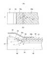
導光板本体49の上面には拡散板37と2枚のプリズムシート38a、38bが重ねて載置され、遮光テープ39で縁を押さえられる。拡散板37としては、たとえば厚み0.047mmのツジデン製D122LS4を用いることができる。拡散板37は、傾斜面50へはみ出ないようにして導光板本体49の上面に重ねられる。すなわち、拡散板37の端は、傾斜面50の下端(導光板本体49の上面との間の境界)よりも引っ込んだ位置に配置される。拡散板37の端を引っ込める程度としては、傾斜面50の下端から漏れた光が拡散板37の端面に入射しにくくなっていればよい。 A
プリズムシート38a、38bは、導光板34と反対側を向いた面(上面)に頂角が90°の断面三角形状をした直線状のプリズムを一定ピッチで平行に配列したものである。プリズムシート38a、38bとしては、たとえば厚み0.062mmの3M製TBEF2−Tを用いることができる。2枚のプリズムシート38a、38bは、シート面に垂直な方向から見たとき、プリズム稜線方向が互いに直交するように配置されている。また、プリズムシート38a、38bは、シート面に垂直な方向から見たとき、それぞれのプリズム稜線方向が入光端面41に垂直な垂線Cとなす角度φ1、φ2が45°となるように配置されている(図6(A)参照)。 The
また、上下に重ねられたプリズムシート38b、38aのうち、下側のプリズムシート38aの端部は傾斜面50の上方へ向けて延出し、傾斜面50の大部分を覆っている。ただし、プリズムシート38aの端部下面と傾斜面50との間には空気層56が挟み込まれており、プリズムシート38aと傾斜面50との密着面積はできるだけ小さくなるようにすることが好ましい。また、プリズムシート38aの端部の延出長さは、プリズムシート38aの上端が入光部47の上面を含む水平面よりも上に飛び出ない程度で、できるだけ長くすることが望ましい。一方、上側のプリズムシート38bの端部は、プリズムシート38aの傾斜部分に重ならないように配置することが望ましい。 Of the
なお、上記の構成とは反対に、下側のプリズムシート38aを傾斜面50の下端よりも引っ込め、上側のプリズムシート38bを傾斜面50の上方へ延出させるようにしてもよい。また、場合によっては、上下のプリズムシート38b、38aをいずれも傾斜面50の上方へ延出させてもよい(後述する)。 In contrast to the above configuration, the
遮光テープ39は黒色粘着テープである。遮光テープ39としては、たとえば厚み0.05mmの寺岡製作所製7045(0.05)黒HFを使用することができる。遮光テープ39には、導光板本体49の発光領域(有効領域)においてプリズムシート38bを露出させるために窓55が開口されている。遮光テープ39は、フレキシブルプリント基板36の上面とプリズムシート38bの上面の外周部全周に貼り付けられており、さらにフレキシブルプリント基板36と反対側においてフレーム33の上面に貼り付けられている。こうして、拡散板37、プリズムシート38a、38bは遮光テープ39によって保持されている。 The
このような構造の面光源装置31では、傾斜面50の上へ延出されているプリズムシート38aは拡散板37によって持ち上げられているので、傾斜面50とプリズムシート38aの下面との間に空気層56が生じる。空気層56に接した導光板材料における臨界角は、樹脂層(拡散板37又はプリズムシート38a)に密着した導光板材料における臨界角よりも小さいので、プリズムシート38aの下に空気層56が生じることで光が漏れにくくなる。特に、傾斜面50の下端部は、導光板34内で一番光量が多く、しかも導光板34の裏面や傾斜面50で何度か全反射した光が多くて漏れ出る光の割合が多いが、この領域には確実に空気層56が形成されるので、光の漏れを少なく抑えることができる。したがって、面光源装置31によれば、傾斜面50からの漏れ光による光損失が少なくなって発光領域における輝度が向上する。また、傾斜面50における光の漏れが少なくなるので、傾斜面50から漏れた光が迷光となって発光領域に達することによるホットスポットや輝度むらも低減される。 In the surface
しかし、傾斜面50とプリズムシート38aの間に空気層56が存在していても、傾斜面50に立てた法線に対する角度が空気層56に対する臨界角(たとえば、導光板34がポリカーボネイト製である場合には、この臨界角は約39°となる。)よりも小さくなる方向で入光部47内に入射した光は、傾斜面50に入射したときには傾斜面50から漏れる。 However, even if the
また、図6(B)に示すように、傾斜面50に対して臨界角よりも大きな入射角θ1で入射した光L1は傾斜面50で全反射するが、傾斜面50で全反射した光L1も導光板34の下面で全反射することによって再度傾斜面50に入射する。傾斜面50の傾斜角をγとすれば、再度傾斜面50に入射するときの入射角は2γだけ小さくなるので、傾斜面50と裏面の間で何度か全反射した光は、図6(B)のL2、L3のように臨界角よりも小さな入射角θ2、θ3で傾斜面50に入射して傾斜面50から漏れ出る。 Further, as shown in FIG. 6B, the light L1 incident at an incident angle θ1 larger than the critical angle with respect to the
こうして傾斜面50から漏れ出た光は、図6(B)に示すように、プリズムシート38aの下面からプリズムシート38aを通過してプリズムシート38aに垂直な方向へ光路を曲げられ、プリズムシート38aに垂直な方向へ導かれる。よって、傾斜面50から漏れた光は、遮光テープ39によって吸収され、遮光テープ39の窓55まで届きにくくなる。図6(B)に即して言えば、光L2はプリズムシート38a、38bのプリズム稜線方向の傾きφ1、φ2(入光端面41に垂直な垂線Cに対する傾き)の影響を受け、プリズムシート38aを通過した光L2は、垂線Cを含みシート面に垂直な平面から斜めに外れて上方向へ向かい、遮光テープ39の下面に当たって吸収される。 As shown in FIG. 6B, the light leaking from the
傾斜面50の下端部Aには、傾斜面50や裏面で何度か全反射した光が入射するので、この領域Aは導光板34内で一番光量が多く、しかも光が漏れ易い。図6に示すように、領域Aから漏れる光L3は、光L2よりも窓55に近い場所で傾斜面50から漏れるが、上下2枚のプリズムシート38a、38bを通過することによって、光L2よりも垂直に近い方向へ曲げられるので、やはり光L3も窓55に届くことなく、遮光テープ39の下面に当たって吸収される。 Since light totally reflected several times on the
また、プリズムシート38aの下面が傾斜面50に密着していて空気層56が存在しない場合には、傾斜面50から漏れる光量が増加するが、この場合にも上記のようなプリズムシート38a、38bの働きによって、傾斜面50から漏れた光は遮光テープ39の下面に当たって吸収され、窓55から漏れにくくなる。 In addition, when the lower surface of the
この結果、面光源装置31では、発光領域にホットスポットや輝度むらが生じにくくなり、発光品位が向上する。 As a result, in the surface
さらに、傾斜面50に微細な傷が発生している場合には、そこから光が漏れやすくなるが、傾斜面50の大部分の領域、特に光量の多い下端部Aにはプリズムシート38aが接触しないので、光の漏れの原因となる傷がつきにくく、発光領域の輝度低下を小さくできる。 Further, when a minute scratch is generated on the
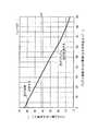
つぎに、傾斜面50の下端で漏れた光の挙動を簡略に考察することにより、拡散板37や遮光テープ39の配置を考える。図7は、傾斜面50に立てた法線Nに対してθ4の角度(入射角)で傾斜面50の下端に入射した光L4の挙動を示す。実際の導光板内の光は様々な光線方向と強度分布を持つので、一意的な取り扱いは困難であるが、代表的な光線追跡を簡略化して行うことにより、各要素の寸法関係を概略的に求めることができる。 Next, the arrangement of the
ここでは、最も光が漏れやすい部分である傾斜面50の下端からの漏れ光L4を考える。この光L4の傾斜面50への入射角θ4としては、空気層に対する導光板材料の臨界角よりも少し小さい値を想定している。具体的には、導光板材料をポリカーボネイト樹脂とすれば、空気層との界面における臨界角は約39°となるので、入射角θ4は臨界角より少し小さな35°とする。 Here, the leakage light L4 from the lower end of the
傾斜面50から漏れた光が拡散板37の端面に入射すると、拡散板37内を光が導光して従来例と同様に細長い輝度むらが発生するので、まず傾斜面50から漏れた光を拡散板37の端面に入射させないための条件を考える。傾斜面50から漏れた光が拡散板37の端面に入射しない条件を求めようとすれば、拡散板37に最も近い傾斜面50の下端から漏れた光を考えれば十分である。傾斜面50の傾斜角をγとし、導光板材料の屈折率をn1としたとき、傾斜面50の下端から漏れた光L4は、導光板本体49の上面に対して
90°−γ−arcsin(n1・sinθ4) …(数式1)
の角度をなす方向へ空気層56内を進む。拡散板37の厚みをfとすれば、この光L4が傾斜面50の下端を出てから空気層56を進んでプリズムシート38aの下面に達するまでに進む距離を水平方向へ射影した水平距離bは、
b=f・tan(κ) …(数式2)
ただし、κ=γ+arcsin(n1・sinθ4)
となる。したがって、傾斜面50の下端から拡散板37の端面までの水平距離cが数式2の水平距離bよりも大きければ、漏れ光L4は拡散板37を回避してプリズムシート38aに入射する。すなわち、
c > f・tan(κ) …(数式3)
であればよい。When the light leaked from the
It advances in the
b = f · tan (κ) (Formula 2)
However, κ = γ + arcsin (n1 · sinθ4)
It becomes. Therefore, if the horizontal distance c from the lower end of the
c> f · tan (κ) (Formula 3)
If it is.
入射角θ4を上記のように35°とし、傾斜面50の傾斜角をγ=10°、拡散板37の厚みをf=0.047mm、導光板材料(ポリカーボネイト樹脂)の屈折率をn1=1.59とすれば、κ=75.8°となるから、上記数式3は、
c > 0.186mm
となる。よって、たとえばc=0.20mmとすればよい。The incident angle θ4 is set to 35 ° as described above, the inclination angle of the
c> 0.186 mm
It becomes. Therefore, for example, c = 0.20 mm may be set.
つぎに、漏れ光L4を遮光テープ39の下面に当てて吸収させるための条件を考える。ここでは、プリズムシート38a、38bを簡略化して平坦なシートで置き換える。プリズムシート38aの下面に入射する光L4の入射角は、
γ+arcsin(n1・sinθ4)
であるから、プリズムシート38a、38bの屈折率をn2とすれば、プリズムシート38a、38b内を通過する光L4がプリズムシート38a、38bに垂直な方向となす角度(屈折角)は、
arcsin〔(1/n2)sin(κ)〕 …(数式4)
となる。よって、プリズムシート38a、38bの厚さをそれぞれg、hとすれば、傾斜面50の下端から光L4が遮光テープ39の下面に当たる点までの水平距離dは、
d=b+(g+h)×tan{arcsin〔(1/n2)sin(κ)〕} …(数式5)
ただし、κ=γ+arcsin(n1・sinθ4)
となる。実際には、プリズムシート38aを通過する光はそのプリズムによって垂直上方へ偏向され、プリズムシート38bのプリズムでも垂直上方へ偏向されるから、傾斜面50の下端から光L4が遮光テープ39の下面に当たる点までの水平距離は数式5で表したdよりも短くなる。したがって、傾斜面50の下端から漏れた光L4を遮光テープ39の下面で吸収させるためには、傾斜面50の下端から遮光テープ39の窓55の縁まで測った水平距離eが、このdの値よりも大きければ十分である。すなわち、
e > b+(g+h)×tan{arcsin〔(1/n2)sin(κ)〕} …(数式6)
であればよい。Next, a condition for absorbing the leaked light L4 against the lower surface of the
γ + arcsin (n1 · sinθ4)
Therefore, if the refractive index of the
arcsin [(1 / n2) sin (κ)] (Formula 4)
It becomes. Therefore, if the thicknesses of the
d = b + (g + h) × tan {arcsin [(1 / n2) sin (κ)]} (Formula 5)
However, κ = γ + arcsin (n1 · sinθ4)
It becomes. Actually, the light passing through the
e> b + (g + h) × tan {arcsin [(1 / n2) sin (κ)]} (Expression 6)
If it is.
水平距離bの値は0.186mmで、κの値は75.8°であったから、プリズムシート38a、38bがいずれもアクリル樹脂製であってその屈折率をn2=1.5とし、またその厚みがg=h=0.062mmであるとすれば、上記数式6は
e > 0.27mm
となる。よって、たとえばe=0.30mmとすればよい。Since the value of the horizontal distance b was 0.186 mm and the value of κ was 75.8 °, the
It becomes. Therefore, for example, e = 0.30 mm may be set.
また、プリズムシート38a、38bの面積はなるべく広い方がよいが、上側のプリズムシート38bは下側のプリズムシート38aの傾斜部分と干渉しないように配慮している。 Further, the area of the
なお、その他の寸法も記載すれば、入光部47の厚みはD2=0.50mm(又は0.43mm)で、導光板本体49の厚みはD1=0.30mm(又は0.20mm)となっており、入光端面41から傾斜面50の下端までの水平距離はa=1.50mmとなっている。 If other dimensions are also described, the thickness of the
拡散板37の端面の位置を上記のように定めることにより拡散板37の端面に入射する光を激減させることができるので、輝度むらを低減することができる。また、遮光テープ39の窓55の縁までの長さを上記のように定めることにより、プリズムシート38a、38bを通過した漏れ光の大部分を遮光テープ39に当てて吸収させることができる。特に、本実施形態によれば、傾斜面50から漏れた光を遮光テープ39で吸収させるのに必要な長さ(傾斜面50の縁までの長さ)を従来例よりも短くできるので、導光板本体49の発光領域が遮光テープ39で覆われる面積が小さくなり、発光領域の利用可能面積が広くなる。 By determining the position of the end face of the diffusing
つぎに、プリズムシート38a、38bのプリズム稜線方向の角度について説明する。図8(A)に示すように、プリズムシート38a、38bのシート面に垂直な方向から見たとき、下側のプリズムシート38aのプリズム稜線方向が入光端面41に垂直な方向と平行に近く、上側のプリズムシート38bのプリズム稜線方向が入光端面41と平行に近くなるように配置されていると、傾斜面50から光が漏れたときプリズムシート38aのプリズム面に対する光の入射角が大きくなって光がプリズム面で回帰反射し、回帰反射により導光板34側へ戻った光(この光を図8(B)において光Laで示す。)が拡散板37で拡散反射され、その一部が遮光テープ39の窓55の内側へ達して新たに輝度むらを発生させる。また、図8(B)に示す光Lbのように、拡散板37を通過した光は、反射板32で反射されて戻り、拡散板37やプリズムシート38a、38bを通過して発光領域を明るく光らせ、輝度むらを生じさせる。このような光学的な悪影響を回避するためには、プリズムシート38aのプリズム稜線方向を入光端面41に垂直な方向からある程度大きく傾ける必要がある。 Next, the angle in the prism ridge direction of the
図10(A)は、プリズム稜線方向が入光端面41に垂直な垂線Cに対して角度φ1をなすようにして導光板34の上面に置かれたプリズムシート38aを表している。なお、ここでプリズム稜線方向が入光端面41に垂直な垂線Cに対してなす角度φ1は、プリズム稜線の回転方向によらず、垂線Cから測った角度が0°以上90°以下となるように定義する。すなわち、φ1の値域を、0°≦φ1≦90°とする。また図10(B)は、図10(A)においてプリズムシート38aのプリズム面に光が入射している部分(X部)を拡大して表している。傾斜面50から漏れた代表的な光がプリズムシート38a内に入射すると、プリズムシート38a内では、その光はシート面(あるいは、導光板34の下面)に垂直な垂線Gに対してα=40°の角度をなす。したがって、垂線Gに対してα=40°の角度をなす光が頂角90°のプリズム面に入射する場合を考える。図9は、プリズムシート38a内でα=40°の方向の光が頂角90°のプリズム面に入射する場合において、プリズムシート38aのプリズム稜線方向が入光端面41に垂直な垂線Cとなす角度φ1と、そのときの光のプリズム面への入射角βとの関係を表した図である。 FIG. 10A shows a
プリズムシート38aがアクリル樹脂製であるとすると、その屈折率はn2=1.5であるから、プリズム面と空気との界面における臨界角は、
arcsin(1/n2)≒42°
となる。よって、入射角β<42°の場合には、図10(A)のように光はプリズム面を透過して遮光テープ39に吸収される。これに対し、入射角β>42°の場合には、光はプリズム面で回帰反射され、図8(B)の光La、Lbのように遮光テープ39の窓55から出射されてホットスポットや輝度むらを生じさせる。図9によれば、入射光β<42°となるのは、プリズム稜線方向の傾きφ1が約30°以上の場合であるから、ホットスポットや輝度むらを防止するためには、プリズムシート38aはプリズム稜線方向の傾きφ1が約30°以上90°以下となるように傾けて配置しなければならない。If the
arcsin (1 / n2) ≒ 42 °
It becomes. Therefore, when the incident angle β <42 °, the light passes through the prism surface and is absorbed by the
上記のような点を考慮して、本実施形態の面光源装置31では、それぞれのプリズムシート38a、38bは、そのプリズム稜線方向が入光端面41に垂直な方向Cに対して約45°の角度をなすように配置されている。 Considering the above points, in the surface
図11は、面光源装置31の上に液晶パネル64を重ねて構成された液晶表示装置61を表している。液晶パネル64は、一対のガラス基板間に液晶材料を挟み込んで封止したものであって、面光源装置31とほぼ同程度の大きさ(面積)を有している。液晶パネル64の上下両面の、導光板本体49と対向する領域には、それぞれ偏光板62、63が貼り付けられている。また、下面側の偏光板63の厚みは、フレキシブルプリント基板36の上面とプリズムシート38bのプリズム上端との間の段差寸法に等しくなっている。したがって、液晶パネル64を遮光テープ39の上に重ねて接着させたとき、下面側の偏光板63が面光源装置31の低くなった部分に納まり、フレキシブルプリント基板36の上面に接着している遮光テープ39の上面と偏光板63の上面とがほぼ同じ高さになる。そのため液晶パネル64は、フレキシブルプリント基板36及び遮光テープ39と偏光板63によって水平に、かつ、安定に保持される。 FIG. 11 shows a liquid
(第2の実施形態)
図12は、本発明の実施形態2による液晶表示装置66の概略断面図である。この液晶表示装置66では、偏光板62、63の端を傾斜面50の下端よりも引っ込めて、傾斜面50の上方でプリズムシート38aの上面にスペースを生じさせている。したがって、このスペースを利用して上側のプリズムシート38bも傾斜面50の上方へ向けて延出することができる。(Second Embodiment)
FIG. 12 is a schematic cross-sectional view of a liquid
このように上下のプリズムシート38a、38bを傾斜面50の上面へ向けて延出すれば、光源35の近くで傾斜面50から漏れた光は、上下2枚のプリズムシート38a、38bによってそれぞれ上方へ向けて偏向されるので、漏れ光が遮光テープ39で吸収されやすくなる。よって、窓55から光が漏れにくくなり、ホットスポットや輝度むらを低減して発光品位をより向上させることができる。 If the upper and
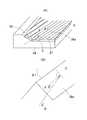
(第3の実施形態)
図13(A)は、本発明の実施形態3による面光源装置の一部を示す概略図である。この面光源装置では、傾斜面50を傾斜角の異なる複数段の平面(図13(A)では2段となっている。)で構成して傾斜面50の中段部が突出するようにしている。このような構造によれば、プリズムシート38aの端面の角が傾斜面50から浮いて傾斜面50に当たらないので、傾斜面50が平坦である場合のように、振動や衝撃でプリズムシート38aの角が傾斜面50に当たって傾斜面50に傷がつくことを防ぐことができる。その結果、傾斜面50の傷がついた箇所からの光の漏れを低減でき、面光源装置の発光品位を向上させることができる。(Third embodiment)
FIG. 13A is a schematic view showing a part of a surface light source device according to Embodiment 3 of the present invention. In this surface light source device, the
また、図13(B)は、実施形態3の変形例を示す。この変形例では、導光板34の下面と入光端面41に垂直な平面における傾斜面50の断面が円弧などの曲面状となるようにしたものである。このような変形例によれば、プリズムシート38aの下面が傾斜面50と滑らかに接触するので、より一層傾斜面50に傷がつきにくくなる。 FIG. 13B shows a modification of the third embodiment. In this modification, the cross section of the
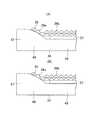
(第4の実施形態)
図14は、本発明の実施形態4の面光源装置に用いられる導光板34と光源35を示す概略図である。また、図15は、図14に示した導光板34の光導入部48を詳細に表した斜視図である。(Fourth embodiment)
FIG. 14 is a schematic view showing a
この実施形態においては、各光源35の前方に、表面が円錐状の傾斜面50となった光導入部48を設けている。さらに、各傾斜面50には、傾斜面50の傾斜方向に沿ったV溝71が放射状に形成されている。図示しないが、この実施形態でも、プリズムシート38aとプリズムシート38bのうち少なくとも一方のプリズムシートは、傾斜面50の上面に向けて延出され、傾斜面50の上方に重ねられる。 In this embodiment, a
この実施形態では、傾斜面50にV溝71(ラジアルプリズム)が形成されているので、傾斜面50に入射した光をV溝71で回帰反射させることによって傾斜面50からの光の漏れを少なくすることができる。また、傾斜面50にV溝71が形成されているので、傾斜面50の上へ延出されたプリズムシートと傾斜面50は線接触となって接触面積が小さくなる。この結果、傾斜面50からの漏れ光が少なくなって、発光領域の発光輝度が向上する。また、傾斜面50からの漏れ光が少なくなるので、ホットスポットや輝度むらも低減され発光品位の改善効果が高くなる。 In this embodiment, since the V-groove 71 (radial prism) is formed on the
(第5の実施形態)
図16は、本発明の実施形態5による面光源装置の概略図である。この面光源装置では、導光板本体49の上面に1枚のプリズムシート72を直接に重ね、その上に拡散板37を重ねている。プリズムシート72の下面には断面三角形状のプリズムが形成されており、プリズムシート72の端部は導光板本体49の上面から傾斜面50の上面へ向けて延びている。プリズムシート72としては、たとえば厚みが190μm、プリズムピッチが50μm、プリズム頂角が68°の三菱レイヨン製ダイヤアートM168YKを用いることができる。一方、拡散板37の端は、傾斜面50の下端から引っ込められている。(Fifth embodiment)
FIG. 16 is a schematic view of a surface light source device according to Embodiment 5 of the present invention. In this surface light source device, one
上面にプリズムを形成されたプリズムシートの場合には、プリズムを透過する光の屈折によって光を垂直方向へ偏向させる。これに対し、下面にプリズムを形成されたプリズムシートの場合には、プリズム内に入射した光をプリズム面で全反射させることによって光を垂直方向へ偏向させる。そのため、下面にプリズムを形成されたプリズムシート72は、光を垂直方向へ偏向させて集光させる効率が高い。一例では、下面にプリズムが形成されたものに比べて約1.5倍の光を垂直方向へ偏向させることができる。 In the case of a prism sheet having a prism formed on the upper surface, the light is deflected in the vertical direction by refraction of the light transmitted through the prism. On the other hand, in the case of a prism sheet having a prism formed on the lower surface, the light incident in the prism is totally reflected by the prism surface to deflect the light in the vertical direction. For this reason, the
したがって、下面プリズムのプリズムシート72を用いた場合には、傾斜面50から漏れた光は、プリズムシート72を透過することによってプリズムシート72に垂直な方向へ効率よく偏向され、遮光テープ39の下面に当たって吸収される。したがって、傾斜面50から漏れた光が遮光テープ39の窓55から漏れにくくなり、ホットスポットや輝度むらを軽減して発光品位を改善することができる。 Therefore, when the
また、発光領域から出射した光はプリズムシート72によって正面方向へ効率よく集光されるので、面光源装置の輝度が向上する。 In addition, since the light emitted from the light emitting region is efficiently condensed in the front direction by the
また、プリズムシート72は集光性が高いので、遮光テープ39の窓55の縁を傾斜面50に近づけることができる。 Further, since the
31 面光源装置
34 導光板
35 光源
36 フレキシブルプリント基板
37 拡散板
38a、38b プリズムシート
39 遮光テープ
41 入光端面
47 入光部
48 光導入部
49 導光板本体
50 傾斜面
55 窓
56 空気層
61、66 液晶表示装置
62、63 偏光板
64 液晶パネル
71 V溝
72 プリズムシートDESCRIPTION OF
Claims (10)
Translated fromJapanese前記入光端面と対向する位置に配置された光源、
前記導光板本体の発光側の面に置かれた拡散板及び1枚又は複数枚のプリズムシート、および、
前記導光板本体の発光領域を除く領域において前記拡散板及び前記プリズムシートよりも上方に配置された遮光シートを備え、
1枚又は複数枚の前記プリズムシートのうち少なくとも1枚のプリズムシートを前記光導入部の表面に向けて延出させたことを特徴とする面光源装置。A light incident end surface, a light guide plate main body that is thinner than the light incident end surface, and is formed so as to be continuous with the light guide plate main body, and gradually decreases in thickness from the light incident end surface side toward the light guide plate main body side. A light guide plate having a light introducing portion,
A light source disposed at a position facing the light incident end face;
A diffusion plate and one or more prism sheets placed on the light-emitting side surface of the light guide plate body, and
A light shielding sheet disposed above the diffuser plate and the prism sheet in a region excluding the light emitting region of the light guide plate body,
A surface light source device, wherein at least one of the one or a plurality of prism sheets is extended toward the surface of the light introducing portion.
2枚の前記プリズムシートのうち少なくとも一方のプリズムシートが前記光導入部の表面に向けて延出していることを特徴とする、請求項1に記載の面光源装置。The diffusion plate is placed on the light emitting side surface of the light guide plate body, and the two prism sheets each having a prism formed on the surface opposite to the surface facing the diffusion plate are superimposed on the diffusion plate. And
2. The surface light source device according to claim 1, wherein at least one of the two prism sheets extends toward a surface of the light introducing portion.
Priority Applications (5)
| Application Number | Priority Date | Filing Date | Title |
|---|---|---|---|
| JP2010148865AJP2012014909A (en) | 2010-06-30 | 2010-06-30 | Plane light source device |
| KR1020110059574AKR101309393B1 (en) | 2010-06-30 | 2011-06-20 | Surface light source apparatus |
| US13/172,002US8939633B2 (en) | 2010-06-30 | 2011-06-29 | Area light source device |
| TW100122752ATWI468800B (en) | 2010-06-30 | 2011-06-29 | Planar light source device |
| CN2011101906147ACN102313174A (en) | 2010-06-30 | 2011-06-29 | Area light source device |
Applications Claiming Priority (1)
| Application Number | Priority Date | Filing Date | Title |
|---|---|---|---|
| JP2010148865AJP2012014909A (en) | 2010-06-30 | 2010-06-30 | Plane light source device |
Publications (1)
| Publication Number | Publication Date |
|---|---|
| JP2012014909Atrue JP2012014909A (en) | 2012-01-19 |
Family
ID=45399614
Family Applications (1)
| Application Number | Title | Priority Date | Filing Date |
|---|---|---|---|
| JP2010148865APendingJP2012014909A (en) | 2010-06-30 | 2010-06-30 | Plane light source device |
Country Status (5)
| Country | Link |
|---|---|
| US (1) | US8939633B2 (en) |
| JP (1) | JP2012014909A (en) |
| KR (1) | KR101309393B1 (en) |
| CN (1) | CN102313174A (en) |
| TW (1) | TWI468800B (en) |
Cited By (7)
| Publication number | Priority date | Publication date | Assignee | Title |
|---|---|---|---|---|
| JP2014026920A (en)* | 2012-07-30 | 2014-02-06 | Minebea Co Ltd | Planar lighting device |
| WO2014041828A1 (en)* | 2012-09-13 | 2014-03-20 | 三菱電機株式会社 | Planar light source device and display device using same |
| JP2014096312A (en)* | 2012-11-12 | 2014-05-22 | Citizen Holdings Co Ltd | Planar light unit |
| US9086595B2 (en) | 2012-10-18 | 2015-07-21 | Omron Corporation | Surface light source device, liquid crystal display device, and mobile device |
| WO2016194716A1 (en)* | 2015-06-01 | 2016-12-08 | シャープ株式会社 | Edge-lit backlight device and liquid crystal display device |
| TWI625561B (en)* | 2017-04-07 | 2018-06-01 | 元太科技工業股份有限公司 | Light guide assembly |
| US10823895B2 (en) | 2014-01-29 | 2020-11-03 | E Ink Holdings Inc. | Light-emitting module |
Families Citing this family (40)
| Publication number | Priority date | Publication date | Assignee | Title |
|---|---|---|---|---|
| WO2012133160A1 (en)* | 2011-03-30 | 2012-10-04 | シャープ株式会社 | Illuminating device and display device provided with same |
| JP5278635B1 (en)* | 2012-03-09 | 2013-09-04 | オムロン株式会社 | Surface light source device |
| CN102645766A (en)* | 2012-04-28 | 2012-08-22 | 深圳市华星光电技术有限公司 | Liquid crystal display device and frame for same |
| KR101331908B1 (en)* | 2012-07-04 | 2013-11-22 | 엘지디스플레이 주식회사 | Backlight unit for liquid crystal display device and method of fabricating thereof |
| TWI479210B (en)* | 2013-01-08 | 2015-04-01 | Au Optronics Corp | Backlight module and light-guided plate |
| NL2010116C2 (en)* | 2013-01-11 | 2014-07-15 | Stichting Energie | Method of providing a boron doped region in a substrate and a solar cell using such a substrate. |
| US9223429B2 (en) | 2013-03-21 | 2015-12-29 | Htc Corporation | Touch module and electronic apparatus |
| KR20150000100A (en)* | 2013-06-24 | 2015-01-02 | 삼성디스플레이 주식회사 | Flat display device and manufacturing method thereof |
| TWI499845B (en)* | 2013-08-20 | 2015-09-11 | Au Optronics Corp | Thin type display module |
| WO2015064883A1 (en)* | 2013-11-01 | 2015-05-07 | Seoul Semiconductor Co., Ltd. | Light source module and backlight unit having the same |
| CN106062466B (en)* | 2013-11-15 | 2020-01-31 | 瑞尔D斯帕克有限责任公司 | Directional backlight with light emitting element package |
| JP5784769B2 (en)* | 2014-02-12 | 2015-09-24 | ミネベア株式会社 | Surface lighting device |
| CN104849793A (en) | 2014-02-19 | 2015-08-19 | 广州奥翼电子科技有限公司 | Electronic paper display light guide plate and electronic paper display |
| CN104061533B (en)* | 2014-06-13 | 2016-12-28 | 京东方科技集团股份有限公司 | Light conduction device, backlight module and display device |
| CN104076421A (en)* | 2014-06-20 | 2014-10-01 | 合肥京东方显示光源有限公司 | Black-rimmed prism sheet, prism sheet manufacturing method and equipment and display device |
| JP5959575B2 (en)* | 2014-06-30 | 2016-08-02 | ミネベア株式会社 | Planar illumination device and manufacturing method thereof |
| KR102177673B1 (en)* | 2014-07-18 | 2020-11-12 | 삼성디스플레이 주식회사 | Display device |
| US9851488B2 (en)* | 2014-08-18 | 2017-12-26 | New Optics, Ltd | Light guide plate and backlight unit including the same |
| CN104251423A (en)* | 2014-09-24 | 2014-12-31 | 京东方光科技有限公司 | Backlight module, display panel and display device |
| CN104391350B (en)* | 2014-11-26 | 2018-01-16 | 深圳市华星光电技术有限公司 | A kind of light guide plate and backlight module |
| CN106287321A (en)* | 2015-05-21 | 2017-01-04 | 鸿富锦精密工业(深圳)有限公司 | Light source and backlight module |
| CN110515150B (en)* | 2015-08-14 | 2021-06-01 | 瑞仪光电(苏州)有限公司 | Light guide film and backlight module |
| US10571618B2 (en)* | 2015-08-18 | 2020-02-25 | Apple Inc. | Display backlight with an optical film |
| TW201723544A (en)* | 2015-08-26 | 2017-07-01 | 3M新設資產公司 | Collimating step-wedge light guide |
| JP6440670B2 (en)* | 2015-12-24 | 2018-12-19 | ミネベアミツミ株式会社 | Surface lighting device |
| US10120119B2 (en)* | 2015-12-24 | 2018-11-06 | Minebea Mitsumi Inc. | Planar illumination apparatus with scattering unit by rayleigh scattering |
| CN105508936B (en) | 2016-01-26 | 2019-05-28 | 武汉华星光电技术有限公司 | Backlight module and display device |
| CN105629372A (en)* | 2016-03-31 | 2016-06-01 | 京东方科技集团股份有限公司 | Light guide plate and preparation method thereof |
| KR102560742B1 (en)* | 2016-04-14 | 2023-07-27 | 엘지디스플레이 주식회사 | Liquid Crystal Display device having two prism sheet |
| KR102595455B1 (en)* | 2016-12-20 | 2023-10-27 | 엘지디스플레이 주식회사 | Liquid crystal display device |
| JP6669691B2 (en)* | 2017-05-11 | 2020-03-18 | ミネベアミツミ株式会社 | Planar lighting device |
| TWI641975B (en)* | 2017-08-24 | 2018-11-21 | 友達光電股份有限公司 | Display panel |
| CN107728380B (en)* | 2017-11-20 | 2024-04-30 | 北京小米移动软件有限公司 | Backlight module and display device |
| CN108169843B (en)* | 2018-01-31 | 2021-03-19 | Oppo广东移动通信有限公司 | Electronic device and its display assembly, backlight module |
| CN108150896B (en)* | 2018-01-31 | 2021-01-15 | Oppo广东移动通信有限公司 | Electronic device and backlight module thereof |
| CN108279533B (en)* | 2018-02-13 | 2021-04-30 | 京东方科技集团股份有限公司 | Backlight module and display device |
| CN110109218A (en)* | 2019-05-30 | 2019-08-09 | 开平市盈光机电科技有限公司 | With the light guide plate of optical microstructures on a kind of lozenges |
| CN110161618A (en)* | 2019-05-30 | 2019-08-23 | 开平市盈光机电科技有限公司 | With the light guide plate of optical microstructures on a kind of incidence surface |
| CN110208898B (en)* | 2019-05-31 | 2020-11-20 | 内蒙古中森智能终端技术研发有限公司 | High-luminous-efficiency end face light guide plate for backlight module and preparation process thereof |
| CN115542611B (en) | 2022-11-25 | 2023-03-17 | 惠科股份有限公司 | Backlight module and display device |
Citations (6)
| Publication number | Priority date | Publication date | Assignee | Title |
|---|---|---|---|---|
| JP2003307731A (en)* | 2002-04-15 | 2003-10-31 | Seiko Epson Corp | Electro-optical devices and electronic equipment |
| JP2005183029A (en)* | 2003-12-16 | 2005-07-07 | Seiko Epson Corp | Lighting device |
| JP2006133274A (en)* | 2004-11-02 | 2006-05-25 | Sony Corp | Liquid crystal display device |
| JP2009080947A (en)* | 2007-09-25 | 2009-04-16 | Toshiba Matsushita Display Technology Co Ltd | Surface light source device and liquid crystal display device using the same |
| JP2010044994A (en)* | 2008-08-18 | 2010-02-25 | Omron Corp | Surface light source device |
| JP2010114073A (en)* | 2008-11-07 | 2010-05-20 | Samsung Electronics Co Ltd | Light guide plate, backlight assembly having the same, and display |
Family Cites Families (13)
| Publication number | Priority date | Publication date | Assignee | Title |
|---|---|---|---|---|
| JP2723414B2 (en) | 1992-01-27 | 1998-03-09 | 積水化学工業 株式会社 | Planar light emitting device |
| JP3992406B2 (en) | 1999-08-23 | 2007-10-17 | 株式会社エンプラス | Surface light source device, image display device including surface light source device, and reflecting member of surface light source device |
| KR100706752B1 (en)* | 2000-08-09 | 2007-04-11 | 삼성전자주식회사 | Reflective LCD |
| CN100401161C (en)* | 2003-05-21 | 2008-07-09 | 宇东科技股份有限公司 | Side light type backlight module and liquid crystal display |
| JP2006093104A (en)* | 2004-08-25 | 2006-04-06 | Seiko Instruments Inc | Lighting system, and display device using the same |
| JP4279761B2 (en) | 2004-09-27 | 2009-06-17 | 日本ライツ株式会社 | Flat illumination device and liquid crystal display device |
| JP2006236641A (en)* | 2005-02-23 | 2006-09-07 | Seiko Epson Corp | LIGHTING DEVICE, ELECTRO-OPTICAL DEVICE, AND ELECTRONIC DEVICE |
| TWI350360B (en) | 2007-06-12 | 2011-10-11 | Omron Tateisi Electronics Co | Surface light source device |
| JP4412425B2 (en)* | 2007-08-28 | 2010-02-10 | Dic株式会社 | Prism sheet, backlight unit using the same, and liquid crystal display device |
| JP5083111B2 (en)* | 2008-08-07 | 2012-11-28 | オムロン株式会社 | Surface light source device |
| TW201017229A (en)* | 2008-10-28 | 2010-05-01 | Optivision Technology Inc | Manufacturing method of light-converging plate for the prism pillar having inclined arrangement |
| JP2010113149A (en)* | 2008-11-06 | 2010-05-20 | Hitachi Displays Ltd | Liquid crystal display device |
| JP2010149944A (en)* | 2008-12-24 | 2010-07-08 | Hitachi Ltd | Elevator control device |
- 2010
- 2010-06-30JPJP2010148865Apatent/JP2012014909A/enactivePending
- 2011
- 2011-06-20KRKR1020110059574Apatent/KR101309393B1/ennot_activeExpired - Fee Related
- 2011-06-29CNCN2011101906147Apatent/CN102313174A/enactivePending
- 2011-06-29USUS13/172,002patent/US8939633B2/ennot_activeExpired - Fee Related
- 2011-06-29TWTW100122752Apatent/TWI468800B/ennot_activeIP Right Cessation
Patent Citations (6)
| Publication number | Priority date | Publication date | Assignee | Title |
|---|---|---|---|---|
| JP2003307731A (en)* | 2002-04-15 | 2003-10-31 | Seiko Epson Corp | Electro-optical devices and electronic equipment |
| JP2005183029A (en)* | 2003-12-16 | 2005-07-07 | Seiko Epson Corp | Lighting device |
| JP2006133274A (en)* | 2004-11-02 | 2006-05-25 | Sony Corp | Liquid crystal display device |
| JP2009080947A (en)* | 2007-09-25 | 2009-04-16 | Toshiba Matsushita Display Technology Co Ltd | Surface light source device and liquid crystal display device using the same |
| JP2010044994A (en)* | 2008-08-18 | 2010-02-25 | Omron Corp | Surface light source device |
| JP2010114073A (en)* | 2008-11-07 | 2010-05-20 | Samsung Electronics Co Ltd | Light guide plate, backlight assembly having the same, and display |
Cited By (8)
| Publication number | Priority date | Publication date | Assignee | Title |
|---|---|---|---|---|
| JP2014026920A (en)* | 2012-07-30 | 2014-02-06 | Minebea Co Ltd | Planar lighting device |
| WO2014041828A1 (en)* | 2012-09-13 | 2014-03-20 | 三菱電機株式会社 | Planar light source device and display device using same |
| US9500795B2 (en) | 2012-09-13 | 2016-11-22 | Mitsubishi Electric Corporation | Area light source device and display device using same |
| US9086595B2 (en) | 2012-10-18 | 2015-07-21 | Omron Corporation | Surface light source device, liquid crystal display device, and mobile device |
| JP2014096312A (en)* | 2012-11-12 | 2014-05-22 | Citizen Holdings Co Ltd | Planar light unit |
| US10823895B2 (en) | 2014-01-29 | 2020-11-03 | E Ink Holdings Inc. | Light-emitting module |
| WO2016194716A1 (en)* | 2015-06-01 | 2016-12-08 | シャープ株式会社 | Edge-lit backlight device and liquid crystal display device |
| TWI625561B (en)* | 2017-04-07 | 2018-06-01 | 元太科技工業股份有限公司 | Light guide assembly |
Also Published As
| Publication number | Publication date |
|---|---|
| TWI468800B (en) | 2015-01-11 |
| KR101309393B1 (en) | 2013-09-17 |
| US20120002437A1 (en) | 2012-01-05 |
| US8939633B2 (en) | 2015-01-27 |
| KR20120002437A (en) | 2012-01-05 |
| CN102313174A (en) | 2012-01-11 |
| TW201219922A (en) | 2012-05-16 |
Similar Documents
| Publication | Publication Date | Title |
|---|---|---|
| KR101309393B1 (en) | Surface light source apparatus | |
| US7484873B2 (en) | Illumination device having elliptical body and display device using the same | |
| KR100823802B1 (en) | Surface light source device and equipment using the device | |
| TWI431372B (en) | Surface light source device and liquid crystal display device | |
| JP4807205B2 (en) | Surface light source device | |
| KR101229874B1 (en) | Optic lens, optic package, backlight assembly and display device having the same | |
| KR101607287B1 (en) | Light guiding plate, backlight assembly and display apparatus having the same | |
| JP5295382B2 (en) | Planar light source device and display device using the same | |
| KR20190059337A (en) | Display Device | |
| EP2487515A2 (en) | Backlight assembly | |
| KR101463689B1 (en) | Spread Illuminating Apparatus | |
| KR102513442B1 (en) | Optical film and back light unit incuding the same | |
| JP2002245825A (en) | Backlight, liquid crystal display device and electronic equipment | |
| CN104180241A (en) | Backlight module | |
| JP2009140685A (en) | Backlight unit and liquid crystal display device | |
| US20070041215A1 (en) | Backlight module and light guide plate therein and method for diminishing corner shadow area | |
| KR20160095290A (en) | Liquid crystal display device | |
| JP2010287556A (en) | Lighting device and display including the same | |
| JP6682834B2 (en) | Light guide plate, surface light source device, display device, and electronic device | |
| WO2011099330A1 (en) | Backlight device, liquid crystal display device and television receiver | |
| JP7655810B2 (en) | Side edge type surface emitting device | |
| JP4530923B2 (en) | Light source and backlight | |
| US20250138368A1 (en) | Front light guide module, touch display device, and manufacturing method of touch display device | |
| KR20120085181A (en) | Light guide plate and surface light source device | |
| CN101988664A (en) | Side light type backlight module |
Legal Events
| Date | Code | Title | Description |
|---|---|---|---|
| A621 | Written request for application examination | Free format text:JAPANESE INTERMEDIATE CODE: A621 Effective date:20130111 | |
| A977 | Report on retrieval | Free format text:JAPANESE INTERMEDIATE CODE: A971007 Effective date:20131024 | |
| A131 | Notification of reasons for refusal | Free format text:JAPANESE INTERMEDIATE CODE: A131 Effective date:20131029 | |
| A02 | Decision of refusal | Free format text:JAPANESE INTERMEDIATE CODE: A02 Effective date:20140311 |