JP2012014894A - Illumination system and light emission module - Google Patents
Illumination system and light emission moduleDownload PDFInfo
- Publication number
- JP2012014894A JP2012014894AJP2010148572AJP2010148572AJP2012014894AJP 2012014894 AJP2012014894 AJP 2012014894AJP 2010148572 AJP2010148572 AJP 2010148572AJP 2010148572 AJP2010148572 AJP 2010148572AJP 2012014894 AJP2012014894 AJP 2012014894A
- Authority
- JP
- Japan
- Prior art keywords
- light emitting
- emitting module
- unit
- light
- illumination system
- Prior art date
- Legal status (The legal status is an assumption and is not a legal conclusion. Google has not performed a legal analysis and makes no representation as to the accuracy of the status listed.)
- Pending
Links
Images


Landscapes
- Led Device Packages (AREA)
- Led Devices (AREA)
- Circuit Arrangement For Electric Light Sources In General (AREA)
Abstract
Translated fromJapaneseDescription
Translated fromJapanese本発明は、発光素子を有した発光モジュールに関する。また本発明は、設置面に配設された複数の発光モジュールをそれぞれ制御して発光させる照明システムに関する。 The present invention relates to a light emitting module having a light emitting element. The present invention also relates to an illumination system that controls each of a plurality of light emitting modules disposed on an installation surface to emit light.
従来の照明システムは特許文献1に開示されている。この照明システムはパネル状の複数の発光モジュールをマトリクス状に配して屋内や屋外の壁面等の設置面に並設した発光ユニットを備えている。各発光モジュールには複数のLEDやOLED等の発光素子が設けられ、制御装置を介して電源に接続される。制御装置によって各発光モジュールが所定の駆動電流で駆動されて発光し、屋内や屋外の照明を行うことができる。また、制御装置によって各発光モジュールを独立に制御し、設置面上の異なる位置で所望の発光状態を得ることができる。 A conventional illumination system is disclosed in
しかしながら、上記従来の照明システムによると、発光モジュールに設けられるLED等の発光素子は発光時の明るさや色の光学特性にばらつきがある。このため、各発光モジュールに制御装置から同じ駆動電流(例えば、定格電流)を供給しても、各発光モジュールに設けられた発光素子の光学特性のばらつきによって各発光モジュールに明るさや色のばらつきが生じる。従って、発光ユニット全体が均一に発光しない。 However, according to the conventional illumination system, light emitting elements such as LEDs provided in the light emitting module have variations in brightness and color optical characteristics during light emission. For this reason, even if the same drive current (for example, rated current) is supplied from the control device to each light emitting module, variations in brightness and color occur in each light emitting module due to variations in the optical characteristics of the light emitting elements provided in each light emitting module. Arise. Therefore, the entire light emitting unit does not emit light uniformly.
また、発光ユニット内の各発光モジュールの配置に応じて異なる駆動電流を供給し、グラデーション等の照明効果を施して発光ユニットを発光させることができる。この場合においても、発光素子の光学特性のばらつきによって、例えば、明るい位置の発光モジュールが暗く発光する場合や暗い位置の発光モジュールが明るく発光する場合がある。 Also, different driving currents can be supplied according to the arrangement of the light emitting modules in the light emitting unit, and the light emitting unit can emit light by applying an illumination effect such as gradation. Even in this case, depending on the variation in the optical characteristics of the light emitting element, for example, the light emitting module in the bright position may emit light darkly, or the light emitting module in the dark position may emit light brightly.
従って、発光素子の光学特性のばらつきによって複数の発光モジュール間に明るさや色のばらつきが生じ、照明システムが所望の発光状態を得られない問題があった。 Accordingly, there is a problem in that the illumination system cannot obtain a desired light emission state due to variations in brightness and color among the plurality of light emitting modules due to variations in the optical characteristics of the light emitting elements.
本発明は、複数の発光モジュールによって所望の発光状態を得ることができる照明システムを提供することを目的とする。また本発明は、所望の発光状態を得ることができる発光モジュールを提供することを目的とする。 An object of this invention is to provide the illumination system which can obtain a desired light emission state with a some light emitting module. Another object of the present invention is to provide a light emitting module capable of obtaining a desired light emitting state.
上記目的を達成するために本発明は、一または複数の発光素子を有する発光モジュールを設置面に複数配設し、制御装置によって各前記発光モジュールの発光を制御する照明システムにおいて、前記発光モジュールは該発光モジュールの光学特性情報を保持する光学特性情報保持部を備え、前記制御装置は各前記発光モジュールの駆動電流を前記光学特性情報に基づいて可変することを特徴としている。 In order to achieve the above object, the present invention provides a lighting system in which a plurality of light emitting modules having one or a plurality of light emitting elements are arranged on an installation surface, and the light emission of each of the light emitting modules is controlled by a control device. An optical characteristic information holding unit for holding optical characteristic information of the light emitting module is provided, and the control device varies the drive current of each light emitting module based on the optical characteristic information.
この構成によると、複数の発光モジュールが屋内や屋外の壁面等の設置面に配設される。発光モジュールは光学特性情報保持部を備え、発光モジュール自身の明るさや色等の光学特性情報が光学特性情報保持部に保持される。各発光モジュールは制御装置により駆動電流が供給されて発光する。この時、制御装置は各発光モジュールの光学特性情報に基づいて各発光モジュールの駆動電流を所望の発光状態が得られるように可変する。 According to this configuration, the plurality of light emitting modules are arranged on an installation surface such as an indoor or outdoor wall surface. The light emitting module includes an optical characteristic information holding unit, and optical characteristic information such as brightness and color of the light emitting module itself is held in the optical characteristic information holding unit. Each light emitting module emits light when supplied with a drive current by a control device. At this time, the control device varies the drive current of each light emitting module based on the optical characteristic information of each light emitting module so that a desired light emitting state can be obtained.
また本発明は、上記構成の照明システムにおいて、前記制御装置は、各前記発光モジュールに対して所定の明るさまたは色が得られる駆動電流を前記光学特性情報から導出して各前記発光モジュールを駆動することを特徴としている。 According to the present invention, in the illumination system configured as described above, the control device drives each light emitting module by deriving a driving current that obtains a predetermined brightness or color for each light emitting module from the optical characteristic information. It is characterized by doing.
また本発明は、上記構成の照明システムにおいて、前記制御装置は、各前記発光モジュールが接続されるマスター部と、各前記発光モジュールに設けられるスレーブ部とを有し、前記マスター部から前記スレーブ部に各前記発光モジュールを発光させる明るさまたは色が指示され、前記スレーブ部によって前記マスター部の指示に対応した駆動電流を導出して前記発光モジュールを駆動することを特徴としている。 In the lighting system having the above-described configuration, the control device includes a master unit to which each light emitting module is connected and a slave unit provided in each light emitting module, and the master unit to the slave unit. The brightness or color for causing each light emitting module to emit light is instructed, and the light emitting module is driven by deriving a driving current corresponding to the instruction from the master unit by the slave unit.
この構成によると、各発光モジュールに接続されるマスター部は各発光モジュールの発光時の明るさまたは色の発光情報を送信する。発光情報は各発光モジュールに設けられるスレーブ部により受信される。スレーブ部は各発光モジュールの光学特性情報に基づいて発光情報の明るさまたは色が得られる駆動電流を導出し、発光素子に供給する。 According to this configuration, the master unit connected to each light emitting module transmits light emission information of brightness or color when each light emitting module emits light. The light emission information is received by a slave unit provided in each light emitting module. The slave unit derives a drive current for obtaining the brightness or color of the light emission information based on the optical characteristic information of each light emitting module, and supplies the drive current to the light emitting element.
また本発明は、上記構成の照明システムにおいて、各前記発光モジュールの位置情報を保持する位置情報保持部を備え、前記制御装置が前記位置情報に応じて各前記発光モジュールの駆動電流を可変することを特徴としている。この構成によると、各発光モジュールが設置面に設置されると、位置情報保持部に各発光モジュールの位置情報が保持される。制御装置は位置情報保持部から位置情報を取得し、発光モジュールの位置に応じて異なる発光状態で発光モジュールを発光させることができる。これにより、グラデーション等の照明効果等を得ることができる。 In the illumination system configured as described above, the present invention further includes a position information holding unit that holds position information of each light emitting module, and the control device varies a driving current of each light emitting module according to the position information. It is characterized by. According to this configuration, when each light emitting module is installed on the installation surface, position information of each light emitting module is held in the position information holding unit. The control device can acquire position information from the position information holding unit and cause the light emitting module to emit light in different light emission states depending on the position of the light emitting module. Thereby, illumination effects such as gradation can be obtained.
また本発明は、上記構成の照明システムにおいて、前記位置情報保持部が各前記発光モジュールに設けられたメモリから成ることを特徴としている。この構成によると、各発光モジュールが設置面に取付けられると、各発光モジュールに設けたメモリに位置情報が記憶される。 In the illumination system configured as described above, the present invention is characterized in that the position information holding unit includes a memory provided in each of the light emitting modules. According to this configuration, when each light emitting module is attached to the installation surface, position information is stored in a memory provided in each light emitting module.
また本発明は、上記構成の照明システムにおいて、前記位置情報保持部は、複数の前記発光モジュールを連結した発光ユニットの位置情報を記憶するメモリを有することを特徴としている。 According to the present invention, in the illumination system configured as described above, the position information holding unit includes a memory that stores position information of a light emitting unit in which a plurality of the light emitting modules are connected.
この構成によると、複数の発光モジュールを連結した発光ユニットが設置面に取付けられると、発光ユニットに設けたメモリに各発光ユニットの位置情報が記憶される。これにより、メモリに記憶された発光ユニットの位置情報を各発光モジュールの位置情報として制御装置によって各発光モジュールの駆動電流が可変される。 According to this configuration, when a light emitting unit in which a plurality of light emitting modules are connected is attached to the installation surface, position information of each light emitting unit is stored in a memory provided in the light emitting unit. Accordingly, the drive current of each light emitting module is varied by the control device using the position information of the light emitting unit stored in the memory as the position information of each light emitting module.
また本発明は、上記構成の照明システムにおいて、各前記発光モジュールに設けられるとともに前記発光ユニット上の各前記発光モジュールの位置を設定する設定部とを有することを特徴としている。 Further, the present invention is characterized in that the illumination system having the above-described configuration includes a setting unit that is provided in each light emitting module and sets a position of each light emitting module on the light emitting unit.
この構成によると、複数の発光モジュールを連結した発光ユニットが設置面に取付けられると、発光ユニットに設けたメモリに各発光ユニットの位置情報が記憶される。また、発光モジュールに設けたディップスイッチ等の設定部によって発光ユニット上の各発光モジュールの相対位置が設定される。メモリ及び設定部から成る位置情報保持部によって各発光モジュールの位置が保持される。 According to this configuration, when a light emitting unit in which a plurality of light emitting modules are connected is attached to the installation surface, position information of each light emitting unit is stored in a memory provided in the light emitting unit. The relative position of each light emitting module on the light emitting unit is set by a setting unit such as a dip switch provided on the light emitting module. The position of each light emitting module is held by a position information holding unit including a memory and a setting unit.
また本発明は、上記構成の照明システムにおいて、前記位置情報保持部が前記制御装置に設けられたメモリから成ることを特徴としている。この構成によると、各発光モジュールが設置面に取付けられると、制御装置に設けたメモリに各発光モジュールの位置情報が記憶される。 According to the present invention, in the illumination system configured as described above, the position information holding unit includes a memory provided in the control device. According to this configuration, when each light emitting module is attached to the installation surface, position information of each light emitting module is stored in a memory provided in the control device.
また本発明は、上記構成の照明システムにおいて、前記制御装置によって隣接する前記発光モジュールの輝度または色度の差を所定範囲にしたことを特徴としている。この構成によると、制御装置は位置情報保持部から読み出した位置情報によって隣接する発光モジュールを検知し、隣接する発光モジュールの輝度または色度の差が所定範囲になる駆動電流を各発光モジュールに供給する。 According to the present invention, in the illumination system configured as described above, a difference in luminance or chromaticity between adjacent light emitting modules is set to a predetermined range by the control device. According to this configuration, the control device detects adjacent light emitting modules based on the position information read from the position information holding unit, and supplies each light emitting module with a driving current in which the difference in luminance or chromaticity between adjacent light emitting modules is within a predetermined range. To do.
また本発明は、上記構成の照明システムにおいて、前記光学特性情報が前記発光モジュールに基準とする電流を供給した時の輝度情報から成ることを特徴としている。この構成によると、光学特性情報保持部に保持された輝度情報に基づいて制御装置は所望の明るさが得られる駆動電流を発光モジュールに供給する。 According to the present invention, in the illumination system configured as described above, the optical characteristic information includes luminance information when a reference current is supplied to the light emitting module. According to this configuration, based on the luminance information held in the optical characteristic information holding unit, the control device supplies a driving current that can obtain a desired brightness to the light emitting module.
また本発明は、上記構成の照明システムにおいて、前記発光素子が異なる色を発光する複数の発光部を有し、前記光学特性情報が前記発光モジュールに基準とする電流を供給した時の輝度情報及び色度情報から成ることを特徴としている。この構成によると、発光素子は例えば、RGBの各色を発光する複数の発光部を有する。光学特性情報保持部に保持された輝度情報及び色度情報に基づいて制御装置は所望の明るさ及び色が得られる駆動電流を発光モジュールに供給する。 According to the present invention, in the illumination system configured as described above, the light emitting element includes a plurality of light emitting units that emit different colors, and the optical characteristic information includes luminance information when a reference current is supplied to the light emitting module, and It is characterized by comprising chromaticity information. According to this configuration, the light emitting element has, for example, a plurality of light emitting units that emit RGB colors. Based on the luminance information and chromaticity information held in the optical characteristic information holding unit, the control device supplies the light emitting module with a driving current for obtaining desired brightness and color.
また本発明は、一または複数の発光素子を備えた発光モジュールにおいて、前記発光モジュールの光学特性情報を保持する光学特性情報保持部を設けたことを特徴としている。この構成によると、発光モジュールは発光モジュール自身の明るさや色等の光学特性情報をメモリ等の光学特性情報保持部に保持する。光学特性情報保持部から読み出される光学特性情報に基づいて可変した駆動電流が発光モジュールに供給される。 According to the present invention, in a light emitting module including one or more light emitting elements, an optical characteristic information holding unit that holds optical characteristic information of the light emitting module is provided. According to this configuration, the light emitting module holds optical characteristic information such as brightness and color of the light emitting module itself in the optical characteristic information holding unit such as a memory. A drive current that is variable based on the optical characteristic information read from the optical characteristic information holding unit is supplied to the light emitting module.
また本発明は、上記構成の発光モジュールにおいて、前記光学特性情報が基準とする電流を供給された時の輝度情報から成ることを特徴としている。 According to the present invention, in the light emitting module having the above-described configuration, the optical characteristic information includes luminance information when a current that is a reference is supplied.
また本発明は、上記構成の発光モジュールにおいて、前記発光素子が異なる色を発光する複数の発光部を有し、前記光学特性情報が基準とする電流を供給された時の輝度情報及び色度情報から成ることを特徴としている。 According to the present invention, in the light emitting module configured as described above, the light emitting element has a plurality of light emitting portions that emit different colors, and luminance information and chromaticity information when a current based on the optical characteristic information is supplied. It is characterized by comprising.
本発明の照明システムによると、発光モジュールが光学特性情報を保持する光学特性情報保持部を備え、制御装置が各発光モジュールの駆動電流を光学特性情報に基づいて可変するので、光学特性のばらつきを補正して各発光モジュールを発光させることができる。従って、照明システムの所望の発光状態を得ることができる。 According to the illumination system of the present invention, the light emitting module includes the optical characteristic information holding unit that holds the optical characteristic information, and the control device varies the drive current of each light emitting module based on the optical characteristic information. It can correct | amend and each light emitting module can be light-emitted. Therefore, a desired light emission state of the lighting system can be obtained.
また本発明の発光モジュールによると、発光モジュール自身の光学特性情報を保持する光学特性情報保持部を備えるので、光学特性のばらつきを補正して発光モジュールを所望の明るさや色で発光させることができる。 In addition, according to the light emitting module of the present invention, since the optical characteristic information holding unit for holding the optical characteristic information of the light emitting module itself is provided, the light emitting module can emit light with desired brightness and color by correcting the variation of the optical characteristics. .
以下に本発明の実施形態を図面を参照して説明する。図1は第1実施形態の照明システムの発光モジュールを示す平面図である。照明システム1(図3参照)は複数の発光モジュール11を連結した発光ユニット10(図2参照)を備えている。 Embodiments of the present invention will be described below with reference to the drawings. FIG. 1 is a plan view showing a light emitting module of the illumination system of the first embodiment. The illumination system 1 (see FIG. 3) includes a light emitting unit 10 (see FIG. 2) in which a plurality of
発光モジュール11は例えば、100mm×100mmの矩形に形成されたパネル状の基材12上に複数の発光素子13が設けられる。発光モジュール11内に設けられる発光素子13が一つであってもよい。発光素子13はLED等から成り、複数の発光部13R、13G、13Bを有している。発光部13R(赤色LED)、13G(緑色LED)、13B(青色LED)はそれぞれ赤色、緑色、青色を発光する。発光素子13は各発光部13R、13G、13Bの駆動電流に応じた明るさ及び色で発光する。尚、発光素子13が単色光を発光するLED等の素子であってもよい。 In the
発光素子13の前面にはレンズ14が配される。レンズ14によって発光素子13の出射光が平行光に変換される。基材12の各辺には接続端子15が設けられる。接続端子15によって隣接する発光モジュール11が電気的に接続される。また、基材12には詳細を後述するディップスイッチ16が設けられる。 A
図2は発光ユニット10を示す平面図である。発光ユニット10は枠材18によって複数の発光モジュール11をマトリクス状に連結し、例えば、600mm×1200mmに形成される。発光ユニット10には基準位置(同図では右下)の発光モジュール11の接続端子15から延びるコード部19が導出される。前述したように隣接する発光ユニット10は接続端子15により接続される。これにより、コード部19及び接続端子15を介して発光ユニット10内の各発光モジュール11に対して電力供給及びデータ通信が行われる。 FIG. 2 is a plan view showing the
また、発光モジュール11はディップスイッチ16(設定部:図1参照)によって発光ユニット10内の相対位置が設定される。ディップスイッチ16は例えば、2段に構成され、上段により列位置を設定して下段により行位置を設定する。 The
図3は照明システム1の構成を示すブロック図である。照明システム1は一または複数(本実施形態では3個)の発光ユニット10を制御する制御装置30を備えている。制御装置30には各発光ユニット10及び操作部31が接続される。制御装置30は商用電源に接続され、コード部19(図2参照)を介して接続される発光ユニット10の各発光モジュール11に駆動電流を供給する。操作部31は操作キーやダイヤルキーを有したリモートコントローラ等から成り、照明システム1のオンオフ操作や照明効果の設定操作等を行う。 FIG. 3 is a block diagram showing the configuration of the
発光ユニット10は屋内や屋外の壁面等の設置面に設置され、制御装置30から供給される駆動電流によって各発光モジュール11が発光して屋内や屋外を照明する。複数の発光モジュール11を有する発光ユニット10にはユニット位置記憶部21が設けられる。ユニット位置記憶部21は不揮発性のメモリにより形成され、基準位置(例えば、制御装置30)に対する発光ユニット10の位置情報が記憶される。 The
これにより、各発光モジュール11はユニット位置記憶部21及びディップスイッチ16に保持される位置情報によって基準位置に対する位置が特定される。従って、ユニット位置記憶部21及びディップスイッチ16は各発光モジュール11の位置情報を保持する位置情報保持部を構成する。尚、ユニット位置記憶部21及びディップスイッチ16に保持される位置情報はコード部19(図2参照)を介して制御装置30によって読み出すことができる。また、位置情報保持部がユニット位置記憶部21を省いてディップスイッチ16のみから構成されていてもよい。 Thereby, the position of each light emitting
各発光モジュール11には光学特性記憶部17(光学特性情報保持部)が設けられる。光学特性記憶部17は不揮発性のメモリにより形成され、発光モジュール11自身の光学特性情報を記憶して保持する。発光モジュール11の光学特性情報は複数の発光素子13の光学特性情報の平均値から成っている。 Each
光学特性情報は発光モジュール11を基準とする電流としての定格電流で駆動した時のRGB形式やYxy形式等の輝度情報及び色度情報を有する。尚、発光素子13が単色光を発光する場合は光学特性情報が輝度情報を有し、色度情報を含まなくてもよい。 The optical characteristic information includes luminance information and chromaticity information in the RGB format, the Yxy format, and the like when the
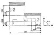
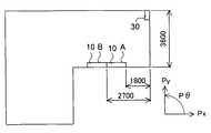
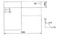
図4、図5は照明システム1の施工例の家屋を示す正面図及び側面図である。また、図6、図7はこの家屋の1階の平面図及び2階の平面図を示している。これらの図中の数値の単位はmmである。照明システム1は1階の壁面に2つの発光ユニット10(以下、「発光ユニットA」、「発光ユニットB」という場合がある)が設置され、2階の壁面に1つの発光ユニット10(以下、「発光ユニットC」という場合がある)が設置される。尚、正面から見て1階の右奥に制御装置30が設置される。 4 and 5 are a front view and a side view showing a house of an example of construction of the
表1は光学特性記憶部17及びユニット位置記憶部21により記憶されるデータの一例を示している。 Table 1 shows an example of data stored in the optical

光学特性記憶部17には発光モジュール11のID及び光学特性情報が記憶される。IDが「AA」、「AB」、「AC」は発光ユニットAの発光モジュール11を示している。IDが「BA」、「BB」、「BC」は発光ユニットBの発光モジュール11を示している。IDが「CA」、「CB」、「CC」は発光ユニットCの発光モジュール11を示している。理解を容易にするために上記のIDを例にしているが、各発光モジュール11は発光ユニット10を形成する前に製造番号等の固有のIDが付される。このため、通常は発光ユニット10内で各発光モジュール11のIDが不規則な値になる。 The optical
光学特性情報は基準とする電流である定格電流時のスペック(Yxy形式)及びスペックからの差分値(ΔY、Δx、Δy)等により表わされる。尚、光学特性情報(Y、x、y、ΔY、Δx、Δy)は光学素子13のRGB値から計算されるYxy値に所定の演算処理を施した値になっている。光学特性情報として定格電流時の絶対値(スペック+差分値)を記憶してもよい。 The optical characteristic information is represented by a specification (Yxy format) at the rated current, which is a reference current, and a difference value (ΔY, Δx, Δy) from the specification. The optical characteristic information (Y, x, y, ΔY, Δx, Δy) is a value obtained by performing predetermined arithmetic processing on the Yxy value calculated from the RGB values of the
ユニット位置記憶部21には制御装置30の設置位置に対する発光ユニット10の位置情報が記憶される。位置情報には発光ユニット10の座標及び向きが含まれる。この時、制御装置30の設置位置に対して左右方向をPx方向(右方向を正方向)、前後方向をPy方向(後方向を正方向)、上下方向をPz方向(上方向を正方向)としている。また、発光ユニット10の向きは出射方向のPx方向に対するPx−Py面内の角度Pθ及び鉛直に対する角度Pφで表わしている。例えば、発光ユニット10を天井面に設置した場合はPφ=90゜、床面に設置した場合はPφ=270゜である。 The unit
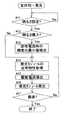
上記構成の照明システム1において、図8は発光ユニットA、B、C全体を均一に発光させる全体均一発光モードの動作を示すフローチャートである。説明を簡単にするため、照明光の明るさを可変する動作を説明するが、同様の動作によって照明光の明るさ及び色を可変することができる。 In the
ステップ#11では操作部31の操作によって照明の明るさが設定されるまで待機する。照明の明るさはボリューム等によって例えば、5段階のレベルに切り替えることができるようになっている。照明の明るさが設定されるとステップ#12で最大レベルの明るさか否かが判断される。設定された明るさが最大レベルでない場合はステップ#14に移行する。 In
設定された明るさが最大レベルの場合は各発光モジュール11に定格電流を加えてスペックの輝度で照明を行えばよい。しかし、定格電流時にスペックと異なる輝度の発光モジュール11が含まれる。このため、ステップ#13で全ての発光ユニット10の発光モジュール11の光学特性記憶部17から定格電流時の輝度の差分値ΔYが読み出され、輝度の最小値が検出される。例えば、前述の表1では、IDが「BA」の発光モジュール11の輝度の差分値ΔYが−100で最小値になっており、差分値ΔY=−100(輝度Y+ΔY=2900)が取得される。 If the set brightness is at the maximum level, the rated current may be applied to each light emitting
ステップ#14では一の発光モジュール11の光学特性記憶部17から定格電流時の輝度が読み出される。ステップ#15では設定された明るさに対応する輝度を得る駆動電流が制御装置30の演算によって導出される。 In
例えば、明るさが50%に設定されている場合は、輝度がスペックの50%(Y=1500)となる駆動電流が導出される。即ち、輝度(Y+ΔY)が3000の発光モジュール11の駆動電流は定格電流の50%である。輝度(Y+ΔY)が3300の発光モジュール11の駆動電流は定格電流の50%×f(3000/3300)である。輝度(Y+ΔY)が2900の発光モジュール11の駆動電流は定格電流の50%×f(3000/2900)である。ここで、fは、発光素子の駆動電流−発光輝度特性によって決定される所定の係数である。 For example, when the brightness is set to 50%, a drive current with a luminance of 50% of the specification (Y = 1500) is derived. That is, the drive current of the
この時、明るさが100%(最大レベル)に設定されている場合は、ステップ#13で検出した輝度の最小値となる駆動電流が制御装置30によって導出される。即ち、表1の例では輝度(Y+ΔY)が3000の発光モジュール11の駆動電流は定格電流×f(2900/3000)である。輝度(Y+ΔY)が3300の発光モジュール11の駆動電流は定格電流×f(2900/3300)である。輝度(Y+ΔY)が2900の発光モジュール11の駆動電流は定格電流×fである。これにより、定格電流を超える駆動電流の供給が防止される。 At this time, if the brightness is set to 100% (maximum level), the
ステップ#16ではステップ#15で導出した駆動電流が該発光モジュール11に供給され、発光モジュール11が発光する。ステップ#17では各発光ユニットA、B、Cの全ての発光モジュール11を発光して最後の発光モジュール11になったか否かが判断される。最後の発光モジュール11でない場合はステップ#14に戻り、ステップ#14〜#17が繰り返し行われる。そして、最後の発光モジュール11を発光させると、処理を終了する。これにより、各発光モジュール11に光学特性のばらつきを補正した駆動電流を供給し、各発光モジュール11を均一な輝度で発光させることができる。 In
尚、全体均一発光モードでは発光モジュール11の位置に拘わらず、均一な輝度で発光させる。このため、ユニット位置記憶部21及びディップスイッチ16から成る位置情報保持部を省いた照明システム1であってもよい。 In the whole uniform light emission mode, light is emitted with uniform brightness regardless of the position of the
次に、図9は各発光モジュール11の配置に応じて徐々に明るさを可変するグラデーション発光モードの動作を示すフローチャートである。操作部31の操作によってグラデーション発光モードが選択されると、ステップ#21で制御装置30によって発光ユニット10の設置面上の位置別の輝度が設定される。 Next, FIG. 9 is a flowchart showing the operation of the gradation light emission mode in which the brightness is gradually changed according to the arrangement of the
例えば、上方の発光モジュール11の輝度が高く設定され、下方の発光モジュール11の輝度が低く設定される。この時、輝度の最大値をスペックに対して100%に設定すると、定格電流時にスペックの輝度が得られない発光モジュール11がある。このため、輝度の最大値はスペックの90%程度に設定される。また、発光ユニットA、B、Cに応じて異なるグラデーション効果を操作部31により設定できるようにしてもよい。 For example, the luminance of the upper
ステップ#22では一の発光モジュール11の光学特性記憶部17から定格電流時の輝度(Y+ΔY)が読み出される。ステップ#23では該発光モジュール11の位置情報がユニット位置記憶部21及びディップスイッチ16から取得される。ステップ#24では発光モジュール11の位置に応じた輝度を得る駆動電流が制御装置30の演算によって導出される。 In
例えば、輝度が90%に設定された位置の発光モジュール11に対して、輝度がスペックの90%(Y=2700)となる駆動電流が光学特性に基づいて導出される。輝度が50%に設定された位置の発光モジュール11に対して、輝度がスペックの50%(Y=1500)となる駆動電流が光学特性に基づいて導出される。 For example, with respect to the
ステップ#25ではステップ#24で導出した駆動電流が該発光モジュール11に供給され、発光モジュール11が発光する。ステップ#26では各発光ユニットA、B、Cの全ての発光モジュール11が発光して最後の発光モジュール11になったか否かが判断される。最後の発光モジュール11でない場合はステップ#22に戻り、ステップ#22〜#26が繰り返し行われる。そして、最後の発光モジュール11を発光させると、処理を終了する。これにより、各発光モジュール11に光学特性のばらつきを補正した駆動電流を供給してグラデーション発光を行うことができる。 In
尚、発光モジュール11を位置に応じて異なる輝度で発光し、グラデーション以外の照明効果を施してもよい。また、発光モジュール11を位置に応じて異なる輝度及び色で発光させた照明効果を施してもよい。 Note that the
次に、図10は部分均一発光モードの動作を示すフローチャートである。発光ユニットA、B、C全体を同じ明るさで発光する際に、人の目には隣接する発光モジュール11の明るさの差を容易に判別できるが、離れた発光モジュール11の明るさの差を判別しにくくなる。このため、部分均一発光モードでは隣接する発光モジュール11間の輝度の差を所定範囲内になるように可変し、離れた発光モジュール11の輝度の差が大きくても制御を施さないようにしている。これにより、制御装置30の負荷を軽減することができる。 Next, FIG. 10 is a flowchart showing the operation in the partial uniform light emission mode. When the entire light-emitting units A, B, and C emit light with the same brightness, the difference in brightness between the adjacent light-emitting
ステップ#31では操作部31の操作によって照明の明るさが設定されるまで待機する。照明の明るさが設定されるとステップ#32で一の発光モジュール11の光学特性記憶部17から定格電流時の輝度(Y、ΔY)が読み出される。ステップ#33ではユニット位置記憶部21及びディップスイッチ16から発光モジュール11の位置情報が取得される。 In
ステップ#34では隣接する発光モジュール11との輝度の差が所定値以内か否かが判断される。隣接する発光モジュール11との輝度の差が所定値以内の場合、及び最初の発光モジュール11の場合はステップ#37に移行する。ステップ#37ではステップ#31で設定した明るさに対応する駆動電流で発光モジュール11が発光する。例えば、明るさが100%の場合は定格電流の駆動電流が発光モジュール11に供給され、明るさが50%の場合は定格電流の50%の駆動電流が発光モジュール11に供給される。 In
隣接する発光モジュール11との輝度の差が所定値よりも大きい場合は、ステップ#35で隣接する発光モジュール11の輝度に合わせた駆動電流が導出される。例えば、明るさの設定を100%とし、輝度Yの差が100を超える時にステップ#35に移行する。カレントの発光モジュール11の輝度(Y+ΔY)が3300、隣接する発光モジュール11の輝度(Y+ΔY)が2900とすると、カレントの発光モジュール11に対して例えば、スペック(Y=3000)の輝度に対応する駆動電流が導出される。この時、カレントの発光モジュール11は定格電流よりも低い駆動電流が供給され、スペックの輝度になる。 When the difference in luminance between the adjacent
また、カレントの発光モジュール11の輝度Yが3000、隣接する発光モジュール11の輝度Yが3300の時に、隣接する発光モジュール11に対して例えば、スペック(Y=3000)の輝度に対応する駆動電流が導出される。これにより、カレントの発光モジュール11の駆動電流が定格電流を超えることが防止される。この時、既に発光された隣接する発光モジュール11の駆動電流が変更される。 When the luminance Y of the current
このため、ステップ#36では隣接する発光モジュール11の駆動電流が変更されたか否かが判断される。隣接する発光モジュール11の駆動電流が変更されていない場合はステップ#37に移行する。隣接する発光モジュール11の駆動電流が変更された場合は、ステップ#34に戻り、隣接する発光モジュール11に対して更に隣接する発光モジュール11と間の輝度の差が比較される。そして、ステップ#34〜#36が繰り返し行われる。 Therefore, in
ステップ#37ではステップ#35で導出した駆動電流が該発光モジュール11に供給され、発光モジュール11が発光する。ステップ#38では各発光ユニットA、B、Cの全ての発光モジュール11が発光して最後の発光モジュール11になったか否かが判断される。最後の発光モジュール11でない場合はステップ#32に戻り、ステップ#32〜#38が繰り返し行われる。そして、最後の発光モジュール11を発光させると、処理を終了する。これにより、隣接する発光モジュール11を所定の輝度の差で発光させることができる。 In
尚、同様の動作によって隣接する発光モジュール11の輝度(Y)及び色度(x、y)の差を所定範囲内になるように駆動電流を可変してもよい。 The drive current may be varied so that the difference between the luminance (Y) and chromaticity (x, y) of adjacent
本実施形態の照明システム1によると、発光モジュール11が光学特性情報を保持する光学特性記憶部17(光学特性情報保持部)を備え、制御装置30が各発光モジュール11の駆動電流を光学特性情報に基づいて可変するので、光学特性のばらつきを補正して各発光モジュール11を発光させることができる。従って、照明システム1を均一に発光させる場合やグラデーション等の照明効果を施して発光させる場合等に所望の明るさや色の発光状態を得ることができる。 According to the
また、各発光モジュール11に対して所定の明るさまたは色が得られる駆動電流を制御装置30によって光学特性情報から導出して各発光モジュール11を駆動するので、各発光モジュール11を容易に所望の発光状態で発光させることができる。 In addition, since the driving current for obtaining a predetermined brightness or color for each light emitting
また、ユニット位置記憶部21及びディップスイッチ16が各発光モジュール11の位置情報を保持する位置情報保持部を構成し、制御装置30が位置情報に応じて各発光モジュール11の駆動電流を可変するので、複数の発光モジュール11に対してグラデーション等の照明効果を施すことや隣接する発光モジュール11を均一に発光させることができる。 The unit
尚、各発光モジュール11が単に電気的に接続されているだけで、位置情報保持部がディップスイッチ16を省いてユニット位置記憶部21のみから構成される場合であってもよい。この場合は、ユニット位置記憶部21に記憶された位置情報を各発光モジュール11の位置情報として制御装置30が各発光モジュール11の駆動電流を可変する。 Note that the
これにより、発光ユニット10を構成する発光モジュール11の個数が例えば4個等の少ない場合に、同じ位置情報を有した発光モジュール11を同じ明るさや色で発光させる。そして、位置情報に基づいて複数の発光ユニット10に対してグラデーション等の照明効果を施すことや隣接する発光ユニット10を均一に発光させることができる。従って、より簡易な構成で照明効果等を得ることができる。 Accordingly, when the number of
また、複数の発光モジュール11を連結した発光ユニット10の位置情報を記憶したメモリから成るユニット位置記憶部21と、各発光モジュール11に設けられて発光ユニット10上の各発光モジュール11の位置を設定するディップスイッチ16(設定部)とを有するので、各発光モジュール11の位置を容易に保持することができる。 In addition, a unit
また、部分均一発光モードにおいて制御装置30によって隣接する発光モジュール10の輝度または色度の差を所定範囲にしたので、一部の発光モジュール10のみに対して光学特性情報に応じて駆動電流を可変すればよい。従って、制御装置30の負担を軽減することができる。 Further, in the partial uniform light emission mode, the difference in luminance or chromaticity of the adjacent
また、発光素子13が異なる色を発光する複数の発光部13R、13G、13Bを有し、光学特性情報が発光モジュール10の定格電流時の輝度情報及び色度情報から成るので、発光モジュール10を所望の明るさ及び色で発光させることができる。 In addition, since the
尚、発光素子13が単色光を発光する場合は光学特性記憶部17で記憶される光学特性情報を発光モジュール10の定格電流時の輝度情報とし、発光モジュール10を所望の明るさで発光させることができる。 When the
次に、図11は第2実施形態の照明システムの構成を示すブロック図である。説明の便宜上、前述の図1〜図10に示す第1実施形態と同一の部分は同一の符号を付している。本実施形態は第1実施形態に対してユニット位置記憶部21及びディップスイッチ16(いずれも図3参照)が省かれ、モジュール位置記憶部20が設けられる。その他の部分は第1実施形態と同様である。 Next, FIG. 11 is a block diagram showing the configuration of the illumination system of the second embodiment. For convenience of explanation, the same parts as those in the first embodiment shown in FIGS. In the present embodiment, the unit
モジュール位置記憶部20は各発光モジュール10に設けられ、不揮発性のメモリにより形成される。モジュール位置記憶部20には基準位置(例えば、制御装置30)に対する発光モジュール11の位置の位置情報が施工時の入力等によって記憶される。即ち、モジュール位置記憶部20は発光モジュール10の位置情報を保持する位置情報保持部を構成する。 The module
モジュール位置記憶部20によって各発光モジュール11の位置が特定され、位置に応じた駆動電流が供給される。従って、第1実施形態と同様に、グラデーション発光モード等の照明効果を施した動作や部分均一発光モードの動作を行うことができる。 The position of each light emitting
次に、図12は第3実施形態の照明システムの構成を示すブロック図である。説明の便宜上、前述の図11に示す第2実施形態と同一の部分は同一の符号を付している。本実施形態は第2実施形態に対して制御装置30がマスター部30aとスレーブ部30bとに分離して構成される。その他の部分は第2実施形態と同様である。 Next, FIG. 12 is a block diagram showing the configuration of the illumination system of the third embodiment. For convenience of explanation, the same parts as those in the second embodiment shown in FIG. 11 are given the same reference numerals. In the present embodiment, the
マスター部30aは商用電源に接続され、コード部19(図2参照)を介して各発光ユニット10に接続される。スレーブ部30bは各発光モジュール11に設けられてマスター部30aと通信を行う。また、マスター部30aからスレーブ部30bに各発光モジュール11を発光させる明るさまたは色の発光情報が指示される。そして、スレーブ部30bによってマスター部30aから指示された明るさまたは色の発光情報に対応した駆動電流を導出して発光モジュール10を駆動する。 The
本実施形態によっても第2実施形態と同様の動作を行い、同様の効果を得ることができる。尚、第1実施形態の制御装置30をマスター部30aとスレーブ部30bとに分離して構成してもよい。 Also in this embodiment, the same operation as that of the second embodiment can be performed, and the same effect can be obtained. In addition, you may comprise the
第1〜第3実施形態において、照明システム1は複数の発光ユニット10を備えているが、複数の発光モジュール11を有する発光ユニット10が一つであってもよい。また、一の発光モジュール11を有する発光ユニット10を複数設けてもよい。 In the first to third embodiments, the
また、照明システム1は矩形のパネル状の発光モジュール11を備えているが、発光モジュール11は矩形に限らず円形や多角形の形状でもよい。また、発光モジュール11をパネル状ではなくブロック状に形成してもよい。 Moreover, although the
また、発光モジュール11の位置情報を発光ユニット10または発光モジュール11によって保持しているが、制御装置30に設けた不揮発性のメモリに各発光モジュール11の位置情報を記憶してもよい。 Further, although the position information of the
本発明によると、設置面に配設された複数の発光モジュールをそれぞれ制御して発光させる照明システムに利用することができる。 ADVANTAGE OF THE INVENTION According to this invention, it can utilize for the illumination system which controls each of the several light emission module arrange | positioned on the installation surface, and makes it light-emit.
1 照明システム
10 発光ユニット
11 発光モジュール
12 基材
13 発光素子
14 レンズ
15 接続端子
16 ディップスイッチ
17 光学特性記憶部
18 枠材
19 コード部
20 モジュール位置記憶部
21 ユニット位置記憶部
30 制御装置
31 操作部DESCRIPTION OF
Claims (14)
Translated fromJapanesePriority Applications (1)
| Application Number | Priority Date | Filing Date | Title |
|---|---|---|---|
| JP2010148572AJP2012014894A (en) | 2010-06-30 | 2010-06-30 | Illumination system and light emission module |
Applications Claiming Priority (1)
| Application Number | Priority Date | Filing Date | Title |
|---|---|---|---|
| JP2010148572AJP2012014894A (en) | 2010-06-30 | 2010-06-30 | Illumination system and light emission module |
Publications (1)
| Publication Number | Publication Date |
|---|---|
| JP2012014894Atrue JP2012014894A (en) | 2012-01-19 |
Family
ID=45601099
Family Applications (1)
| Application Number | Title | Priority Date | Filing Date |
|---|---|---|---|
| JP2010148572APendingJP2012014894A (en) | 2010-06-30 | 2010-06-30 | Illumination system and light emission module |
Country Status (1)
| Country | Link |
|---|---|
| JP (1) | JP2012014894A (en) |
Cited By (1)
| Publication number | Priority date | Publication date | Assignee | Title |
|---|---|---|---|---|
| JP2021034162A (en)* | 2019-08-20 | 2021-03-01 | パナソニックIpマネジメント株式会社 | Lighting system, control unit, light source unit, and computer program |
Citations (4)
| Publication number | Priority date | Publication date | Assignee | Title |
|---|---|---|---|---|
| JPH06314596A (en)* | 1993-04-30 | 1994-11-08 | Toshiba Lighting & Technol Corp | Lighting control system |
| JP2004265635A (en)* | 2003-02-24 | 2004-09-24 | Sony Corp | Backlight, backlight drive, display |
| JP2006185765A (en)* | 2004-12-28 | 2006-07-13 | Yoshiro Mizuno | Lighting system, lighting system and display system consisting of units with self-sustaining control function |
| JP2008108589A (en)* | 2006-10-26 | 2008-05-08 | Led Technology:Kk | Light emitting unit |
- 2010
- 2010-06-30JPJP2010148572Apatent/JP2012014894A/enactivePending
Patent Citations (4)
| Publication number | Priority date | Publication date | Assignee | Title |
|---|---|---|---|---|
| JPH06314596A (en)* | 1993-04-30 | 1994-11-08 | Toshiba Lighting & Technol Corp | Lighting control system |
| JP2004265635A (en)* | 2003-02-24 | 2004-09-24 | Sony Corp | Backlight, backlight drive, display |
| JP2006185765A (en)* | 2004-12-28 | 2006-07-13 | Yoshiro Mizuno | Lighting system, lighting system and display system consisting of units with self-sustaining control function |
| JP2008108589A (en)* | 2006-10-26 | 2008-05-08 | Led Technology:Kk | Light emitting unit |
Cited By (2)
| Publication number | Priority date | Publication date | Assignee | Title |
|---|---|---|---|---|
| JP2021034162A (en)* | 2019-08-20 | 2021-03-01 | パナソニックIpマネジメント株式会社 | Lighting system, control unit, light source unit, and computer program |
| JP7378043B2 (en) | 2019-08-20 | 2023-11-13 | パナソニックIpマネジメント株式会社 | Lighting systems and controls |
Similar Documents
| Publication | Publication Date | Title |
|---|---|---|
| US8384294B2 (en) | System and method for color creation and matching | |
| US20140240964A1 (en) | Illuminated makeup mirror set | |
| US8610374B2 (en) | Lamp unit with a plurality of light source and toggle remote control method for selecting a drive setting therefor | |
| US20140132180A1 (en) | Lighting Control Device, Lighting Control System and Program Product | |
| JPWO2013061749A1 (en) | Lighting apparatus and lighting apparatus using the same | |
| JPWO2017029895A1 (en) | LED display device and driving device | |
| US9295122B2 (en) | Light source control device and game machine | |
| JP4575894B2 (en) | Lighting equipment | |
| JP2012014894A (en) | Illumination system and light emission module | |
| CN207926973U (en) | An intelligent lighting system | |
| US10276106B2 (en) | Power supply and display device | |
| JP2013073837A (en) | Lighting device | |
| TWI517754B (en) | Light source module and light-emitting control method | |
| CN212430675U (en) | Material indicating device | |
| JP2009170249A (en) | lighting equipment | |
| US20210350743A1 (en) | Method of using a dynamic light field system | |
| JP5005189B2 (en) | Display system | |
| JP2003076335A (en) | LED display device and control method of LED display device using the same | |
| WO2013128565A1 (en) | Illumination correction device | |
| CN216849269U (en) | Light emitting device for display | |
| KR101243693B1 (en) | Portable LED Lighting Device | |
| JP2008192842A (en) | Lighting system | |
| JP6915456B2 (en) | Lighting control device, lighting control method and lighting control program | |
| JP7154004B2 (en) | LIGHTING CONTROL DEVICE, LIGHTING CONTROL METHOD AND LIGHTING CONTROL PROGRAM | |
| WO2025187714A1 (en) | Illumination control device, illumination device, illumination control method, and program |
Legal Events
| Date | Code | Title | Description |
|---|---|---|---|
| A621 | Written request for application examination | Free format text:JAPANESE INTERMEDIATE CODE: A621 Effective date:20130401 | |
| A977 | Report on retrieval | Free format text:JAPANESE INTERMEDIATE CODE: A971007 Effective date:20140116 | |
| A131 | Notification of reasons for refusal | Free format text:JAPANESE INTERMEDIATE CODE: A131 Effective date:20140128 | |
| A521 | Request for written amendment filed | Free format text:JAPANESE INTERMEDIATE CODE: A523 Effective date:20140328 | |
| A02 | Decision of refusal | Free format text:JAPANESE INTERMEDIATE CODE: A02 Effective date:20140603 |