JP2012013980A - Stereoscopic display device and display drive circuit - Google Patents
Stereoscopic display device and display drive circuitDownload PDFInfo
- Publication number
- JP2012013980A JP2012013980AJP2010150912AJP2010150912AJP2012013980AJP 2012013980 AJP2012013980 AJP 2012013980AJP 2010150912 AJP2010150912 AJP 2010150912AJP 2010150912 AJP2010150912 AJP 2010150912AJP 2012013980 AJP2012013980 AJP 2012013980A
- Authority
- JP
- Japan
- Prior art keywords
- unit
- light
- opening
- backlight
- barrier
- Prior art date
- Legal status (The legal status is an assumption and is not a legal conclusion. Google has not performed a legal analysis and makes no representation as to the accuracy of the status listed.)
- Pending
Links
Images


Classifications
- H—ELECTRICITY
- H04—ELECTRIC COMMUNICATION TECHNIQUE
- H04N—PICTORIAL COMMUNICATION, e.g. TELEVISION
- H04N13/00—Stereoscopic video systems; Multi-view video systems; Details thereof
- H04N13/30—Image reproducers
- H04N13/302—Image reproducers for viewing without the aid of special glasses, i.e. using autostereoscopic displays
- H04N13/31—Image reproducers for viewing without the aid of special glasses, i.e. using autostereoscopic displays using parallax barriers
- H04N13/315—Image reproducers for viewing without the aid of special glasses, i.e. using autostereoscopic displays using parallax barriers the parallax barriers being time-variant
- G—PHYSICS
- G02—OPTICS
- G02B—OPTICAL ELEMENTS, SYSTEMS OR APPARATUS
- G02B30/00—Optical systems or apparatus for producing three-dimensional [3D] effects, e.g. stereoscopic images
- G—PHYSICS
- G09—EDUCATION; CRYPTOGRAPHY; DISPLAY; ADVERTISING; SEALS
- G09G—ARRANGEMENTS OR CIRCUITS FOR CONTROL OF INDICATING DEVICES USING STATIC MEANS TO PRESENT VARIABLE INFORMATION
- G09G3/00—Control arrangements or circuits, of interest only in connection with visual indicators other than cathode-ray tubes
- G09G3/20—Control arrangements or circuits, of interest only in connection with visual indicators other than cathode-ray tubes for presentation of an assembly of a number of characters, e.g. a page, by composing the assembly by combination of individual elements arranged in a matrix no fixed position being assigned to or needed to be assigned to the individual characters or partial characters
- H—ELECTRICITY
- H04—ELECTRIC COMMUNICATION TECHNIQUE
- H04N—PICTORIAL COMMUNICATION, e.g. TELEVISION
- H04N13/00—Stereoscopic video systems; Multi-view video systems; Details thereof
- H04N13/30—Image reproducers
- H04N13/302—Image reproducers for viewing without the aid of special glasses, i.e. using autostereoscopic displays
- H04N13/31—Image reproducers for viewing without the aid of special glasses, i.e. using autostereoscopic displays using parallax barriers
Landscapes
- Engineering & Computer Science (AREA)
- Multimedia (AREA)
- Signal Processing (AREA)
- Physics & Mathematics (AREA)
- General Physics & Mathematics (AREA)
- Optics & Photonics (AREA)
- Computer Hardware Design (AREA)
- Theoretical Computer Science (AREA)
- Control Of Indicators Other Than Cathode Ray Tubes (AREA)
- Liquid Crystal Display Device Control (AREA)
- Liquid Crystal (AREA)
- Testing, Inspecting, Measuring Of Stereoscopic Televisions And Televisions (AREA)
Abstract
Description
Translated fromJapanese本発明は、立体視表示が可能な立体表示装置、およびそのような立体表示装置に用いられる表示駆動回路に関する。 The present invention relates to a stereoscopic display device capable of stereoscopic display and a display driving circuit used in such a stereoscopic display device.
近年、立体視表示を実現できる表示装置(立体表示装置)が注目を集めている。立体視表示は、互いに視差のある(視点の異なる)左眼用映像と右眼用映像を表示するものであり、観察者が左右の目でそれぞれを見ることにより奥行きのある立体的な映像として認識することができる。また、互いに視差がある3つ以上の映像を表示することにより、観察者に対してより自然な立体映像を提供することが可能な表示装置も開発されている。 In recent years, display devices (stereoscopic display devices) that can realize stereoscopic display have attracted attention. Stereoscopic display is to display left-eye video and right-eye video with different parallax (different viewpoints), and as a stereoscopic video with depth by the observer looking at each with the left and right eyes Can be recognized. In addition, a display device has been developed that can provide a more natural three-dimensional image to an observer by displaying three or more images having parallax with each other.
このような立体表示装置は、専用の眼鏡が必要なものと、不要なものとに大別されるが、観察者にとっては専用の眼鏡は煩わしく感じるものであり、専用の眼鏡が不要なものが望まれている。専用の眼鏡が不要な表示装置としては、例えば、レンチキュラーレンズ方式や、視差バリア(パララックスバリア)方式などがある。これらの方式では、互いに視差がある複数の映像(視点映像)を同時に表示し、表示装置と観察者の視点との相対的な位置関係(角度)によって見える映像が異なるようになっている。このような表示装置で複数の視点の映像を表示した場合には、映像の実質的な解像度が、CRT(Cathode Ray Tube)や液晶表示装置などの表示装置自体の解像度を視点の数で割ったものとなり、画質が低下してしまうという問題があった。 Such stereoscopic display devices are roughly classified into those that require special glasses and those that do not require them. However, the special glasses feel annoying to the observer, and those that do not require special glasses. It is desired. Examples of display devices that do not require dedicated glasses include a lenticular lens method and a parallax barrier method. In these methods, a plurality of videos (viewpoint videos) having parallax with each other are displayed simultaneously, and the visible videos differ depending on the relative positional relationship (angle) between the display device and the viewer's viewpoint. When displaying images from a plurality of viewpoints on such a display device, the actual resolution of the images is obtained by dividing the resolution of the display device itself such as a CRT (Cathode Ray Tube) or a liquid crystal display device by the number of viewpoints. There is a problem that the image quality is degraded.
この問題を解決するために、様々な検討がなされている。例えば、特許文献1には、パララックスバリア方式において、各バリアの透過状態および遮断状態を時分割的に切り替えて時分割表示することにより、等価的に解像度を改善する方法が提案されている。 Various studies have been made to solve this problem. For example,
ところで、一般に、パララックスバリア方式におけるバリアは、液晶により構成されることが多い。液晶のバリアは、印加される電圧に応じて液晶分子が回転し、その部分の屈折率が変化することにより光変調が生じ、光の透過および遮断を制御するものである。一般に、液晶分子の回転は遅く、例えばTN(Twisted Nematic)モードやVA(Vertical Alignment)モードの液晶分子の配向における回転による応答時間は、数[msec]から数10[msec]程度となる。一般に、表示装置の画面は、観察者がフリッカなどの画質の低下を感じないようにするため、1/60[sec]周期(約16.67[msec]周期)で書き換えられるが、上記した液晶分子の応答時間は、この画面の書き換え周期に対して無視できない程度の時間を占め、この液晶分子の過渡応答に起因する画質の低下を引き起こしてしまう。 By the way, in general, the barrier in the parallax barrier system is often composed of liquid crystals. The barrier of the liquid crystal is one in which liquid crystal molecules rotate according to an applied voltage, and the refractive index of the portion changes to cause light modulation, thereby controlling transmission and blocking of light. In general, the rotation of liquid crystal molecules is slow. For example, the response time due to the rotation in the alignment of liquid crystal molecules in a TN (Twisted Nematic) mode or VA (Vertical Alignment) mode is about several [msec] to several tens [msec]. In general, the screen of a display device is rewritten at a 1/60 [sec] period (approximately 16.67 [msec] period) so that the observer does not feel a decrease in image quality such as flicker. The response time occupies a time that cannot be ignored with respect to the rewrite cycle of the screen, and causes a deterioration in image quality due to the transient response of the liquid crystal molecules.
例えば特許文献1に示した表示装置でも、液晶によるバリアを用いた場合には、同様の画質低下が生じるおそれがある。この液晶分子の応答時間が画面の書き換え周期に比べて短くなるようにするためには、画面の書き換え周期を長くすることが考えられるが、この場合にはフリッカが生じてしまい、画質の低下を引き起こしてしまう。 For example, even in the display device disclosed in
本発明はかかる問題点に鑑みてなされたもので、その目的は、液晶分子の応答時間に起因する画質の低下を最小限に抑えることができる立体表示装置および表示駆動回路を提供することにある。 The present invention has been made in view of such problems, and an object of the present invention is to provide a stereoscopic display device and a display driving circuit capable of minimizing deterioration in image quality due to response time of liquid crystal molecules. .
本発明の第1の立体表示装置は、表示部と、バックライトと、光バリア部と、光バリア駆動部と、バックライト制御部とを備えている。表示部は、線順次走査により表示駆動され、複数の異なる視点の映像を時分割的に表示するものである。バックライトは、線順次走査の方向において分割された複数のサブ発光領域を含むように構成されたものである。光バリア部は、複数の開閉部からなる開閉部グループを複数含むように構成されたものである。光バリア駆動部は、複数の開閉部グループを、グループ間で互いに異なるタイミングで個別に開閉駆動するものである。バックライト制御部は、表示部における線順次走査に同期して、バックライトの各サブ発光領域の発光を制御するものである。 The first stereoscopic display device of the present invention includes a display unit, a backlight, a light barrier unit, a light barrier driving unit, and a backlight control unit. The display unit is driven to display by line-sequential scanning, and displays a plurality of videos from different viewpoints in a time-sharing manner. The backlight is configured to include a plurality of sub light-emitting regions divided in the line sequential scanning direction. The light barrier section is configured to include a plurality of opening / closing section groups including a plurality of opening / closing sections. The light barrier driving unit is configured to individually open and close a plurality of opening / closing unit groups at different timings between the groups. The backlight control unit controls light emission of each sub light emission region of the backlight in synchronization with line sequential scanning in the display unit.
本発明の第2の立体表示装置は、表示部と、バックライトと、光バリア部とを備えている。表示部は、線順次走査により表示駆動され、複数の異なる視点の映像を時分割的に表示するものである。バックライトは、線順次走査の方向において分割された複数のサブ発光領域を含み、表示部における線順次走査に同期して各サブ発光領域が発光するものである。光バリア部は、複数の開閉部からなる開閉部グループを複数含み、その複数の開閉部グループが互いに異なるタイミングで個別に開閉するものである。 The second stereoscopic display device of the present invention includes a display unit, a backlight, and a light barrier unit. The display unit is driven to display by line-sequential scanning, and displays a plurality of videos from different viewpoints in a time-sharing manner. The backlight includes a plurality of sub light emitting areas divided in the direction of line sequential scanning, and each sub light emitting area emits light in synchronization with the line sequential scanning in the display unit. The light barrier section includes a plurality of opening / closing section groups including a plurality of opening / closing sections, and the plurality of opening / closing section groups are individually opened / closed at different timings.
本発明の表示駆動回路は、バックライト制御部と、光バリア駆動部とを備えている。バックライト制御部は、複数の異なる視点の映像を時分割的に表示する表示部を駆動する際の線順次走査に同期して、その線順次走査の走査方向において分割された複数のサブ発光領域を含むバックライトの発光をそのサブ発光領域ごとに制御するものである。光バリア駆動部は、複数の開閉部からなる開閉部グループを複数含むように構成された光バリア部の各開閉部グループを、グループ間で互いに異なるタイミングで個別に開閉駆動するものである。 The display drive circuit of the present invention includes a backlight control unit and a light barrier drive unit. The backlight control unit includes a plurality of sub-light-emitting regions divided in the scanning direction of the line-sequential scanning in synchronization with the line-sequential scanning when driving a display unit that displays a plurality of different viewpoint images in a time-sharing manner. Is controlled for each sub-light emitting region. The light barrier driving unit is configured to individually open and close each opening / closing unit group of the light barrier unit configured to include a plurality of opening / closing unit groups including a plurality of opening / closing units at different timings between the groups.
本発明の第1の立体表示装置、第2の立体表示装置、および表示駆動回路では、表示部に時分割的に表示された複数の異なる視点の映像が、光バリアを介して立体的に表示される。その際、バックライトの複数のサブ発光領域は、表示部の線順次走査に同期してそれぞれ発光制御される。 In the first stereoscopic display device, the second stereoscopic display device, and the display driving circuit of the present invention, a plurality of different viewpoint images displayed in a time-division manner on the display unit are stereoscopically displayed through the light barrier. Is done. At this time, the plurality of sub light emission areas of the backlight are controlled to emit light in synchronization with the line sequential scanning of the display unit.
本発明の第1の立体表示装置では、例えば、光バリア部が、複数のサブ発光領域の各々に対応して複数のサブバリア領域に分割されると共に、サブバリア領域ごとに複数の開閉部グループを含み、光バリア駆動部が、サブバリア領域ごとに、複数の開閉部グループを互いに異なるタイミングで個別に開閉駆動し、バックライト制御部が、表示部における線順次走査に加え、複数のサブバリア領域の各開閉部グループの開閉状態にも同期して、バックライトの各サブ発光領域の発光を制御するのが望ましい。この場合、例えば、バックライトのサブ発光領域の数と、光バリア部のサブバリア領域の数が同じであってもよいし、バックライトのサブ発光領域の数が光バリア部のサブバリア領域の数よりも多くしてもよい。例えば、複数の開閉部グループの開閉部は、サブバリア領域のそれぞれにおいて所定数おきに巡回するように配置されるのが望ましい。例えば、光バリア駆動部は、開閉部を開閉部グループごとに時分割的に切り替えて開閉駆動し、表示部は、開状態になった開閉部に対応する位置に順次映像を表示するのが望ましい。例えば、表示部および光バリア部のうちの少なくとも一方が液晶により構成されてもよい。 In the first stereoscopic display device of the present invention, for example, the light barrier unit is divided into a plurality of sub-barrier regions corresponding to each of the plurality of sub-light emitting regions, and includes a plurality of opening / closing unit groups for each sub-barrier region. The light barrier drive unit individually opens and closes a plurality of opening / closing unit groups for each sub-barrier region at different timings, and the backlight control unit performs each opening / closing of the plurality of sub-barrier regions in addition to line sequential scanning in the display unit. It is desirable to control the light emission of each sub light emission region of the backlight in synchronization with the open / close state of the group. In this case, for example, the number of sub-light-emitting regions of the backlight and the number of sub-barrier regions of the light barrier unit may be the same, or the number of sub-light-emitting regions of the backlight is more than the number of sub-barrier regions of the light barrier unit. May be increased. For example, it is desirable that the opening / closing sections of the plurality of opening / closing section groups are arranged so as to circulate every predetermined number in each of the sub-barrier regions. For example, it is desirable that the light barrier driving unit switches the opening / closing unit for each opening / closing unit group in a time-sharing manner, and drives the opening / closing, and the display unit sequentially displays images at positions corresponding to the opened / closed units. . For example, at least one of the display unit and the light barrier unit may be made of liquid crystal.
光バリア部が液晶により構成された場合、例えば、バックライト制御部は、光サブバリア領域の開閉部の光の透過率が最大になる時点またはその直前もしくは直後で、対応するサブ発光領域が発光するように制御し、その光の透過率が最大値から低下し始めた時点またはその直前もしくは直後で、対応するサブ発光領域が消灯するように制御してもよい。ここで、「直前もしくは直後」とは、観察者が見たときに画質の劣化を感じないタイミングを意味する。 When the light barrier unit is composed of liquid crystal, for example, the backlight control unit emits the corresponding sub-light emitting region at the time when the light transmittance of the opening / closing unit of the optical sub-barrier region is maximized, immediately before or after it. It is also possible to control so that the corresponding sub-light-emitting region is extinguished at the time when the light transmittance starts to decrease from the maximum value, immediately before or after that. Here, “immediately or immediately after” means a timing at which the observer does not feel deterioration in image quality when viewed.
表示部が液晶により構成されば場合、例えば、バックライト制御部は、表示部の表示の切り換わり完了時点またはその直前もしくは直後で、対応するサブ発光領域が発光するように制御し、その表示部の表示の切り換わり開始時点またはその直前もしくは直後で、対応するサブ発光領域が消灯するように制御してもよい。 In the case where the display unit is configured by liquid crystal, for example, the backlight control unit controls the corresponding sub light emitting area to emit light immediately before or immediately after the display switching of the display unit is completed, and the display unit Control may be performed so that the corresponding sub-light-emitting area is extinguished immediately before or immediately after the start of the display switching.
例えば、光バリア部は、バックライトと表示部との間に配置されてもよい。また、例えば、表示部は、バックライトと光バリア部との間に配置されてもよい。 For example, the light barrier unit may be disposed between the backlight and the display unit. For example, the display unit may be disposed between the backlight and the light barrier unit.
本発明の第1の立体表示装置、第2の立体表示装置、および表示駆動回路によれば、線順次走査の走査方向に対してバックライトを分割し、バックライトをそれぞれ独立して発光するようにしたので、液晶分子の応答時間に起因する画質の低下を最小限に抑えることができる。 According to the first stereoscopic display device, the second stereoscopic display device, and the display drive circuit of the present invention, the backlight is divided in the scanning direction of line sequential scanning, and the backlights emit light independently. Therefore, it is possible to minimize deterioration in image quality due to the response time of liquid crystal molecules.
以下、本発明の実施の形態について、図面を参照して詳細に説明する。 Hereinafter, embodiments of the present invention will be described in detail with reference to the drawings.
[構成例]
(全体構成例)
図1は、本発明の実施の形態に係る立体表示装置の一構成例を表すものである。なお、本発明の実施の形態に係る表示駆動回路は、本実施の形態により具現化されるので、併せて説明する。立体表示装置1は、制御部40と、表示駆動部50と、表示部20と、バックライト駆動部29と、バックライト30と、バリア駆動部9と、液晶バリア10とを備えている。[Configuration example]
(Overall configuration example)
FIG. 1 illustrates a configuration example of a stereoscopic display device according to an embodiment of the present invention. The display driving circuit according to the embodiment of the present invention is embodied by the present embodiment, and will be described together. The
制御部40は、外部より供給される映像信号Vdispに基づいて、表示駆動部50、バックライト駆動部29、およびバリア駆動部9に対してそれぞれ制御信号を供給し、これらがお互いに同期して動作するように制御する回路である。具体的には、制御部40は、表示駆動部50に対して映像信号Vdispに基づく映像信号Sを供給し、バックライト駆動部29に対してバックライト制御命令を供給し、バリア駆動部9に対してバリア制御命令を供給するようになっている。ここで、映像信号Sは、立体表示装置1が立体視表示を行う場合に、後述するように、それぞれが複数(この例では6つ)の視点映像を含む映像信号SA,SBから構成されるものである。 The
表示駆動部50は、制御部40から供給される映像信号Sに基づいて表示部20を駆動するものである。表示部20は、液晶素子を駆動して、バックライト30から射出した光を変調することにより表示を行うものである。 The
バックライト駆動部29は、制御部40から供給されるバックライト制御信号に基づいてバックライト30を駆動するものである。バックライト30は、表示部20に対して面発光した光を射出する機能を有している。 The
バリア駆動部9は、制御部40から供給されるバリア制御命令に基づいて液晶バリア10を駆動するものである。液晶バリア10は、液晶により構成された複数の開閉部11,12(後述)を有し、バックライト30から射出し表示部20を透過した光を、透過または遮断する機能を有している。 The
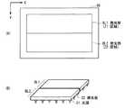
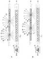
図2は、立体表示装置1の要部の一構成例を表すものであり、(A)は立体表示装置1の分解斜視構成を示し、(B)は立体表示装置1の側面図を示す。図2に示したように、立体表示装置1では、これらの各部品は、バックライト30、表示部20、および液晶バリア10の順に配置されている。つまり、バックライト30から射出した光は、表示部20および液晶バリア10を介して、観察者に届くようになっている。 FIG. 2 illustrates a configuration example of a main part of the
(表示駆動部50および表示部20)
図3は、表示駆動部50および表示部20のブロック図の一例を表すものである。表示駆動部50は、タイミング制御部51と、ゲートドライバ52と、データドライバ53とを備えている。タイミング制御部51は、ゲートドライバ52およびデータドライバ53の駆動タイミングを制御するとともに、制御部40から供給された映像信号Sを映像信号S1としてデータドライバ53へ供給するものである。ゲートドライバ52は、タイミング制御部51によるタイミング制御に従って、液晶表示デバイス45内の画素Pix(後述)を行ごとに順次選択して、線順次走査するものである。データドライバ53は、表示部20の各画素Pixへ、映像信号S1に基づく画素信号を供給するものである。具体的には、データドライバ53は、映像信号S1に基づいてD/A(デジタル/アナログ)変換を行うことにより、アナログ信号である画素信号を生成し、各画素Pixへ供給するようになっている。(
FIG. 3 illustrates an example of a block diagram of the
表示部20は、例えばガラスなどから構成される2枚の透明基板の間に液晶材料を封入したものである。これらの透明基板の液晶材料に面した部分には、例えばITO(Indium Tin Oxide)などから構成される透明電極が形成され、液晶材料とともに画素Pixを構成している。 The
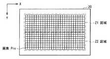
図4は、表示部20の一構成例を表すものである。図5は、画素Pixの回路図の一例を表すものである。表示部20には、図4に示したように、画素Pixがマトリックス状に配置されている。 FIG. 4 illustrates a configuration example of the
画素Pixは、図5に示したように、TFT(Thin Film Transistor)素子Trと、液晶素子LCと、保持容量素子Cとを備えている。TFT素子Trは、例えばMOS−FET(Metal Oxide Semiconductor-Field Effect Transistor)により構成されるものであり、ゲートがゲート線Gに接続され、ソースがデータ線Dに接続され、ドレインが液晶素子LCの一端と保持容量素子Cの一端に接続されている。液晶素子LCは、一端がTFT素子Trのドレインに接続され、他端は接地されている。保持容量素子Cは、一端がTFT素子Trのドレインに接続され、他端は保持容量線Csに接続されている。ゲート線Gはゲートドライバ52に接続され、データ線Dはデータドライバ53に接続されている。 As illustrated in FIG. 5, the pixel Pix includes a TFT (Thin Film Transistor) element Tr, a liquid crystal element LC, and a storage capacitor element C. The TFT element Tr is configured by, for example, a MOS-FET (Metal Oxide Semiconductor-Field Effect Transistor), the gate is connected to the gate line G, the source is connected to the data line D, and the drain is the liquid crystal element LC. One end and one end of the storage capacitor element C are connected. The liquid crystal element LC has one end connected to the drain of the TFT element Tr and the other end grounded. The storage capacitor element C has one end connected to the drain of the TFT element Tr and the other end connected to the storage capacitor line Cs. The gate line G is connected to the
図4に示した区域Z1,Z2は、詳細は後述するが、バックライト30の発光部BL1,BL2(後述)の位置に対応するものである。つまり、表示部20は、区域Z1に対して発光部BL1から射出した光が入射し、区域Z2に対して発光部BL2から射出した光が入射するように配置されている。 The zones Z1 and Z2 shown in FIG. 4 correspond to the positions of the light emitting portions BL1 and BL2 (described later) of the
この構成により、バックライト30から射出した光は、表示部20の入射側に配置された偏光板(図示せず)によって定められる方向の直線偏光となり、液晶素子LCに入射する。液晶素子LCでは、データ線Dを介して供給された画素信号に応じて、液晶分子の向きがある応答時間で変化する。このような液晶素子LCに入射した光は、その偏光方向が変化する。そして、液晶素子LCを透過した光は、表示部20の出射側に配置された偏光板(図示せず)に入射し、特定の偏光方向の光のみが通過する。このようにして、液晶素子LCでは光の強度変調が行われるようになっている。 With this configuration, light emitted from the
(バックライト30)
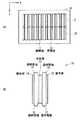
図6は、バックライト30の一構成例を表すものであり、(A)はバックライト30の平面図を示し、(B)はバックライト30の要部の斜視図を示す。バックライト30は、図6(A)に示したように、独立して発光可能な2つの発光部BL1,BL2を有している。発光部BL1,BL2は、図6(B)に示したように、それぞれ、光源31と、導光板32とを有している。光源31は、この例では、LED(Light Emitting Diode)により構成されている。導光板32は、光源31から射出した光を拡散することにより、発光部BL1,BL2がほぼ均一に面発光するように機能する。(Backlight 30)
FIG. 6 illustrates one configuration example of the
発光部BL1,BL2が独立して発光できるようにするため、バックライト30では、発光部BL1と発光部BL2との間で互いに光が伝わらないようになっている。具体的には、まず、1つの光源31から射出した光は、その光源31に対応する導光板32にのみ入射するようになっている。そして、導光板32に入射した光は、導光板32の側面において全反射するようになっており、これにより隣接する導光板32にこの側面を介して光が伝わらないようになっている。この全反射は、具体的には、光源31の位置を調整し、あるいは、導光板32の側面に光反射を起こす反射面を設けることにより実現可能である。なお、この例では、光源31はLEDにより構成されるものとしたが、これに限定されるものではなく、これに代えて、例えばCCFL(Cold Cathode Fluorescent Lamp)により構成されるようにしてもよい。 In order to enable the light emitting portions BL1 and BL2 to emit light independently, the
発光部BL1,BL2は、図4に示した区域Z1,Z2に対応するものである。つまり、発光部BL1から射出した光は表示部20の区域Z1に入射し、発光部BL2から射出した光は表示部20の区域Z2に入射する。つまり、表示部20の区域Z1に配置された画素Pixは、発光部BL1から射出した光に基づいて表示を行い、同様に、区域Z2に配置された画素Pixは、発光部BL2から射出した光に基づいて表示を行うようになっている。 The light emitting portions BL1 and BL2 correspond to the zones Z1 and Z2 shown in FIG. That is, the light emitted from the light emitting unit BL1 enters the zone Z1 of the
この構成により、バックライト駆動部29がバックライト30の発光部BL1,BL2を互いに異なるタイミングで駆動することにより、立体表示装置1は、区域Z1における表示と、区域Z2における表示とを、互いに異なるタイミングで行うようになっている。 With this configuration, the
(液晶バリア10)
図7は、液晶バリア10の一構成例を表すものであり、(A)は液晶バリア10の平面図を示し、(B)は側面図を示す。なお、この例では、液晶バリア10はノーマリーブラック動作を行うものとする。つまり、液晶バリア10は、駆動されていない状態では光を遮断するものとする。(Liquid crystal barrier 10)
FIG. 7 illustrates one configuration example of the
液晶バリア10は、図7(A)に示したように、光を透過または遮断する複数の開閉部11,12を有している。開閉部11,12は、立体表示装置1が通常表示(2次元表示)および立体視表示のどちらを行うかにより、異なる動作を行う。具体的には、開閉部11は、後述するように、立体表示装置1が通常表示を行う際に開放状態(透過状態)になり、立体視表示を行う際には、閉状態(遮断状態)となるものである。開閉部12は、後述するように、立体表示装置1が通常表示を行う際に開放状態(透過状態)になり、立体視表示を行う際には、時分割的に開閉動作を行うものである。 As shown in FIG. 7A, the
液晶バリア10は、図7(B)に示したように、透明基板13と、透明基板13に対向して配置された透明基板16と、透明基板13と透明基板16との間に挿設された液晶層19とを備えている。透明基板13,16は、例えばガラスなどから構成されるものである。透明基板13の液晶層19側の面、および透明基板16の液晶層19側の面には、例えばITOなどから構成される複数の透明電極15,17がそれぞれ形成されている。透明基板13上に形成された透明電極15と、透明基板16上に形成された透明電極17とは、互いに対応する位置に配置されており、液晶層19とともに開閉部11,12を構成している。透明基板13の液晶層19とは反対側の面、および透明基板16の液晶層19とは反対側の面には、偏光板14,18がそれぞれ形成されている。なお、図示していないが、図7(B)において、液晶バリア10の右側(偏光板18の右側)には、表示部20およびバックライト30が図2(B)に示した順に配置されている。 As shown in FIG. 7B, the
液晶バリア10の開閉部11,12の開閉動作は、表示部20における表示動作と同様である。すなわち、バックライト30から射出し表示部20を透過した光は、偏光板18によって定められる方向の直線偏光となり、液晶層19に入射する。液晶層19では、透明電極15,17に供給された電位差に応じて、液晶分子の向きがある応答時間で変化する。このような液晶層19に入射した光は、その偏光方向が変化する。そして、液晶層19を透過した光は、偏光板14に入射し、特定の偏光方向の光のみが通過する。このようにして、液晶層19では光の強度変調が行われるようになっている。 The opening / closing operation of the opening /
この構成により、透明電極15,17に電圧を印加してその電位差を大きくなると、液晶層19における光の透過率が増大し、開閉部11,12は透過状態になる。一方、透明電極15,17間の電位差が小さくなると、液晶層19における光の透過率が減少し、開閉部11,12は遮断状態となる。 With this configuration, when a voltage is applied to the
なお、この例では、液晶バリア10はノーマリーブラック動作を行うものとしたが、これに限定されるものではなく、これに代えて、例えばノーマリーホワイト動作を行うものであってもよい。この場合には、透明電極15,17間の電位差が大きくなると、開閉部11,12は遮断状態となり、透明電極15,17間の電位差が小さくなると、開閉部11,12は透過状態となる。なお、ノーマリーブラック動作とノーマリーホワイト動作の選択は、例えば、偏光板と液晶配向により設定することができる。 In this example, the
図7(A)に示した区域Z1,Z2は、図4に示した表示部20の場合と同様に、バックライト30の発光部BL1,BL2の位置に対応するものである。つまり、液晶バリア10は、液晶バリア10の区域Z1に対して発光部BL1から射出した光が表示部20を介して入射し、区域Z2に対して発光部BL2から射出した光が表示部20を介して入射するように配置されている。 Zones Z1 and Z2 shown in FIG. 7A correspond to the positions of the light emitting parts BL1 and BL2 of the
液晶バリア10では、区域Z1に配置された開閉部12と、区域Z2に配置された開閉部12とは、互いに独立して動作できるようになっている。バリア駆動部9は、これらの開閉部12を独立に駆動することにより、立体視表示を行う際、区域Z1の開閉部12が開閉動作を行うタイミングと、区域Z2の開閉部12が開閉動作を行うタイミングとが互いに異なるようにすることができる。 In the
区域Z1,Z2のそれぞれにおいて、複数の開閉部12はグループを形成する。同じグループに属する複数の開閉部12は、立体視表示を行う際、同じタイミングで開動作および閉動作を行うようになっている。以下に、開閉部12のグループについて説明する。 In each of the zones Z1 and Z2, the plurality of opening /
図8は、開閉部12のグループ構成例を表すものである。区域Z1,Z2のそれぞれにおいて、開閉部12は、この例では2つのグループを形成している。具体的には、区域Z1において、1つおきに配置された複数の開閉部12が、グループA1およびグループB1をそれぞれ形成している。同様に、区域Z2において、1つおきに配置された複数の開閉部12が、グループA2およびグループB2をそれぞれ形成している。 FIG. 8 illustrates a group configuration example of the opening /
バリア駆動部9は、立体視表示を行う際、同じグループに属する複数の開閉部12が同じタイミングで開閉動作を行うように駆動する。具体的には、区域Z1において、バリア駆動部9は、後述するように、グループA1に属する複数の開閉部12と、グループB1に属する複数の開閉部12とを、時分割的に交互に開閉動作するように駆動する。このように、同じグループに属する複数の開閉部12が同じタイミングで動作するためには、例えば、バリア駆動部9が、同じグループに属する複数の開閉部12の透明電極15,17に対して、同時に駆動信号を印加すればよい。また、同じグループに属する複数の開閉部12の透明電極15,17を互いに結線することにより、同時に駆動信号を印加するようにしてもよい。 When performing stereoscopic display, the
なお、以下では、グループA1,A2の総称としてグループAを適宜用い、同様に、グループB1,B2の総称としてグループBを適宜用いるものとする。また、グループA(グループA1,A2)に属する開閉部12の総称として開閉部12Aを適宜用い、同様に、グループB(グループB1,B2)に属する開閉部12の総称として開閉部12Bを適宜用いるものとする。 In the following, it is assumed that group A is appropriately used as a general term for groups A1 and A2, and similarly, group B is appropriately used as a general term for groups B1 and B2. Further, the opening /
図9は、立体視表示および通常表示(2次元表示)を行う場合の液晶バリア10の状態を、断面構造を用いて模式的に表すものであり、(A)は立体視表示を行う一状態を示し、(B)は立体視表示を行う他の状態を示し、(C)は通常表示を行う状態を示す。液晶バリア10には、開閉部11および開閉部12(開閉部12A,12B)が交互に配置されている。この例では、開閉部12Aは、表示部20の6つの画素Pixに1つの割合で設けられている。同様に、開閉部12Bは、表示部20の6つの画素Pixに1つの割合で設けられている。以下の説明では、画素Pixは、3つのサブピクセル(RGB)から構成されたピクセルとするが、これに限定されるものではなく、例えば、画素Pixがサブピクセルであってもよい。また、液晶バリア10において、光が遮断される部分は斜線で示している。 FIG. 9 schematically illustrates the state of the
立体視表示を行う場合には、表示駆動部50に映像信号SA,SBが交互に供給され、液晶バリア10では、開閉部12(開閉部12A,12B)が時分割的に開閉動作を行い、開閉部11が閉状態(遮断状態)を維持する。具体的には、映像信号SAが供給された場合には、図9(A)に示したように、開閉部12Aが開状態になるとともに、開閉部12Bが閉状態になる。表示部20では、この開閉部12Aに対応した位置に配置された互いに隣接する6つの画素Pixが、映像信号SAに含まれる6つの視点映像に対応する表示を行う。これにより、観察者は、後述するように、例えば左眼と右眼とで異なる視点映像を見ることにより、表示された映像を立体的な映像として感じるようになっている。同様に、映像信号SBが供給された場合には、図9(B)に示したように、開閉部12Bが開状態になるとともに、開閉部12Aが閉状態になる。表示部20では、この開閉部12Bに対応した位置に配置された互いに隣接する6つの画素Pixが、映像信号SBに含まれる6つの視点映像に対応する表示を行う。これにより、観察者は、後述するように、例えば左眼と右眼とで異なる視点映像を見ることにより、表示された映像を立体的な映像として感じるようになっている。立体表示装置1では、このように、開閉部12Aと開閉部12Bを交互に開放して映像を表示することにより、後述するように、表示装置の解像度を高めることができるようになっている。 When performing stereoscopic display, video signals SA and SB are alternately supplied to the
通常表示(2次元表示)を行う場合には、液晶バリア10では、図9(C)に示したように、開閉部11および開閉部12(開閉部12A,12B)はともに開放状態(透過状態)を維持するようになっている。これにより、観察者は、映像信号Sに基づいて表示部20に表示された通常の2次元映像をそのまま見ることができる。 When normal display (two-dimensional display) is performed, in the
なお、図9に示したように、開閉部11と開閉部12との間には、開閉部境界23が設けられている。この開閉部境界23では、透明基板13,16上に透明電極15,17がそれぞれ形成されていない。つまり、開閉部境界23は、開閉部11と開閉部12とは異なり、開閉動作を行うことができず、ノーマリーブラック動作を行う液晶バリア10では常に閉状態(遮断状態)となる。一方、ノーマリーホワイト動作を行う液晶バリア10では常に開放状態(透過状態)となる。この開閉部境界23は、開閉部11,12に比べて十分に小さいものであるため、観察者が気になることはほとんどない。これ以降の図および説明では、この開閉部境界23を適宜省略することとする。 As shown in FIG. 9, an opening / closing
ここで、バックライト30における区域Z1,Z2は、本発明における「サブ発光領域」の一具体例に対応する。グループA1,B1,A2,B2は、本発明における「開閉部グループ」の一具体例に対応する。液晶バリア10は、本発明における「光バリア部」の一具体例に対応する。バリア駆動部9は、本発明における「光バリア駆動部」の一具体例に対応する。バックライト駆動部29は、本発明における「バックライト制御部」の一具体例に対応する。液晶バリア10における区域Z1,Z2は、本発明における「サブバリア領域」の一具体例に対応する。 Here, the zones Z1 and Z2 in the
[動作および作用]
続いて、本実施の形態の立体表示装置1の動作および作用について説明する。[Operation and Action]
Next, the operation and action of the
(全体動作概要)
制御部40は、外部より供給される映像信号Vdispに基づいて、表示駆動部50、バックライト駆動部29、およびバリア駆動部9に対してそれぞれ制御信号を供給し、これらがお互いに同期して動作するように制御する。バックライト駆動部29は、制御部40から供給されるバックライト制御信号に基づいてバックライト30を駆動する。バックライト30は、面発光した光を表示部20に対して射出する。表示駆動部50は、制御部40から供給される映像信号Sに基づいて表示部20を駆動する。表示部20は、バックライト30から射出した光を変調することにより表示を行う。バリア駆動部9は、制御部40から供給されるバリア制御命令に基づいて液晶バリア10を駆動する。液晶バリア10は、バックライト30から射出し表示部20を透過した光を、透過または遮断する。(Overview of overall operation)
The
(立体視表示の詳細動作)
次に、いくつかの図を参照して、立体視表示を行う場合の詳細動作を説明する。(Detailed operation of stereoscopic display)
Next, a detailed operation when performing stereoscopic display will be described with reference to several drawings.
図10は、表示部20および液晶バリア10の動作例を表すものであり、(A)は、映像信号SAが供給された場合を示し、(B)は映像信号SBが供給された場合を示す。 10A and 10B show an example of the operation of the
映像信号SAが供給された場合には、図10(A)に示したように、表示部20の画素Pixのそれぞれは、映像信号SAに含まれる6つの視点映像のそれぞれに対応する画素情報P1〜P6を表示する。このとき、画素情報P1〜P6は、開閉部12A付近に配置された画素Pixにそれぞれ表示される。映像信号SAが供給された場合には、液晶バリア10では、開放部12Aが開放状態(透過状態)になるとともに、開放部12Bが閉状態になるように制御されている。表示部20の各画素Pixから出た光は、開閉部12Aによりそれぞれ角度が制限されて出力される。観察者は、例えば左眼で画素情報P3を、右眼で画素情報P4を見ることにより、立体的な映像を見ることができる。 When the video signal SA is supplied, as shown in FIG. 10A, each of the pixels Pix of the
映像信号SBが供給された場合には、図10(B)に示したように、表示部20の画素Pixのそれぞれは、映像信号SBに含まれる6つの視点映像のそれぞれに対応する画素情報P1〜P6を表示する。このとき、画素情報P1〜P6は、開閉部12B付近に配置された画素Pixにそれぞれ表示される。映像信号SBが供給された場合には、液晶バリア10では、開放部12Bが開放状態(透過状態)になるとともに、開放部12Aが閉状態になるように制御されている。表示部20の各画素Pixから出た光は、開閉部12Bによりそれぞれ角度が制限されて出力される。観察者は、例えば左眼で画素情報P3を、右眼で画素情報P4を見ることにより、立体的な映像を見ることができる。 When the video signal SB is supplied, as shown in FIG. 10B, each of the pixels Pix of the
このように、観察者は、左眼と右眼とで、画素情報P1〜P6のうちの異なる画素情報を見ることとなり、観察者は立体的な映像として感じることができる。また、開閉部12Aと開閉部12Bを時分割的に交互に開放して映像を表示することにより、観察者は、互いにずれた位置に表示される映像を平均化して見ることとなる。よって、立体表示装置1は、開口部12Aのみをもつ場合に比べ、2倍の解像度を実現することが可能となる。言い換えれば、立体表示装置1の解像度は、2次元表示の場合に比べ1/3(=1/6×2)で済むこととなる。 Thus, the observer sees different pixel information among the pixel information P1 to P6 with the left eye and the right eye, and the observer can feel as a stereoscopic image. Also, by opening and closing the opening /
次に、液晶バリア10、表示部20、およびバックライト30における、区域Z1,Z2の各区域の動作を詳細に説明する。 Next, the operation of each of the zones Z1 and Z2 in the
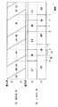
図11は、表示部20における表示動作を表すものである。縦軸は、表示部20の線順次走査方向(y軸方向)(図4)の位置を示し、横軸は時間を示す。つまり、図11は、ある時刻の、あるy軸方向の位置における、表示動作状態を示している。図11において、“SA”は映像信号SAに基づく表示を行っている状態を示し、“SB”は映像信号SBに基づく表示を行っている状態を示している。また、“SA→SB”は、表示駆動部50に映像信号SBが供給され、映像信号SAに基づく表示から映像信号SBに基づく表示に変化している状態を示している。同様に、“SB→SA”は、表示駆動部50に映像信号SAが供給され、映像信号SBに基づく表示から映像信号SAに基づく表示に変化している状態を示している。この“SA→SB”および“SB→SA”は、液晶分子の応答時間τに対応するものである。 FIG. 11 shows a display operation in the
表示部20は、時刻aから時刻iまでの間、表示部20の最上部から最下部に向かって線順次走査を行い、映像信号SBに基づく表示から映像信号SAに基づく表示に切り換わる。 The
まず、時刻aでは、表示部20は、図11に示したように、y軸方向の全ての位置において、映像信号SBに基づく表示を行う。つまり、表示部20の表示面全体にわたり、映像信号SBに基づく表示を行っていることを示している。 First, at time a, the
その後、表示部20では、最上部から各画素Pixに対して映像信号SAに基づく画素信号が順次印加され、映像信号SBに基づく表示から映像信号SAに基づく表示に変化していく。例えば、時刻cでは、区域Z1(表示部20の上部)は、映像信号SBに基づく表示から映像信号SAに基づく表示に変化している状態となり、一方、区域Z2(表示部20の下部)は、引き続き映像信号SBに基づく表示を行う。つまり、区域Z1の画素Pixには、映像信号SAに応じた画素信号が印加されているが、液晶の応答速度が遅く、表示はすぐに切り換わることはできないため、このように過渡的な状態となっている。 Thereafter, in the
そして、時刻eでは、表示部20の表示面全体が、映像信号SBに基づく表示から映像信号SAに基づく表示に変化している状態となる。 At time e, the entire display surface of the
その後、表示部20では、最上部から液晶の応答が順次終了し、映像信号SAに基づく表示を行う。例えば、時刻gでは、区域Z1(表示部20の上部)は、映像信号SBに基づく表示から映像信号SAに基づく表示に切り換わり、一方、区域Z2(表示部20の下部)は、引き続き、映像信号SBに基づく表示から映像信号SAに基づく表示に変化している状態を維持する。 Thereafter, in the
そして、時刻iでは、表示部20の表示面全体において、映像信号SBに基づく表示から映像信号SAに基づく表示に切り換わる。すなわち、表示部20は、映像信号SAに基づく表示を行う。 At time i, the entire display surface of the
次に、表示部20は、時刻jから時刻rまでの間、同様に、表示部20の最上部から最下部に向かって線順次走査を行い、映像信号SAに基づく表示から映像信号SBに基づく表示に切り換わる。 Next, the
表示部20は、上述した時刻aから時刻rまでの動作を繰り返すことにより、映像信号SAに基づく表示および映像信号SBに基づく表示を交互に繰り返す。 The
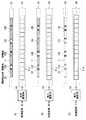
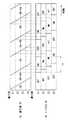
図12は、立体表示装置1における表示動作を表すものであり、(A)は表示部20の状態を示し、(B)は液晶バリア10の状態を示し、(C)はバックライト30の状態を示す。 図12(A)において、“SA”、“SB”、“SA→SB”、および“SB→SA”は、図11に示したものと同様である。図12(B)において、“A1”は、液晶バリア10のグループA1に属する開閉部12が開放し、グループB1に属する開閉部12が遮断している状態を示す。“B1”は、液晶バリア10のグループB1に属する開閉部12が開放し、グループA1に属する開閉部12が遮断している状態を示す。“A1→B1”は、グループB1に属する開閉部12が遮断から開放へ変化するとともに、グループA1に属する開閉部12が開放から遮断へ変化している状態を示す。“B1→A1”は、グループA1に属する開閉部12が遮断から開放へ変化するとともに、グループB1に属する開閉部12が開放から遮断へ変化している状態を示す。図12(B)において、“A2”、“B2”、“A2→B2”、および“B2→A2”は、これらと同様である。すなわち、“A2”は、液晶バリア10のグループA2に属する開閉部12が開放し、グループB2に属する開閉部12が遮断している状態を示す。“B2”は、液晶バリア10のグループB2に属する開閉部12が開放し、グループA2に属する開閉部12が遮断している状態を示す。“A2→B2”は、グループB2に属する開閉部12が遮断から開放へ変化するとともに、グループA2に属する開閉部12が開放から遮断へ変化している状態を示す。“B2→A2”は、グループA2に属する開閉部12が遮断から開放へ変化するとともに、グループB2に属する開閉部12が開放から遮断へ変化している状態を示す。図12(C)において、“ON”はバックライト30の発光部BL1,BL2が発光している状態を示し、“OFF”は消灯している状態を示す。つまり、例えば、区域Z1における“ON”は、発光部BL1が発光していることを示し、区域Z2における“ON”は発光部BL2が発光していることを示す。時刻a〜rは、図11と対応するものである。 FIG. 12 illustrates a display operation in the
まず、時刻aから時刻iまでの間、表示部20では、表示駆動部50から供給される駆動信号に基づき、最上部から最下部に向かって線順次走査を行われ、映像信号SBに基づく表示から映像信号SAに基づく表示に変化する。液晶バリア10では、バリア駆動部9から供給される駆動信号に基づき、表示部20における表示の変化状態に対応するように、グループA(グループA1,A2)に属する開閉部12が遮断から開放へ変化するとともに、グループB(グループB1,B2)に属する開閉部12が開放から遮断へ変化する。バックライト30は、バックライト駆動部29から供給される駆動信号に基づき、区域Z1,Z2における表示部20および液晶バリア10の状態に対応するように、発光部BL1,BL2を発光する。 First, from time a to time i, the
時刻aにおいて、表示部20は、表示面全体にわたり映像信号SBに基づく表示を行う。液晶バリア10では、映像信号SBに対応するグループB1,B2に属する開閉部12が開放状態になるとともに、グループA1,A2に属する開閉部12が遮断状態になっている。バックライト30は、区域Z1,Z2の発光部BL1,BL2がともに発光状態になっている。これにより、立体表示装置1では、映像信号SBに基づく表示が行われる。 At time a, the
時刻bにおいて、表示部20の上部から1/4の部分(区域Z1の半分)が、映像信号SBに基づく表示から映像信号SAに基づく表示に変化している状態となる。液晶バリア10では、表示部20において上述した変化が始まった区域Z1では、映像信号SAに係るグループA1に属する開閉部12が遮断から開放へ変化するとともに、映像信号SBに係るグループB1に属する開閉部12が開放から遮断へ変化している状態となる。つまり、区域Z1のグループA1,B1に属する開閉部12は、表示部20と同様に、液晶の応答速度が遅く、その状態がすぐに切り替わることができないため、このような過渡的な状態となる。バックライト30では、表示部20および液晶バリア10において上述した変化が始まった区域Z1に対応する発光部BL1が消灯する。これにより、観察者は、表示部20および液晶バリア10の上述した変化状態を見ることがないので、画質劣化を低減することができる。 At time “b”, a ¼ portion (half of the zone Z1) from the top of the
時刻cにおいて、表示部20の区域Z1は、映像信号SBに基づく表示から映像信号SAに基づく表示に変化している状態となる。液晶バリア10およびバックライト30は、時刻bと同様の状態である。 At time c, the zone Z1 of the
時刻dにおいて、表示部20の上部から3/4の部分(区域Z1の全体および区域Z2の半分)は、映像信号SBに基づく表示から映像信号SAに基づく表示に変化している状態となる。液晶バリア10の区域Z1では、グループA1,B1に属する開閉部12が引き続き変化し、表示部20において上述した変化が始まった区域Z2では、映像信号SAに係るグループA2に属する開閉部12が遮断から開放へ変化するとともに、映像信号SBに係るグループB2に属する開閉部12が開放から遮断へ変化している状態となる。バックライト30では、表示部20および液晶バリア10において上述した変化が生じている区域Z1,Z2全体に対応する発光部BL1,BL2がともに消灯する。これにより、観察者は、表示部20および液晶バリア10の上述した変化状態を見ることはないので、画質劣化を低減することができる。 At time d, a portion of 3/4 from the upper part of the display unit 20 (the whole of the zone Z1 and half of the zone Z2) is changed from the display based on the video signal SB to the display based on the video signal SA. In the zone Z1 of the
時刻eにおいて、表示部20の表示面全体が、映像信号SBに基づく表示から映像信号SAに基づく表示に変化している状態となる。液晶バリア10およびバックライト30は、時刻dと同様の状態である。 At time e, the entire display surface of the
時刻fにおいて、表示部20の上部から1/4の部分(区域Z1の半分)では、表示が変化が終了して映像信号SAに基づく表示を行い、その他の3/4の部分(区域Z1の半分および区域Z2全体)では、表示が引き続き変化する。液晶バリア10およびバックライト30は、時刻eと同様の状態である。 At time f, in the ¼ portion from the upper part of the display unit 20 (half of the zone Z1), the display is changed and display is performed based on the video signal SA, and the other 3/4 portion (in the zone Z1). In half and the whole zone Z2, the display continues to change. The
時刻gにおいて、表示部20の区域Z1では、表示の変化が終了して映像信号SAに基づく表示を行い、区域Z2では表示が引き続き変化する。液晶バリア10の区域Z1では、開閉状態の変化が終了し、映像信号SAに係るグループA1に属する開閉部12が開放状態となる。液晶バリア10の区域Z2では、開閉状態が引き続き変化する。バックライト30では、表示部20および液晶バリア10において上述した変化が終了した区域Z1に対応する発光部BL1が発光する。 At time g, the display change is completed in the zone Z1 of the
時刻hにおいて、表示部20の上部から3/4の部分(区域Z1の全体および区域Z2の半分)では、表示の変化が終了して映像信号SAに基づく表示を行い、残りの1/4の部分(区域Z2の半分)では表示が引き続き変化する。液晶バリア10およびバックライト30は、時刻gと同様の状態である。 At time h, in the ¾ portion from the upper part of the display unit 20 (the whole of the zone Z1 and half of the zone Z2), the change of the display is finished and the display based on the video signal SA is performed, and the remaining ¼ The display continues to change in the part (half of zone Z2). The
時刻iにおいて、表示部20では、表示面全体にわたり表示の変化が終了し、映像信号SAに基づく表示を行う。液晶バリア10では、区域Z1,Z2全体にわたり開閉状態の変化が終了し、映像信号SAに係るグループA1,A2に属する開閉部12が開放状態になるとともに、映像信号SBに係るグループB1,B2に属する開閉部12が遮断状態になる。バックライト30では、表示部20および液晶バリア10において上述した変化が終了した区域Z2に対応する発光部BL2が発光する。これにより、区域Z1,Z2全体に対応する発光部BL1,BL2が発光する。 At time i, the
次に、時刻jから時刻rまでの間、表示部20では、上述した時刻aから時刻iまでの間と同様に、表示駆動部50から供給される駆動信号に基づき、最上部から最下部に向かって線順次走査が行われ、映像信号SBに基づく表示から映像信号SAに基づく表示に変化する。液晶バリア10では、バリア駆動部9から供給される駆動信号に基づき、表示部20における表示の変化状態に対応するように、グループB(グループB1,B2)に属する開閉部12が遮断から開放へ変化するとともに、グループA(グループA1,A2)に属する開閉部12を開放から遮断へ変化する。バックライト30は、バックライト駆動部29から供給される駆動信号に基づき、区域Z1,Z2における表示部20および液晶バリア10の状態に対応するように、発光部BL1,BL2を発光する。 Next, during the period from time j to time r, the
立体表示装置1は、上述した時刻aから時刻rまでの動作を繰り返すことにより、映像信号SAに基づく表示および映像信号SBに基づく表示を交互に繰り返す。 The
図13は、表示部20の表示状態とバックライト30の発光状態との関係を表すものであり、(A)は表示部20の表示状態を示し、(B)はバックライト30の発光状態を示す。図13(B)に示したように、バックライト30の区域Z1に対応する発光部BL1は、例えば時刻gから時刻jの間(時間T0)で発光し、区域Z2に対応する発光部BL2は、例えば時刻iから時刻lの間(時間T0)で発光する。このように、表示部20の線順次走査方向に対してバックライト30を分割し、走査に合わせてそれぞれを独立して発光するようにしたので、発光時間を長くすることができ、輝度を高めることができる。 FIG. 13 shows the relationship between the display state of the
(比較例)
図14は、(本発明を利用しない)比較例に係る立体表示装置1Rの一構成例を表すものである。本比較例では、表示部の線順次走査方向に対して分割されていないバックライトを用いて立体表示装置1Rを構成している。なお、上記第1の実施の形態に係る立体表示装置1(図1など)と実質的に同一の構成部分には同一の符号を付し、適宜説明を省略する。(Comparative example)
FIG. 14 illustrates a configuration example of a stereoscopic display device 1R according to a comparative example (not using the present invention). In this comparative example, the
立体表示装置1Rは、バックライト30Rと、液晶バリア10Rとを備えている。バックライト30Rは、上記実施の形態に係るバックライト30(図6)とは異なり、表示部の線順次走査方向(y軸方向)において、発光部が分割されていないものであり、バックライト30Rの全面から同時に光を射出し、または消灯するものである。このバックライト30Rは、バックライト駆動部29Rにより駆動されるようになっている。液晶バリア10Rは、バックライト30Rと同様に、表示部の線順次走査方向(y軸方向)において、開閉部12が分割されていないものである。この液晶バリア10Rは、バリア駆動部9Rにより駆動されるようになっている。 The stereoscopic display device 1R includes a
図15は、比較例に係る表示部20の表示状態とバックライト30Rの発光状態との関係を表すものであり、(A)は表示部20の表示状態を示し、(B)はバックライト30Rの発光状態を示す。図15(B)に示したように、バックライト30Rは、液晶の過渡応答に起因する画質劣化を抑えるため、例えば時刻iから時刻jの間のみで発光する。具体的には、この例では、表示部20の最下部において映像信号SBに基づく表示から映像信号SAに基づく表示に切り替わった後(時刻i)、最上部において映像信号SAに基づく表示から映像信号SBに基づく表示への変化を開始するまで(時刻j)の間に発光する。この発光時間(時間T1)は、この例では、本実施の形態に係る立体表示装置1の場合(図13)の発光時間(時間T0)と比べて半分程度にまで短くなっている。この場合、立体表示装置の輝度が低くなってしまう。 FIG. 15 shows the relationship between the display state of the
一方、本実施の形態に係る立体表示装置1では、表示部20の線順次走査向に対してバックライト30を分割し、独立して発光できるようにしている。これにより、分割したバックライト30(発光部BL1,BL2)のそれぞれに対して、別々の発光タイミングを設定でき、各発光部BL1,BL2の発光時間を長くすることにより、輝度を高めることができる。 On the other hand, in the
[効果]
以上のように、本実施の形態では、表示部20の線順次走査向に対してバックライト30および液晶バリア10をそれぞれ分割し、その分割した各領域を独立して駆動するようにしたので、液晶の過渡応答に起因する画質の低下を抑えつつ、輝度を高めることができる。[effect]
As described above, in the present embodiment, the
[変形例1]
上記実施の形態では、表示部20の線順次走査向に対して、バックライト30および液晶バリア10の開閉部12を2分割したが、これに限定されるものではなく、例えば、3以上に分割してもよい。以下に、4分割する場合の例を示す。[Modification 1]
In the above embodiment, the
図16は、本変形例に係る表示部の表示状態とバックライトの発光状態との関係を表すものであり、(A)は表示部の表示状態を示し、(B)はバックライトの発光状態を示す。本変形例では、バックライトおよび液晶バリアの開閉部を、表示部の線順次走査向に対して、4つの区域Z1〜Z4に分割している。これにより、バックライトの発光時間(時間T2)は、この例では、図16(B)に示したように、上記実施の形態の場合(図13)の発光時間(T0)に比べて1.3倍程度になっており、長くなっている。このように、分割数を増やすことにより、発光時間を長くすることができ、輝度を高めることができる。 FIG. 16 shows the relationship between the display state of the display unit and the light emission state of the backlight according to this modification. (A) shows the display state of the display unit, and (B) shows the light emission state of the backlight. Indicates. In this modification, the opening and closing parts of the backlight and the liquid crystal barrier are divided into four zones Z1 to Z4 with respect to the line sequential scanning direction of the display part. Thereby, the light emission time (time T2) of the backlight is 1. in this example as compared with the light emission time (T0) of the above embodiment (FIG. 13) as shown in FIG. It is about 3 times longer and longer. Thus, by increasing the number of divisions, the light emission time can be lengthened and the luminance can be increased.
[変形例2]
上記実施の形態では、立体表示装置1のバックライト30、表示部20、液晶バリア10は、この順に配置したが、これに限定されるものではなく、これに代えて、例えば、図17に示したように、バックライト30、液晶バリア10、表示部20の順に配置してもよい。[Modification 2]
In the above embodiment, the
図18は、本変形例に係る表示部20および液晶バリア10の動作例を表すものであり、(A)は、映像信号SAが供給された場合を示し、(B)は映像信号SBが供給された場合を示す。本変形例では、バックライト30から射出した光は、まず液晶バリア10に入射する。そして、その光のうち、開閉部12A,12Bを透過した光が表示部20において変調されるとともに、6つの視点映像を出力するようになっている。 18A and 18B show an example of the operation of the
[変形例3]
上記実施の形態では、表示部20の線順次走査方向(y軸方向)に対してのみ分割されているバックライトを用いたが、これに限定されるものではなく、y軸方向に加え、x軸方向にも分割されているバックライトを用いてもよい。[Modification 3]
In the above embodiment, the backlight that is divided only in the line sequential scanning direction (y-axis direction) of the
図19は、x軸方向とy軸方向の両方の方向に対して分割されたバックライトの一構成例を表すものである。この例では、バックライトは、x軸方向に5分割されるとともに、y軸に4分割されている。このようなバックライトは、例えば、画面の半分が暗いような映像があったときに、その部分のバックライトの輝度を落としたり消灯したりすることにより消費電力を削減する目的で、従来からしばしば使用されるものである。このようなバックライトを用いても、上記実施の形態と同様の効果を得ることができる。すなわち、図19に示したように、このバックライトに、上記実施の形態に係るバックライト30の場合(図6)と同様に区域Z1,Z2に定義し、区域Z1と区域Z2とを独立して制御することにより、上記実施の形態と同様の効果を得ることができる。 FIG. 19 shows a configuration example of the backlight divided in both the x-axis direction and the y-axis direction. In this example, the backlight is divided into five in the x-axis direction and four in the y-axis. Such a backlight has often been used for the purpose of reducing power consumption by reducing the brightness of the backlight or turning it off when there is an image with half of the screen dark, for example. It is what is used. Even if such a backlight is used, the same effect as that of the above embodiment can be obtained. That is, as shown in FIG. 19, the backlight is defined as zones Z1 and Z2 as in the case of the
なお、上記実施の形態では、表示部20は線順次に書き込みを行うものとしたが、これに代えて、例えば点順次に書き込みを行う場合には、表示部20のx軸方向に加え、y軸方向についても独立して制御することにより、上記実施の形態と同様に、液晶の過渡応答に起因する画質劣化を抑えつつ、輝度を高めることができる。 In the above embodiment, the
[変形例4]
上記実施の形態では、液晶バリアの開閉部はy軸方向に延伸するものとしたが、これに限定されるものではなく、これに代えて、例えば、図20(A)に示したステップバリア形式や、図20(B)に示した斜めバリア形式であってもよい。ステップバリア形式については、例えば、特開2004−264762に記載がある。また、斜めバリア形式については、例えば、特開2005−86506に記載がある。[Modification 4]
In the above embodiment, the opening / closing part of the liquid crystal barrier extends in the y-axis direction. However, the present invention is not limited to this, and instead of this, for example, the step barrier type shown in FIG. Alternatively, the oblique barrier type shown in FIG. The step barrier format is described in, for example, Japanese Patent Application Laid-Open No. 2004-264762. The oblique barrier type is described in, for example, JP-A-2005-86506.
[変形例5]
例えば、上記実施の形態では、区域Z1,Z2のそれぞれにおいて、開閉部12は2つのグループを構成したが、これに限定されるものではなく、これに代えて、例えば3つ以上のグループを構成するようにしてもよい。これにより、表示の分解能をさらに改善することができる。図21は、開閉部12が3つのグループA,B,Cを構成する場合の例を表すものである。上記実施の形態と同様に、開閉部12AはグループAに属する開閉部12を示し、開閉部12BはグループBに属する開閉部12を示し、開閉部12CはグループCに属する開閉部12を示す。開閉部12A,12B,12Cを時分割的に交互に開放して映像を表示することにより、この変形例に係る立体表示装置は、開口部12Aのみをもつ場合に比べ、3倍の解像度を実現することが可能となる。言い換えれば、この立体表示装置の解像度は、2次元表示の場合に比べ1/2(=1/6×3)で済むこととなる。[Modification 5]
For example, in the above-described embodiment, in each of the zones Z1 and Z2, the opening / closing
[変形例6]
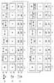
また、例えば、上記実施の形態では、表示部20は液晶を用いるものとしたが、これに限定されるものではない。図22は、応答時間が早い表示部20Dを用いた場合の表示動作を表すものである。時刻aから時刻eまでの間、表示部20Dでは、表示駆動部から供給される駆動信号に基づき、最上部から最下部に向かって線順次走査を行われ、映像信号SBに基づく表示から映像信号SAに基づく表示に、短い応答時間で切り換わる。同様に、時刻jから時刻nまでの間、表示部20Dでは、表示駆動部から供給される駆動信号に基づき、最上部から最下部に向かって線順次走査を行われ、映像信号SAに基づく表示から映像信号SBに基づく表示に、短い応答時間で切り換わる。この場合、バックライト30の発光部BL1,BL2は、液晶バリア10の開閉部12が変化している状態(“B1→A1”、“A1→B1”、“B2→A2”、“A2→B2”)では消灯し、それ以外のときには発光する。[Modification 6]
Further, for example, in the above embodiment, the
[変形例7]
また、例えば、上記実施の形態では、液晶により構成された液晶バリア10を用いるようにしたが、これに限定されるものではない。図23は、開閉部の応答時間が早いバリア10Eを用いた場合の表示動作を表すものである。このバリア10Eは、線順次走査方向に分割されていないものである。時刻bにおいて、バリア10Eでは、映像信号SAに係るグループAに属する開閉部12が遮断から開放へ短い応答時間で切り換わるとともに、映像信号SBに係るグループBに属する開閉部12が開放から遮断へ短い応答時間で切り換わる。また、時刻kにおいて、バリア10Eでは、映像信号SBに係るグループBに属する開閉部12が遮断から開放へ短い応答時間で切り換わるとともに、映像信号SAに係るグループAに属する開閉部12が開放から遮断へ短い応答時間で切り換わる。この場合、バックライト30の発光部BL1,BL2は、表示部20の表示が変化している状態(“SB→SA”、“SA→SB”)では消灯し、それ以外のときには発光する。[Modification 7]
Further, for example, in the above-described embodiment, the
[変形例8]
例えば、上記実施の形態では、図12,13に示したように、バックライト30は、表示部20の表示や、液晶バリア部10の開閉状態が変化(過渡応答)しているときは消灯するようにしたが、これに限定されるものではなく、これに代えて、観察者が見たときに画質の劣化を感じない範囲で、その消灯する時間を短くし、あるいは長くしてもよい。以下に、いくつかの例を用いて説明する。[Modification 8]
For example, in the above embodiment, as shown in FIGS. 12 and 13, the
図24は、消灯時間を短くした場合の動作例を表すものである。この例では、表示部20の各領域Z1,Z2の最下部付近の表示が変化し終わるのを待たずにバックライト30の対応する発光部BL1,BL2が発光を開始し、表示部20の各領域Z1,Z2の最上部付近の表示が変化し始めた後に、バックライト30の対応する発光部BL1,BL2が消灯している。これにより、バックライト30の発光時間(時間T3)を長くすることができ、立体表示装置の輝度を改善することができる。 FIG. 24 shows an operation example when the turn-off time is shortened. In this example, the corresponding light emitting units BL1 and BL2 of the
図25は、消灯時間を長くした場合の動作例を表すものである。この例では、表示部20の各領域Z1,Z2の最下部付近の表示が変化し終わった後にバックライト30の対応する発光部BL1,BL2が発光を開始し、表示部20の各領域Z1,Z2の最上部付近の表示が変化し始める前に、バックライト30の対応する発光部BL1,BL2が消灯している。これにより、例えば液晶の過渡応答が温度などにより変動する場合でも、観察者がこの過渡応答における表示を見る可能性を低減することができるため、液晶の過渡応答に起因する画質劣化を最低限に抑えることができる。 FIG. 25 shows an operation example when the turn-off time is extended. In this example, after the display near the bottom of each area Z1, Z2 of the
バックライト30の発光および消灯のタイミングは、上述したものに限定されず、例えば、各領域Z1,Z2の最下部付近の表示が変化し終わるのを待たずに対応する発光部BL1,BL2が発光を開始し、各領域Z1,Z2の最上部付近の表示が変化し始める前に、対応する発光部BL1,BL2が消灯してもよいし、各領域Z1,Z2の最下部付近の表示が変化し終わった後に対応する発光部BL1,BL2が発光を開始し、各領域Z1,Z2の最上部付近の表示が変化し始めた後に、対応する発光部BL1,BL2が消灯してもよい。また、各領域Z1,Z2の最下部付近の表示が変化し終わる時点の直前もしくは直後で対応する発光部BL1,BL2が発光を開始し、各領域Z1,Z2の最上部付近の表示が変化し始める時点で対応する発光部BL1,BL2が消灯してもよいし、各領域Z1,Z2の最下部付近の表示が変化し終わる時点で対応する発光部BL1,BL2が発光を開始し、各領域Z1,Z2の最上部付近の表示が変化し始める時点の直前もしくは直後で、対応する発光部BL1,BL2が消灯してもよい。 The timings of light emission and extinguishing of the
[変形例9]
例えば、上記実施の形態では、バックライト30と液晶バリア10は、それぞれにおける線順次走査方向の分割数を互いに等しくしたが、これに限定されるものではなく、互いに異なるようにしてもよい。この場合でもバックライト30を構成する各発光部を、その場所に対応する液晶バリア10の各領域の開閉部12の開閉状態に応じて動作させることにより、上記実施の形態と同様の効果を実現できる。以下に、バックライト30の分割数を液晶バリア10の分割数よりも多くした場合の例を説明する。[Modification 9]
For example, in the above embodiment, the
図26(A)は、本変形例に係る液晶バリア10を表すものであり、図26(B)は、本変形例に係るバックライト30Fを表すものである。この例では、液晶バリア10は、開閉部12が線順次走査方向(y軸方向)に2分割され、2つの区域Z1,Z2により構成される。一方、バックライト30Fは、4つの区域Z11,Z12,Z21,Z22(4つの発光部BL11,BL12,BL21,BL22)により構成されている。ここで、液晶バリア10の区域Z1は、バックライト30Fの区域Z11,Z12に対応するものであり、液晶バリア10の区域Z2は、バックライト30Fの区域Z21,Z22に対応するものである。すなわち、発光部BL11,BL12から射出した光は、表示部20を介して液晶バリア10の区域Z1に入射し、発光部BL21,BL22から射出した光は、表示部20を介して液晶バリア10の区域Z2に入射するように配置されている。通常、例えばLEDを用いたバックライトでは、均一な発光を行うために複数のLEDを用いることが多く、これを利用して、バックライトの分割数を容易に増やすことができる。このようにして、図26に示したように、バックライト30の分割数を液晶バリア10の分割数よりも多くすることが望ましい。 FIG. 26A shows the
以上、実施の形態および変形例を挙げて本発明を説明したが、本発明はこれらの実施の形態等には限定されず、種々の変形が可能である。 Although the present invention has been described with reference to the embodiments and the modifications, the present invention is not limited to these embodiments and the like, and various modifications can be made.
例えば、上記実施の形態では、映像信号SA,SBが6つの視点映像を含むようにしたが、これに限定されるものではなく、5つ以下の視点映像や、7つ以上の視点映像を含むようにしてもよい。この場合、図9に示した液晶バリア10の開閉部12A,12Bと、画素Pixとの関係も変化する。すなわち、例えば、映像信号SA,SBが5つの視点映像を含む場合には、開閉部12Aは、表示部20の5つの画素Pixに1つの割合で設けることが望ましく、同様に、開閉部12Bは、表示部20の5つの画素Pixに1つの割合で設けることが望ましい。 For example, in the above embodiment, the video signals SA and SB include six viewpoint videos. However, the present invention is not limited to this, and includes five or less viewpoint videos and seven or more viewpoint videos. You may make it. In this case, the relationship between the open /
例えば、上記実施の形態では、バックライト30の発光部BL1と発光部BL2との間で互いに光が伝わらないようにしたが、これに限定されるものではなく、例えば、大きな画質劣化が生じない範囲であれば光が伝わってもよい。上記実施の形態で述べたように、バックライトの各発光部で発光する光は、他の発光部に漏れ出さないことが望ましく、漏れ出し光があった場合、画質の劣化を生じるおそれがある。具体的には、図6において、例えば、発光部BL2からの漏れ出し光が発光部BL1に入射してしまうことにより、発光部BL1から射出される光は、発光部BL1を発光すべく駆動している時間より長い時間発光することになる。しかし、その場合であっても、発光部BL2からの漏れ出し光の量が、発光部BL1の出力光に対して小さなものである場合は、大きな画質劣化は生じず、立体表示が可能である。 For example, in the above embodiment, the light is not transmitted between the light emitting part BL1 and the light emitting part BL2 of the
1…表示装置、9…バリア駆動部、10,10A,10B…液晶バリア、11,12,12A,12B…開閉部、13,16…透明基板、14,18…偏光板、15,17…透明電極、19…液晶層、20…表示部、23…開閉部境界、29…バックライト駆動部、30,30A…バックライト、31…光源、32…導光板、40…制御部、50…表示駆動部、51…タイミング制御部、52…ゲートドライバ、53…データドライバ、A1,A2,B1,B2…グループ、BL1,BL2,BL11,BL12,BL21,BL22…発光部、C…保持容量素子、LC…液晶素子、Pix…画素、P1〜P6…画素情報、S,SA,SB,Vdisp…映像信号、Tr…TFT素子、Z1〜Z4,Z11,Z12,Z21,Z22…区域。 DESCRIPTION OF
Claims (13)
Translated fromJapanese前記線順次走査の方向において分割された複数のサブ発光領域を含むように構成されたバックライトと、
複数の開閉部からなる開閉部グループを複数含むように構成された光バリア部と、
前記複数の開閉部グループを、グループ間で互いに異なるタイミングで個別に開閉駆動する光バリア駆動部と、
前記表示部における線順次走査に同期して、前記バックライトの各サブ発光領域の発光を制御するバックライト制御部と
を備えた立体表示装置。A display unit that is driven by line-sequential scanning and displays a plurality of different viewpoint images in a time-sharing manner;
A backlight configured to include a plurality of sub-light-emitting regions divided in the direction of the line-sequential scanning;
A light barrier section configured to include a plurality of opening / closing section groups each including a plurality of opening / closing sections;
A light barrier driving unit that individually opens and closes the plurality of opening / closing unit groups at different timings between the groups; and
A stereoscopic display device, comprising: a backlight control unit that controls light emission of each sub light emission region of the backlight in synchronization with line sequential scanning in the display unit.
前記光バリア駆動部が、前記サブバリア領域ごとに、前記複数の開閉部グループを互いに異なるタイミングで個別に開閉駆動し、
前記バックライト制御部が、前記表示部における線順次走査に加え、前記複数のサブバリア領域の各開閉部グループの開閉状態にも同期して、前記バックライトの各サブ発光領域の発光を制御する
請求項1に記載の立体表示装置。The light barrier unit is divided into a plurality of sub-barrier regions corresponding to each of the plurality of sub-light-emitting regions, and includes the plurality of opening / closing unit groups for each sub-barrier region,
The light barrier driving unit individually opens and closes the plurality of opening and closing unit groups at different timings for each sub-barrier region,
The backlight control unit controls light emission of each sub light emission region of the backlight in synchronization with the open / close state of each open / close unit group of the plurality of sub-barrier regions in addition to line sequential scanning in the display unit. Item 3. A stereoscopic display device according to item 1.
請求項2に記載の立体表示装置。The number of the sub light emitting regions of the backlight is the same as the number of the sub barrier regions of the light barrier unit.
The stereoscopic display device according to claim 2.
請求項2に記載の立体表示装置。The stereoscopic display device according to claim 2, wherein the number of the sub light emitting regions of the backlight is larger than the number of the sub barrier regions of the light barrier unit.
請求項2に記載の立体表示装置。The stereoscopic display device according to claim 2, wherein the opening / closing sections of the plurality of opening / closing section groups are arranged so as to circulate every predetermined number in each of the sub-barrier regions.
前記表示部は、開状態になった前記開閉部に対応する位置に順次映像を表示する
請求項2に記載の立体表示装置。The light barrier driving unit switches the opening / closing unit in a time-sharing manner for each of the opening / closing unit groups and drives to open / close,
The stereoscopic display device according to claim 2, wherein the display unit sequentially displays images at a position corresponding to the opening / closing unit in the open state.
請求項2に記載の立体表示装置。The stereoscopic display device according to claim 2, wherein at least one of the display unit and the light barrier unit is configured by liquid crystal.
前記バックライト制御部は、前記光サブバリア領域の前記開閉部の光の透過率が最大になる時点またはその直前もしくは直後で、対応するサブ発光領域が発光するように制御し、その光の透過率が最大値から低下し始めた時点またはその直前もしくは直後で、対応するサブ発光領域が消灯するように制御する
請求項7に記載の立体表示装置。The light barrier portion is composed of liquid crystal,
The backlight control unit controls the corresponding sub light-emitting region to emit light at the time when the light transmittance of the opening / closing unit of the light sub-barrier region is maximized, immediately before or immediately after, and the light transmittance The stereoscopic display device according to claim 7, wherein the corresponding sub-light-emitting area is controlled to be turned off immediately before or immediately after the value starts to decrease from the maximum value.
前記バックライト制御部は、前記表示部の表示の切り換わり完了時点またはその直前もしくは直後で、対応するサブ発光領域が発光するように制御し、その表示部の表示の切り替わり開始時点またはその直前もしくは直後で、対応するサブ発光領域が消灯するように制御する
請求項7に記載の立体表示装置。The display unit is composed of liquid crystal,
The backlight control unit controls the corresponding sub light-emitting area to emit light at the time when the display switching of the display unit is completed, immediately before or immediately after, and at the time when the display switching of the display unit starts or immediately before or The stereoscopic display device according to claim 7, wherein control is performed so that the corresponding sub-light-emitting area is turned off immediately after.
請求項2に記載の立体表示装置。The stereoscopic display device according to claim 2, wherein the light barrier unit is disposed between the backlight and the display unit.
請求項2に記載の立体表示装置。The stereoscopic display device according to claim 2, wherein the display unit is disposed between the backlight and the light barrier unit.
前記線順次走査の方向において分割された複数のサブ発光領域を含み、前記表示部における線順次走査に同期して各サブ発光領域が発光するバックライトと、
複数の開閉部からなる開閉部グループを複数含み、その複数の開閉部グループが互いに異なるタイミングで個別に開閉する光バリア部と
を備えた立体表示装置。A display unit that is driven by line-sequential scanning and displays a plurality of different viewpoint images in a time-sharing manner;
A backlight including a plurality of sub light emitting areas divided in the line sequential scanning direction, each sub light emitting area emitting light in synchronization with the line sequential scanning in the display unit;
A three-dimensional display device comprising: a light barrier unit that includes a plurality of opening / closing unit groups each including a plurality of opening / closing units, and the plurality of opening / closing unit groups are individually opened and closed at different timings.
複数の開閉部からなる開閉部グループを複数含むように構成された光バリア部の各開閉部グループを、グループ間で互いに異なるタイミングで個別に開閉駆動する光バリア駆動部と
を備えた表示駆動回路。Light emission of a backlight including a plurality of sub light emission areas divided in the scanning direction of the line sequential scanning in synchronization with the line sequential scanning when driving a display unit that displays a plurality of different viewpoint images in a time division manner A backlight control unit for controlling each sub light emitting area,
A display driving circuit comprising: a light barrier driving unit that individually opens and closes each opening / closing unit group of the light barrier unit configured to include a plurality of opening / closing unit groups each including a plurality of opening / closing units. .
Priority Applications (7)
| Application Number | Priority Date | Filing Date | Title |
|---|---|---|---|
| JP2010150912AJP2012013980A (en) | 2010-07-01 | 2010-07-01 | Stereoscopic display device and display drive circuit |
| TW100118365ATW201213862A (en) | 2010-07-01 | 2011-05-25 | Stereoscopic display device and display drive circuit |
| EP11170672AEP2403256A2 (en) | 2010-07-01 | 2011-06-21 | Stereoscopic display device |
| KR1020110061152AKR20120002922A (en) | 2010-07-01 | 2011-06-23 | Stereoscopic Display and Display Driving Circuit |
| CN2011101746608ACN102316342A (en) | 2010-07-01 | 2011-06-24 | Stereoscopic display device and display driver circuit |
| CN2011202194747UCN202206503U (en) | 2010-07-01 | 2011-06-24 | Stereoscopic display device and display drive circuit |
| US13/167,999US20120001956A1 (en) | 2010-07-01 | 2011-06-24 | Stereoscopic display device and display drive circuit |
Applications Claiming Priority (1)
| Application Number | Priority Date | Filing Date | Title |
|---|---|---|---|
| JP2010150912AJP2012013980A (en) | 2010-07-01 | 2010-07-01 | Stereoscopic display device and display drive circuit |
Publications (1)
| Publication Number | Publication Date |
|---|---|
| JP2012013980Atrue JP2012013980A (en) | 2012-01-19 |
Family
ID=44260232
Family Applications (1)
| Application Number | Title | Priority Date | Filing Date |
|---|---|---|---|
| JP2010150912APendingJP2012013980A (en) | 2010-07-01 | 2010-07-01 | Stereoscopic display device and display drive circuit |
Country Status (6)
| Country | Link |
|---|---|
| US (1) | US20120001956A1 (en) |
| EP (1) | EP2403256A2 (en) |
| JP (1) | JP2012013980A (en) |
| KR (1) | KR20120002922A (en) |
| CN (2) | CN202206503U (en) |
| TW (1) | TW201213862A (en) |
Cited By (3)
| Publication number | Priority date | Publication date | Assignee | Title |
|---|---|---|---|---|
| WO2013125466A1 (en)* | 2012-02-21 | 2013-08-29 | シャープ株式会社 | Display device |
| CN103676164A (en)* | 2012-09-19 | 2014-03-26 | 瀚宇彩晶股份有限公司 | Local stereoscopic image display system, local stereoscopic image display method and adjustment method thereof |
| JP2014064259A (en)* | 2012-09-19 | 2014-04-10 | Lg Display Co Ltd | Non-spectacle stereoscopic image display device and control method of the same |
Families Citing this family (11)
| Publication number | Priority date | Publication date | Assignee | Title |
|---|---|---|---|---|
| US8847852B2 (en)* | 2011-07-28 | 2014-09-30 | Shenzhen China Star Optoelectronics Technology Co., Ltd. | Stereoscopic display device and control method thereof |
| KR20130080517A (en)* | 2012-01-05 | 2013-07-15 | 삼성디스플레이 주식회사 | 3D image display method and display device for performing the same |
| US9030401B2 (en)* | 2012-04-19 | 2015-05-12 | Shenzhen China Star Optoelectronics Technology Co., Ltd | Three-dimensional display device and display control method thereof |
| KR20140011574A (en) | 2012-07-17 | 2014-01-29 | 삼성디스플레이 주식회사 | Display device and driving method thereof |
| KR101941956B1 (en)* | 2012-09-19 | 2019-01-24 | 엘지디스플레이 주식회사 | Stereoscopic image display and control method thereof |
| KR101986706B1 (en)* | 2012-10-15 | 2019-06-10 | 삼성디스플레이 주식회사 | Organic Light Emitting Display Device and Driving Method Thereof |
| KR20140068401A (en)* | 2012-11-28 | 2014-06-09 | 삼성디스플레이 주식회사 | Display apparatus and method of displaying three dimensional image using the same |
| CN103595995B (en)* | 2013-11-13 | 2015-09-09 | 京东方科技集团股份有限公司 | A processing method, device and system for shutter-type three-dimensional image display |
| CN104834104B (en)* | 2015-05-25 | 2017-05-24 | 京东方科技集团股份有限公司 | 2D/3D switchable display panel, and display method and display device thereof |
| CN109828386A (en)* | 2019-02-28 | 2019-05-31 | 王周连 | A kind of darkening eyeglass and automatic beam change driving mirror |
| CN114859583B (en)* | 2022-04-11 | 2023-12-12 | 汕头大学 | A device and light adjustment method for optimizing the performance of liquid crystal light-driven display samples |
Citations (3)
| Publication number | Priority date | Publication date | Assignee | Title |
|---|---|---|---|---|
| JP2000275604A (en)* | 1999-03-23 | 2000-10-06 | Hitachi Ltd | Liquid crystal display |
| US20070200792A1 (en)* | 2006-02-27 | 2007-08-30 | Samsung Electronics Co., Ltd. | High resolution 2D-3D switchable autostereoscopic display apparatus |
| JP2009075391A (en)* | 2007-09-21 | 2009-04-09 | Seiko Epson Corp | Electro-optical device, driving method thereof, and electronic apparatus |
Family Cites Families (17)
| Publication number | Priority date | Publication date | Assignee | Title |
|---|---|---|---|---|
| US6791599B1 (en)* | 1997-09-19 | 2004-09-14 | Sanyo Electric Co., Ltd. | Apparatus for driving liquid crystal shutter glasses and spatial transmission signal transmitting apparatus for liquid crystal shutter glasses |
| US7254265B2 (en)* | 2000-04-01 | 2007-08-07 | Newsight Corporation | Methods and systems for 2D/3D image conversion and optimization |
| JP4483181B2 (en) | 2003-03-04 | 2010-06-16 | セイコーエプソン株式会社 | 3D image display device |
| JP3955002B2 (en) | 2003-09-09 | 2007-08-08 | 三洋電機株式会社 | Video display device |
| US7348952B2 (en)* | 2005-08-09 | 2008-03-25 | Sin-Min Chang | Method and apparatus for stereoscopic display employing a transmissive active-matrix liquid crystal pixel array |
| US8102413B2 (en)* | 2005-12-15 | 2012-01-24 | Unipixel Displays, Inc. | Stereoscopic imaging apparatus incorporating a parallax barrier |
| KR101259011B1 (en)* | 2006-09-15 | 2013-04-29 | 삼성전자주식회사 | Multiview autosterescopic display apparatus with lnterlaced image |
| KR100908724B1 (en) | 2007-10-22 | 2009-07-22 | 삼성모바일디스플레이주식회사 | Barrier device and electronic imaging device including the same |
| JP2009133956A (en)* | 2007-11-29 | 2009-06-18 | Mitsubishi Electric Corp | Image display system |
| CN101604511B (en)* | 2008-06-11 | 2011-06-22 | 胜华科技股份有限公司 | Stereoscopic Display Driving Method |
| CN101604091B (en)* | 2008-06-11 | 2011-07-06 | 比亚迪股份有限公司 | Two-way viewing stereoscopic display module and liquid crystal display panel |
| US8331023B2 (en)* | 2008-09-07 | 2012-12-11 | Mediatek Inc. | Adjustable parallax barrier 3D display |
| US8363100B2 (en)* | 2008-11-19 | 2013-01-29 | Honeywell International Inc. | Three dimensional display systems and methods for producing three dimensional images |
| JP5491141B2 (en) | 2008-11-21 | 2014-05-14 | パナソニック株式会社 | Flooring |
| US9247286B2 (en)* | 2009-12-31 | 2016-01-26 | Broadcom Corporation | Frame formatting supporting mixed two and three dimensional video data communication |
| US20110157322A1 (en)* | 2009-12-31 | 2011-06-30 | Broadcom Corporation | Controlling a pixel array to support an adaptable light manipulator |
| US8797390B2 (en)* | 2010-02-17 | 2014-08-05 | Lg Electronics Inc. | Image display device, 3D viewing device, and method for operating the same |
- 2010
- 2010-07-01JPJP2010150912Apatent/JP2012013980A/enactivePending
- 2011
- 2011-05-25TWTW100118365Apatent/TW201213862A/enunknown
- 2011-06-21EPEP11170672Apatent/EP2403256A2/ennot_activeWithdrawn
- 2011-06-23KRKR1020110061152Apatent/KR20120002922A/ennot_activeWithdrawn
- 2011-06-24CNCN2011202194747Upatent/CN202206503U/ennot_activeExpired - Fee Related
- 2011-06-24CNCN2011101746608Apatent/CN102316342A/enactivePending
- 2011-06-24USUS13/167,999patent/US20120001956A1/ennot_activeAbandoned
Patent Citations (3)
| Publication number | Priority date | Publication date | Assignee | Title |
|---|---|---|---|---|
| JP2000275604A (en)* | 1999-03-23 | 2000-10-06 | Hitachi Ltd | Liquid crystal display |
| US20070200792A1 (en)* | 2006-02-27 | 2007-08-30 | Samsung Electronics Co., Ltd. | High resolution 2D-3D switchable autostereoscopic display apparatus |
| JP2009075391A (en)* | 2007-09-21 | 2009-04-09 | Seiko Epson Corp | Electro-optical device, driving method thereof, and electronic apparatus |
Cited By (3)
| Publication number | Priority date | Publication date | Assignee | Title |
|---|---|---|---|---|
| WO2013125466A1 (en)* | 2012-02-21 | 2013-08-29 | シャープ株式会社 | Display device |
| CN103676164A (en)* | 2012-09-19 | 2014-03-26 | 瀚宇彩晶股份有限公司 | Local stereoscopic image display system, local stereoscopic image display method and adjustment method thereof |
| JP2014064259A (en)* | 2012-09-19 | 2014-04-10 | Lg Display Co Ltd | Non-spectacle stereoscopic image display device and control method of the same |
Also Published As
| Publication number | Publication date |
|---|---|
| TW201213862A (en) | 2012-04-01 |
| CN202206503U (en) | 2012-04-25 |
| US20120001956A1 (en) | 2012-01-05 |
| KR20120002922A (en) | 2012-01-09 |
| EP2403256A2 (en) | 2012-01-04 |
| CN102316342A (en) | 2012-01-11 |
Similar Documents
| Publication | Publication Date | Title |
|---|---|---|
| JP2012013980A (en) | Stereoscopic display device and display drive circuit | |
| JP2012103400A (en) | Stereoscopic display device, and display method of stereoscopic display device | |
| TWI463218B (en) | Display device | |
| JP5436050B2 (en) | 3D image display device | |
| JP2012234142A (en) | Display device | |
| JP5630144B2 (en) | Light barrier element and display device | |
| JP5662290B2 (en) | Display device | |
| JP5648361B2 (en) | Display device | |
| KR20100017725A (en) | Stereoscopic 3d liquid crystal display apparatus with black data insertion | |
| KR20150016608A (en) | Autostereoscopic display device and driving method | |
| US20110221788A1 (en) | Liquid crystal display and picture display system | |
| US20120038871A1 (en) | Stereoscopic display device and liquid crystal barrier device | |
| JP5617555B2 (en) | Stereoscopic display device and stereoscopic display method | |
| JP2012226104A (en) | Display device | |
| JP2011039194A (en) | Liquid crystal shutter glass and picture display system | |
| US20120162551A1 (en) | Method for driving stereoscopic display apparatus and stereoscopic display apparatus | |
| JP2011075979A (en) | Stereoscopic video display device | |
| US8928739B2 (en) | Three dimensional image display device | |
| JP2013088775A (en) | Display device, spacer, and electronic apparatus | |
| JP2013011849A (en) | Display device, barrier device, barrier driving circuit, and barrier device driving method | |
| US20120299984A1 (en) | Display device and displaying method | |
| CN102128393A (en) | Stereo display device, backlight module and method of light source driving for the backlight module | |
| KR102131770B1 (en) | Method of driving display device | |
| JP2013178441A (en) | Liquid crystal barrier, display device and electronic apparatus | |
| CN101137071A (en) | Stereoscopic image display device and method for reducing stereoscopic image interference |
Legal Events
| Date | Code | Title | Description |
|---|---|---|---|
| A621 | Written request for application examination | Free format text:JAPANESE INTERMEDIATE CODE: A621 Effective date:20130510 | |
| A977 | Report on retrieval | Free format text:JAPANESE INTERMEDIATE CODE: A971007 Effective date:20130911 | |
| A131 | Notification of reasons for refusal | Free format text:JAPANESE INTERMEDIATE CODE: A131 Effective date:20130925 | |
| A521 | Request for written amendment filed | Free format text:JAPANESE INTERMEDIATE CODE: A523 Effective date:20131023 | |
| A977 | Report on retrieval | Free format text:JAPANESE INTERMEDIATE CODE: A971007 Effective date:20131030 | |
| A131 | Notification of reasons for refusal | Free format text:JAPANESE INTERMEDIATE CODE: A131 Effective date:20131203 | |
| A521 | Request for written amendment filed | Free format text:JAPANESE INTERMEDIATE CODE: A523 Effective date:20140127 | |
| A02 | Decision of refusal | Free format text:JAPANESE INTERMEDIATE CODE: A02 Effective date:20140318 |