JP2012000955A - Liquid ejection head and method of assembling the same - Google Patents
Liquid ejection head and method of assembling the sameDownload PDFInfo
- Publication number
- JP2012000955A JP2012000955AJP2010140915AJP2010140915AJP2012000955AJP 2012000955 AJP2012000955 AJP 2012000955AJP 2010140915 AJP2010140915 AJP 2010140915AJP 2010140915 AJP2010140915 AJP 2010140915AJP 2012000955 AJP2012000955 AJP 2012000955A
- Authority
- JP
- Japan
- Prior art keywords
- fixed
- electrode portion
- flexible cable
- flexible wiring
- wiring member
- Prior art date
- Legal status (The legal status is an assumption and is not a legal conclusion. Google has not performed a legal analysis and makes no representation as to the accuracy of the status listed.)
- Granted
Links
Images


Classifications
- B—PERFORMING OPERATIONS; TRANSPORTING
- B41—PRINTING; LINING MACHINES; TYPEWRITERS; STAMPS
- B41J—TYPEWRITERS; SELECTIVE PRINTING MECHANISMS, i.e. MECHANISMS PRINTING OTHERWISE THAN FROM A FORME; CORRECTION OF TYPOGRAPHICAL ERRORS
- B41J2/00—Typewriters or selective printing mechanisms characterised by the printing or marking process for which they are designed
- B41J2/005—Typewriters or selective printing mechanisms characterised by the printing or marking process for which they are designed characterised by bringing liquid or particles selectively into contact with a printing material
- B41J2/01—Ink jet
- B41J2/17—Ink jet characterised by ink handling
- B41J2/175—Ink supply systems ; Circuit parts therefor
- B41J2/17503—Ink cartridges
- B41J2/17553—Outer structure
- B—PERFORMING OPERATIONS; TRANSPORTING
- B41—PRINTING; LINING MACHINES; TYPEWRITERS; STAMPS
- B41J—TYPEWRITERS; SELECTIVE PRINTING MECHANISMS, i.e. MECHANISMS PRINTING OTHERWISE THAN FROM A FORME; CORRECTION OF TYPOGRAPHICAL ERRORS
- B41J2/00—Typewriters or selective printing mechanisms characterised by the printing or marking process for which they are designed
- B41J2/005—Typewriters or selective printing mechanisms characterised by the printing or marking process for which they are designed characterised by bringing liquid or particles selectively into contact with a printing material
- B41J2/01—Ink jet
- B41J2/17—Ink jet characterised by ink handling
- B41J2/175—Ink supply systems ; Circuit parts therefor
- B41J2/17503—Ink cartridges
- B41J2/17526—Electrical contacts to the cartridge
- B41J2/1753—Details of contacts on the cartridge, e.g. protection of contacts
- Y—GENERAL TAGGING OF NEW TECHNOLOGICAL DEVELOPMENTS; GENERAL TAGGING OF CROSS-SECTIONAL TECHNOLOGIES SPANNING OVER SEVERAL SECTIONS OF THE IPC; TECHNICAL SUBJECTS COVERED BY FORMER USPC CROSS-REFERENCE ART COLLECTIONS [XRACs] AND DIGESTS
- Y10—TECHNICAL SUBJECTS COVERED BY FORMER USPC
- Y10T—TECHNICAL SUBJECTS COVERED BY FORMER US CLASSIFICATION
- Y10T29/00—Metal working
- Y10T29/49—Method of mechanical manufacture
- Y10T29/49401—Fluid pattern dispersing device making, e.g., ink jet
Landscapes
- Particle Formation And Scattering Control In Inkjet Printers (AREA)
- Ink Jet (AREA)
Abstract
Description
Translated fromJapanese本発明は、液体を吐出する液体吐出ヘッドおよびその組み立て方法に関する。 The present invention relates to a liquid discharge head that discharges liquid and an assembly method thereof.
従来、液体吐出ヘッドとして代表的なインクジェットヘッドに、フレキシブル配線部材(フレキシブルケーブル)を用いる構成が知られている。フレキシブルケーブルは、液体を吐出するためのエネルギーを発生する記録素子基板と、インクジェット記録装置との電気的接続を行う電極部と、を電気的に接続している。フレキシブルケーブルは可撓性を有しているため、電極部の位置を所望の位置に設けることができる。 2. Description of the Related Art Conventionally, a configuration in which a flexible wiring member (flexible cable) is used for an ink jet head representative as a liquid discharge head is known. The flexible cable electrically connects a recording element substrate that generates energy for discharging liquid and an electrode unit that electrically connects the inkjet recording apparatus. Since the flexible cable has flexibility, the electrode portion can be provided at a desired position.
フレキシブルケーブルが外部に露出した構成であると、インクジェットヘッドのインクジェット記録装置に対する着脱時に、フレキシブルケーブルが装置に触れ、その衝撃によりフレキシブルケーブル内の配線が傷付く恐れがある。 When the flexible cable is exposed to the outside, the flexible cable may come into contact with the apparatus when the inkjet head is attached to or detached from the inkjet recording apparatus, and the wiring in the flexible cable may be damaged by the impact.
そこで、特許文献1に記載の液体吐出ヘッドは、フレキシブルケーブルの記録素子基板や電極部が設けられた部分以外の部分が、インクタンクが着脱可能であるタンクホルダの内部に配置され、この部分が外部に露出しない構成となっている。 Therefore, in the liquid discharge head described in
一方で、インクタンクがインクジェットヘッドと一体に構成されている場合に、特許文献1に記載のようにフレキシブルケーブルが外部に露出しない構成とするためには、別の部材でフレキシブルケーブルを覆うことになる。すると、製造工程が増えたり、製造コストがあがったりといった問題が生じる。 On the other hand, when the ink tank is configured integrally with the inkjet head, the flexible cable is covered with another member in order to prevent the flexible cable from being exposed to the outside as described in
そこで、インクジェットヘッドのインクジェット記録装置に対する着脱時に、フレキシブルケーブルが装置に触れにくい構造とするために、外部に露出したフレキシブルケーブルをインクタンクやタンクホルダ等の筐体に固定する構成が考えられる。特許文献2に記載のインクジェットヘッドは、フレキシブルケーブルの屈曲部分の一部が筐体に固定されている。特許文献2の図9に記載されているように、予め接着剤を筐体の面(第2の面60)に塗布しておき、フレキシブルケーブルを曲げる工程において、フレキシブルケーブルが筐体に固定される。したがって、この工程において、電極部(電気コンタクト基板H1005)は筐体に固定されていない状態である。 Therefore, in order to make the flexible cable difficult to touch the apparatus when the ink jet head is attached to or detached from the ink jet recording apparatus, a configuration in which the flexible cable exposed to the outside is fixed to a casing such as an ink tank or a tank holder can be considered. In the ink jet head described in
上述の特許文献1に記載のインクジェットヘッドに設けられたフレキシブルケーブルは、二つの屈曲部(屈曲部19、屈曲部20)を有しており、それぞれの稜線は平行でない。 The flexible cable provided in the inkjet head described in
二つの平行でない稜線を有するフレキシブルケーブルが設けられたインクジェットヘッドにおいて、特許文献2に記載のようにフレキシブルケーブルを筐体に固定した後に電極部を筐体に固定する場合において生じる課題について説明する。フレキシブルケーブルは、屈曲される方向に関して長さに余裕を持たせて設計されるため、フレキシブルケーブルの取り付け位置によっては、電極部の筐体への取り付け位置が本来の位置からずれる恐れがある。この場合、インクジェットヘッドをインクジェット記録装置に装着した際に、記録装置側の電極部と接触されないといった電気接続の信頼性に関する課題が生じる可能性がある。一方で、フレキシブルケーブルを筐体に固定した後に、電極部をその取り付け位置に合わせて固定すると、無理に位置合わせをすることとなる場合があり、二つの稜線が平行でないために、フレキシブルケーブル内の配線にねじれが生じてしまう恐れがある。 In the inkjet head provided with a flexible cable having two non-parallel ridge lines, a problem that occurs when the electrode unit is fixed to the casing after fixing the flexible cable to the casing as described in
そこで、本発明は、少なくとも二つの稜線が平行でないフレキシブルケーブルが設けられた液体吐出ヘッドにおける課題を解決するためのものである。本発明は、位置精度よく電極部を筐体に固定することが可能で、更にフレキシブルケーブル内の配線がねじれたまま固定される恐れを低減することが可能な液体吐出ヘッドの組み立て方法を提供することを目的とする。 Therefore, the present invention is to solve the problem in the liquid discharge head provided with a flexible cable in which at least two ridge lines are not parallel. The present invention provides a method for assembling a liquid ejection head that can fix an electrode portion to a housing with high positional accuracy and can further reduce the risk of the wiring in a flexible cable being fixed while being twisted. For the purpose.
本発明の液体吐出ヘッドの組み立て方法は、液体を吐出するためのエネルギーを発生するエネルギー発生素子が設けられた素子基板と、該素子基板と外部とを電気的に接続するための電極部と、一端に前記素子基板が設けられ、他端に前記電極部が設けられ、前記素子基板と前記電極部とを電気的に接続するためのフレキシブル配線部材であって、屈曲された屈曲部を複数備え、複数の該屈曲部のうちの、少なくとも二つの前記屈曲部の夫々の稜線が平行でないフレキシブル配線部材と、前記素子基板が固定される第一の面と、前記フレキシブル配線部材が固定される第二の面と、前記電極部が固定される第三の面と、を備えた筐体と、を有する液体吐出ヘッドの組み立て方法であって、前記素子基板及び前記電極部が設けられた前記フレキシブル配線部材と、前記素子基板が前記第一の面に固定された前記筐体と、を提供する工程と、前記第三の面の、前記電極部が固定される位置において前記電極部を保持しながら、前記フレキシブル配線部材を前記第二の面に固定する工程と、前記電極部を前記位置に固定する工程と、をこの順に行うことを特徴とする。 An assembly method of a liquid discharge head according to the present invention includes an element substrate provided with an energy generating element that generates energy for discharging liquid, an electrode portion for electrically connecting the element substrate and the outside, The element substrate is provided at one end and the electrode portion is provided at the other end, and is a flexible wiring member for electrically connecting the element substrate and the electrode portion, and includes a plurality of bent portions. A flexible wiring member in which the ridge lines of at least two of the bent portions are not parallel to each other, a first surface on which the element substrate is fixed, and a first surface on which the flexible wiring member is fixed. A liquid ejection head assembly method comprising a housing having a second surface and a third surface to which the electrode portion is fixed, wherein the flexible substrate provided with the element substrate and the electrode portion is provided. And a step of providing a flexible wiring member and the housing in which the element substrate is fixed to the first surface, and holding the electrode portion at a position on the third surface where the electrode portion is fixed. However, the step of fixing the flexible wiring member to the second surface and the step of fixing the electrode portion at the position are performed in this order.
本発明によれば、位置精度よく電極部を筐体に固定することが可能で、更にフレキシブルケーブル内の配線がねじれたままフレキシブルケーブルが筐体に固定される恐れを低減可能である。 According to the present invention, it is possible to fix the electrode portion to the casing with high positional accuracy, and it is possible to reduce the possibility that the flexible cable is fixed to the casing while the wiring in the flexible cable is twisted.
本発明の実施形態について、液体吐出ヘッドとして代表的なインクジェットヘッドについて、図を用いて説明する。 An embodiment of the present invention will be described with reference to the drawings for a typical inkjet head as a liquid ejection head.
(インクジェットヘッド)
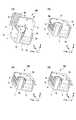
図1にインクジェットヘッド100の模式図を示す。本実施形態におけるインクジェットヘッド100は、インクを貯留する筐体としてのインクタンク1、記録素子基板2aが設けられた記録素子ユニット2、フレキシブル配線部材としてのフレキシブルケーブル4、及び電極部としての接点基板5を有している。インクタンク1の面1a(第一の面)には記録素子ユニット2が、面1bにはフレキシブルケーブル4(第二の面)が、面1c(第三の面)には接点基板5が、それぞれ取り付けられている。(Inkjet head)
FIG. 1 shows a schematic diagram of an
なお、X方向を記録素子基板2aの短手の部分に対して平行な方向、Y方向を記録素子基板2aの長手の部分に対して平行な方向、Z方向をインクタンク1の面1aに対して垂直な方向として、以下の説明で用いる。 The X direction is parallel to the short part of the
記録素子基板2aは、吐出口2bと、吐出口2bからインクを吐出するためのエネルギーを発生するヒーターなどのエネルギー発生素子(不図示)を有している。接点基板5には、記録装置側のコンタクト部202(図6(b))と接触することでインクジェットヘッド100の外部である記録装置200とインクジェットヘッド100を電気的に接続するコンタクト部3が設けられている。 The
フレキシブルケーブル4は、その一端に記録素子ユニット2が取り付けられ、反対側の一端には、接点基板5が取り付けられている。記録素子基板2aと接点基板5とは、フレキシブルケーブル4によって電気的に接続される。図3(a)に示すようにフレキシブルケーブル4はL字形状を有している。インクタンク1に固定された状態において、フレキシブルケーブル4は二箇所で屈曲されており、その屈曲した部分の屈曲線である稜線4aと4b(図1参照)とはその方向が互いに交差している。 The flexible cable 4 has a
フレキシブルケーブル4内の配線の数が多い場合、記録素子基板2aの短手の部分から配線を引き出すと、インクジェットヘッド100のX方向に関する寸法が大きくなってしまう。複数色のインクジェットヘッド100を並べる場合には、インクジェット記録装置200の幅が大きくなったりする恐れがある。そのため、図1に示したように、記録素子基板2aの長手の部分でフレキシブルケーブル4内の配線を接続する方が望ましい。 When the number of wirings in the flexible cable 4 is large, when the wiring is drawn out from the short part of the
電源や信号がインクジェット記録装置200からコンタクト部3、フレキシブルケーブル4を介してエネルギー発生素子に供給され、エネルギー発生素子を駆動することで、吐出口2bからインクを吐出させ、紙などの被記録媒体に記録を行う。
なお、本実施形態ではコンタクト部3は接点基板5に設けられているが、接点基板5を設置せずにフレキシブルケーブル4にコンタクト部3を配置する構成でもよい。この場合は、フレキシブルケーブル4のうち、コンタクト部3が設けられた部分を電極部とする。また、インクタンクを着脱可能であるタンクホルダに、記録素子ユニット2、フレキシブルケーブル4、接点基板5を取り付ける構成であってもよい。A power supply or a signal is supplied from the ink
In the present embodiment, the
(インクジェット記録装置)
インクジェットヘッド100が着脱可能に装着されるインクジェット記録装置200について、図6を用いて説明する。図6(a)は、インクジェット記録装置200の外観斜視図、(b)は、インクジェット記録装置200に設けられたキャリッジ201にインクジェットヘッド100を装着した状態を上面から見た模式図である。(Inkjet recording device)
An ink
複数色のインクジェットヘッド100を並べてインクジェット記録装置200に配置する際には、インクタンク1bの面にコンタクト部3を設けると、隣接するインクジェットヘッドの間にインクジェット記録装置200側のコンタクト部202を設けることになる。この場合、インクジェット記録装置200側のコンタクト部202を設けるためのスペース分、記録装置200の幅が大きくなってしまう。 When arranging the inkjet heads 100 of a plurality of colors side by side in the
そこで、上述したように本実施形態では、L字形状のフレキシブルケーブル4を記録素子基板2aの長手部分で配線を接続させ、フレキシブルケーブル4を二箇所で屈曲させることで、コンタクト部3をインクタンク1の面1cに設けている。このため、インクジェット記録装置200側のコンタクト部202をインクジェットヘッド100間に設けずに済むので、インクジェットヘッド100同士を近接させて配置することができる。 Therefore, as described above, in the present embodiment, the L-shaped flexible cable 4 is connected to the wiring at the longitudinal portion of the
(インクジェットヘッドの組み立て方法)
図2及び図3にインクジェットヘッド100の組み立て工程を示す。図2は、インクジェットヘッド100の組み立て工程のフロー図で、図3は、図2に対応する工程を説明するための図である。(Assembly method of inkjet head)
2 and 3 show an assembly process of the
インクジェットヘッド100の記録の品位は、記録素子ユニット2のインクタンク1に対する取り付けの位置精度に大きく依存する。そのため、インクジェットヘッド100を組み立てる際には、最初にインクタンク1に対して記録素子ユニット2の取り付け位置を決めて、インクタンク1の面1aに記録素子ユニット2を固定する(S1、図3(a))。このとき、フレキシブルケーブル4を予め記録素子ユニット2に接続していてもよいし、記録素子ユニット2をインクタンク1に固定した後にフレキシブルケーブル4を記録素子ユニット2に接続してもよい。 The recording quality of the
次に、フレキシブルケーブル4を屈曲させ(S2)、コンタクト部3がインクジェット記録装置200のコンタクト部202(図6)と接触するように、接点基板5をX及びZ方向に関するインクタンク1への固定位置で保持する(S3、図3(b))。このとき、インクタンク1の面1cに設けられたピン11(突出部)は、接点基板5に設けられた開口部5aに嵌まった状態となる。保持の状態では、接点基板5はインクタンク1に対して固定されておらず、フレキシブルケーブル4はたわむような寸法を持たせて設計されているので、接点基板5はY方向に関して移動可能となっている。なお、接点基板5の保持方法については後に説明する。フレキシブルケーブル4は予め屈曲させておいたものを用いても良いが、取り扱いやすさを考慮すると、屈曲させながら接点基板5を保持する方がより好ましい。また、図1に示したインクジェットヘッド100のようにコンタクト部3が設けられた接点基板5を用いる場合には、接点基板5とフレキシブルケーブル4の接続は、接点基板5の保持工程(S3)より前に行えばよい。 Next, the flexible cable 4 is bent (S2), and the
次に、図3(b)の状態を維持しながら、フレキシブルケーブルに設けられた開口9を、インクタンク1の面1bに設けられたピン12に嵌める。このピン12を熱溶着や超音波溶着等でかしめることにより、インクタンク1の面1bにフレキシブルケーブル4を固定する(S4、図3(c))。この際、フレキシブルケーブル4の、接点基板5が取り付けられている端部は、インクタンク1に固定されていないので、フレキシブルケーブル4のたわみを調整して、フレキシブルケーブル4のインクタンク1の外側方向へのたわみを所定量内に抑えることできる。 Next, while maintaining the state of FIG. 3B, the opening 9 provided in the flexible cable is fitted to the
最後に、接点基板5の開口部5aに嵌まったピン11を溶着することにより、接点基板5をインクタンク1に固定し、インクジェットヘッドの組み立てが完了する(図3(d))。 Finally, the
上述したように、フレキシブルケーブル4の一方の端部がインクタンク1に固定されていない状態で、フレキシブルケーブル4をインクタンク1に固定するので、フレキシブルケーブル4のたわみを調整することが可能である。これにより、フレキシブルケーブル4の折り曲げ線の方向が交差する場合であっても、フレキシブルケーブル4にねじれが生じ、内部の配線に負荷が生じたままインクタンク1に固定される恐れを低減することができる。 As described above, since the flexible cable 4 is fixed to the
なお、フレキシブルケーブル4のY方向に関するたわみは、コンタクト部3側の屈曲部付近、Z方向に関するたわみは記録素子ユニット2側の屈曲部付近で生じるように組み立てることが好ましい。また、インクタンク1の方向すなわち、インクジェットヘッド100の内側に向かってたわむように組み立てることが好ましい。このようにたわませることで、インクジェットヘッド100のインクジェット記録装置200に対する着脱時にフレキシブルケーブル4のたわみ部分が装置内部等にあたる恐れを低減することができる。 The flexible cable 4 is preferably assembled so that the deflection in the Y direction occurs near the bent portion on the
また、フレキシブルケーブル4をインクタンク1に固定した後に、接点基板5をインクタンク1に固定すると、コンタクト部3の取り付け位置がずれてしまい、インクジェット記録装置200との電気接続の信頼性が低下する恐れがある。 If the
そこで、上述したように本実施形態では、接点基板5をインクタンク1に対する取り付け位置で保持した状態で、フレキシブルケーブル4をインクタンク1に固定している。そのため、コンタクト部3のX方向及びZ方向に関するインクタンク1への取り付け位置精度を維持することができ、インクジェット記録装置200との電気接続信頼性が低下する恐れを抑制できる。 Therefore, as described above, in the present embodiment, the flexible cable 4 is fixed to the
なお、本実施形態では、接点基板5を保持する工程の前に、一端に記録素子ユニット2が設けられ、他端に接点基板5が設けられたフレキシブルケーブル4と、この記録素子ユニット2が固定されたインクタンク1と、を提供する工程があればよい。 In the present embodiment, before the step of holding the
なお、本実施形態では、フレキシブルケーブル4の記録素子ユニット2及び接点基板5が接続されていない部分は、インクタンク1の面1bに固定されているが、これが複数の面に固定されていてもよい。 In this embodiment, the portion of the flexible cable 4 where the
なお、本実施形態は、稜線4aと4bの方向が互いに交差する場合であったが、稜線4aと4bがねじれの位置にある場合にも、フレキシブルケーブル4内の配線にねじれが生じる恐れがある。すなわち、本実施形態は、屈曲部の稜線が平行でない場合において有効である。 In the present embodiment, the directions of the
また、本実施形態では、開口に嵌まったピンを溶着することでフレキシブルケーブル4や接点基板5をインクタンク1に固定していたが、固定方法はこれに限定されず、接着剤を用いて固定してもよい。 In this embodiment, the flexible cable 4 and the
次に、図4を用いてコンタクト部3が設けられた接点基板5をインクタンク1の所定位置に保持する方法およびその機構について説明する。 Next, a method and a mechanism for holding the
図4(a)は、治具15を用いて接点基板5を保持しているときの図1のA−A断面図である。図4(a)に示す方法では、インクタンク1の接点基板5が固定される面1cに設けられたピン11を、接点基板5に設けられた開口部5aに嵌めることで、コンタクト部3をX、Z方向に関するインクタンク1への取り付け位置に合わせた状態となる。この状態でピン11の先端部を冶具15で押さえることにより、コンタクト部3のX、Z方向に関するインクタンク1への取り付け位置で接点基板5を保持している。フレキシブルケーブル4はたわむような寸法で設計されているため、接点基板5の保持工程(S3)において、接点基板5はY方向に関して移動可能となる。 4A is a cross-sectional view taken along the line AA of FIG. 1 when the
図4(b)に、上記で説明した図4(a)の保持方法の変形例を示す。本変形例のインクジェットヘッド100においては、接点基板5に設けられた開口部5aの穴径がインクタンク1から突出したピン11の径よりも、コンタクト部3のインクタンク1に対する取り付け位置精度を許容可能な範囲内の寸法分だけ大きくなっている。ピン11を開口部5aに嵌めることで、コンタクト部3をX、Z方向に関するインクタンク1への取り付け位置に合わせた状態となる。このとき、ピン11の径よりも接点基板5に設けられた開口部5aの径の方が大きいので、接点基板5はコンタクト部3の取り付け位置精度を許容できる範囲内でX、Z方向に関して移動可能である。インクタンク1の接点基板5が固定される面1cには、インクタンク1から外側の方向へ接点基板5を押す弾性部材16が設けられている。この弾性部材16の弾性力が作用することで、接点基板5は、インクタンク1の面1cに対して傾斜し、接点基板5の開口部5aがピン11に引掛かった状態となる(図4(b))。これにより、コンタクト部3のX、Z方向に関するインクタンク1への取り付け位置において接点基板5が保持される。接点基板5の保持工程(S3)において、フレキシブルケーブル4はたわむような寸法で設計されているため、弾性部材16を押し戻すように、接点基板5はY方向に関して移動することが可能である。 FIG. 4B shows a modification of the holding method of FIG. 4A described above. In the
なお、図4(b)に示した構成では、インクタンク1に対して接点基板5がZ方向に関してインクタンク1の面1cに対して傾斜するように弾性部材16を設けていた。しかしX方向、すなわち図3(b)では紙面に対して接点基板5が傾斜するように弾性部材16を設けてもよい。X方向に関して傾斜する状態で接点基板5を保持すると、保持状態においてもフレキシブルケーブル4のねじれを抑制できるのでより好ましい。なお、弾性部材16は、バネやインクタンク1内のインクの有無を検知する電極を兼ねた部材であってもよい。 In the configuration shown in FIG. 4B, the
図5(a)は、フレキシブルケーブル4の一部の表面のフィルム層を透過し、内部の配線20を示す図である。図5(b)は、このフレキシブルケーブル4を用いたインクジェットヘッド100の斜視図である。フレキシブルケーブル4が固定されるインクタンク1の面1bから突出したピン12(図3(a))をフレキシブルケーブル4の開口10に嵌め、熱溶着等でピンを溶着してかしめることによりフレキシブルケーブル4をインクタンク1に固定する。 FIG. 5A is a diagram showing the
図5(a)に示すように、フレキシブルケーブル4を固定するための開口10(10a、10b)は、開口10の近傍に設けられた配線20の延びる方向(配線方向)に関して延びた長穴となっている。一方、配線方向に直角の方向に関する開口10の径は、インクタンク1から突出したピン12と同じもしくは若干大きい長さになっている。 As shown in FIG. 5A, the opening 10 (10a, 10b) for fixing the flexible cable 4 is an elongated hole extending in the extending direction (wiring direction) of the
これにより、フレキシブルケーブル4がインクタンク1に固定される際に、フレキシブルケーブル4は、配線方向に関する移動が可能で、配線方向に対して直角の方向に関する移動が規制されることになる。したがって、フレキシブルケーブル4がインクタンク1に固定する際に、配線方向に対して直角の方向のたわみの発生を抑え、配線方向にたわませてフレキシブルケーブル4を固定することができる。これにより、フレキシブルケーブル4のねじれが生じたままインクタンク1に固定される恐れを一層低減することができる。 Thereby, when the flexible cable 4 is fixed to the
なお、稜線4a及び4bで屈曲されるフレキシブルケーブル4の屈曲部においては、フレキシブルケーブル4内の配線20は一方向に延在するように設けられているため、屈曲部でたわみが生じても配線20のねじれは発生しにくい。一方で、屈曲部から遠い部分では、配線20がフレキシブルケーブル4の平面内で折れ曲がっているため、この配線20の折れ曲がり部20aにたわみが生じると、配線方向と異なる方向にたわむことにより、配線20のねじれが生じる恐れがある。そこで、フレキシブルケーブル4をインクタンク1の面1bに固定する際に、フレキシブルケーブル4内の配線20の平面内の折れ曲がり部20aに近い部分から先に固定し、フレキシブルケーブル4の屈曲部に近い部分は後で固定する方が望ましい。すなわち、図5(a)では、開口10aを先に固定し、開口10bを後で固定した方がよい。また、開口10aを設ける位置としては、配線20の折れ曲がり部20aの近傍に開口10を設けると、折れ曲がり部20aにおけるフレキシブルケーブル4のたわみを抑制できるのでより好ましい。 In addition, in the bending part of the flexible cable 4 bent by the
配線20の折れ曲がり部20aが直角に折れ曲がっていると、配線方向と直角の方向にたわむ恐れがあり、この場合に配線20にねじれが生じる恐れが高まる。そのため、図5(a)に示すように、直角に折れ曲がらないように配線20を設けたフレキシブルケーブル4を用いた方が望ましい。 If the
(比較例)
接点基板5をインクタンク1に固定した後にフレキシブルケーブル4を筐体に固定する場合、フレキシブルケーブル4の両端が固定されている状態でフレキシブルケーブル4を固定することになるので、フレキシブルケーブル4のたわみが大きくなる恐れがある。インクタンク1の外側方向へのたわみが大きいと、インクジェットヘッド100の記録装置200への着脱時にたわみ部分が記録装置200の内部にあたってしまう恐れが高まる。また、たわみの調節が困難であると、たわむ方向によってはフレキシブルケーブル内の配線にねじれが生じ、配線に負荷がかかったままフレキシブルケーブルが筐体に固定される恐れがある。(Comparative example)
When the flexible cable 4 is fixed to the housing after the
1 インクタンク(筐体)
2 記録素子ユニット
2a 記録素子基板
3 コンタクト部
4 フレキシブルケーブル(フレキシブル配線部材)
5 接点基板(電極部)
100 インクジェットヘッド(液体吐出ヘッド)1 Ink tank (housing)
2
5 Contact board (electrode part)
100 Inkjet head (liquid ejection head)
Claims (7)
Translated fromJapanese該素子基板と外部とを電気的に接続するための電極部と、
一端に前記素子基板が設けられ、他端に前記電極部が設けられ、前記素子基板と前記電極部とを電気的に接続するためのフレキシブル配線部材であって、屈曲された屈曲部を複数備え、複数の該屈曲部のうちの、少なくとも二つの前記屈曲部の夫々の稜線が平行でないフレキシブル配線部材と、
前記素子基板が固定される第一の面と、前記フレキシブル配線部材が固定される第二の面と、前記電極部が固定される第三の面と、を備えた筐体と、
を有する液体吐出ヘッドの組み立て方法であって、
前記素子基板及び前記電極部が設けられた前記フレキシブル配線部材と、前記素子基板が前記第一の面に固定された前記筐体と、を提供する工程と、
前記第三の面の、前記電極部が固定される位置において前記電極部を保持しながら、前記フレキシブル配線部材を前記第二の面に固定する工程と、
前記電極部を前記位置に固定する工程と、
をこの順に行うことを特徴とする液体吐出ヘッドの組み立て方法。An element substrate provided with an energy generating element for generating energy for discharging liquid;
An electrode part for electrically connecting the element substrate and the outside;
The element substrate is provided at one end and the electrode portion is provided at the other end, and is a flexible wiring member for electrically connecting the element substrate and the electrode portion, and includes a plurality of bent portions. A flexible wiring member in which each ridge line of at least two of the plurality of bent portions is not parallel; and
A housing having a first surface to which the element substrate is fixed, a second surface to which the flexible wiring member is fixed, and a third surface to which the electrode portion is fixed;
A method of assembling a liquid ejection head having
Providing the flexible wiring member provided with the element substrate and the electrode portion, and the housing in which the element substrate is fixed to the first surface;
Fixing the flexible wiring member to the second surface while holding the electrode portion at a position where the electrode portion is fixed on the third surface;
Fixing the electrode portion at the position;
A method for assembling the liquid discharge head, wherein the steps are performed in this order.
前記筐体は、前記第三の面に対して突出し、前記開口部に嵌まる突出部と、前記電極部に接し、前記第三の面に対して交差する方向に弾性力が作用する弾性部材と、を有し、
該弾性部材の弾性力により前記突出部を前記開口部に引っ掛けることで、前記位置において前記電極部を保持することを特徴とする請求項1または請求項2に記載の液体吐出ヘッドの組み立て方法。The electrode portion has an opening,
The casing protrudes with respect to the third surface, fits into the opening, and an elastic member that is in contact with the electrode portion and has an elastic force in a direction intersecting the third surface. And having
The method of assembling the liquid ejection head according to claim 1, wherein the electrode portion is held at the position by hooking the protruding portion onto the opening by the elastic force of the elastic member.
前記筐体は、前記第三の面に対して突出し、前記開口部に嵌まる突出部を有し、
前記突出部が前記開口部に嵌まった状態で、押さえ部材により前記突出部を押さえることで、前記位置において前記電極部を保持することを特徴とする請求項1または請求項2に記載の液体吐出ヘッドの組み立て方法。The electrode portion has an opening;
The housing protrudes with respect to the third surface and has a protrusion that fits into the opening,
3. The liquid according to claim 1, wherein the electrode portion is held at the position by pressing the protruding portion with a pressing member in a state where the protruding portion is fitted in the opening. 4. Assembly method of the discharge head.
前記フレキシブル配線部材を固定する工程において、前記折り曲がり部に近い位置から順に固定することを特徴とする請求項1乃至請求項5のいずれか一項に記載の液体吐出ヘッドの組み立て方法。The flexible wiring member has a wiring that electrically connects the element substrate and the electrode portion, and a bent portion in which the wiring is bent in a plane of the flexible wiring member,
6. The method of assembling a liquid discharge head according to claim 1, wherein in the step of fixing the flexible wiring member, the flexible wiring member is fixed in order from a position close to the bent portion.
前記フレキシブル配線部材は、前記素子基板と前記電極部とを電気的に接続する配線と、近傍に設けられる前記配線が延びる方向に延びた長穴である開口と、を有し
前記筐体は、前記第二の面に対して突出し、前記開口に嵌まる突出部を有し、
前記開口に嵌まった突出部が溶着されることで、前記フレキシブル配線部材は前記筐体に固定されていることを特徴とする液体吐出ヘッド。A liquid discharge head assembled by the method of assembling a liquid discharge head according to any one of claims 1 to 4,
The flexible wiring member includes a wiring that electrically connects the element substrate and the electrode portion, and an opening that is a long hole extending in a direction in which the wiring provided in the vicinity extends. Projecting with respect to the second surface and having a projecting portion that fits into the opening;
The liquid discharge head according to claim 1, wherein the flexible wiring member is fixed to the casing by welding a protruding portion fitted in the opening.
Priority Applications (2)
| Application Number | Priority Date | Filing Date | Title |
|---|---|---|---|
| JP2010140915AJP5627312B2 (en) | 2010-06-21 | 2010-06-21 | Liquid discharge head and method of assembling liquid discharge head |
| US13/112,902US8616688B2 (en) | 2010-06-21 | 2011-05-20 | Liquid discharge head and assembly method of liquid discharge head |
Applications Claiming Priority (1)
| Application Number | Priority Date | Filing Date | Title |
|---|---|---|---|
| JP2010140915AJP5627312B2 (en) | 2010-06-21 | 2010-06-21 | Liquid discharge head and method of assembling liquid discharge head |
Publications (2)
| Publication Number | Publication Date |
|---|---|
| JP2012000955Atrue JP2012000955A (en) | 2012-01-05 |
| JP5627312B2 JP5627312B2 (en) | 2014-11-19 |
Family
ID=45328260
Family Applications (1)
| Application Number | Title | Priority Date | Filing Date |
|---|---|---|---|
| JP2010140915AExpired - Fee RelatedJP5627312B2 (en) | 2010-06-21 | 2010-06-21 | Liquid discharge head and method of assembling liquid discharge head |
Country Status (2)
| Country | Link |
|---|---|
| US (1) | US8616688B2 (en) |
| JP (1) | JP5627312B2 (en) |
Cited By (3)
| Publication number | Priority date | Publication date | Assignee | Title |
|---|---|---|---|---|
| JP2015093452A (en)* | 2013-11-13 | 2015-05-18 | キヤノン株式会社 | Liquid discharge head and manufacturing method thereof |
| JP2017149108A (en)* | 2016-02-26 | 2017-08-31 | 京セラ株式会社 | Liquid ejection head and recording device using the same |
| JP2020163713A (en)* | 2019-03-29 | 2020-10-08 | ブラザー工業株式会社 | Liquid discharge device, liquid discharge head |
Families Citing this family (3)
| Publication number | Priority date | Publication date | Assignee | Title |
|---|---|---|---|---|
| JP6415859B2 (en)* | 2014-06-04 | 2018-10-31 | エスアイアイ・プリンテック株式会社 | Liquid ejecting head and liquid ejecting apparatus |
| CN109130489B (en)* | 2017-06-15 | 2021-12-07 | 精工爱普生株式会社 | Liquid ejecting head and liquid ejecting apparatus |
| CN214215199U (en)* | 2020-09-11 | 2021-09-17 | 珠海纳思达企业管理有限公司 | Ink cartridge with printhead |
Citations (3)
| Publication number | Priority date | Publication date | Assignee | Title |
|---|---|---|---|---|
| JPS60192676A (en)* | 1984-03-14 | 1985-10-01 | Canon Inc | Ink jet recorder |
| JP2000198191A (en)* | 1998-10-27 | 2000-07-18 | Canon Inc | Head holder, head assembly, head cartridge, ink jet recording apparatus, and method of manufacturing head assembly |
| JP2005343079A (en)* | 2004-06-04 | 2005-12-15 | Canon Inc | Recording head unit and ink jet recording apparatus |
Family Cites Families (1)
| Publication number | Priority date | Publication date | Assignee | Title |
|---|---|---|---|---|
| EP0999060B1 (en) | 1998-10-27 | 2005-04-20 | Canon Kabushiki Kaisha | Head holder, head assembly, head cartridge, ink jet recorder, and method for manufacturing head assembly |
- 2010
- 2010-06-21JPJP2010140915Apatent/JP5627312B2/ennot_activeExpired - Fee Related
- 2011
- 2011-05-20USUS13/112,902patent/US8616688B2/ennot_activeExpired - Fee Related
Patent Citations (3)
| Publication number | Priority date | Publication date | Assignee | Title |
|---|---|---|---|---|
| JPS60192676A (en)* | 1984-03-14 | 1985-10-01 | Canon Inc | Ink jet recorder |
| JP2000198191A (en)* | 1998-10-27 | 2000-07-18 | Canon Inc | Head holder, head assembly, head cartridge, ink jet recording apparatus, and method of manufacturing head assembly |
| JP2005343079A (en)* | 2004-06-04 | 2005-12-15 | Canon Inc | Recording head unit and ink jet recording apparatus |
Cited By (3)
| Publication number | Priority date | Publication date | Assignee | Title |
|---|---|---|---|---|
| JP2015093452A (en)* | 2013-11-13 | 2015-05-18 | キヤノン株式会社 | Liquid discharge head and manufacturing method thereof |
| JP2017149108A (en)* | 2016-02-26 | 2017-08-31 | 京セラ株式会社 | Liquid ejection head and recording device using the same |
| JP2020163713A (en)* | 2019-03-29 | 2020-10-08 | ブラザー工業株式会社 | Liquid discharge device, liquid discharge head |
Also Published As
| Publication number | Publication date |
|---|---|
| JP5627312B2 (en) | 2014-11-19 |
| US20110310161A1 (en) | 2011-12-22 |
| US8616688B2 (en) | 2013-12-31 |
Similar Documents
| Publication | Publication Date | Title |
|---|---|---|
| JP5627312B2 (en) | Liquid discharge head and method of assembling liquid discharge head | |
| JP6198578B2 (en) | Liquid discharge head and manufacturing method thereof | |
| CN107031192B (en) | Liquid consumption device and method of assembling the same | |
| EP2839960B1 (en) | Liquid ejecting head and liquid ejecting apparatus | |
| JP2010194899A (en) | Liquid jetting head unit and liquid jetting device | |
| KR20080113376A (en) | Liquid cartridge and circuit board | |
| JP6903873B2 (en) | Liquid discharge head | |
| US9174454B2 (en) | Liquid ejection head and liquid ejection apparatus | |
| JP6504889B2 (en) | Liquid discharge head and method of manufacturing liquid discharge head | |
| US6659595B2 (en) | Liquid jet recording head | |
| JP5096699B2 (en) | Connector holder unit, carriage, recording device, liquid ejecting device | |
| JP5433628B2 (en) | Circuit board and inkjet head manufacturing method | |
| JP5018899B2 (en) | Liquid jet head | |
| US9233536B2 (en) | Liquid ejection head, liquid ejection apparatus, and method of manufacturing liquid ejection head | |
| JP6119173B2 (en) | Liquid ejecting head module and liquid ejecting apparatus | |
| JP4737430B2 (en) | Carriage device, recording device, liquid ejecting device | |
| JP2004358912A (en) | Head cartridge | |
| JP2016175188A (en) | Liquid jet head and liquid jet device | |
| JP2016185709A (en) | Liquid ejecting head module and liquid ejecting apparatus | |
| JP2023055114A (en) | Liquid ejection head and manufacturing method therefor | |
| US20100103223A1 (en) | Flexible printed circuit board and liquid discharge head including the same | |
| JP2003039670A (en) | Inkjet print head | |
| JP4661228B2 (en) | Droplet discharge head and droplet discharge apparatus | |
| JP5246537B2 (en) | Optical element / electronic component mounting board | |
| US20240316929A1 (en) | Liquid Ejecting Head And Liquid Ejecting Apparatus |
Legal Events
| Date | Code | Title | Description |
|---|---|---|---|
| A621 | Written request for application examination | Free format text:JAPANESE INTERMEDIATE CODE: A621 Effective date:20130621 | |
| A977 | Report on retrieval | Free format text:JAPANESE INTERMEDIATE CODE: A971007 Effective date:20140122 | |
| A131 | Notification of reasons for refusal | Free format text:JAPANESE INTERMEDIATE CODE: A131 Effective date:20140204 | |
| A521 | Request for written amendment filed | Free format text:JAPANESE INTERMEDIATE CODE: A523 Effective date:20140407 | |
| TRDD | Decision of grant or rejection written | ||
| A01 | Written decision to grant a patent or to grant a registration (utility model) | Free format text:JAPANESE INTERMEDIATE CODE: A01 Effective date:20140902 | |
| A61 | First payment of annual fees (during grant procedure) | Free format text:JAPANESE INTERMEDIATE CODE: A61 Effective date:20140930 | |
| LAPS | Cancellation because of no payment of annual fees |