JP2011527768A - + Axisymmetric polarized beam - Google Patents
+ Axisymmetric polarized beamDownload PDFInfo
- Publication number
- JP2011527768A JP2011527768AJP2011517423AJP2011517423AJP2011527768AJP 2011527768 AJP2011527768 AJP 2011527768AJP 2011517423 AJP2011517423 AJP 2011517423AJP 2011517423 AJP2011517423 AJP 2011517423AJP 2011527768 AJP2011527768 AJP 2011527768A
- Authority
- JP
- Japan
- Prior art keywords
- mode
- polarization
- hybrid
- azimuth
- fiber
- Prior art date
- Legal status (The legal status is an assumption and is not a legal conclusion. Google has not performed a legal analysis and makes no representation as to the accuracy of the status listed.)
- Granted
Links
Images


Classifications
- G—PHYSICS
- G02—OPTICS
- G02B—OPTICAL ELEMENTS, SYSTEMS OR APPARATUS
- G02B6/00—Light guides; Structural details of arrangements comprising light guides and other optical elements, e.g. couplings
- G02B6/02—Optical fibres with cladding with or without a coating
- G02B6/024—Optical fibres with cladding with or without a coating with polarisation maintaining properties
- C—CHEMISTRY; METALLURGY
- C03—GLASS; MINERAL OR SLAG WOOL
- C03B—MANUFACTURE, SHAPING, OR SUPPLEMENTARY PROCESSES
- C03B2203/00—Fibre product details, e.g. structure, shape
- C03B2203/10—Internal structure or shape details
- C—CHEMISTRY; METALLURGY
- C03—GLASS; MINERAL OR SLAG WOOL
- C03B—MANUFACTURE, SHAPING, OR SUPPLEMENTARY PROCESSES
- C03B2203/00—Fibre product details, e.g. structure, shape
- C03B2203/10—Internal structure or shape details
- C03B2203/18—Axial perturbations, e.g. in refractive index or composition
- C03B2203/19—Alternating positive/negative spins or twists
- C—CHEMISTRY; METALLURGY
- C03—GLASS; MINERAL OR SLAG WOOL
- C03B—MANUFACTURE, SHAPING, OR SUPPLEMENTARY PROCESSES
- C03B2203/00—Fibre product details, e.g. structure, shape
- C03B2203/32—Eccentric core or cladding
- C—CHEMISTRY; METALLURGY
- C03—GLASS; MINERAL OR SLAG WOOL
- C03B—MANUFACTURE, SHAPING, OR SUPPLEMENTARY PROCESSES
- C03B2205/00—Fibre drawing or extruding details
- C03B2205/06—Rotating the fibre fibre about its longitudinal axis
- G—PHYSICS
- G02—OPTICS
- G02B—OPTICAL ELEMENTS, SYSTEMS OR APPARATUS
- G02B6/00—Light guides; Structural details of arrangements comprising light guides and other optical elements, e.g. couplings
- G02B6/10—Light guides; Structural details of arrangements comprising light guides and other optical elements, e.g. couplings of the optical waveguide type
- G02B6/14—Mode converters
Landscapes
- Physics & Mathematics (AREA)
- General Physics & Mathematics (AREA)
- Optics & Photonics (AREA)
- Polarising Elements (AREA)
- Optical Couplings Of Light Guides (AREA)
- Optical Fibers, Optical Fiber Cores, And Optical Fiber Bundles (AREA)
Abstract
Translated fromJapaneseDescription
Translated fromJapanese本出願は、2008年7月10日に出願された米国仮特許出願第61/079641号及び2008年11月26日に出願された米国仮特許出願第61/118097号の優先権の恩典を主張する。 This application claims the benefit of priority of US Provisional Patent Application No. 61/079641 filed on July 10, 2008 and US Provisional Patent Application No. 61/118097 filed on November 26, 2008. To do.
本発明は、撚り光導波路デバイスを用いて入力直線偏極ガウシアンビームから発生される、ハイブリッドアジマス(方位角方向)偏極ビーム及びハイブリッドラジアル(径方向)偏極ビームをラジアル偏極ビーム及びアジマス偏極ビームとともに含む、HARPモードと称される、軸対称偏極光ビームに関する。 The present invention relates to a hybrid azimuth (azimuth direction) polarized beam and a hybrid radial (radial direction) polarized beam generated from an input linearly polarized Gaussian beam using a twisted optical waveguide device. It relates to an axisymmetric polarized light beam, referred to as a HARP mode, which is included with the polar beam.
光渦を有する光ビームは多くの重要な用途に望ましい。そのような用途には、例えば、光学像形成、リソグラフィ、帯電粒子加速、材料処理、高効率レーザ切断、高効率レーザ溶接及び計測学がある。さらに、ラジアル偏極光ビーム及びアジマス偏極光ビームにより、回折限界をこえるビームの集束が可能になると同時に、定常縦電場及び定常縦磁場の発生が可能になる。 Light beams with optical vortices are desirable for many important applications. Such applications include, for example, optical imaging, lithography, charged particle acceleration, material processing, high efficiency laser cutting, high efficiency laser welding and metrology. Further, the radial polarized light beam and the azimuth polarized light beam enable focusing of the beam exceeding the diffraction limit, and at the same time, generation of a steady longitudinal electric field and a steady longitudinal magnetic field.
軸対称ベクトルビームと称される、ラジアル偏極光ビーム及び/またはアジマス偏極光ビームは、例えば、キャビティ内偏極操作、コンピュータ生成ホログラム、少数モード光ファイバへのオフセット入力及び高次モード光ファイバ励起を含む、いくつかの異なる方法を用いて発生させることができる。光トラップのような用途に対し、ラジアル偏極ビームは周囲媒体をトラップすることができ、アジマス偏極ビームは誘電率が周囲媒体より低い粒子をトラップするようにはたらく。ラジアル偏極とアジマス偏極の切換えは、例えば2枚の1/2波長板を用いて、行うことができる。 Radial and / or azimuth polarized light beams, referred to as axisymmetric vector beams, can be used, for example, for intracavity polarization manipulation, computer generated holograms, offset input to a few mode optical fiber, and higher order mode optical fiber excitation. It can be generated using several different methods, including: For applications such as optical traps, the radially polarized beam can trap the surrounding medium, and the azimuth polarized beam acts to trap particles with a lower dielectric constant than the surrounding medium. Switching between radial polarization and azimuth polarization can be performed using, for example, two half-wave plates.
これらの方法はベクトルビームを発生するために考案されたが、これらの方法では少数モードファイバを、非対称位相板、1/2波長板及び偏極コントローラのような、多くの微小光学コンポーネントとともに使用する必要があるため、複雑である。例えば、初めに位相板を用いて入力ガウシアンビームを非対称ビームに変換し、次いで軸対称偏極モードへの変換を可能にするために多くの偏極コンポーネントを用いることになろう。 Although these methods were devised to generate vector beams, these methods use minority mode fibers with many micro-optical components such as asymmetric phase plates, half-wave plates and polarization controllers. It is complicated because it is necessary. For example, one would use a number of polarization components to initially convert the input Gaussian beam to an asymmetric beam using a phase plate and then to convert to an axisymmetric polarization mode.
光ファイバを撚り合わせると光ファイバの第1の空間モード、すなわちLP01モードの2つの直線偏極モードの間の結合をおこさせ得ることは周知である。例えば、非特許文献1,特許文献1及び非特許文献2を見よ。そのような撚り合わせの手法及び技術は、長距離光ファイバ伝送線路における偏極モード分散を低減する目的のため、十分に研究されている。It is well known that twisting an optical fiber can cause a coupling between two linear polarization modes of the first spatial mode of the optical fiber, namely the LP01 mode. For example, see Non-Patent Document 1, Patent Document 1 and Non-Patent Document 2. Such twisting techniques and techniques have been well studied for the purpose of reducing polarization mode dispersion in long haul optical fiber transmission lines.
本発明は、発明者等がハイブリッドアジマス偏極モードと称し、ハイブリッドラジアル偏極モードとも称する偏極モードを含む、軸対称偏極光を入力直線偏極ガウシアンビームから発生させるための方法を説明する。ハイブリッドアジマス偏極モードはアジマス偏極モードとHE21モードの組合せである。ハイブリッドラジアル偏極モードもラジアル偏極モードとHE21モードの組合せである。変換は撚り少数モード光導波路デバイス内でおこる。導波路は、屈折率分布が渦−ベクトル偏極モードの直線偏極LP11重ね合わせの伝搬を可能にするに適切な、撚りファイバ導波路である。さらに、コアは若干楕円形とすることができ、コアの中心はデバイスの幾何学的中心から若干ずれている。線引きプロセス中のファイバの撚り合わせにより、これらの非対称性は撚りの周期でデバイス長に沿って回転させられる。センチメートル程度ないしさらに短い周期の重ね合わせでデバイスを撚り合わせることで、光が入力基本モードからLP11モードに結合され、これは渦−ベクトルモードの重ね合わせである。これらのモードは、HE21モード、ラジアルモード及びアジマスモードを含む。The present invention describes a method for generating axially symmetric polarized light from an input linearly polarized Gaussian beam, including a polarization mode that the inventors refer to as a hybrid azimuth polarization mode, also referred to as a hybrid radial polarization mode. The hybrid azimuth polarization mode is a combination of the azimuth polarization mode and the HE21 mode. The hybrid radial polarization mode is also a combination of the radial polarization mode and the HE21 mode. The conversion occurs in the twisted minority mode optical waveguide device. The waveguide is a twisted fiber waveguide suitable for allowing propagation of a linearly polarized LP11 overlay with a refractive index profile in a vortex-vector polarization mode. Furthermore, the core can be slightly elliptical, with the core center slightly offset from the geometric center of the device. Due to the twisting of the fiber during the drawing process, these asymmetries are rotated along the device length with a twist period. By twisting the device in centimeters moderate to shorter periods of superposition, the light is coupled from the input fundamental mode to the LP11 mode, which is the vortex - is a superposition of the vector mode. These modes include HE21 mode, radial mode and azimuth mode.
ジー・ボルプ(G. Volpe),ディー・ペトロフ(D. Petrov),「ラゲール-ガウシアンビームによって励起された少数モード光ファイバによる軸対称ベクトルビームの発生(Generation Of Cylindrical Vector Beams With Few-Mode Fibers Excited By Laguerre-Gaussian Beams)」,Opt. Commun.,2004年,第237巻,p.89〜95、及びその他の論文に説明されているように、ステップインデックス型ファイバ内部を伝搬するモードの偏極特性と軸対称ベクトルビームの間の相似性を利用することによって軸対称ベクトルビームを発生させることができる。少数モードファイバは基本モードLP01(HE11)だけでなく、さらに二次モードLP11(TE01,TM01及びHE21)もサポートする。TE01モード及びTM01モードの横電場はそれぞれ、アジマス偏極電場及びラジアル偏極電場を与え、ハイブリッド電場モードのHE21モードはハイブリッド構造を有する。しかし、ファイバ断面内のモードパワー分布はLP01モードとLP11モードとで異なる。LP01に対して、パワーはファイバの軸を囲む小領域に集中する。対照的に、LP11に対して、例えばファイバの入力においてガウシアンビームの代わりに一次ラゲール−ガウシアンLG10ビームを用いると、パワーはドーナツ形状で分布する。G. Volpe, D. Petrov, “Generation Of Cylindrical Vector Beams With Few-Mode Fibers Excited By Laguerre-Gaussian Beams), Opt. Commun., 2004, Vol. 237, pp. 89-95, and other papers, mode polarization propagating inside a step index fiber. An axisymmetric vector beam can be generated by exploiting the similarity between the properties and the axisymmetric vector beam. The minority mode fiber supports not only the fundamental mode LP01 (HE11 ) but also the secondary modes LP11 (TE01 , TM01 and HE21 ). The transverse electric fields of the TE01 mode and the TM01 mode give an azimuth polarized electric field and a radial polarized electric field, respectively, and the HE21 mode of the hybrid electric field mode has a hybrid structure. However, the mode power distribution in the fiber cross section differs between the LP01 mode and the LP11 mode. For LP01 , the power is concentrated in a small area surrounding the fiber axis. In contrast, for LP11 , for example, using a primary Laguerre-Gaussian LG10 beam instead of a Gaussian beam at the fiber input, the power is distributed in a donut shape.
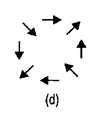
4つのLP11モード、すなわち、TE01モード,TM01モード,HE21偶モード及びHE21奇モードの横電場は:
として与えられ、ここでF(r)はラジアル関数であり、
及び
は単位ベクトルである。これらの様々なモードの偏極パターンが図1に示される。これらのモードに対しては3つの伝搬常数、すなわち、偶HE21モード及び奇HE21モードに対するβHE,TE01モードに対するβTE及びTM01モードに対するβTM,があるから、全電場偏極状態はファイバに沿って変化する。Is a unit vector. The polarization patterns for these various modes are shown in FIG. Three propagation constants for these modes, i.e., betaHE for evenHE 21 mode and oddHE 21 mode, betaTM against betaTE andTM 01 mode forTE 01 mode, because there is total electric field polarized state Varies along the fiber.
上に示したように、ラジアル偏極ビームまたはアジマス偏極ビームの偏極状態に対する一般式はそれぞれ、式[1]:
で与えられ、ここで、φはビーム周りの角位置を表し、a,bはある角度において円偏極状態または楕円偏極状態を可能にする係数である。a=b=1の場合の、これらの2つの偏極状態がそれぞれ図2(a)及び2(b)に示される。図2(c)は:
に対して、a=1,b=iとした場合の、偏極状態を示す。On the other hand, the polarization state when a = 1 and b = i is shown.
これは、発明者等が本明細書でハイブリッドアジマス偏極(HAP)状態として説明し、発明者等がハイブリッドラジアル偏極(HRP)状態として説明する直交状態を有する、本発明にしたがう新しい偏極状態である。HAPモードはφ=0,π/2,π,3π/2においてアジマス偏極と同様の偏極を有し、φ=π/4,3π/4,5π/4及び7π/4において円偏極と同様の偏極を有する。 This is a new polarization according to the present invention that has an orthogonal state that we describe herein as a hybrid azimuth polarization (HAP) state and which we describe as a hybrid radial polarization (HRP) state. State. HAP mode has the same polarization as azimuth polarization at φ = 0, π / 2, π, 3π / 2, and circular polarization at φ = π / 4, 3π / 4, 5π / 4, and 7π / 4 Have the same polarization.
HRPモードはφ=0,π/2,π,3π/2においてラジアル偏極と同様の偏極を有し、φ=π/4,3π/4,5π/4及び7π/4において円偏極と同様の偏極を有する。HAPモード及びHRPモードは発明者等がHARPモードと称している分類を形成する。 HRP mode has the same polarization as radial polarization at φ = 0, π / 2, π, 3π / 2, and circular polarization at φ = π / 4, 3π / 4, 5π / 4, and 7π / 4 Have the same polarization. The HAP mode and the HRP mode form a classification that we have called the HARP mode.
ハイブリッドアジマス偏極は横電場TE01モードとハイブリッド電場(偶)HE21モードの重ね合わせとして書くことができる。TE01モードは図1(a)及び2(b)に示されるアジマス偏極モードと同じモードである。対処的に、HE21モードはそれ自体ハイブリッドモードであり、図1(d)に示される。TE01モードをHE21モードと与えられた位相差(i)で:
のように組み合わせれば、HAP状態が生じる。HE21モードの前の因子‘i’は、最終偏極における円偏極成分の原因となる、2つの偏光状態の間のπの位相差を表す。If combined in this way, a HAP state occurs. The factor 'i' before the HE21 mode represents the π phase difference between the two polarization states that causes the circular polarization component in the final polarization.
ハイブリッドラジアル偏極(HRP)モードはHAP偏極モードに直交し、TM01モードと奇HE21モードの重ね合わせ:
である。It is.
HAPモード及びHRPモードの線運動量及び角運動量は、エル・アレン(L. Allen),エム・ジェイ・パジェット(M. J. Padgett),エム・ベイビカー(M. Babiker),Progress in Optics XXIX,1999年,p.291〜372の方法にしたがって計算することができる。ここでHAPモードを、HRPモードに関して同様の言明がなされ得ることを念頭において、詳細に考察する。上式[1]からわかるように、偏極状態εはφの関数であり、また単位ベクトル:
及び
を含むことが示される。r及びφとして書き換えれば、HAP状態の表出の原因になる項である、定数a及びbを消去することができるであろう。ベクトルポテンシャルが:
の形をとるとし、ここで、
であり、
はビーム周りの方位角位置であり、
であるとすれば、ローレンツゲージ[10]から計算される電場及び磁場は、式[3]:
及び、式[4]:
である。It is.
これらの場を用いて時間平均線運動量:
を計算すれば、式[5]:
が得られる。Is obtained.
式[5]から、HAP状態の角運動量密度が、式[6]:
と計算される。Is calculated.
倍角の公式を用いれば、
である。これを円偏極光ビームについて計算された角運動量と比較すれば、円偏極光の旋進性に依存して±1の値を有し、また直線偏極光については0の値を有していた、光子のスピン角運動量として知られる‘σ’が、今では空間においてsin2φで変化する値をとることがわかる。このφ依存性は、局所的に、角運動量が、φ=0における0から、φ=π/4における:
になり、次いでφ=π/2における0になり,次いでφ=3π/4における:
になり、以下同様に変化することを意味する。図1(c)において円偏極があれば必ず、角運動量は:
である。ビームにわたって積分することで全角運動量を計算すれば、式[7]:
が得られ、式[7]におけるjzのφに関する0から2πまでの積分は0である。よって、ハイブリッド偏極に対する角運動量密度の空間変化が非ゼロであっても、全角運動量は事実上、ゼロである。これは、純ラジアル偏極モードまたは純アジマス偏極モードのいずれに対しても角運動量密度はゼロ、すなわち:
及び
であるから、純ラジアル偏極光または純アジマス偏極光の場合の角運動量と異なる。Therefore, it is different from the angular momentum in the case of pure radial polarized light or pure azimuth polarized light.
実験及びデータ
LP01空間モードの1つの偏極モードから別の偏極モードへの結合を生じさせるためには、ファイバの撚りレートがビート長より十分に短いことが必要である。ビート長はファイバコアの楕円率の逆数に関係する。ビート長は、コアが若干楕円形のファイバの2つの直線偏極モードの伝搬定数または実効屈折率の差にも関係する。Experimental and Data LP01 It is necessary for the twist rate of the fiber to be sufficiently shorter than the beat length in order to cause coupling from one polarization mode to another polarization mode. The beat length is related to the reciprocal of the ellipticity of the fiber core. The beat length is also related to the difference in propagation constant or effective refractive index of the two linearly polarized modes of the fiber having a slightly elliptical core.
ここで、LP11モードはHE21モードの、またラジアル偏極モード及びアジマス偏極モードの重ね合わせである。これらのモードは全て相異なる伝搬定数を有する。例えば、ヴァッサロ(Vassallo)著,「光導波路(Optical Waveguide Concepts)」,1991年,エルスビア(Elsevier)を見よ。これらのモードの伝搬定数または屈折率は全て互いに若干異なる。ファイバの撚り合わせはこれらの全てのモードの間で結合を生じさせ得る。Here, the LP11 mode is a superposition of the HE21 mode and the radial polarization mode and the azimuth polarization mode. All of these modes have different propagation constants. See, for example, “Optical Waveguide Concepts” by Vassallo, 1991, Elsevier. All of these modes have slightly different propagation constants or refractive indices. Fiber twisting can cause coupling between all these modes.
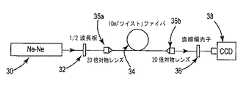
HAP状態を有する渦ビームを発生するための実験構成が図3に示される。波長が632.8nmの縦(直線)偏極He-Ne(ヘリウム-ネオン)レーザ30が1/2波長板32を通過して、所望の方位に回転させることができる直線偏極ガウシアンビームになる。直線偏極ガウシアンビームは次いで、ビームを撚りファイバ34のコア上に集束させるはたらきをする20倍の顕微鏡対物レンズ35aを通して、撚りファイバ34に結合される。ファイバからの出力は第2の20倍顕微鏡対物レンズ35bによって減結合され、対物レンズ35bは出力モードを拡大するためにはたらく。ビームは次いで出力偏極状態を定めるための検光子としてはたらく直線偏光子36を通過する。強度分布がモノクロCCDカメラ38上に記録される。 An experimental setup for generating a vortex beam having a HAP state is shown in FIG. A longitudinally (linear) polarized He-Ne (helium-neon)
縦偏極He-Neレーザ30が直線偏極ガウシアンビームの発生源として説明されるが、いかなる直線偏極ガウシアンビーム発生源も用いられ得ることが当業者には明らかである。しかし、ファイバに入力されると、光がLP11モードとして伝搬するような発生源が好ましい。図3に示される実験構成において、楕円コアファイバ34は作成時に20ターン/mのレートで撚り合わされる。しかし、ファイバ34の撚りレートは変換をおこさせたいファイバの楕円率及びファイバ長に依存して変わり得る。例えば、軸対称ファイバは理論的にはさらに低いレートで撚ることができるが、レートは10ターン/mより高いことが好ましい。しかし、楕円コアファイバを用いると、さらに高い撚りレートで同じモード結合効果を生じさせ得るであろう。Although longitudinally polarized He-
さらに、この実験に用いた撚りファイバ34の長さはほぼ10mである。しかし、モード変換をおこさせるに十分にファイバが長ければ、ファイバ長は数cmから所望のいかなる長さにも変わり得る。与えられた楕円率に対し、ファイバ長を短くしていくにつれて、撚りファイバの撚りレートを高めていく必要があろう。さらに、図3の実験構成はカットオフ波長が740nmのファイバを示している。しかし、LP11モードの発生のために必要なことは、ファイバを伝搬する光の波長よりカットオフ波長が長いことだけである。波長が632.8nmのレーザ30を用いていたから、カットオフ波長が740nmの撚りファイバは許容できた。しかし、HE31モードより高次のHEモードの伝搬を可能にするには、カットオフ波長が長すぎないことが好ましい。図3に示される実験構成によれば、撚りファイバ34は1%のコアΔ及び数μmのコア径を有し、この結果として、適切なカットオフ波長が得られている。今説明したように、様々なコアΔとコア径の組合せを有するファイバを、適切なカットオフ波長が達成されるならば、用いることができる。Further, the length of the twisted
図3に示される実験構成において、撚りファイバの撚りコアは若干楕円形である。軸対称コアを用いることができるが、楕円の方位は回転するから、楕円形であることによって、異なる偏極モードへの、また異なる偏極モードからの、優れた結合が可能になる。撚りファイバのコアの楕円率は5%より大きい離心率を有することが好ましい。実験に用いた撚りファイバはさらに、ファイバクラッドの幾何学的中心から若干ずらされたコア中心を有する。このずれのため、対称ガウシアンモードから非対称ラゲール-ガウシアンモードへの空間モード分布の変化が可能になる。コア中心はファイバの幾何学的中心から少なくともコア径の10%はずらされることが好ましい。 In the experimental configuration shown in FIG. 3, the twisted core of the twisted fiber is slightly elliptical. Although an axisymmetric core can be used, the orientation of the ellipse rotates, so that the elliptical shape allows excellent coupling to and from different polarization modes. The ellipticity of the core of the twisted fiber preferably has an eccentricity greater than 5%. The twisted fiber used in the experiment also has a core center that is slightly offset from the geometric center of the fiber cladding. This shift allows the spatial mode distribution to change from a symmetric Gaussian mode to an asymmetric Laguerre-Gaussian mode. The core center is preferably offset from the geometric center of the fiber by at least 10% of the core diameter.
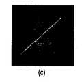
直線偏極光が撚りファイバ34に入力して直線検光子36を通過したときの代表的な出力が図4に示される。図は検光子の偏光角がそれぞれ(b)0°,(c)45°及び(d)90°に設定されたときの撚りファイバ34からのコリメートされた出力のベクトル状態を示す。検光子が0°または90°に設定されたときの強度パターンは一次エルミート-ガウシアンモードに類似し、検光子が45°に設定されたときの強度分布は一次ラゲール-ガウシアンモードに類似する。この撚りファイバ34は実効的に、ゼロ次モードを一次モードに変換する、モードコンバータとしてはたらく。入射偏極光の方位は撚りファイバ34からのHAP出力に影響しない。 A typical output when linearly polarized light enters the twisted
LP11モード間の光の変換に必要な撚りレートを計算するためには、初めに、LP11のベクトルモード、すなわち、HE21モード、TMモード及びTEモードについての、LP11モード[4]への偏極補正を計算する必要がある。これらのベクトルモードの内の2つの間の差に等価なレートで撚りレートが続けば、光は、その2つのベクトルモードの一方から他方に、迅速かつ完全に転換するであろう。
撚りファイバ34の出力状態の撚りレート依存性が表1に示される。全般的に、本発明には軸対称である撚りファイバ導波路デバイスが包含されるであろうが、コア中心がデバイスの幾何学的中心から若干ずらされている、若干楕円形の導波路が用いられることが好ましい。そのような構成では、ファイバ線引きプロセス中にファイバを撚り合わせることで、非対称性をファイバ長に沿って撚り周波数で回転させる。したがって、撚られていない、すなわち撚りレートが0ターン/mの、同じカットオフ周波数及び屈折率をもつファイバに光を結合させても渦は見られない。代わりに、直線偏極であるエルミート-ガウシアンモードが見られる。図5を参照すれば、無撚りファイバの出力は図5(b)または(d)のようなHGモード構造を有する。ファイバへの結合のアライメントに依存して、出力はHG10モードまたはHG01モードになる。図5(b)〜(d)は、 (b)0°,(c)45°及び(d)90°に設定されている直線偏光子を光が通過した後の偏極状態を簡略に示す。Table 1 shows the twist rate dependence of the output state of the twisted
しかし、撚りレートが10ターン/mのファイバに光が結合されると、出力は、光渦を有し、偏極が全くの直線偏極ではなく、全くのハイブリッドアジマス偏極でもない、渦とHGモードの間の混合のように見える、軸対称ベクトルモードへの変換の兆候を示し始める。 However, when light is coupled into a fiber with a twist rate of 10 turns / m, the output has an optical vortex and the polarization is not a linear polarization at all, nor is it a hybrid azimuth polarization, It begins to show signs of conversion to axisymmetric vector mode, which looks like a blend between HG modes.
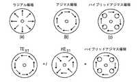
撚りレートが20ターン/mのファイバに光が結合されると、出力は、図5(a)に簡略な線図で、また図4(a)の偏光子出力図で示されるような、HEモードへの完全な変換を示す。図示されるように、撚りファイバの出力は直線偏極状態及び円偏極状態を含むベクトル重ね合わせ状態にある光渦である。したがって、HAP状態が形成されていることが示される。 When light is coupled into a fiber with a twist rate of 20 turns / m, the output is HE, as shown in the simplified diagram in FIG. 5 (a) and the polarizer output diagram in FIG. 4 (a). Indicates complete conversion to mode. As shown in the figure, the output of the twisted fiber is an optical vortex in a vector superposition state including a linearly polarized state and a circularly polarized state. Therefore, it is shown that the HAP state is formed.
図4及び5に示され、説明される軸対称ベクトルは、ビームプロファイルを90°まわる毎に円偏極状態が現れるハイブリッドアジマス偏極の実験観測結果である。次に図6を参照すれば、方位が0°または90°に定められた1/4波長板を挿入することによって、ハイブリッドアジマス偏極ビームを純アジマス偏極状態に変換することができる。これは円偏極領域の方位が円偏極の旋進性に依存して45°または135°に定められた直線偏極への変換であり、直線偏極状態には影響しないであろう。このビームはさらに、図6に示されるように、方位が45°に定められた1/2波長板をビーム路に挿入することによって純ラジアル偏極モードに変換することができる。 The axisymmetric vectors shown and described in FIGS. 4 and 5 are experimental observations of hybrid azimuth polarization where a circularly polarized state appears every 90 degrees around the beam profile. Next, referring to FIG. 6, the hybrid azimuth polarized beam can be converted into a pure azimuth polarized state by inserting a quarter wave plate whose azimuth is set to 0 ° or 90 °. This is a conversion to linear polarization in which the orientation of the circularly polarized region is set to 45 ° or 135 ° depending on the rotation of the circularly polarized region and will not affect the linearly polarized state. Further, as shown in FIG. 6, this beam can be converted into a pure radial polarization mode by inserting a half-wave plate having an azimuth of 45 ° into the beam path.
さらに、線引きプロセス中のファイバ撚り合わせは、光の、アジマス偏極モードへの直接結合よりもハイブリッドアジマス偏極モードへの結合を生じさせ得る。これは、ハイブリッドがHE21モードとアジマスモードの組合せであり、一方のモードだけより両モードによる占有の方がおこり易くなるための結果である。In addition, fiber twisting during the drawing process can cause the coupling of light into a hybrid azimuth polarization mode rather than direct coupling into the azimuth polarization mode. This is because the hybrid is a combination of the HE21 mode and the azimuth mode, and the occupation by both modes is more likely to occur than only one mode.
上述は本発明の実施形態例を含む。本発明を説明する目的のためにコンポーネントまたは方法の全ての組合せを説明することはもちろん不可能であるが、当業者であれば、本発明の多くの別の組合せ及び置換が可能であることを認めるであろう。したがって、本発明は、添付される特許請求項の精神及び範囲内に入るような、別形、改変及び変形の全てを包含するとされる。 What has been described above includes examples of the present invention. It is of course impossible to describe all combinations of components or methods for the purpose of illustrating the invention, but those skilled in the art will recognize that many other combinations and substitutions of the invention are possible. I will admit. Accordingly, the present invention is intended to embrace all such alterations, modifications and variations that fall within the spirit and scope of the appended claims.
30 レーザ
32 1/2波長板
34 撚りファイバ
35a,35b 20倍顕微鏡対物レンズ
36 直線偏光子
38 モノクロCCDカメラ30
Claims (10)
Translated fromJapanesea.入力ビームとして直線偏極ガウシアンビームを発生させる工程、及び
b.コアを有する撚りファイバによって前記入力ビームを結合させる工程、
を含み、
前記撚りファイバが10ターン/mより高いレートで撚り合わされる、
ことを特徴とする方法。In a method for generating a hybrid azimuth polarization mode or a hybrid radial polarization mode,
a. Generating a linearly polarized Gaussian beam as an input beam; and b. Combining the input beam with a twisted fiber having a core;
Including
The twisted fiber is twisted at a rate higher than 10 turns / m,
A method characterized by that.
a.直線偏極入力ビームの伝搬を可能にする屈折率分布、及び
b.軸対称であるが前記ファイバの幾何学的中心から中心が若干ずらされているコア、を有する撚りファイバ導波路を備え、
c.前記撚りファイバ導波路が、線引きプロセス中に、前記ファイバの前記直線偏極モード間の結合を生じさせるに十分な撚りレートで撚り合わされる、
ことを特徴とするモード変換器。In a mode converter for converting a linearly polarized Gaussian beam into a hybrid azimuth polarized beam or a hybrid radial polarized beam, a twisted fiber waveguide comprising:
a. A refractive index profile that allows propagation of a linearly polarized input beam; and b. A twisted fiber waveguide having an axially symmetric core that is slightly offset from the geometric center of the fiber,
c. The twisted fiber waveguide is twisted at a twist rate sufficient to cause coupling between the linearly polarized modes of the fiber during the drawing process;
A mode converter characterized by that.
a.入力ビームとして直線偏極ガウシアンビームを発生させる工程、
b.ハイブリッドアジマス偏極モードを生じさせるに十分なレートで撚り合わされた、コアを有する撚りファイバによって前記入力ビームを結合させる工程、
c.アジマス偏極モードを生じさせるために、前記ハイブリッドアジマス偏極モードに1/4波長板を通過させる工程、及び
d.ラジアル偏極モードを生じさせるために、前記アジマス偏極モードに1/2波長板を通過させる工程、
を含むことを特徴とする方法。In a method for generating a radial polarization mode,
a. Generating a linearly polarized Gaussian beam as an input beam;
b. Combining the input beam with a twisted fiber having a core twisted at a rate sufficient to produce a hybrid azimuth polarization mode;
c. Passing a quarter wave plate through the hybrid azimuth polarization mode to produce an azimuth polarization mode; and d. Passing a half-wave plate through the azimuth polarization mode to generate a radial polarization mode;
A method comprising the steps of:
a.入力ビームとして直線偏極ガウシアンビームを発生させる工程、
b.ハイブリッドラジアル偏極モードを生じさせるに十分なレートで撚り合わされた、コアを有する撚りファイバによって前記入力ビームを結合させる工程、及び
c.アジマス偏極モードを得るために、前記ハイブリッドラジアル偏極モードに1/4波長板を通過させる工程、
を含むことを特徴とする方法。In a method for generating an azimuth polarization mode,
a. Generating a linearly polarized Gaussian beam as an input beam;
b. Combining the input beam with a twisted fiber having a core twisted at a rate sufficient to produce a hybrid radial polarization mode; and c. Passing a quarter wave plate through the hybrid radial polarization mode to obtain an azimuth polarization mode;
A method comprising the steps of:
Applications Claiming Priority (5)
| Application Number | Priority Date | Filing Date | Title |
|---|---|---|---|
| US7964108P | 2008-07-10 | 2008-07-10 | |
| US61/079,641 | 2008-07-10 | ||
| US11809708P | 2008-11-26 | 2008-11-26 | |
| US61/118,097 | 2008-11-26 | ||
| PCT/US2009/004013WO2010005579A1 (en) | 2008-07-10 | 2009-07-09 | +cylindrical polarization beams |
Publications (3)
| Publication Number | Publication Date |
|---|---|
| JP2011527768Atrue JP2011527768A (en) | 2011-11-04 |
| JP2011527768A5 JP2011527768A5 (en) | 2012-08-23 |
| JP5518059B2 JP5518059B2 (en) | 2014-06-11 |
Family
ID=41507358
Family Applications (1)
| Application Number | Title | Priority Date | Filing Date |
|---|---|---|---|
| JP2011517423AExpired - Fee RelatedJP5518059B2 (en) | 2008-07-10 | 2009-07-09 | + Axisymmetric polarized beam |
Country Status (5)
| Country | Link |
|---|---|
| US (1) | US8111957B2 (en) |
| EP (1) | EP2324381B1 (en) |
| JP (1) | JP5518059B2 (en) |
| CN (1) | CN102132177A (en) |
| WO (1) | WO2010005579A1 (en) |
Cited By (2)
| Publication number | Priority date | Publication date | Assignee | Title |
|---|---|---|---|---|
| CN103149640A (en)* | 2013-03-06 | 2013-06-12 | 上海理工大学 | Device and method for generating axisymmetric polarized light |
| JP2020126111A (en)* | 2019-02-01 | 2020-08-20 | 公立大学法人大阪 | Mode controller |
Families Citing this family (19)
| Publication number | Priority date | Publication date | Assignee | Title |
|---|---|---|---|---|
| US8437588B2 (en)* | 2010-04-06 | 2013-05-07 | University Of Hyderabad | System and method for generating an optical vector vortex beam having two lobes |
| US20130177273A1 (en)* | 2010-07-12 | 2013-07-11 | Research Foundation of CUNY on behalf of City College | Cylindrical Vector Beam Generation From A Multicore Optical Fiber |
| US9300398B2 (en) | 2012-01-09 | 2016-03-29 | Attochron, Llc | USPL-FSO lasercom point-to-point and point-to-multipoint optical wireless communication |
| CN104698541B (en)* | 2015-03-09 | 2017-11-21 | 哈尔滨工程大学 | A kind of radial polarisation light generating device |
| PL226041B1 (en) | 2015-03-25 | 2017-06-30 | Inst Tech Materiałów Elektronicznych | Photonic optical waveguide for transmitting radially polarized light beam and method for manufacturing such an optical waveguide |
| CN105207720B (en)* | 2015-08-24 | 2017-10-27 | 北京邮电大学 | Light signal modulating method and device, optical signal demodulation method and device |
| CN105137624B (en)* | 2015-09-25 | 2019-02-22 | 西北工业大学 | Apparatus and method for generating cylindrical vector beams in optical fibers using electrically controlled tunable gratings |
| US10168501B2 (en)* | 2016-05-27 | 2019-01-01 | Nxgen Partners Ip, Llc | System and method for transmissions using eliptical core fibers |
| US10429584B2 (en) | 2016-11-22 | 2019-10-01 | Lumentum Operations Llc | Rotary optical beam generator |
| US10656334B2 (en) | 2016-11-22 | 2020-05-19 | Lumentum Operations Llc | Rotary optical beam generator |
| US11347069B2 (en) | 2016-11-22 | 2022-05-31 | Lumentum Operations Llc | Rotary optical beam generator |
| US10690855B2 (en) | 2016-11-22 | 2020-06-23 | Lumentum Operations Llc | Tapered non-concentric core fibers |
| CN107978960B (en)* | 2017-12-15 | 2023-11-17 | 中国科学技术大学 | Debugging-free column vector fiber laser |
| US10733729B2 (en)* | 2018-09-17 | 2020-08-04 | Research Foundation Of The City University Of New York | Method for imaging biological tissue using polarized Majorana photons |
| DE102018127891B3 (en) | 2018-11-08 | 2020-04-23 | MAX-PLANCK-Gesellschaft zur Förderung der Wissenschaften e.V. | Method and device for forming a light intensity distribution with a central intensity minimum and scanning fluorescence light microscope with such a device |
| CN109581680A (en)* | 2019-01-09 | 2019-04-05 | 邯郸学院 | Three rank linear polarization orbital angular momentum generator of all -fiber |
| US11614398B2 (en) | 2019-09-17 | 2023-03-28 | Robert Alfano | Method for imaging biological tissue using polarized majorana vector and complex vortex photons from laser and supercontinuum light sources |
| CN113777794B (en)* | 2021-08-27 | 2024-04-30 | 哈尔滨工程大学 | Perfect circular polarization separator based on magneto-electric coupling |
| CN114355499B (en)* | 2022-02-24 | 2023-11-17 | 哈尔滨工程大学 | A method for generating transverse spin angular momentum from unpolarized light |
Citations (4)
| Publication number | Priority date | Publication date | Assignee | Title |
|---|---|---|---|---|
| JPH06171970A (en)* | 1992-08-03 | 1994-06-21 | American Teleph & Telegr Co <Att> | Optical fiber, its production and light communication system |
| JPH11508221A (en)* | 1996-01-22 | 1999-07-21 | コーニング インコーポレイテッド | Optical fiber with spin modulation to reduce polarization mode dispersion and method and apparatus for manufacturing the same |
| JP2000515653A (en)* | 1997-05-22 | 2000-11-21 | ドナム システム インク | Optical fiber polarization controller |
| JP2002525647A (en)* | 1998-09-17 | 2002-08-13 | コーニング インコーポレイテッド | Circular polarization fiber for optical circuit |
Family Cites Families (7)
| Publication number | Priority date | Publication date | Assignee | Title |
|---|---|---|---|---|
| GB1292363A (en)* | 1970-04-28 | 1972-10-11 | Coal Industry Patents Ltd | Electrical connector |
| US4697876A (en)* | 1983-02-25 | 1987-10-06 | Andrew Corporation | Fiber-optic rotation sensor |
| US4915468A (en)* | 1987-02-20 | 1990-04-10 | The Board Of Trustees Of The Leland Stanford Junior University | Apparatus using two-mode optical waveguide with non-circular core |
| US6020584A (en)* | 1997-02-14 | 2000-02-01 | Corning Incorporated | Method of measuring the polarization mode dispersion of an optical waveguide device |
| US6778747B1 (en) | 1998-09-09 | 2004-08-17 | Corning Incorporated | Radially varying and azimuthally asymmetric optical waveguide fiber |
| US6937325B2 (en)* | 2003-01-30 | 2005-08-30 | Fitel U.S.A. Corporation | Method and apparatus for measuring eccentricity in a optical fiber |
| US7778498B2 (en)* | 2008-02-12 | 2010-08-17 | Ofs Fitel Llc | Systems and techniques for generating cylindrical vector beams |
- 2009
- 2009-07-07USUS12/498,591patent/US8111957B2/ennot_activeExpired - Fee Related
- 2009-07-09JPJP2011517423Apatent/JP5518059B2/ennot_activeExpired - Fee Related
- 2009-07-09EPEP09794827.7Apatent/EP2324381B1/ennot_activeNot-in-force
- 2009-07-09WOPCT/US2009/004013patent/WO2010005579A1/enactiveApplication Filing
- 2009-07-09CNCN2009801337927Apatent/CN102132177A/enactivePending
Patent Citations (4)
| Publication number | Priority date | Publication date | Assignee | Title |
|---|---|---|---|---|
| JPH06171970A (en)* | 1992-08-03 | 1994-06-21 | American Teleph & Telegr Co <Att> | Optical fiber, its production and light communication system |
| JPH11508221A (en)* | 1996-01-22 | 1999-07-21 | コーニング インコーポレイテッド | Optical fiber with spin modulation to reduce polarization mode dispersion and method and apparatus for manufacturing the same |
| JP2000515653A (en)* | 1997-05-22 | 2000-11-21 | ドナム システム インク | Optical fiber polarization controller |
| JP2002525647A (en)* | 1998-09-17 | 2002-08-13 | コーニング インコーポレイテッド | Circular polarization fiber for optical circuit |
Non-Patent Citations (2)
| Title |
|---|
| JPN6013029015; G.Volpe, D.Petrov: 'Generation of cylindrical vector beams with few-mode fibers excited by Laguerre-Gaussian beams' Optics Communications 327, 2004, 89-95, Elsevier* |
| JPN6013029018; C N Alexeyev, A V Volyar and M A Yavorsky: 'Intensely twisted elliptic optical fibers maintaining propagation of a single optical vortex' Journal of Optics:Pure and Applied Optics , 20061008, L5-L9, Institute of Physics Publishing* |
Cited By (3)
| Publication number | Priority date | Publication date | Assignee | Title |
|---|---|---|---|---|
| CN103149640A (en)* | 2013-03-06 | 2013-06-12 | 上海理工大学 | Device and method for generating axisymmetric polarized light |
| JP2020126111A (en)* | 2019-02-01 | 2020-08-20 | 公立大学法人大阪 | Mode controller |
| JP7290854B2 (en) | 2019-02-01 | 2023-06-14 | 公立大学法人大阪 | mode controller |
Also Published As
| Publication number | Publication date |
|---|---|
| CN102132177A (en) | 2011-07-20 |
| US20100142890A1 (en) | 2010-06-10 |
| WO2010005579A1 (en) | 2010-01-14 |
| US8111957B2 (en) | 2012-02-07 |
| JP5518059B2 (en) | 2014-06-11 |
| EP2324381A4 (en) | 2013-09-18 |
| EP2324381B1 (en) | 2017-11-08 |
| EP2324381A1 (en) | 2011-05-25 |
Similar Documents
| Publication | Publication Date | Title |
|---|---|---|
| JP5518059B2 (en) | + Axisymmetric polarized beam | |
| Mao et al. | Generation of polarization and phase singular beams in fibers and fiber lasers | |
| Eismann et al. | Exciting a chiral dipole moment in an achiral nanostructure | |
| Zhan | Cylindrical vector beams: from mathematical concepts to applications | |
| Volpe et al. | Generation of cylindrical vector beams with few-mode fibers excited by Laguerre–Gaussian beams | |
| Grosjean et al. | An all-fiber device for generating radially and other polarized light beams | |
| Zhan | Vectorial optical fields: Fundamentals and applications | |
| Shu et al. | Polarization evolution of vector beams generated by q-plates | |
| Huo et al. | Observation of spatiotemporal optical vortices enabled by symmetry-breaking slanted nanograting | |
| Grosjean et al. | A versatile and stable device allowing the efficient generation of beams with radial, azimuthal or hybrid polarizations | |
| Moh et al. | Direct noninterference cylindrical vector beam generation applied in the femtosecond regime | |
| Schimpf et al. | Radially polarized Bessel-Gauss beams: decentered Gaussian beam analysis and experimental verification | |
| Droop et al. | Shaping light in 3d space by counter-propagation | |
| Hari Krishna et al. | Analyzing characteristics of spiral vector beams generated by mixing of orthogonal LP11 modes in a few-mode optical fiber | |
| Krishna et al. | Generation of inhomogeneously polarized vector vortex modes in few mode optical fiber | |
| Alinezhad et al. | Optimal condition for optical trapping of large particles: tuning the laser power and numerical aperture of the objective | |
| Ruan et al. | Free space vortex light by diffraction of a Bessel beam from optical fiber | |
| Ploss et al. | Generation and subwavelength focusing of longitudinal magnetic fields in a metallized fiber tip | |
| Harrison et al. | High-energy generation of arbitrary cylindrical vector vortex beams using a modified Mach–Zehnder interferometer | |
| Lombard et al. | Polarization control of non-diffractive helical optical beams through subwavelength metallic apertures | |
| Karpeev et al. | Forming vortex Bessel beam for optical communication at the wavelength of 1530 nm | |
| Wang et al. | High-purity large mode field super-stable vortex beam generator | |
| Dong et al. | A generation method of tunable cylindrical vector ring beam | |
| Murugesan et al. | Generating multiple focal structures with circularly polarized double ring shaped beam and axial birefringence | |
| Luo et al. | A special double-cladding fiber for generating dark hollow beam |
Legal Events
| Date | Code | Title | Description |
|---|---|---|---|
| A521 | Request for written amendment filed | Free format text:JAPANESE INTERMEDIATE CODE: A523 Effective date:20120706 | |
| A621 | Written request for application examination | Free format text:JAPANESE INTERMEDIATE CODE: A621 Effective date:20120706 | |
| A977 | Report on retrieval | Free format text:JAPANESE INTERMEDIATE CODE: A971007 Effective date:20130527 | |
| A131 | Notification of reasons for refusal | Free format text:JAPANESE INTERMEDIATE CODE: A131 Effective date:20130618 | |
| A521 | Request for written amendment filed | Free format text:JAPANESE INTERMEDIATE CODE: A523 Effective date:20130912 | |
| TRDD | Decision of grant or rejection written | ||
| A01 | Written decision to grant a patent or to grant a registration (utility model) | Free format text:JAPANESE INTERMEDIATE CODE: A01 Effective date:20140304 | |
| A61 | First payment of annual fees (during grant procedure) | Free format text:JAPANESE INTERMEDIATE CODE: A61 Effective date:20140401 | |
| R150 | Certificate of patent or registration of utility model | Ref document number:5518059 Country of ref document:JP Free format text:JAPANESE INTERMEDIATE CODE: R150 | |
| R250 | Receipt of annual fees | Free format text:JAPANESE INTERMEDIATE CODE: R250 | |
| LAPS | Cancellation because of no payment of annual fees |