JP2011526821A - Device for treating breathing disorders at night - Google Patents
Device for treating breathing disorders at nightDownload PDFInfo
- Publication number
- JP2011526821A JP2011526821AJP2011516929AJP2011516929AJP2011526821AJP 2011526821 AJP2011526821 AJP 2011526821AJP 2011516929 AJP2011516929 AJP 2011516929AJP 2011516929 AJP2011516929 AJP 2011516929AJP 2011526821 AJP2011526821 AJP 2011526821A
- Authority
- JP
- Japan
- Prior art keywords
- jaw
- connecting element
- contact
- adjusting
- screw
- Prior art date
- Legal status (The legal status is an assumption and is not a legal conclusion. Google has not performed a legal analysis and makes no representation as to the accuracy of the status listed.)
- Pending
Links
- 230000029058respiratory gaseous exchangeEffects0.000titledescription2
- 230000008878couplingEffects0.000claimsabstractdescription30
- 238000010168coupling processMethods0.000claimsabstractdescription30
- 238000005859coupling reactionMethods0.000claimsabstractdescription30
- 208000023504respiratory system diseaseDiseases0.000claimsabstractdescription4
- 230000000295complement effectEffects0.000claimsdescription5
- 210000005179oral vestibuleAnatomy0.000claims1
- 230000004048modificationEffects0.000description11
- 238000012986modificationMethods0.000description11
- 210000002455dental archAnatomy0.000description4
- 206010041235SnoringDiseases0.000description1
- 208000030303breathing problemsDiseases0.000description1
- 208000037265diseases, disorders, signs and symptomsDiseases0.000description1
- 208000035475disorderDiseases0.000description1
- 238000006073displacement reactionMethods0.000description1
- 210000001847jawAnatomy0.000description1
- 238000005259measurementMethods0.000description1
- 210000004237neck muscleAnatomy0.000description1
- 229940037201orisDrugs0.000description1
- 210000003254palateAnatomy0.000description1
- 230000000284resting effectEffects0.000description1
- 201000002859sleep apneaDiseases0.000description1
- 208000019116sleep diseaseDiseases0.000description1
- 230000001720vestibularEffects0.000description1
Images


Classifications
- A—HUMAN NECESSITIES
- A61—MEDICAL OR VETERINARY SCIENCE; HYGIENE
- A61F—FILTERS IMPLANTABLE INTO BLOOD VESSELS; PROSTHESES; DEVICES PROVIDING PATENCY TO, OR PREVENTING COLLAPSING OF, TUBULAR STRUCTURES OF THE BODY, e.g. STENTS; ORTHOPAEDIC, NURSING OR CONTRACEPTIVE DEVICES; FOMENTATION; TREATMENT OR PROTECTION OF EYES OR EARS; BANDAGES, DRESSINGS OR ABSORBENT PADS; FIRST-AID KITS
- A61F5/00—Orthopaedic methods or devices for non-surgical treatment of bones or joints; Nursing devices ; Anti-rape devices
- A61F5/56—Devices for preventing snoring
- A61F5/566—Intra-oral devices
Landscapes
- Health & Medical Sciences (AREA)
- Otolaryngology (AREA)
- Pulmonology (AREA)
- Nursing (AREA)
- Orthopedic Medicine & Surgery (AREA)
- Engineering & Computer Science (AREA)
- Biomedical Technology (AREA)
- Heart & Thoracic Surgery (AREA)
- Vascular Medicine (AREA)
- Life Sciences & Earth Sciences (AREA)
- Animal Behavior & Ethology (AREA)
- General Health & Medical Sciences (AREA)
- Public Health (AREA)
- Veterinary Medicine (AREA)
- Orthopedics, Nursing, And Contraception (AREA)
- Respiratory Apparatuses And Protective Means (AREA)
Abstract
Translated fromJapaneseDescription
Translated fromJapanese この発明は、呼吸障害を治療するための装置に関する。当該装置は、
・下顎に取付け可能な下方部分と、上顎に取付け可能な上方部分とを含み、これらの下方部分および上方部分は、少なくとも奥歯の付近に位置しており、当該装置はさらに、
・下方部分を奥歯付近で上方部分に連結するための左および右の連結手段を含み、左および右の連結手段の各々は、上方部分に接続された上方連結要素と、下方部分に接続された下方連結要素とを含む。左および右の連結手段は、上顎に対して下顎を前方に移動させるよう適合される。The present invention relates to a device for treating respiratory disorders. The device is
A lower part attachable to the lower jaw and an upper part attachable to the upper jaw, the lower part and the upper part being located at least near the back teeth, the device further comprising:
-Including left and right coupling means for coupling the lower part to the upper part near the back teeth, each of the left and right coupling means being connected to an upper coupling element connected to the upper part and to the lower part A lower connecting element. The left and right coupling means are adapted to move the lower jaw forward relative to the upper jaw.
夜間の呼吸障害は一般に公知の問題であり、たとえば、いびき、睡眠時無呼吸症候群、または他の睡眠障害を引き起こす可能性がある。人の睡眠時には、舌の後部が後方に滑っていく傾向があり、このため、咽頭の気道が完全にまたは部分的に閉ざされてしまう恐れがある。このような呼吸障害を解決するための装置が公知であり、このような装置は口内に配置することができ、下顎を上顎に対してさらに前方に位置させるものである。これにより、頸筋が強制的に引っ張られた状態となるため、舌が前方に移動し、気道が開かれる。 Nighttime breathing problems are generally known problems and can cause, for example, snoring, sleep apnea syndrome, or other sleep disorders. During human sleep, the back of the tongue tends to slip backwards, which can cause the pharyngeal airways to be completely or partially closed. Devices for resolving such breathing disorders are known and such devices can be placed in the mouth and position the lower jaw further forward relative to the upper jaw. As a result, the neck muscles are forcibly pulled, so that the tongue moves forward and the airway is opened.
口内に配置可能な上記装置が一般に公知であり、1990年代以来公知であったプリアンブルに記載の実施例を含む幾つかのさまざまな実施例において見出すことができる。公知の実施例には、開口/閉口時に過度に自由な移動を引き起こしてしまうという欠点もある。 Such devices that can be placed in the mouth are generally known and can be found in several different embodiments, including those described in the preamble known since the 1990s. The known embodiment also has the disadvantage of causing excessively free movement when opening / closing.
US2007/0283967およびWO2007/113465はともに、連結手段が下方の歯列弓と上方の歯列弓との間に設けられている口腔装置を開示している。このような装置では、舌を安静位に置くことができず、制御の可能性が極めて制限されてしまう。 US 2007/0283967 and WO 2007/113465 both disclose oral appliances in which the connecting means are provided between the lower dental arch and the upper dental arch. With such a device, the tongue cannot be placed in a resting position, and the control possibilities are extremely limited.
本発明は、請求項1のプリアンブルに記載の装置を提供することを目的とする。当該装置は、使いやすく、快適に装着できるものであり、上顎に対する下顎の自由な移動を制限しつつ精密に調節することを可能にする。 The object of the present invention is to provide a device according to the preamble of claim 1. The device is easy to use and comfortable to wear and allows precise adjustment while limiting the free movement of the lower jaw relative to the upper jaw.
本発明が上述の目的に関して傑出しているのは次の点によるものである。すなわち、上方連結要素が、下方連結要素の接触面との協働用の止め具を備えており、これにより、下顎および上顎が互いの方に移動した場合に、接触面が止め具に当たったときにさらなる閉口が防止される。左および右ならびに上方および下方の連結要素はさらに、口内に配置された装置の位置において口腔前庭(vestibulum oris)に位置するように、すなわち、連結要素が歯と左および右のそれぞれの頬との間に位置するように、上方部分および下方部分にそれぞれ接続される。 The present invention stands out for the above-mentioned purpose because of the following points. That is, the upper connecting element is provided with a stop for cooperation with the contact surface of the lower connecting element, so that the contact surface hits the stop when the lower jaw and the upper jaw move towards each other Sometimes further closure is prevented. The left and right and upper and lower connecting elements are further located in the vestibulum oris at the position of the device placed in the mouth, i.e. the connecting elements are between the teeth and the left and right cheeks respectively. Connected to the upper part and the lower part, respectively, so as to be located between them.
このようにして、上顎に対する下顎の自由な移動も、鉛直方向に、すなわち、下顎または上顎の面に対して実質的に垂直な方向に、制限される。 In this way, the free movement of the lower jaw relative to the upper jaw is also restricted in the vertical direction, ie in a direction substantially perpendicular to the surface of the lower jaw or the upper jaw.
有利な実施例に従うと、上方連結要素および下方連結要素のうち少なくとも1つの連結要素は、下顎と上顎との間に調整可能な最小限の距離を得るために、下顎に対する止め具/接触面の鉛直位置を調整するための鉛直調整手段を備える。 According to an advantageous embodiment, at least one of the upper connecting element and the lower connecting element has a stop / contact surface of the lower jaw in order to obtain a minimum adjustable distance between the lower jaw and the upper jaw. A vertical adjustment means for adjusting the vertical position is provided.
本発明の局面に従うと、少なくとも1つの連結要素は、上方部分または下方部分にそれぞれ接続された接触部分および基部を含む。この場合、鉛直調整手段は、基部に対して接触部分の鉛直位置を調整する目的で、接触部分と基部との間に設けられている。接触部分と基部との間の距離を広げることにより、(その上に接触面または止め具が位置している)接触部分が、上方部分または下方部分からさらに延在することとなり、自由な移動がさらに制限されてしまう。 According to an aspect of the invention, the at least one coupling element includes a contact portion and a base connected to the upper portion or the lower portion, respectively. In this case, the vertical adjustment means is provided between the contact portion and the base portion for the purpose of adjusting the vertical position of the contact portion with respect to the base portion. By increasing the distance between the contact portion and the base, the contact portion (on which the contact surface or stop is located) will extend further from the upper or lower portion, allowing free movement. It will be further limited.
実現可能な実施例に従うと、調整手段は、基部に対して接触部分を上方/下方に調整するためのダブルスクリュー(double screw)を備えた実質的に鉛直な調整ねじを有する。この調整ねじは、一方の外端においては、接触部分における第1のねじ穴と協働し、他方の外端においては、基部における第2のねじ穴と協働する。ここで、調整ねじの回転により、第1のねじ穴と第2のねじ穴との間の距離が変化する。さらに展開された実施例に従うと、調整ねじは、実質的にその中心に環状フランジを備え、当該環状フランジは、径方向の開口部を有しており、当該開口部にロッドが嵌まり込んでいる。これは、ロッドを回転させることによって調整ねじを回転させることを目的としたものである。このようにして、鉛直距離を簡便な態様で調整することができる。基部と接触部分との間における入れ子式に(telescopically)作動する管を鉛直調整ねじの両側に設けて、装置の安定性を向上させることもできる。 According to a possible embodiment, the adjusting means comprises a substantially vertical adjusting screw with a double screw for adjusting the contact part up / down relative to the base. This adjusting screw cooperates with a first screw hole in the contact portion at one outer end and with a second screw hole at the base at the other outer end. Here, the distance between the first screw hole and the second screw hole changes due to the rotation of the adjusting screw. According to a further developed embodiment, the adjusting screw has an annular flange substantially at its center, the annular flange having a radial opening, with a rod fitted into the opening. Yes. This is intended to rotate the adjusting screw by rotating the rod. In this way, the vertical distance can be adjusted in a simple manner. Tubes that telescopically operate between the base and the contact portion may be provided on both sides of the vertical adjustment screw to improve the stability of the device.
本発明の別の局面に従うと、上方連結要素および下方連結要素のうち少なくとも1つの連結要素は、下方部分または上方部分に接続される固定部分と、下方部分または上方部分に対して実質的に平行である当該固定部分に対して変位可能な部分とを含む。「下方部分または上方部分に対して平行な」とは、装置が口内に配置された場合に下歯または上歯それぞれの面に対して実質的に平行になっていることを意味するものと理解されるべきである。このようにして、下顎が上顎に対して前方に移動するのを同様に調整することができる。 According to another aspect of the invention, at least one of the upper connecting element and the lower connecting element includes a fixed part connected to the lower part or the upper part and a substantially parallel to the lower part or the upper part. And a portion displaceable with respect to the fixed portion. “Parallel to the lower or upper part” is understood to mean substantially parallel to the respective surface of the lower or upper tooth when the device is placed in the mouth. It should be. In this way, it can be similarly adjusted that the lower jaw moves forward relative to the upper jaw.
実現可能な実施例に従うと、変位可能な部分は、水平変位および鉛直変位がともに可能となるように接触部分を備えている。水平とは、変位可能な部分が上方連結要素または下方連結要素に位置しているかどうかに応じて、装置が口内に配置された際に下歯または上歯それぞれの面に対して実質的に平行になっていることを意味するものと理解されるべきである。鉛直とは、下顎または上顎それぞれの面に対して実質的に垂直になっていることを意味するものと理解されるべきである。 According to a feasible embodiment, the displaceable part comprises a contact part so that both horizontal and vertical displacement are possible. Horizontal means substantially parallel to the surface of the lower or upper teeth when the device is placed in the mouth, depending on whether the displaceable part is located on the upper or lower connecting element. Should be understood to mean By vertical is to be understood as meaning substantially perpendicular to the respective face of the lower or upper jaw.
本発明のさらに別の局面に従うと、各々の上方連結要素は、前歯の方に向けられた凹面または凸面を備えた実質的に鉛直な部分を含み、各々の下方連結要素は、実質的に相補形の表面を有している。このため、上方連結要素が下方連結要素に係合可能となり、下顎の後方への動きが防止される。このようにして、下方連結要素に対する上方連結要素の鉛直移動がさらに案内かつ制限される一方で、上顎が下顎に対して横方向に移動することが可能となる。これについては、以下にさらに説明するとおりである。 According to yet another aspect of the invention, each upper coupling element includes a substantially vertical portion with a concave or convex surface directed toward the front teeth, and each lower coupling element is substantially complementary. Has a shaped surface. For this reason, the upper connecting element can be engaged with the lower connecting element, and the backward movement of the lower jaw is prevented. In this way, the vertical movement of the upper coupling element relative to the lower coupling element is further guided and restricted while the upper jaw can move laterally with respect to the lower jaw. This is as further described below.
本発明の好ましい実施例に従うと、上方連結要素および下方連結要素は、上顎に配置された上方部分に対する下顎に配置された下方部分の制限された横方向へのまたは横向きの動き、すなわち、歯の面の、奥歯に対する実質的に垂直な動き、が可能となるように設計されている。横方向への自由な動きが制限されていることにより、調整の精度について深刻な結果をもたらすことなく、装着時の快適さがさらに高められる。実現可能な実施例に従うと、下方連結要素は、口内に配置された装置の位置においては上方部分から横方向に離れて位置している。 According to a preferred embodiment of the invention, the upper and lower coupling elements are limited in lateral or lateral movement of the lower part arranged in the lower jaw with respect to the upper part arranged in the upper jaw, i.e. of the teeth It is designed to allow movement of the surface substantially perpendicular to the back teeth. The limited free movement in the lateral direction further increases the comfort in wearing without causing serious consequences for the accuracy of the adjustment. According to a possible embodiment, the lower connecting element is located laterally away from the upper part at the position of the device arranged in the mouth.
他の特徴および利点が、添付の図面に関連付けられたいくつかの非限定的な具体的実施例の説明から明らかになるだろう。 Other features and advantages will become apparent from the description of several non-limiting specific embodiments that are associated with the accompanying drawings.
さまざまな実施例の図面においては、同等の構成要素は、同じ参照符号で示されており、参照符号には変形例ごとに100が追加されている。 In the drawings of the various embodiments, equivalent components are indicated with the same reference numerals, and 100 is added to the reference numerals for each variation.
図1、図3(A)および図3(B)ならびに図4は、呼吸障害を治療するための口腔装置1の好ましい実施例を示す。この装置1は、下顎に取付け可能であり成形部分2の形をした下方部分と、上顎に取付け可能であり成形部分3の形をした上方部分とを備える。当業者であれば、下方部分および上方部分が異なる態様で具体化可能であることを理解するだろう。また、部分という語は、たとえば口蓋プレートおよび可撓性のある咬合阻止器(bite-block)を備えたブレースを意味するものと理解される。唯一の要件として、下方部分および上方部分を少なくとも奥歯の付近に位置させて、これにより、そこで連結要素を下方部分2/上方部分3に取付け可能にすることが挙げられる。 1, 3A and 3B and FIG. 4 show a preferred embodiment of an oral device 1 for treating respiratory disorders. This device 1 comprises a lower part that can be attached to the lower jaw and in the form of a molded part 2 and an upper part that can be attached to the upper jaw and in the form of a molded part 3. One skilled in the art will appreciate that the lower and upper portions can be embodied in different ways. The term part is also understood to mean a brace with, for example, a palate plate and a flexible bite-block. The only requirement is that the lower part and the upper part are located at least in the vicinity of the back teeth, so that the connecting element can be attached to the lower part 2 / upper part 3 there.
装置は、下方部分2を奥歯付近で上方部分3に連結するための左および右の連結手段4(簡潔にするために、図1には左の連結手段だけを示す)をさらに含む。左および右の連結手段4の各々は、上方部分3に接続された上方連結要素6と、下方部分2に接続された下方連結要素5とを含む。口内に配置された下方部分および上方部分の位置においては、これらの連結手段4が歯列弓の前庭側、すなわち、頬と歯列弓との間、に位置している。さらに明確になるように、左および右の連結手段4が、上顎に対して下顎を前方に移動させるよう適合されている一方で、上顎に対する下顎の上方/下方運動も制御される。 The apparatus further includes left and right coupling means 4 (only the left coupling means are shown in FIG. 1 for simplicity) for coupling the lower part 2 to the upper part 3 near the back teeth. Each of the left and right coupling means 4 includes an
図1の実施例においては、下方連結要素5は、3つの部分、すなわち、固定部分9、中心部分8および上方部分7、から構成されている。固定部分9は、下方部分2に取付けられており、水平調整手段11を介して中心部分8に接続される。中心部分8は、鉛直調整手段10を介して上方部分7に接続される。当該部分7は、口が閉じられているときに、上方連結要素6の止め具13と接触させるための接触面12を備えた接触部分として機能する。部分8および9は基部として見なすことができる。接触部分7は、調整手段10を用いて、基部8および9に対して上方/下方に移動させることができる。 In the embodiment of FIG. 1, the lower connecting
中心部分8はさらに、調整手段11を介して固定部分9に対して水平に変位可能である。ここで、水平にとは、下方部分2に対して実質的に平行であることを意味するものと理解される。こうして、部分7および8は、固定部分9に対して水平に変位可能なブロックを形成している。関連する調整手段を備えた部分7、8および9は、こうして、下顎と上顎との間に調整可能な最小限の鉛直距離および水平距離を得るために、接触面12の鉛直位置および水平位置をともに調整することを可能にする。 The
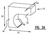
上方連結要素6は、前歯の方に向けられた凹面15を備えた実質的に鉛直な部分14を備え、下方連結要素5の接触部分7は、実質的に相補形の表面16を備えている。このようにして、上方連結要素が下方連結要素に係合可能となり、上顎に対する下顎の鉛直移動がさらに案内かつ制限されることとなる。 The upper connecting
図示された実施例に従うと、鉛直調整手段10および水平調整手段11は、いずれの場合にも、固定部分9に対して接触部分7を上方/下方および前方/後方に調整するためのダブルスクリューを備えた中心調整ねじ17および18からなる。各々の中心調整ねじ17および18の両側には、それらに対して平行であり入れ子式に作動する管22、23および24、25が配置されている(特に、図3(B)を参照)。中心の鉛直調整ねじ17は、一方の外端においては、接触部分7にある第1のねじ穴と協働し、他方の外端においては、中心部分8にある第2のねじ穴と協働する。この場合、調整ねじの回転により、第1のねじ穴と第2のねじ穴との間の距離が変化する。中心の水平調整ねじ18は、一方側では中心部分8にあるねじ穴と協働し、他方側では固定部分9にあるねじ穴と協働する。調整ねじ17および18は各々、好ましくは、実質的にその中心に環状フランジ21を備えており、当該環状フランジ21は径方向の開口部20を有しており、当該開口部20にロッドが嵌まり込んでいる。これは、ロッドを回転させることによって調整ねじを回転させることを目的としたものである。 According to the illustrated embodiment, the vertical adjustment means 10 and the horizontal adjustment means 11 are in each case provided with a double screw for adjusting the
図3(A)は上方連結要素6を詳細に示す。この要素6の寸法は、たとえば以下のとおりであり得る。 FIG. 3A shows the upper connecting
・5mm〜10mmの幅w1、好ましくは約8mm;
・10mm〜20mmの高さh1、好ましくは約15mm;
・10mm〜20mmの長さl1、好ましくは約15mm。A width w1 of 5 mm to 10 mm, preferably about 8 mm;
A height h1 of 10 mm to 20 mm, preferably about 15 mm;
A length l1 of 10 mm to 20 mm, preferably about 15 mm.
図3(B)は下方連結要素5を詳細に示す。この要素5の寸法は、たとえば以下のとおりであり得る。 FIG. 3 (B) shows the lower connecting
・幅w1よりも小さな幅w2、たとえば4mm〜9mm、好ましくは、w1よりも小さな約2mm、さらにより好ましくは約6mm;
・15mm〜25mmの高さh2、好ましくは約18mm;
・20mm〜40mmの長さl2、好ましくは約32mm。A width w2 smaller than the width w1, eg 4 mm to 9 mm, preferably about 2 mm smaller than w1, even more preferably about 6 mm;
A height h2 of 15 mm to 25 mm, preferably about 18 mm;
A length l2 between 20 mm and 40 mm, preferably about 32 mm.
有利な実施例に従うと、各々の上方連結要素6は、口内に配置された口腔装置の位置においては下方連結要素に対して制限された態様で(図4における矢印30を参照)横方向または横向きに移動可能である。図4に示される有利な実施例においては、この目的のために、上方連結要素6の幅w2は下方連結要素5の幅w1よりも小さくなっており、下方連結要素はさらに外側に配置される(ここでは、距離w1−w2にわたって配置される。但し、当業者であれば、この距離が、ある程度まではより短くてもまたはより長くてもよいことを認識するだろう)。このように、装置が口内に配置されると、下方連結要素5が上方部分から横方向に離れて位置することとなり、こうして、上方部分が下方部分に対して横方向に移動することが可能となるだろう。 According to an advantageous embodiment, each upper connecting
ここで、いくつかの変形例を、図2(A)〜図2(E)に示される概略的な側面図を参照しながら説明するが、明確にするために下方部分および上方部分は図示しない。 Several variations will now be described with reference to the schematic side views shown in FIGS. 2A-2E, but the lower and upper portions are not shown for clarity. .
図2(A)の変形例においては、水平調整手段は設けられておらず、下方連結要素105は、基部109および接触部分107という2つの部分から構成されている。接触部分107は接触面112を有しており、その高さは、鉛直調整手段110を用いて調整可能である。図2(B)は同等の変形例を示しており、基部209および鉛直に調整可能な接触部分207が上方連結要素206に設けられ、止め具213が接触部分207の底部に位置し、接触面212が下方連結要素205上に設けられている。 In the modification of FIG. 2A, no horizontal adjustment means is provided, and the lower connecting
図2(C)の変形例は、大部分が図1の実施例と一致しており、このため、図1の上述の記載を参照することができる。図2(D)が示す逆の変形例においては、関連する鉛直調整手段310および水平調整手段311を備えた部分307、308および309が上方連結要素306に収容されている。ここでは、下方連結要素305は、凸面315を備えた鉛直部分314を備え、接触部分307には相補形の表面316が形成されている。 The modification of FIG. 2 (C) is mostly consistent with the embodiment of FIG. 1, and therefore, the above description of FIG. 1 can be referred to. In the reverse modification shown in FIG. 2 (D),
図2(E)が示す変形例においては、前歯440の方に向けられた凸面415を備えた鉛直部分414が上方連結要素に設けられている。この凸面は、一方側では、接触部分407のための、閉口移動を防ぐ止め具413を形成し、他方側では、相補的な表面412/416を備えた部分407の鉛直移動を案内および制限するためのガイド面を形成している。最後に、図2(F)が示す変形例においては、水平調整手段511が、上方連結要素506において、上方部分に取付けられた固定部分508と、鉛直部分514および止め具513を備えた止め部との間に設けられている。鉛直調整手段510は、下方連結要素505において、接触部分507と固定部分509との間に設けられる。 In the modification shown in FIG. 2 (E), a
当業者であれば、図が限定的なものではなく、一変形例の測定値が、本発明の範囲から逸脱することなく別の変形例に追加可能であることを認識するだろう。図2Fの実施例における一方側の要素513および514ならびに他方側の要素507の設計は、たとえばこのように変更可能であり、また、たとえば、図1の実施例における一方側の要素13および14ならびに他方側の要素7の設計に類似していてもよい。 One of ordinary skill in the art will recognize that the figures are not limiting and that one variation of measurements can be added to another variation without departing from the scope of the present invention. The design of
本発明は、上に説明された具体的な実施例に限定されるものではなく、当業者であれば、添付の特許請求の範囲によってのみ定義される本発明の範囲から逸脱することなく多くの変更例が想定可能であることを理解するだろう。 The present invention is not limited to the specific embodiments described above, and those skilled in the art will recognize many variations without departing from the scope of the present invention, which is defined only by the appended claims. You will understand that changes are possible.
Claims (12)
Translated fromJapanese・下顎に取付け可能な下方部分と、上顎に取付け可能な上方部分とを含み、前記下方部分および上方部分は、少なくとも奥歯の付近に位置しており、前記装置はさらに、
・下方部分を奥歯付近で上方部分に連結するための左および右の連結手段を含み、左および右の連結手段の各々は、上方部分に接続された上方連結要素と、下方部分に接続された下方連結要素とを含み、左および右の連結手段は、上顎に対して下顎を前方に移動させるよう適合され、
上方連結要素および下方連結要素は、口内に配置された装置の位置において口腔前庭に位置するように、上方部分および下方部分にそれぞれ接続されており、
上方連結要素は、下方連結要素の接触面との協働用の止め具を備えており、これにより、下顎および上顎が互いの方に移動した場合に、接触面が止め具に当たったときにさらなる閉口が防止される、装置。A device for treating respiratory disorders,
A lower part attachable to the lower jaw and an upper part attachable to the upper jaw, wherein the lower part and the upper part are located at least near the back teeth, the device further comprising:
-Including left and right coupling means for coupling the lower part to the upper part near the back teeth, each of the left and right coupling means being connected to an upper coupling element connected to the upper part and to the lower part The left and right coupling means are adapted to move the lower jaw forward relative to the upper jaw,
The upper and lower coupling elements are connected to the upper and lower parts respectively so as to be located in the oral vestibule at the position of the device placed in the mouth,
The upper connecting element is provided with a stop for cooperating with the contact surface of the lower connecting element so that when the lower jaw and the upper jaw move towards each other, the contact surface hits the stop Device that prevents further closure.
Applications Claiming Priority (3)
| Application Number | Priority Date | Filing Date | Title |
|---|---|---|---|
| BE2008/0374ABE1018209A5 (en) | 2008-07-07 | 2008-07-07 | DEVICE FOR TREATING NIGHT-BREATHING RESPIRATORY PROBLEMS. |
| BE2008/0374 | 2008-07-07 | ||
| PCT/BE2009/000037WO2010003198A2 (en) | 2008-07-07 | 2009-07-06 | Device for treating night time breathing problems |
Publications (1)
| Publication Number | Publication Date |
|---|---|
| JP2011526821Atrue JP2011526821A (en) | 2011-10-20 |
Family
ID=40380009
Family Applications (1)
| Application Number | Title | Priority Date | Filing Date |
|---|---|---|---|
| JP2011516929APendingJP2011526821A (en) | 2008-07-07 | 2009-07-06 | Device for treating breathing disorders at night |
Country Status (10)
| Country | Link |
|---|---|
| US (1) | US8517029B2 (en) |
| EP (1) | EP2331036B1 (en) |
| JP (1) | JP2011526821A (en) |
| CN (1) | CN102112072B (en) |
| AU (1) | AU2009267736B2 (en) |
| BE (1) | BE1018209A5 (en) |
| BR (1) | BRPI0915476A2 (en) |
| CA (1) | CA2729913A1 (en) |
| IL (1) | IL210441A0 (en) |
| WO (1) | WO2010003198A2 (en) |
Families Citing this family (48)
| Publication number | Priority date | Publication date | Assignee | Title |
|---|---|---|---|---|
| US8316857B2 (en)* | 2006-04-06 | 2012-11-27 | Airway Technologies, Llc | Oral appliance for treating a breathing condition |
| US8316858B2 (en)* | 2006-04-06 | 2012-11-27 | Airway Technologies, Llc | System for coupling an oral appliance to a medical mask |
| US7748386B2 (en) | 2006-04-06 | 2010-07-06 | Thornton W Keith | Oral appliance for treating a breathing condition |
| US8607796B2 (en) | 2009-02-27 | 2013-12-17 | Airway Technologies, Llc | Apparatus and method for coupling an oral appliance to a gas delivery device |
| US8573224B2 (en) | 2009-10-16 | 2013-11-05 | Airway Technologies, Llc | Custom-molded oral appliance and method of forming |
| US8671946B2 (en) | 2011-04-05 | 2014-03-18 | Airway Technologies, Llc | Custom dental appliance and method of creating a custom dental appliance |
| US8783261B2 (en) | 2011-04-05 | 2014-07-22 | Airway Technologies, Llc | Apparatus for prevention of snoring and improved breathing |
| US8662084B2 (en) | 2011-04-05 | 2014-03-04 | Airway Technologies, Llc | Universal oral appliance with a universal coupler |
| WO2012138459A1 (en) | 2011-04-05 | 2012-10-11 | Airway Technologies, Llc | Oral appliance for treating particular disorders associated with sleep |
| US20130112210A1 (en)* | 2011-11-03 | 2013-05-09 | Ivan F. STEIN | Oral Sleep Apnea Device |
| USD718449S1 (en)* | 2011-11-23 | 2014-11-25 | Somnomed Limited | Set of oral appliances |
| USD718448S1 (en)* | 2011-11-23 | 2014-11-25 | Somnomed Limited | Set of oral appliances |
| SE538339C2 (en) | 2012-06-19 | 2016-05-24 | Dental Device Sweden Ab | Device for the treatment of sleep apnea or snoring |
| USD704843S1 (en)* | 2012-06-29 | 2014-05-13 | Gurdev Dave Singh | Sleep appliance |
| EP2908770B1 (en) | 2012-10-16 | 2019-04-24 | Cook Medical Technologies LLC | Apparatus for treating obstructive sleep apnea (osa) |
| AU2014306232B2 (en) | 2013-08-05 | 2018-12-06 | C2Dx, Inc. | Medical devices having a releasable tubular member and methods of using the same |
| US20150075540A1 (en)* | 2013-09-17 | 2015-03-19 | Brian Douglas Dye | Apparatus for the prevention of sleep apnea |
| CN104688404A (en)* | 2013-12-04 | 2015-06-10 | 肯尼斯·卢科 | An oral appliance for treating obstructive sleep apnea (OSA) and sleep bruxism |
| WO2015123528A1 (en)* | 2014-02-13 | 2015-08-20 | Silverfox Dental & Ortho, Llc | Oral motion preservation device |
| US9974563B2 (en) | 2014-05-28 | 2018-05-22 | Cook Medical Technologies Llc | Medical devices having a releasable member and methods of using the same |
| WO2016004415A1 (en)* | 2014-07-02 | 2016-01-07 | Selane Products, Inc. | Sleep apnea oral appliance for use during orthodontic treatment |
| WO2016022454A1 (en) | 2014-08-04 | 2016-02-11 | Darin Schaeffer | Medical devices having a releasable tubular member and methods of using the same |
| US10376408B2 (en) | 2014-08-25 | 2019-08-13 | Airway Technologies, Llc | Oral appliance |
| US11426304B2 (en) | 2014-08-25 | 2022-08-30 | Airway Technologies, Llc | Oral appliance |
| EP3232980B1 (en) | 2014-12-16 | 2020-08-05 | Selane Products, Inc. | Adjustable sleep apnea oral appliance |
| US10258319B2 (en) | 2015-05-18 | 2019-04-16 | Richard L. Arden | Airway assist device and method |
| US10010313B2 (en) | 2015-05-18 | 2018-07-03 | Richard L. Arden | Mandibular subluxation device and method |
| US10342526B2 (en) | 2015-07-01 | 2019-07-09 | Richard L. Arden | Airway assist device and method |
| GB201602386D0 (en)* | 2015-07-08 | 2016-03-23 | Aria Healthcare Ltd | Improvements to oral devices |
| US9655695B2 (en)* | 2015-08-06 | 2017-05-23 | Gregory K. Ross | Oral apparatuses and methods for mandibular jaw manipulation |
| US20170042725A1 (en)* | 2015-08-12 | 2017-02-16 | Silverfox Dental & Ortho, Llc | Oral motion preservation device |
| JP6903343B2 (en) | 2015-11-30 | 2021-07-14 | セラン プロダクツ, インコーポレイテッドSelane Products, Inc. | Adjustable sleep apnea oral device |
| US10265213B2 (en)* | 2016-03-25 | 2019-04-23 | Jae Il Lim | Temporomandibular joint correction apparatus with exchangeable adjustor |
| JP6726741B2 (en)* | 2016-06-28 | 2020-07-22 | 三井化学株式会社 | Mouthpiece |
| US20200121493A1 (en)* | 2016-12-27 | 2020-04-23 | Mitsui Chemicals, Inc. | Mouthpiece |
| USD827835S1 (en)* | 2017-02-22 | 2018-09-04 | Philip Bocala | Oral sleep apnea and snoring device |
| US10603207B2 (en) | 2017-07-17 | 2020-03-31 | ProSomnus Sleep Technologies, Inc. | Mandibular advancement device with guide channel |
| WO2019077586A1 (en) | 2017-10-20 | 2019-04-25 | Beck Medical, Ltd. | Nasal device for treatment |
| USD870894S1 (en) | 2018-07-19 | 2019-12-24 | Greg Ross | Jaw manipulation appliance |
| CN110547904A (en)* | 2019-10-05 | 2019-12-10 | 扬州市君瑞企业管理有限公司 | Simple snore preventing device for hospital physiotherapy and rehabilitation |
| AU2020381572A1 (en)* | 2019-11-15 | 2022-06-02 | Raghavendra Vitthalrao GHUGE | Dynamic mandibular and lingual repositioning devices, controller station, and methods of treating and/or diagnosing medical disorders |
| US11666477B2 (en) | 2019-11-15 | 2023-06-06 | Sleep Solutions Of Texas, Llc | Lingual repositioning devices, controller station, and methods of treating and/or diagnosing medical disorders |
| US11666478B2 (en) | 2019-11-15 | 2023-06-06 | Sleep Solutions Of Texas, Llc | Maxillary devices, controller station, and methods of treating and/or diagnosing medical disorders |
| USD932626S1 (en) | 2020-05-13 | 2021-10-05 | ProSomnus Sleep Technologies, Inc. | Mandibular advancement device with comfort bumps |
| EP4243745A4 (en)* | 2020-11-14 | 2024-10-09 | Sleep Solutions of Texas, LLC | UPPER AND LOWER JAW DEVICES, CONTROL STATION |
| IT202100015263A1 (en)* | 2021-06-11 | 2022-12-11 | Fabrizio Anelli | MANDIBULAR ADVANCEMENT DEVICE TO TREAT SLEEP APNEA AND SPACER KIT FOR A MANDIBULAR ADVANCEMENT DEVICE |
| US12318325B2 (en)* | 2021-07-02 | 2025-06-03 | Sleep Solutions Of Texas, Llc | Maxillary and mandibular devices that prevent disengagement therebetween, controller station, and methods of treating and/or diagnosing medical disorders |
| US12403033B2 (en)* | 2023-04-21 | 2025-09-02 | Achaemenid, Llc | Oral appliance for the treatment of sleep apnea |
Citations (8)
| Publication number | Priority date | Publication date | Assignee | Title |
|---|---|---|---|---|
| JP2002519137A (en)* | 1998-07-06 | 2002-07-02 | リチャード・ジョージ・パルミサノ | Mandible advancement device |
| EP1516604A1 (en)* | 2003-09-16 | 2005-03-23 | Dr. Hinz Labor, Fachlaboratorium für Kieferorthopädie GmbH & Co. KG | Intra-oral therapeutic device |
| US7007697B1 (en)* | 2003-06-16 | 2006-03-07 | Nicholas Della Grotta | Respiration assisting and snore reducing apparatus |
| JP2007501641A (en)* | 2003-08-08 | 2007-02-01 | ネリッセン,ヨゼフ・フランス | Device for treating nocturnal breathing disorders |
| WO2007113465A1 (en)* | 2006-04-04 | 2007-10-11 | Sleepworks Products Ltd | Device to reduce snoring and sleep apnoea |
| US20070283967A1 (en)* | 2006-06-12 | 2007-12-13 | Bailey Dennis R | Anti-Retrusion Oral Appliance |
| WO2008060122A1 (en)* | 2006-11-17 | 2008-05-22 | Seung-Kyu Lee | Device for snoring prevention |
| EP1972311A1 (en)* | 2007-03-20 | 2008-09-24 | Bredent GmbH & Co. KG | Biocompatible treatment device for providing therapy for snoring and sleep-related breathing disturbances |
Family Cites Families (3)
| Publication number | Priority date | Publication date | Assignee | Title |
|---|---|---|---|---|
| US5868138A (en)* | 1993-04-13 | 1999-02-09 | Silent Knight Ventures, Inc. | Dental appliance for treatment of snoring and obstructive sleep apnea |
| CN1091366C (en)* | 1999-04-21 | 2002-09-25 | 卢崇伟 | Snore treating device |
| CN201157439Y (en)* | 2008-01-25 | 2008-12-03 | 宋冬生 | Snore inhibitor |
- 2008
- 2008-07-07BEBE2008/0374Apatent/BE1018209A5/enactive
- 2009
- 2009-07-06CNCN2009801305220Apatent/CN102112072B/ennot_activeExpired - Fee Related
- 2009-07-06BRBRPI0915476Apatent/BRPI0915476A2/ennot_activeApplication Discontinuation
- 2009-07-06CACA2729913Apatent/CA2729913A1/ennot_activeAbandoned
- 2009-07-06JPJP2011516929Apatent/JP2011526821A/enactivePending
- 2009-07-06WOPCT/BE2009/000037patent/WO2010003198A2/enactiveApplication Filing
- 2009-07-06AUAU2009267736Apatent/AU2009267736B2/ennot_activeExpired - Fee Related
- 2009-07-06EPEP09775649.8Apatent/EP2331036B1/enactiveActive
- 2009-07-06USUS13/002,499patent/US8517029B2/enactiveActive
- 2011
- 2011-01-03ILIL210441Apatent/IL210441A0/enunknown
Patent Citations (9)
| Publication number | Priority date | Publication date | Assignee | Title |
|---|---|---|---|---|
| JP2002519137A (en)* | 1998-07-06 | 2002-07-02 | リチャード・ジョージ・パルミサノ | Mandible advancement device |
| US7007697B1 (en)* | 2003-06-16 | 2006-03-07 | Nicholas Della Grotta | Respiration assisting and snore reducing apparatus |
| JP2007501641A (en)* | 2003-08-08 | 2007-02-01 | ネリッセン,ヨゼフ・フランス | Device for treating nocturnal breathing disorders |
| EP1516604A1 (en)* | 2003-09-16 | 2005-03-23 | Dr. Hinz Labor, Fachlaboratorium für Kieferorthopädie GmbH & Co. KG | Intra-oral therapeutic device |
| WO2007113465A1 (en)* | 2006-04-04 | 2007-10-11 | Sleepworks Products Ltd | Device to reduce snoring and sleep apnoea |
| US20070283967A1 (en)* | 2006-06-12 | 2007-12-13 | Bailey Dennis R | Anti-Retrusion Oral Appliance |
| WO2008060122A1 (en)* | 2006-11-17 | 2008-05-22 | Seung-Kyu Lee | Device for snoring prevention |
| JP2010509980A (en)* | 2006-11-17 | 2010-04-02 | リー・セウン・キュ | Snoring prevention equipment |
| EP1972311A1 (en)* | 2007-03-20 | 2008-09-24 | Bredent GmbH & Co. KG | Biocompatible treatment device for providing therapy for snoring and sleep-related breathing disturbances |
Also Published As
| Publication number | Publication date |
|---|---|
| AU2009267736A1 (en) | 2010-01-14 |
| BRPI0915476A2 (en) | 2016-09-06 |
| CA2729913A1 (en) | 2010-01-14 |
| BE1018209A5 (en) | 2010-07-06 |
| CN102112072A (en) | 2011-06-29 |
| CN102112072B (en) | 2013-08-28 |
| WO2010003198A2 (en) | 2010-01-14 |
| IL210441A0 (en) | 2011-03-31 |
| WO2010003198A3 (en) | 2010-05-14 |
| EP2331036A2 (en) | 2011-06-15 |
| EP2331036B1 (en) | 2019-11-06 |
| AU2009267736B2 (en) | 2014-05-15 |
| US20110168187A1 (en) | 2011-07-14 |
| US8517029B2 (en) | 2013-08-27 |
Similar Documents
| Publication | Publication Date | Title |
|---|---|---|
| JP2011526821A (en) | Device for treating breathing disorders at night | |
| JP4709146B2 (en) | Device for treating nocturnal breathing disorders | |
| US11246744B2 (en) | Device for moving lower jaw forward | |
| US7637262B2 (en) | Anti-retrusion oral appliance | |
| US20080115791A1 (en) | Mandibular Advancement Mouthpiece, An Intraoccusal Removable Improved Device For Eliminating Or Reducing Snoring | |
| US7810502B1 (en) | Anti-snoring and obstructive sleep apnea device | |
| KR101782093B1 (en) | Prevention instrument for snore and bruxism | |
| US20170095951A1 (en) | Oral appliance for treatment of snoring and sleep apnea | |
| CN104582646B (en) | anti-snoring device | |
| KR20120077985A (en) | Apparatus for preventing from snoring with an snoring relative seriousness of subject | |
| US20150034093A1 (en) | Method and Apparatus for Incrementally Repositioning the Mandible of a Patient | |
| KR101481801B1 (en) | Orthopedic appliances for temporomandibular jiont and the wing spacer | |
| KR101572127B1 (en) | Oral appliance for treating sleep-related breathing disorders | |
| WO2011146419A1 (en) | Oral appliance with adjustment assembly | |
| TWM603345U (en) | Mandible displacement adjusting device | |
| TWI737347B (en) | Mandible displacement adjusting device | |
| KR102805930B1 (en) | Mandibular adjustment device | |
| TWI726787B (en) | Mandible adjustment device |
Legal Events
| Date | Code | Title | Description |
|---|---|---|---|
| A621 | Written request for application examination | Free format text:JAPANESE INTERMEDIATE CODE: A621 Effective date:20120614 | |
| A131 | Notification of reasons for refusal | Free format text:JAPANESE INTERMEDIATE CODE: A131 Effective date:20130709 | |
| A02 | Decision of refusal | Free format text:JAPANESE INTERMEDIATE CODE: A02 Effective date:20131203 |