JP2011524205A - System and method for delivering energy to tissue - Google Patents
System and method for delivering energy to tissueDownload PDFInfo
- Publication number
- JP2011524205A JP2011524205AJP2011513707AJP2011513707AJP2011524205AJP 2011524205 AJP2011524205 AJP 2011524205AJP 2011513707 AJP2011513707 AJP 2011513707AJP 2011513707 AJP2011513707 AJP 2011513707AJP 2011524205 AJP2011524205 AJP 2011524205A
- Authority
- JP
- Japan
- Prior art keywords
- tissue
- transducer assembly
- skin surface
- handpiece
- cooling
- Prior art date
- Legal status (The legal status is an assumption and is not a legal conclusion. Google has not performed a legal analysis and makes no representation as to the accuracy of the status listed.)
- Pending
Links
- 238000000034methodMethods0.000titleclaimsabstractdescription44
- 238000002604ultrasonographyMethods0.000claimsabstractdescription42
- 210000001519tissueAnatomy0.000claimsdescription194
- 210000003491skinAnatomy0.000claimsdescription119
- 238000001816coolingMethods0.000claimsdescription82
- 102000008186CollagenHuman genes0.000claimsdescription30
- 108010035532CollagenProteins0.000claimsdescription30
- 229920001436collagenPolymers0.000claimsdescription30
- 239000012530fluidSubstances0.000claimsdescription29
- 238000010438heat treatmentMethods0.000claimsdescription20
- 230000033001locomotionEffects0.000claimsdescription17
- 239000000499gelSubstances0.000claimsdescription16
- 210000003462veinAnatomy0.000claimsdescription9
- 239000000126substanceSubstances0.000claimsdescription8
- 210000000577adipose tissueAnatomy0.000claimsdescription7
- 239000012809cooling fluidSubstances0.000claimsdescription7
- 235000015110jelliesNutrition0.000claimsdescription5
- 230000037303wrinklesEffects0.000claimsdescription5
- 239000002537cosmeticSubstances0.000claimsdescription4
- 210000005003heart tissueAnatomy0.000claimsdescription4
- 239000008274jellySubstances0.000claimsdescription4
- 230000009707neogenesisEffects0.000claimsdescription4
- 210000004927skin cellAnatomy0.000claimsdescription4
- WYTGDNHDOZPMIW-RCBQFDQVSA-NalstonineNatural productsC1=CC2=C3C=CC=CC3=NC2=C2N1C[C@H]1[C@H](C)OC=C(C(=O)OC)[C@H]1C2WYTGDNHDOZPMIW-RCBQFDQVSA-N0.000claimsdescription3
- 230000003020moisturizing effectEffects0.000claimsdescription3
- 230000000916dilatatory effectEffects0.000claims1
- 229940079593drugDrugs0.000claims1
- 239000003814drugSubstances0.000claims1
- 238000007920subcutaneous administrationMethods0.000abstractdescription9
- 230000001225therapeutic effectEffects0.000abstractdescription3
- 239000010410layerSubstances0.000description56
- 238000002560therapeutic procedureMethods0.000description25
- 239000000463materialSubstances0.000description19
- 230000007246mechanismEffects0.000description17
- 238000013459approachMethods0.000description13
- 230000006870functionEffects0.000description11
- 210000004207dermisAnatomy0.000description9
- 239000007921spraySubstances0.000description8
- 210000002615epidermisAnatomy0.000description6
- 230000001965increasing effectEffects0.000description6
- 230000000694effectsEffects0.000description5
- 238000012546transferMethods0.000description5
- 238000004299exfoliationMethods0.000description4
- 239000000835fiberSubstances0.000description4
- 230000003993interactionEffects0.000description4
- 229910052451lead zirconate titanateInorganic materials0.000description4
- 239000004033plasticSubstances0.000description4
- 239000011149active materialSubstances0.000description3
- 230000032683agingEffects0.000description3
- 238000005452bendingMethods0.000description3
- 230000006378damageEffects0.000description3
- 238000010586diagramMethods0.000description3
- 229910052751metalInorganic materials0.000description3
- 239000002184metalSubstances0.000description3
- 238000007669thermal treatmentMethods0.000description3
- IJGRMHOSHXDMSA-UHFFFAOYSA-NAtomic nitrogenChemical compoundN#NIJGRMHOSHXDMSA-UHFFFAOYSA-N0.000description2
- 208000032544CicatrixDiseases0.000description2
- 244000261422Lysimachia clethroidesSpecies0.000description2
- 238000002679ablationMethods0.000description2
- 230000000712assemblyEffects0.000description2
- 238000000429assemblyMethods0.000description2
- 230000004888barrier functionEffects0.000description2
- 239000000919ceramicSubstances0.000description2
- 239000003795chemical substances by applicationSubstances0.000description2
- 210000002808connective tissueAnatomy0.000description2
- 239000000110cooling liquidSubstances0.000description2
- 230000007613environmental effectEffects0.000description2
- 210000003195fasciaAnatomy0.000description2
- 230000035876healingEffects0.000description2
- 238000003384imaging methodMethods0.000description2
- HFGPZNIAWCZYJU-UHFFFAOYSA-Nlead zirconate titanateChemical compound[O-2].[O-2].[O-2].[O-2].[O-2].[Ti+4].[Zr+4].[Pb+2]HFGPZNIAWCZYJU-UHFFFAOYSA-N0.000description2
- YWAKXRMUMFPDSH-UHFFFAOYSA-NpenteneChemical compoundCCCC=CYWAKXRMUMFPDSH-UHFFFAOYSA-N0.000description2
- 239000010453quartzSubstances0.000description2
- 230000005855radiationEffects0.000description2
- 230000003716rejuvenationEffects0.000description2
- 231100000241scarToxicity0.000description2
- 230000037387scarsEffects0.000description2
- VYPSYNLAJGMNEJ-UHFFFAOYSA-Nsilicon dioxideInorganic materialsO=[Si]=OVYPSYNLAJGMNEJ-UHFFFAOYSA-N0.000description2
- 239000000243solutionSubstances0.000description2
- 230000007704transitionEffects0.000description2
- 238000012285ultrasound imagingMethods0.000description2
- 208000002874Acne VulgarisDiseases0.000description1
- 229910001316Ag alloyInorganic materials0.000description1
- 241000283690Bos taurusSpecies0.000description1
- OKTJSMMVPCPJKN-UHFFFAOYSA-NCarbonChemical compound[C]OKTJSMMVPCPJKN-UHFFFAOYSA-N0.000description1
- 102000016942ElastinHuman genes0.000description1
- 108010014258ElastinProteins0.000description1
- 229920002683GlycosaminoglycanPolymers0.000description1
- 206010020751HypersensitivityDiseases0.000description1
- 239000002033PVDF binderSubstances0.000description1
- ISWSIDIOOBJBQZ-UHFFFAOYSA-NPhenolChemical compoundOC1=CC=CC=C1ISWSIDIOOBJBQZ-UHFFFAOYSA-N0.000description1
- FAPWRFPIFSIZLT-UHFFFAOYSA-MSodium chlorideChemical compound[Na+].[Cl-]FAPWRFPIFSIZLT-UHFFFAOYSA-M0.000description1
- 238000010521absorption reactionMethods0.000description1
- 206010000496acneDiseases0.000description1
- 239000000853adhesiveSubstances0.000description1
- 230000001070adhesive effectEffects0.000description1
- 210000001789adipocyteAnatomy0.000description1
- 230000002238attenuated effectEffects0.000description1
- DUPIXUINLCPYLU-UHFFFAOYSA-Nbarium leadChemical compound[Ba].[Pb]DUPIXUINLCPYLU-UHFFFAOYSA-N0.000description1
- 229910002113barium titanateInorganic materials0.000description1
- JRPBQTZRNDNNOP-UHFFFAOYSA-Nbarium titanateChemical compound[Ba+2].[Ba+2].[O-][Ti]([O-])([O-])[O-]JRPBQTZRNDNNOP-UHFFFAOYSA-N0.000description1
- 235000013405beerNutrition0.000description1
- 230000015572biosynthetic processEffects0.000description1
- OJIJEKBXJYRIBZ-UHFFFAOYSA-Ncadmium nickelChemical compound[Ni].[Cd]OJIJEKBXJYRIBZ-UHFFFAOYSA-N0.000description1
- 210000005242cardiac chamberAnatomy0.000description1
- 230000008859changeEffects0.000description1
- 239000011248coating agentSubstances0.000description1
- 238000000576coating methodMethods0.000description1
- 239000004020conductorSubstances0.000description1
- 230000008602contractionEffects0.000description1
- 230000008878couplingEffects0.000description1
- 238000010168coupling processMethods0.000description1
- 238000005859coupling reactionMethods0.000description1
- 230000003247decreasing effectEffects0.000description1
- 238000004925denaturationMethods0.000description1
- 230000036425denaturationEffects0.000description1
- NKZSPGSOXYXWQA-UHFFFAOYSA-Ndioxido(oxo)titanium;lead(2+)Chemical compound[Pb+2].[O-][Ti]([O-])=ONKZSPGSOXYXWQA-UHFFFAOYSA-N0.000description1
- 238000002845discolorationMethods0.000description1
- 235000012489doughnutsNutrition0.000description1
- 230000002500effect on skinEffects0.000description1
- 229920002549elastinPolymers0.000description1
- 229920001971elastomerPolymers0.000description1
- 210000002919epithelial cellAnatomy0.000description1
- 210000005081epithelial layerAnatomy0.000description1
- 210000000981epitheliumAnatomy0.000description1
- 238000001914filtrationMethods0.000description1
- 239000007789gasSubstances0.000description1
- 210000004907glandAnatomy0.000description1
- PCHJSUWPFVWCPO-UHFFFAOYSA-NgoldChemical compound[Au]PCHJSUWPFVWCPO-UHFFFAOYSA-N0.000description1
- 229910052737goldInorganic materials0.000description1
- 239000010931goldSubstances0.000description1
- 229910002804graphiteInorganic materials0.000description1
- 239000010439graphiteSubstances0.000description1
- 230000001939inductive effectEffects0.000description1
- 239000007924injectionSubstances0.000description1
- 238000002347injectionMethods0.000description1
- 238000007443liposuctionMethods0.000description1
- 239000007788liquidSubstances0.000description1
- GQYHUHYESMUTHG-UHFFFAOYSA-Nlithium niobateChemical compound[Li+].[O-][Nb](=O)=OGQYHUHYESMUTHG-UHFFFAOYSA-N0.000description1
- 230000007774longtermEffects0.000description1
- 238000013507mappingMethods0.000description1
- 229910001092metal group alloyInorganic materials0.000description1
- 150000002739metalsChemical class0.000description1
- 239000000203mixtureSubstances0.000description1
- 238000012986modificationMethods0.000description1
- 230000004048modificationEffects0.000description1
- 238000012544monitoring processMethods0.000description1
- 210000003205muscleAnatomy0.000description1
- 210000000944nerve tissueAnatomy0.000description1
- 229910052757nitrogenInorganic materials0.000description1
- 230000002093peripheral effectEffects0.000description1
- 230000035699permeabilityEffects0.000description1
- 229920000052poly(p-xylylene)Polymers0.000description1
- 239000011148porous materialSubstances0.000description1
- 238000011084recoveryMethods0.000description1
- 239000011347resinSubstances0.000description1
- 229920005989resinPolymers0.000description1
- 238000007665saggingMethods0.000description1
- 210000001732sebaceous glandAnatomy0.000description1
- 230000035939shockEffects0.000description1
- 239000004332silverSubstances0.000description1
- 230000037075skin appearanceEffects0.000description1
- 230000037394skin elasticityEffects0.000description1
- 239000011780sodium chlorideSubstances0.000description1
- 239000010935stainless steelSubstances0.000description1
- 229910001220stainless steelInorganic materials0.000description1
- 210000004003subcutaneous fatAnatomy0.000description1
- 230000036561sun exposureEffects0.000description1
- 239000002344surface layerSubstances0.000description1
- 239000000725suspensionSubstances0.000description1
- 210000004243sweatAnatomy0.000description1
- 229920002994synthetic fiberPolymers0.000description1
- 230000008685targetingEffects0.000description1
- 238000009210therapy by ultrasoundMethods0.000description1
- 230000003685thermal hair damageEffects0.000description1
- YNJBWRMUSHSURL-UHFFFAOYSA-Ntrichloroacetic acidChemical compoundOC(=O)C(Cl)(Cl)ClYNJBWRMUSHSURL-UHFFFAOYSA-N0.000description1
- 238000007740vapor depositionMethods0.000description1
- 230000037373wrinkle formationEffects0.000description1
- 230000037331wrinkle reductionEffects0.000description1
Images


Classifications
- A—HUMAN NECESSITIES
- A61—MEDICAL OR VETERINARY SCIENCE; HYGIENE
- A61N—ELECTROTHERAPY; MAGNETOTHERAPY; RADIATION THERAPY; ULTRASOUND THERAPY
- A61N7/00—Ultrasound therapy
- A—HUMAN NECESSITIES
- A61—MEDICAL OR VETERINARY SCIENCE; HYGIENE
- A61M—DEVICES FOR INTRODUCING MEDIA INTO, OR ONTO, THE BODY; DEVICES FOR TRANSDUCING BODY MEDIA OR FOR TAKING MEDIA FROM THE BODY; DEVICES FOR PRODUCING OR ENDING SLEEP OR STUPOR
- A61M37/00—Other apparatus for introducing media into the body; Percutany, i.e. introducing medicines into the body by diffusion through the skin
- A61M37/0092—Other apparatus for introducing media into the body; Percutany, i.e. introducing medicines into the body by diffusion through the skin using ultrasonic, sonic or infrasonic vibrations, e.g. phonophoresis
- A—HUMAN NECESSITIES
- A61—MEDICAL OR VETERINARY SCIENCE; HYGIENE
- A61B—DIAGNOSIS; SURGERY; IDENTIFICATION
- A61B17/00—Surgical instruments, devices or methods
- A61B2017/00017—Electrical control of surgical instruments
- A61B2017/00022—Sensing or detecting at the treatment site
- A61B2017/00075—Motion
- A—HUMAN NECESSITIES
- A61—MEDICAL OR VETERINARY SCIENCE; HYGIENE
- A61B—DIAGNOSIS; SURGERY; IDENTIFICATION
- A61B18/00—Surgical instruments, devices or methods for transferring non-mechanical forms of energy to or from the body
- A61B2018/00005—Cooling or heating of the probe or tissue immediately surrounding the probe
- A61B2018/00011—Cooling or heating of the probe or tissue immediately surrounding the probe with fluids
- A61B2018/00029—Cooling or heating of the probe or tissue immediately surrounding the probe with fluids open
- A—HUMAN NECESSITIES
- A61—MEDICAL OR VETERINARY SCIENCE; HYGIENE
- A61B—DIAGNOSIS; SURGERY; IDENTIFICATION
- A61B90/00—Instruments, implements or accessories specially adapted for surgery or diagnosis and not covered by any of the groups A61B1/00 - A61B50/00, e.g. for luxation treatment or for protecting wound edges
- A61B90/06—Measuring instruments not otherwise provided for
- A61B2090/061—Measuring instruments not otherwise provided for for measuring dimensions, e.g. length
- A—HUMAN NECESSITIES
- A61—MEDICAL OR VETERINARY SCIENCE; HYGIENE
- A61N—ELECTROTHERAPY; MAGNETOTHERAPY; RADIATION THERAPY; ULTRASOUND THERAPY
- A61N7/00—Ultrasound therapy
- A61N2007/0004—Applications of ultrasound therapy
- A61N2007/0008—Destruction of fat cells
- A—HUMAN NECESSITIES
- A61—MEDICAL OR VETERINARY SCIENCE; HYGIENE
- A61N—ELECTROTHERAPY; MAGNETOTHERAPY; RADIATION THERAPY; ULTRASOUND THERAPY
- A61N7/00—Ultrasound therapy
- A61N2007/0078—Ultrasound therapy with multiple treatment transducers
Landscapes
- Health & Medical Sciences (AREA)
- Engineering & Computer Science (AREA)
- Public Health (AREA)
- Biomedical Technology (AREA)
- Veterinary Medicine (AREA)
- Life Sciences & Earth Sciences (AREA)
- Animal Behavior & Ethology (AREA)
- General Health & Medical Sciences (AREA)
- Radiology & Medical Imaging (AREA)
- Nuclear Medicine, Radiotherapy & Molecular Imaging (AREA)
- Dermatology (AREA)
- Medical Informatics (AREA)
- Anesthesiology (AREA)
- Heart & Thoracic Surgery (AREA)
- Hematology (AREA)
- Thermotherapy And Cooling Therapy Devices (AREA)
- Surgical Instruments (AREA)
Abstract
Translated fromJapaneseDescription
Translated fromJapanese (発明の背景)
本発明は、概して医療デバイスおよび方法に関し、より具体的には、非侵襲性皮膚治療および深組織の硬化のための方法およびシステムに関する。(Background of the Invention)
The present invention relates generally to medical devices and methods, and more particularly to methods and systems for non-invasive skin treatment and deep tissue hardening.
皮膚は、太陽、寒さ、風などの環境の衝撃に耐える第一の障壁である。加齢と共に、環境要因は、皮膚がその若々しい外観を失い、しわを発現させる原因となる。人間の皮膚は、約100μmの厚さの表皮と、それに続いて表面から最大4mmまで届き得る真皮と、最後に皮下層とから作られる。これらの3つの層は、皮膚の全体的な外見(若々しいまたは老いた)を支配する。真皮は、エラスチンと、コラーゲンと、グリコサミノグリカン(glycosoaminoglycan)と、プロテオグリカンとから構成される。皮下層はまた、皮下層を通って進み、真皮コラーゲンと皮下層との間の結合を表す繊維状の垂直バンドを有する。コラーゲン繊維は、皮膚に強度と弾力性とを提供する。加齢および太陽への露出と共に、コラーゲンは弾力性(引張り強さ)を失い、その結果、皮膚は、若々しく張りのある外見を失う。驚くことではないが、皮膚の外見を若返らせるための多数の技術が説明されてきた。 The skin is the primary barrier to withstand environmental impacts such as the sun, cold, and wind. With aging, environmental factors cause the skin to lose its youthful appearance and develop wrinkles. Human skin is made up of an epidermis about 100 μm thick, followed by a dermis that can reach up to 4 mm from the surface, and finally a subcutaneous layer. These three layers govern the overall appearance (youthful or aged) of the skin. The dermis is composed of elastin, collagen, glycosaminoglycan, and proteoglycan. The subcutaneous layer also has a fibrous vertical band that travels through the subcutaneous layer and represents the bond between the dermal collagen and the subcutaneous layer. Collagen fibers provide the skin with strength and elasticity. With aging and sun exposure, collagen loses its elasticity (tensile strength) so that the skin loses its youthful and tense appearance. Not surprisingly, a number of techniques for rejuvenating the skin appearance have been described.
皮膚細胞新生の1つのアプローチは、コラーゲンを皮膚の中に物理的に注入することである。これは豊かなまたは肉付きのよい外見を与え、不快な線は滑らかにされる。ウシコラーゲンがこの目的のために用いられてきた。残念ながら、これは、この問題に対する長期にわたる解決策でもなければ完全な解決策でもなく、コラーゲン注入に対するアレルギー反応の報告がしばしばなされている。 One approach to skin cell neogenesis is to physically inject collagen into the skin. This gives a rich or plump appearance and unpleasant lines are smoothed. Bovine collagen has been used for this purpose. Unfortunately, this is neither a long-term solution nor a complete solution to this problem, and allergic reactions to collagen injections are often reported.
コラーゲンが、熱処理の影響を受けやすく、コラーゲンの遷移温度を越えて加熱されると変性することは現在十分に立証されている。この変性は、コラーゲン繊維の収縮を伴い、この収縮は、たるんだ皮膚またはしわの寄った皮膚に張りのある若々しい外見を提供し得る。熱および化学をベースにしたアプローチは、共に、コラーゲンを収縮するように説明され、用いられてきた。 It is now well established that collagen is susceptible to heat treatment and denatures when heated above the transition temperature of collagen. This denaturation is accompanied by contraction of the collagen fibers, which can provide a youthful appearance with tension on sagging or wrinkled skin. Both thermal and chemical based approaches have been described and used to shrink collagen.
皮膚の外側層のほとんどまたは全部を剥脱するかまたは除去することは、皮膚を若返らせる他の公知の方法である。剥脱は、化学的に、機械的に、または光熱的に達成され得る。化学的剥脱は、トリクロロ酢酸およびフェノールなどの化学薬品を用いて遂行される。剥脱の深さを制御することが不能であること、起こり得る変色、および傷跡のリスクは、化学的剥脱に関連する問題のうちのいくつかである。 Exfoliating or removing most or all of the outer skin layer is another known method of rejuvenating the skin. Exfoliation can be accomplished chemically, mechanically, or photothermally. Chemical exfoliation is accomplished using chemicals such as trichloroacetic acid and phenol. The inability to control the depth of exfoliation, possible discoloration, and the risk of scars are some of the problems associated with chemical exfoliation.
上記の方法は、侵襲性であるという問題があり、相当な量の痛みを伴う。これらの美容整形処置はすべて、概して選択的処置であり、痛みおよび時折の副作用は、そうでなければこれらの処置を受けたいと考える多くの人々にとってかなりの妨げであった。 The above methods have the problem of being invasive and involve a considerable amount of pain. All of these cosmetic procedures are generally selective, and pain and occasional side effects have been a significant hindrance for many who would otherwise want to receive these procedures.
侵襲性処置に関連する問題のいくつかを克服するために、レーザおよび無線周波数エネルギーベースのしわ減少治療が提案されてきた。例えば、特許文献1は、コラーゲンを加熱し、コラーゲンを収縮させるパルス光を用い、それによって皮膚の弾力性を回復させることを説明する。コラーゲンは、真皮および皮下層内に位置を定められて、表皮にはないので、コラーゲンを標的にするレーザは、表皮および真皮を貫通しなければならない。ビールの吸収の法則(Bier’s Law of absorption)により、レーザビームは、典型的には皮膚の表面において最も強烈である。このことは、結果として皮膚の上部層の容認できない加熱をもたらす。下にある層を所望の温度に維持しながら、皮膚の上部層を冷却する様々なアプローチが説明されてきた。1つのアプローチは、下にある層(および従ってコラーゲン)が加熱されながら、表面が冷えたままであるように表面に凍結剤を吹きつけることである。そのようなアプローチは、特許文献2に説明されている。特許文献1に説明されている別のアプローチは、皮膚の表面に接触する、氷、ゲルまたは水晶などの冷却された透過性物質を用いることである。冷却液の透過性は、レーザビームが異なる皮膚層を貫通することを可能にする。 To overcome some of the problems associated with invasive procedures, laser and radio frequency energy based wrinkle reduction therapies have been proposed. For example,
皮膚(表皮および真皮)の上部層の望まない加熱に関連する問題のいくつかを克服するために、特許文献3は、RFエネルギーと、皮膚の表面に置かれているRF電極を備えている装置とを用いることを説明する。メラノサイドおよび他の上皮細胞に、見た目は実質的に影響しない逆温度勾配が作られる。しかしながら、そのような非侵襲性方法でさえ、対象とする特定の部位すなわち真皮にエネルギーが効果的に集中させられないというかなりの制限を有する。 In order to overcome some of the problems associated with unwanted heating of the upper layers of the skin (epidermis and dermis), US Pat. Will be described. An inverse temperature gradient is created in melanoside and other epithelial cells that does not substantially affect the appearance. However, even such non-invasive methods have considerable limitations in that energy cannot be effectively concentrated at a particular site of interest, ie the dermis.
より上皮の層を加熱することなく真皮を加熱する他のアプローチが説明されてきた。これらのアプローチは、皮膚の表面を貫通して組織の中に入り、加熱する電気的伝導性針を用いることを伴う。特許文献4および特許文献5は、そのようなシステムを説明する。残念ながら、そのようなアプローチは、結果として、皮下層の広範囲に及ぶ加熱をもたらし、皮下層の脂肪を融解する可能性がある。このことは、組織の望まない傷跡にする。 Other approaches to heating the dermis without heating more epithelial layers have been described. These approaches involve using an electrically conductive needle that penetrates the surface of the skin, enters the tissue, and heats it.
特許文献6において説明されるように、組織を全体にかつ均一に加熱することを制限するように説明されてきた1つのアプローチは、組織の分割治療である。この特許文献の出願は、所望の形状の治療帯を皮膚に作るためにレーザエネルギーを用いることを説明し、治療されないところにおいて、健康な組織が治療された組織の部位間にある。このことは、治療されない組織が治癒および回復のプロセスに加わることを可能にする。 One approach that has been described to limit the heating of tissue throughout and evenly, as described in US Pat. This patent application describes the use of laser energy to create a desired shape of the treatment zone on the skin, where unhealthy tissue is between the sites of the treated tissue. This allows untreated tissue to participate in the healing and recovery process.
特許文献7において説明されるように、別のアプローチは、治療のために組織の部位に熱で損傷を与えることであった。しかしながら、このアプローチは、オペレータが治療すべき部位を決定するので、組織の画像化およびモニタリングをも提供する超音波に頼り、このアプローチを複雑にし、消費者製品には十分には適さなくする。 Another approach, as described in US Pat. No. 5,697,772, was to thermally damage a tissue site for treatment. However, this approach relies on ultrasound, which also provides tissue imaging and monitoring, as the operator determines the site to be treated, complicating the approach and making it not well suited for consumer products.
従って、市販のデバイスの潜在的な欠点のために、非侵襲性方法で深組織の硬化を生成する改善された方法およびデバイスを提供することが望ましい。そのようなデバイスが、針または他の侵襲性方法を用いることなく、そして超音波画像化に頼ることなく、皮膚の所望の深さに位置を定められる選択された標的部位に熱を加えることもまた望ましい。 Thus, it is desirable to provide improved methods and devices that produce deep tissue hardening in a non-invasive manner because of the potential shortcomings of commercially available devices. Such devices may also apply heat to selected target sites that are located at the desired depth of the skin without using needles or other invasive methods and without resorting to ultrasound imaging. It is also desirable.
(発明の概要)
本発明は、概して医療デバイスおよび方法に関し、より詳細には、超音波を用いて組織を治療するデバイスおよび方法に関する。(Summary of Invention)
The present invention relates generally to medical devices and methods, and more particularly to devices and methods for treating tissue using ultrasound.
本発明の第1の局面において、皮膚表面下の組織を非侵襲的に治療する超音波ベースのデバイスは、オペレータの手に適合するような人間工学的形状のハンドピースと、ハンドピースの遠位端の近くのトランスデューサアセンブリとを備えている。トランスデューサアセンブリは、超音波エネルギーを組織に送達するように適合している。冷却アセンブリはハンドピースに連結され、組織表面を選択可能に冷却する。電子コントローラは、超音波エネルギー源に動作可能に接続される。コントローラおよびトランスデューサアセンブリは、ハンドピースが皮膚表面に隣接して位置を決められると、皮膚表面下の組織を治療するように構成され、それによって、治療帯を囲む組織を熱で損傷することなく、皮膚表面下の治療帯を加熱する。 In a first aspect of the present invention, an ultrasound-based device for non-invasively treating tissue under the skin surface includes an ergonomic handpiece adapted to fit an operator's hand, and a distal end of the handpiece. And a transducer assembly near the end. The transducer assembly is adapted to deliver ultrasonic energy to the tissue. A cooling assembly is coupled to the handpiece to selectably cool the tissue surface. The electronic controller is operatively connected to the ultrasonic energy source. The controller and transducer assembly is configured to treat tissue below the skin surface when the handpiece is positioned adjacent to the skin surface, thereby preventing heat damage to the tissue surrounding the treatment zone, Heat the treatment zone below the skin surface.
トランスデューサアセンブリおよび冷却アセンブリは、単一のアセンブリに一体化され得る。トランスデューサアセンブリは、他のアセンブリと交換可能であり得、使い捨て可能であり得る。デバイスは、使い捨て可能ユニットに付着するように構成され得、使い捨て可能ユニットは、薬用化粧品、計量分配薬、保湿因子、皮膚細胞新生因子、およびそれらの組み合わせなどの
スキンケア物質を計量分配し得る。The transducer assembly and cooling assembly can be integrated into a single assembly. The transducer assembly can be interchangeable with other assemblies and can be disposable. The device can be configured to attach to a disposable unit, which can dispense skin care substances such as medicated cosmetics, dispensing agents, moisturizing factors, skin cell neogenesis factors, and combinations thereof.
冷却アセンブリは、周囲温度より低い約5℃〜20℃まで皮膚表面を冷却し得る。冷却は、流体、ゲル、ゼリー、または凍結剤を用いて達成され得る。冷却アセンブリは、周囲温度より低い約5℃〜20℃の皮膚表面温度を維持するように適合し得る。冷却アセンブリは、ハンドピース内に収納され得る。 The cooling assembly may cool the skin surface to about 5-20 ° C. below ambient temperature. Cooling can be achieved using fluids, gels, jellies, or cryogens. The cooling assembly may be adapted to maintain a skin surface temperature of about 5 ° C. to 20 ° C. below ambient temperature. The cooling assembly may be housed within the handpiece.
トランスデューサアセンブリは、約1MHz〜100MHzの範囲の超音波周波数を放出し得るか、または周波数範囲は、約4MHz〜50MHzであり得る。冷却アセンブリおよびトランスデューサアセンブリは、治療帯が皮膚表面下約1mm〜約9mmの範囲内にするように構成され得る。トランスデューサアセンブリは、組織の表面に対して65度〜115度の角度でエネルギーを送達するように適合し得る。 The transducer assembly can emit ultrasonic frequencies in the range of about 1 MHz to 100 MHz, or the frequency range can be about 4 MHz to 50 MHz. The cooling assembly and transducer assembly may be configured such that the treatment zone is in the range of about 1 mm to about 9 mm below the skin surface. The transducer assembly may be adapted to deliver energy at an angle of 65 degrees to 115 degrees relative to the tissue surface.
ハンドピースは、ハンドピースの遠位端の近くに複数のアパーチャを含み、アパーチャは冷却流体がアパーチャを通過することを可能にするように適合し得る。アパーチャは、キャステレイテッドパターンで形成され得る。トランスデューサアセンブリは、ハンドピースの遠位端から引っ込み得る。従って、ハンドピースの遠位端は、皮膚表面に接触し得るが、トランスデューサアセンブリ自体は、皮膚表面に接触しない場合がある。いくつかの実施形態において、トランスデューサアセンブリは、ディスク形のトランスデューサを含み得、他の実施形態において、トランスデューサアセンブリは、凹面形または凸面形の前面を有し得る。なおも他の実施形態において、トランスデューサアセンブリは、環状または長方形の形状であり得る。トランスデューサは、好ましくは皮膚表面に接触しないで、皮膚表面から10mm〜15mm離れ得る。トランスデューサアセンブリは、整列して配置される複数のトランスデューサを含み得る。トランスデューサアセンブリはまた、トランスデューサアセンブリに連結された音響整合層を含み得、音響整合層は、トランスデューサアセンブリからハンドピースの中に戻るエネルギーの反射を減少させるように適合している。トランスデューサアセンブリはまた、トランスデューサアセンブリに連結されたバッキング要素を有し得、バッキング要素はトランスデューサアセンブリのためのヒートシンクとして働くか、またはバッキング要素はハンドピースの遠位のトランスデューサアセンブリからエネルギーを反射する。デバイスはまた、ハンドピースに連結され、トランスデューサアセンブリと皮膚表面との間の距離を検出するように適合しているセンサを含み得る。ハンドピースは皮膚表面に対して可動であり得、デバイスは、皮膚表面に沿ったハンドピースの動作を検出するように適合している動作検出器を含み得、この場合、動作検出器は、動作がない場合トランスデューサへの出力が減少させられるかまたは切られるようにコントローラに動作可能に連結される。 The handpiece includes a plurality of apertures near the distal end of the handpiece, and the apertures can be adapted to allow cooling fluid to pass through the apertures. The aperture may be formed with a casted pattern. The transducer assembly can be retracted from the distal end of the handpiece. Thus, the distal end of the handpiece may contact the skin surface, but the transducer assembly itself may not contact the skin surface. In some embodiments, the transducer assembly can include a disk-shaped transducer, and in other embodiments, the transducer assembly can have a concave or convex front surface. In still other embodiments, the transducer assembly may be annular or rectangular in shape. The transducer can be 10 mm to 15 mm away from the skin surface, preferably without contacting the skin surface. The transducer assembly may include a plurality of transducers arranged in alignment. The transducer assembly may also include an acoustic matching layer coupled to the transducer assembly, the acoustic matching layer being adapted to reduce reflection of energy back from the transducer assembly into the handpiece. The transducer assembly may also have a backing element coupled to the transducer assembly, the backing element serving as a heat sink for the transducer assembly, or the backing element reflects energy from the transducer assembly distal to the handpiece. The device may also include a sensor coupled to the handpiece and adapted to detect the distance between the transducer assembly and the skin surface. The handpiece can be movable with respect to the skin surface, and the device can include a motion detector adapted to detect movement of the handpiece along the skin surface, in which case the motion detector If not, the output to the transducer is operably coupled to the controller so that it is reduced or turned off.
本発明の別の局面において、皮膚表面下の組織を非侵襲的に治療する超音波ベースのデバイスは、オペレータの手に適合するような人間工学的形状のハンドピースと、ハンドピースの遠位端の近くのトランスデューサアセンブリとを備えている。トランスデューサアセンブリは、超音波エネルギーを組織に送達するように適合している。冷却アセンブリはハンドピースに連結され、組織表面を選択可能に冷却する。コントローラは、超音波エネルギー源に接続される。コントローラおよびトランスデューサアセンブリは、ハンドピースが皮膚表面に隣接して位置を決められると、トランスデューサアセンブリと皮膚表面とが直接接触することなく、皮膚表面下の組織を治療するように構成される。これは、治療帯を囲む組織を熱で損傷することなく、皮膚表面下の加熱治療帯を生成する。 In another aspect of the invention, an ultrasound-based device for non-invasively treating tissue under the skin surface includes an ergonomic handpiece adapted to fit an operator's hand and the distal end of the handpiece. Near the transducer assembly. The transducer assembly is adapted to deliver ultrasonic energy to the tissue. A cooling assembly is coupled to the handpiece to selectably cool the tissue surface. The controller is connected to an ultrasonic energy source. The controller and transducer assembly is configured to treat tissue under the skin surface without direct contact between the transducer assembly and the skin surface when the handpiece is positioned adjacent to the skin surface. This creates a heat treatment zone below the skin surface without heat damaging the tissue surrounding the treatment zone.
本発明のなおも別の局面において、皮膚表面下の組織を非侵襲的に治療する方法は、皮膚表面に隣接する超音波ベースの治療デバイスの位置を決めることを含み、この場合、治療デバイスは冷却アセンブリとトランスデューサアセンブリとを含む。治療デバイスが皮膚表面に隣接して配置されると、皮膚表面を冷却される。トランスデューサアセンブリと皮膚表面とが直接に接触することなく治療デバイスが皮膚表面に隣接して保持されると、超音波エネルギーが皮膚の下の治療帯に送達される。これは、結果として、治療帯を囲む組織を熱で損傷することなく治療帯を加熱する。 In yet another aspect of the invention, a method of non-invasively treating tissue under the skin surface includes locating an ultrasound-based treatment device adjacent to the skin surface, wherein the treatment device comprises: A cooling assembly and a transducer assembly. When the treatment device is placed adjacent to the skin surface, the skin surface is cooled. When the treatment device is held adjacent to the skin surface without direct contact between the transducer assembly and the skin surface, ultrasonic energy is delivered to the treatment zone under the skin. This results in heating the treatment zone without damaging the tissue surrounding the treatment zone with heat.
超音波エネルギーを送達するステップは、組織内のコラーゲンを加熱し得、それによって、コラーゲンを締め付けるかまたは収縮させ、皮膚の表面上のしわの外見を最小限にする。超音波エネルギーはまた、脂肪組織を減少させ得るか、拡張蛇行静脈を閉じ得るか、または心臓組織を治療し得る。 The step of delivering ultrasonic energy can heat the collagen in the tissue, thereby tightening or shrinking the collagen and minimizing the appearance of wrinkles on the surface of the skin. Ultrasonic energy can also reduce adipose tissue, close dilated serpentine veins, or treat heart tissue.
冷却することは、皮膚表面を周囲温度より低い約5℃〜20℃に冷却することを含み得る。方法は、周囲温度より低い約5℃〜20℃の皮膚表面温度を維持することをさらに含み得る。冷却するステップは、トランスデューサアセンブリを通って流体を通過させること、流体を皮膚表面に送達することまたは冷却ゲル、ゼリー、または凍結剤を皮膚表面に送達することを含み得る。 Cooling may include cooling the skin surface to about 5 ° C. to 20 ° C. below ambient temperature. The method can further include maintaining a skin surface temperature of about 5 ° C. to 20 ° C. below ambient temperature. The cooling step may include passing fluid through the transducer assembly, delivering fluid to the skin surface, or delivering a cooling gel, jelly, or cryogen to the skin surface.
エネルギーを送達するステップは、約4MHz〜50MHzの範囲の超音波周波数を放出することを含み得、治療帯は、皮膚表面下約3mm〜約9mmの範囲内であり得る。 The step of delivering energy may include emitting an ultrasonic frequency in the range of about 4 MHz to 50 MHz, and the treatment zone may be in the range of about 3 mm to about 9 mm below the skin surface.
方法は、エネルギー送達角度を制御するように、トランスデューサアセンブリと皮膚表面との間の角度を調整することをさらに含み得る。送達角度は、組織の表面に対して65度〜115度であり得る。方法はまた、治療デバイスと皮膚表面との間の距離を感知することをさらに含み得る。治療帯の大きさおよび深さは、組織表面温度、超音波周波数、超音波エネルギー密度、皮膚表面に沿った治療デバイスの速度、およびこれらの組み合わせのうちの1つを調整することによって、制御され得る。方法は、皮膚表面に沿って治療デバイスを動かすことをさらに含み得る。トランスデューサアセンブリと皮膚表面との間に10〜15mmの間隙が維持され得る。皮膚表面に沿った治療デバイスの動作もまた検出され得る。動作がない場合、トランスデューサアセンブリへの出力は、減少させ得るかまたは除去され得る。 The method can further include adjusting the angle between the transducer assembly and the skin surface to control the energy delivery angle. The delivery angle can be between 65 degrees and 115 degrees relative to the surface of the tissue. The method may also further include sensing a distance between the treatment device and the skin surface. The size and depth of the treatment zone is controlled by adjusting one of tissue surface temperature, ultrasound frequency, ultrasound energy density, the speed of the treatment device along the skin surface, and combinations thereof. obtain. The method may further include moving the treatment device along the skin surface. A gap of 10-15 mm can be maintained between the transducer assembly and the skin surface. Movement of the treatment device along the skin surface can also be detected. In the absence of motion, the output to the transducer assembly can be reduced or eliminated.
これらおよび他の実施形態は、添付の図面に関係する以下の説明においてさらに詳細に説明される。 These and other embodiments are described in further detail in the following description related to the accompanying drawings.
(発明の詳細な説明)
本発明の好ましい実施形態の以下の説明は、それらの実施形態に本発明を限定することを意図するものではなく、むしろ当業者が本発明を作りそして用いることを可能にすることを意図する。(Detailed description of the invention)
The following description of preferred embodiments of the invention is not intended to limit the invention to those embodiments, but rather is intended to enable one of ordinary skill in the art to make and use the invention.
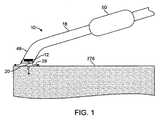
図1に示されるように、好ましい実施形態のエネルギー送達システム10は、エネルギーを組織276に向ける遠位チップアセンブリ48を含む。遠位チップアセンブリ48は、エネルギーの供給源を提供するエネルギー源12と、エネルギー源12および/または組織276を冷却する冷却機構とを含む。エネルギー送達システム10は、好ましくはエネルギーを組織に送達するように設計され、より具体的には、最外側組織層を実質的に損傷することなく、皮膚の表皮の下に位置を定められるコラーゲン組織または脂肪組織などの外側層の下のある深さにある組織にエネルギーを送達するように設計される。しかしながら、エネルギー送達システム10は、代わりに、任意の適切な組織に対して任意の適切な環境においてそして任意の適切な理由で用いられ得る。 As shown in FIG. 1, the preferred embodiment
遠位チップアセンブリ。図1に示されるように、好ましい実施形態の遠位チップアセンブリ48は、エネルギーを組織276に向けるように機能を果たし、好ましくはエネルギーの供給源を提供するように機能を果たし、エネルギービーム20を放出するエネルギー源12を収納する。遠位チップアセンブリ48は、エネルギー源12から放出されたエネルギービーム20を組織276に向け、その結果、エネルギービーム20は、適切な角度で標的組織276に接触する。放出されたエネルギービーム20は、好ましくは組織に対して20度〜160度の角度で標的組織に接触し、より好ましくは組織に対して45度〜135度の角度で標的組織に接触し、そして最も好ましくは組織に対して65度〜115度の角度で標的組織に接触する。遠位チップアセンブリ48は、好ましくは単一のエネルギー源12を含むが、代わりに任意の適切な数のエネルギー源12を含み得る。 Distal tip assembly. As shown in FIG. 1, the
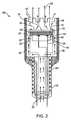
図2に示されるように、遠位チップアセンブリ48は、好ましくはエネルギー源12に連結されたハウジング16を含む。ハウジングは、好ましくは開放ハウジング16であるが、代わりにエネルギー源12を囲む閉鎖端ハウジングであり得る。閉鎖端ハウジングの少なくとも一部分は、エネルギービーム20に対して透明である材料から作られる。材料は、好ましくは超音波エネルギーに対して透明であるポリ4−メチル、1−ペンテン(PMP)材料など、または任意の他の適切な材料である。ハウジングは、好ましくは長方形または楕円形の断面を有し、その結果、少なくとも1つの辺は隣接する辺より長いが、代わりに、円形など任意の他の適切な断面を有し得る。図2に示されるように、開放の管状ハウジングは、好ましくは複数のスロット52を規定する「城上部」構成を有する。スロット52は、流れる流体またはゲル28のための出口ポートを提供するように機能を果たす。エネルギー送達システム10の使用中に、遠位チップアセンブリ48の前部チップが組織276または他の構造に接触するかまたは隣接するとき、スロット52は、エネルギー源12を通過し、組織276の表面に沿って冷却流体28の流れを維持するように機能を果たす。閉鎖端ハウジングにおいて、ハウジングは、ハウジング16の遠位端の方への小さな穴などの複数のアパーチャを規定する。これらの穴は、流れる流体またはゲルのための出口経路を提供する。アパーチャは、好ましくは、格子、ふるい、穴、ドリップ穴、水抜き構造または任意の多数の適切なアパーチャである。遠位チップアセンブリ48のハウジング16は、さらにエネルギー源12の面と組織276との間の障壁を提供するように機能を果たす。トランスデューサアセンブリはハンドピース内に引っ込んでいるので、ハンドピースの遠位端は皮膚表面に接触し得るが、トランスデューサアセンブリ自体は好ましくは皮膚に接触しない。 As shown in FIG. 2, the
エネルギー源。図1に示されるように、好ましい実施形態のエネルギー源12は、エネルギーの供給源を提供するように機能を果たし、エネルギービーム20を放出する。エネルギー源12は、好ましくは超音波ビームを放出する超音波トランスデューサであるが、代わりにエネルギーの任意の適切な供給源を提供するように機能を果たす任意の適切なエネルギーのエネルギー源であり得る。エネルギーのそのような適切な供給源は、無線周波数(RF)エネルギーと、マイクロ波と、フォトニックエネルギーと、熱エネルギーとを含み得る。療法は、代わりに冷却された流体(例えば、低温流体)を用いて達成され得る。エネルギー源およびデバイスは、外部電源によって電力を供給され得るか、または再充電可能電池または再充電不可電池によって動作され得る。 Energy source. As shown in FIG. 1, the
超音波トランスデューサは、好ましくはPZT(ジルコン酸チタン酸鉛)またはPVDF(ポリフッ化ビニリデン(polyvinylidine difluoride))などの圧電気材料、または任意の他の適切な超音波ビーム放出材料から作られる。そのような適切なトランスデューサコーティング金属は、金、ステンレス鋼、ニッケルカドミウム、銀、または金属合金を含み得る。エネルギー源12は、好ましくはいくつかの変種のうちの1つである。図2に示されるように第1の変種において、エネルギー源12は、平らな前面を有するディスクである。エネルギー源12のこの平らな前面は、代わりに、レンズの効果を達成するために凹面または凸面のいずれかであり得る。ディスクは、好ましくは円形の外形を有するが、代わりに、楕円形、多角形、ドーナツ形、または任意の他の適切な形状であり得る。さらに、エネルギー源12の異なる部分または異なるエネルギー源12は各々、異なるモード、周波数、時間の長さ、電圧、衝撃係数、出力、または適切な特性において動作され得る。 The ultrasonic transducer is preferably made from a piezoelectric material such as PZT (lead zirconate titanate) or PVDF (polyvinylidene fluoride), or any other suitable ultrasonic beam emitting material. Such suitable transducer coating metals can include gold, stainless steel, nickel cadmium, silver, or metal alloys. The
図2に示されるように、エネルギー源12の前面は、好ましくは整合層34に連結される。整合層は、好ましくはエネルギー源12の前面をカバーする。整合層34は、エネルギービーム20を周囲の流体28に連結する効率を上げるように機能を果たす。例えば、エネルギー源12が超音波トランスデューサである場合、超音波エネルギーがエネルギー源12から流体28の中に動くと、音響インピーダンスは、2つの媒体において異なり、結果として、超音波エネルギーの一部は、反射してエネルギー源12に戻る。整合層34は、音反射が最小限になるように中間インピーダンスの経路を提供し、エネルギー源12から流体28への出力音は最大限にされる。整合層34の厚さは、好ましくは整合層材料における音波の波長の長さの4分の1である。整合層は、好ましくはパリレンなどのプラスチック材料から作られ、好ましくは蒸着技術によってトランスデューサ面に配置されるが、代わりに、任意の適切な方法でトランスデューサに追加される、グラファイトまたはセラミックなどの任意の適切な材料であり得る。さらに、エネルギー源12は、エネルギー源12から流体28の中への最大のエネルギー伝達を達成するために、トランスデューサの面に概して2つまたは3つである複数の整合を含み得る。 As shown in FIG. 2, the front surface of the
図2に示されるように、好ましい実施形態のエネルギー送達システム10はまた、エネルギー源12に連結されるバッキング22を含む。エネルギー源12は、好ましくは接着リング24によってバッキング22の端部に結合される。バッキング22は好ましくは金属またはプラスチックから作られ、その結果、バッキング22は、エネルギー源12のためのヒートシンクを提供する。エネルギー源12は、エネルギー源12の後面とバッキング22との間にポケットが存在するように、バッキング22に取り付けられる。ポケットは、好ましくはいくつかの変種のうちの1つである。第1のバージョンにおいて、バッキング22は、複数の点においてエネルギー源に連結する。例えば、バッキングは、好ましくは、エネルギー源12の大部分が好ましくはバッキングの一部分に触れないように、外側部分に連結する3つのポストを含む。この変種において、流体またはゲルは、エネルギー源12を通って流れ、好ましくはエネルギー源12の前面および後面の両方を浸す。第2の変種において、ポケットは、エネルギー源12の後面とバッキング22との間のエアポケット26である。エアポケット26は、エネルギー源12が電気エネルギーの印加によって電力を通されると、放出されたエネルギービーム20がエアポケット26によって反射させられ、エネルギー源12から外に向けられるように、機能を果たす。バッキング22は、好ましくは円筒形のエアポケットを規定し、より好ましくは、環状の形状を有するエアポケットを規定する。バッキングは、バッキングが断面で見ると実質的に三脚の形状を有するように、中心ポストをさらに含むことによって環状のエアポケットを規定し、この場合、バッキングは、エネルギー源の外側部分およびエネルギー源の中心部分の両方の方に向かってエネルギー源12に連結される。エアポケット26は、代わりに、エネルギービーム20の実質的な部分がエネルギー源12から外側に向けられように任意の他の適切な材料によって取り替えられ得る。 As shown in FIG. 2, the preferred embodiment
冷却機構。好ましい実施形態の冷却機構は、エネルギー源12および/または組織276を冷却するように機能を果たす。冷却機構は、エネルギー源が、電力を通され、エネルギービーム20を放出している間に熱くなり得るエネルギー源12の温度を、最適な動作温度範囲内にエネルギー源12の温度を維持するように機能を果たす。エネルギー源12の冷却は、好ましくはエネルギー源12の温度より低い温度を有する、例えば食塩水などの流体または任意の他の生理的適合流体にエネルギー源12を接触させることによって達成される。流体またはゲルの温度は、好ましくは−5℃〜5℃であり、より好ましくは、実質的に0℃に等しい。流体は、代わりにエネルギー源12を十分に冷却する任意の適切な温度であり得る。冷却機構は、組織の外側層を加熱することを防ぐように機能を果たし、エネルギー送達システム10が組織の外側層を実質的に損傷することを防ぐように機能を果たす。冷却機構は、好ましくはいくつかの変種のうちの1つである。 Cooling mechanism. The cooling mechanism of the preferred embodiment functions to cool the
図2に示されるように、第1の変種において、冷却機構はバッキング22を含み、バッキング22は、好ましくはバッキング22の外側表面に沿って長手方向に配置される一連の溝36を有し、一連の溝36は、バッキング22の外側表面に実質的に沿って冷却流体28が流れることを可能にし、エネルギー源12の面を通過するように機能を果たす。一連の溝は、代わりに、らせん状などの任意の他の適切な構成でバッキングに沿って配置され得る。結果として生じる流体の流れ線は、図2において30として描かれる。冷却流体の流れは、内腔32を通って達成される。流体の流れ線30は、バッキング22における溝に沿って流れ、エネルギー源12を浸し、流体柱を形成し、城上部ハウジング16におけるスロットを通って出る。トランスデューサを冷却するために用いられる流体は、好ましくは、ハウジング16の端部を通るかまたは1つ以上のアパーチャを通ってハウジング16から出る。アパーチャは、好ましくは、格子、ふるい、穴、ドリップ穴、水抜き構造または任意の多数の適切なアパーチャである。流体は、代わりに、任意の他の適切な方法でエネルギー源12を通過して流れ得、エネルギー源12を浸し得る。図1に示されるように、流体28は、好ましくは流体柱を形成し、ハウジング16を出て、標的組織276と接触し、組織を冷却する。 As shown in FIG. 2, in the first variant, the cooling mechanism includes a
第2の変種において、冷却機構は、冷却ゲルまたはゼリーを含む。冷却ゲルは、好ましくは、エネルギービーム20を組織に適用する前に組織に適用される。冷却ゲルは、好ましくは、一度エネルギービームが組織に適用されても外側層に損傷が生じないように、組織の外側層を冷却する。代わりに、冷却ゲルは、エネルギー送達システム10を使用中、組織に適用され得、好ましくは、エネルギービームが適用されている間、組織の外側層を冷却する。さらに、冷却ゲルは、エネルギー源12と患者との間にエネルギービーム20を連結するようにさらに機能を果し得る。 In the second variant, the cooling mechanism comprises a cooling gel or jelly. The cooling gel is preferably applied to the tissue prior to applying the
第3の変種において、冷却機構は、凍結剤スプレーを含む。凍結剤スプレーは、好ましくは液体窒素などの冷却物質であるが、代わりに、接触冷却によって組織を冷却する任意の他の冷却スプレーであり得る。凍結剤スプレーは、好ましくは、エネルギービーム20を組織に適用する前に組織に適用される。凍結剤スプレーは、好ましくは、一度エネルギービームが組織に適用されても外側層に損傷が生じないように、組織の外側層を冷却する。代わりに、凍結剤スプレーは、エネルギー送達システム10を使用中、組織に適用され得、好ましくは、エネルギービームが適用されている間、組織の外側層を冷却する。 In the third variant, the cooling mechanism comprises a cryogen spray. The cryogen spray is preferably a cooling material such as liquid nitrogen, but may alternatively be any other cooling spray that cools the tissue by contact cooling. A cryogen spray is preferably applied to the tissue prior to applying the
冷却機構は、好ましくは、これらの変種のうちの1つであるが、冷却機構は、エネルギー源12および/または組織276を冷却する機能を果たす任意の他の適切なデバイスまたは物質であり得る。 The cooling mechanism is preferably one of these variants, but the cooling mechanism may be any other suitable device or material that serves to cool the
エネルギービームと組織との相互作用。電気的パルスまたはパルス列よって電力を通された場合、エネルギー源12は、エネルギービーム20(音波など)を放出する。エネルギービーム20の特性は、エネルギー源12、整合層34、バッキング22、および電気的パルスの特性によって決定される。これらの要素は、組織の中に伝達されるエネルギービーム20(音波など)の周波数、帯域幅、および振幅を決定する。図3に示されるように、エネルギー源12は、エネルギービーム20が組織276と相互に作用し、療法帯278を形成するように、エネルギービーム20を放出する。例えば、以下に説明されるように、エネルギービーム20は超音波ビームである。組織276は、好ましくは、視準長L内のエネルギービーム20に提示される。組織276の前面280は、ハウジング16の面から距離d(282)だけ離れている。エネルギービーム20が組織276を通って伝わると、エネルギービーム20のエネルギーは、組織276によって吸収され、熱エネルギーに変換される。この熱エネルギーは、周囲組織よりも高い温度に組織を加熱し、結果として、加熱帯278をもたらす。 Interaction of energy beam with tissue. When powered by an electrical pulse or pulse train, the
エネルギービーム20は、好ましくは、いくつかの変種のうちの1つにおいて組織に適用される。エネルギービーム20は、好ましくは、エネルギービーム20が真皮および/または皮下層などの表皮の下の内側層と相互に作用し、外側層が損傷されないままであるように、皮膚に適用される。第1の変種において、エネルギービーム20は、皮膚の内側層内に位置を定められるコラーゲンと相互に作用する。自然の加齢プロセス、UV線への曝露などの間中、コラーゲンは退化し、ばらばらになり、このことは、皮膚の引き締まりを少なくし、しわの形成となる。エネルギービーム20がコラーゲンと相互に作用する場合、エネルギービーム20は、好ましくはコラーゲンが、しわを硬直させかつ/またはしわを収縮させ、しわの外見を最小限にするように、コラーゲンを加熱する。さらに、コラーゲンを加熱することは、皮膚の層の自然の治癒プロセスを始めるように皮膚の層を促し、それによって新コラーゲンの成長を誘引する。この変種において、エネルギービーム20の深さは、好ましくは、コラーゲン層の実質的に下にある脂肪層が好ましくは無傷であり、エネルギービーム20によって影響されないままであるように制御される。 The
第2の変種において、エネルギービーム20は、皮膚の外側層の下に位置を定められる脂肪組織と相互に作用する。この変種は、好ましくは、脂肪組織を変化させ、従来の脂肪吸引法の臨床結果と実質的に同様の臨床結果を達成するように機能を果す。第1のバージョンにおいて、エネルギービームは、脂肪組織を破壊しかつ/または液化し、患者から脂肪細胞を除去する。第2のバージョンにおいて、エネルギービーム20は、脂肪室の大きさを収縮させ、脂肪の外見を減少させ得るように機能を果たす。第3の変種において、エネルギービーム20は、激しいアクネを引き起こす汗孔の皮脂生成腺(oil dispensing gland)と相互に作用し、汗孔の皮脂生成腺を破壊する。 In the second variant, the
第4の変種において、エネルギービーム20は、心臓組織と相互に作用する。心臓組織は、好ましくは、心臓内組織などの心臓の室または脈管の内部組織である。エネルギービーム20は、好ましくは、心臓内表面が完全に未損傷のままであるように、下部層(非表面層など)と相互に作用する。 In the fourth variant, the
第5の変種において、エネルギービーム20は、末梢静脈、好ましくは拡張蛇行静脈と相互に作用する。システムは、治療されるべき静脈の上の皮膚の表面に対して位置を決められるが、代わりに、静脈の中に挿入され得る。エネルギービーム20が皮膚の表面下の静脈と相互に作用する場合、静脈は加熱され、好ましくは、結果として関係する静脈の閉鎖をもたらす。 In the fifth variant, the
エネルギービーム20は、好ましくはこれらの変種のうちの1つにおいて組織に適用されるが、エネルギービームは、任意の他の適切な療法または治療のために任意の他の適切な方法で組織に適用され得る。治療され得る他の組織は、管腔組織と、表面下の治療が所望される組織とを含むが、これらに限定されない。 The
療法帯の物理的特性。エネルギービーム20によって形成される療法帯278の形状は、エネルギービーム20、エネルギー源12(材料、外形、電力を通されかつ/または電力を通されないエネルギー源12の部分などを含む)、整合層34、バッキング22(以下に説明される)、電気アタッチメント14、14’からの電気パルス(周波数、電圧、衝撃係数、パルス長などを含む)、ビーム20が接触する標的組織の特性および接触時間またはドウェル時間の長さなどの適切な組み合わせ要因の特性に依存する。ワイヤ38、38’および38”は、電池または壁差し込み口などの電源(図示されていない)からエネルギー源12に電気エネルギーを運ぶ。 The physical characteristics of the therapy zone. The shape of the
エネルギービーム20によって形成される療法帯278の形状は、好ましくは、いくつかの変種のうちの1つである。図3に示されるように、第1の変種において、帯278の直径D1は、組織表面280の近くにおいてビーム20の直径Dより小さく、組織276の外側層276’は、実質的に未損傷のままである。直径の変更および外側層の節約は、組織276の外側層276’を冷却するように機能を果たす冷却機構(組織表面280を通過して流れる、図1に示されるような冷却流体28など)によって提供される熱冷却による。組織276’の外側層は、多かれ少なかれ、組織表面280が冷却される量および/またはエネルギー源12、エネルギービーム20などの特性のために、節約され得るかまたは実質的に未損傷のままであり得る。 The shape of the
エネルギービーム20が組織の中により深く進むと、表面の熱冷却ほど効率的ではない熱冷却が周囲組織によって提供される。結果として、療法帯278は、周囲組織の熱移動特性ならびにビーム20からのエネルギーの継続する入力によって決定されるように、D1より大きい直径D2を有する。ビーム20が長期間にわたり組織に向けられると、療法帯278は組織の中に広がるが、無限にではない。超音波エネルギーの減衰、健康な周囲組織によって提供される熱移動、および視準長Lを超えるビームの発散などの要因によって決定されるように、療法帯278の深さ288の自然の限界がある。この超音波と組織との相互作用中、超音波エネルギーは組織によって吸収され、従って、超音波エネルギーが組織の中にさらに深く進むことが一層可能ではなくなる。従って、組織において対応するより小さい直径の加熱帯が発達させられ、全体の結果として、加熱された療法帯278が形成され、加熱された療法帯278は、組織の中の深さ288に限定された細長い涙のしずく形である。 As the
療法帯278の形状は、好ましくはいくつかの変種のうちの1つであるが、療法帯278の形状は、任意の適切な形状で組織内の任意の適切な深さであり得、エネルギービーム20と、エネルギー源12(材料、外形などを含む)、整合層34と、バッキング22と、電気パルス(周波数、電圧、衝撃係数、パルス長などを含む)と、冷却機構と、ビーム20が接触する標的組織276と、接触時間またはドウェル時間の長さとの任意の適切な組み合わせによる任意の適切な態様で変化させられ得る。 The shape of the
追加の要素。図1に示されるように、好ましい実施形態のエネルギー送達システム10はまた、遠位チップアセンブリ48に連結された細長い部材18を含む。好ましい実施形態の細長い部材18は、遠位チップアセンブリ48とハンドル50とを有するシャフトである。細長い部材18は、好ましくは、遠位チップアセンブリ48にハンドル50を連結し、その結果、遠位チップアセンブリ48(および/またはエネルギー源12)は、組織276の表面に沿って動かされる。シャフトは、たわみ軸(flexible shaft)であり、その結果、シャフトは曲げられ、所望の構成に位置を決められる。シャフトは、好ましくは、再度曲げられるかまたは代替の所望の構成に再度位置を決められるまで、所望の構成のままである。細長い部材18は、様々な位置に細長い部材18を曲げるかまたは位置を決めるように(図1に示されるように、組織276の方に細長い部材18の遠位部分を曲げるなど)機能を果たす曲げ機構をさらに含み得る。曲げ機構は、好ましくは、複数本のワイヤ、リボン、ケーブル、ひも、繊維、フィラメントまたは任意の他の引張り部材を含む。代わりに、細長い部材18は、固定もしくは剛体のシャフトまたはグーズネック型シャフトなどの任意の他の適切なシャフトであり得、グーズネック型シャフトは、シャフトを曲げ、シャフトの位置を決めるために互いに対して動き、軸方向に整列させられる複数の部分を含む。シャフトは、好ましくは複数内腔管(multi−lumen tube)であるが、代わりに、カテーテル、カニューレ、管、または1つ以上の内腔を有する任意の他の適切な細長い構造であり得る。好ましい実施形態の細長い部材18は、プルワイヤ、流体、気体、エネルギー送達構造、電気的接続、および/または任意の適切なデバイスまたは要素を収容するように機能を果たす。 Additional elements. As shown in FIG. 1, the
図1に示されるように、好ましい実施形態のエネルギー送達システム10はまた、細長い部材18の近位部分にハンドル50を含む。ハンドル50は、オペレータおよび/またはモータ駆動ユニットがシステム10に連結する部分を提供するように機能を果たす。ハンドル50は、好ましくは、ハンドル50を保持するオペレータによって保持され、動かされるが、代わりに、ハンドル50はモータ駆動ユニットに連結され、動作は好ましくはコンピュータ制御の動作である。ハンドル50は、代わりに、任意の他の適切な態様で連結され、動かされ得る。ハンドヘルドシステム10のハンドル50に連結されていると、オペレータおよび/またはモータ駆動ユニットは、組織276の表面に沿って遠位チップアセンブリ48および/またはエネルギー源12動かす。遠位チップアセンブリ48および遠位チップアセンブリ48内のエネルギー源12は、好ましくは、遠位チップアセンブリ48が放出されたエネルギービーム20をエネルギー源12から組織276に向け、エネルギービーム20が適切な角度で標的組織276に接触するように、患者内において動かされ、位置を決められる。オペレータおよび/またはモータ駆動ユニットは、好ましくは、筆記面を横切ってペンを動かすことと同様に、療法経路に沿ってエネルギー送達システム10を動かし、エネルギー源12が療法経路に沿って部分的または全体の加熱帯を提供するように、エネルギー源12に電力を通し、エネルギービーム20を放出する。療法経路に沿った、加熱帯は、好ましくは、療法を提供するために任意に適切な形状を有する。療法経路に沿った加熱帯は、代わりに患者のための任意の他の適切な療法を提供し得る。ハンドル50は、モータ駆動ユニットに取り外し可能に連結され得るか、または代わりにモータ駆動ユニットに直接一体化され得る。 As shown in FIG. 1, the
ハンドル50は、好ましくはいくつかの変種のうちの1つである。第1の変種において、図1に示されるように、ハンドル50は、細長い部材18の隆起した部分であり、代わりに、ハンドル50は、単に、オペレータによって保持される細長い部材18の近位部分であり得る。ハンドル50は、さらに、指用凹部または任意の他の適切な人間工学的グリップ外形を含み得る。ハンドルは、好ましくは、ゴム、発泡樹脂製品、またはプラスチックなどの高摩擦係数を有する材料から作られ、その結果、ハンドル50はオペレータの手から滑らない。ハンドル50は、ダイヤル、ボタン、および出力ディスプレイなどの制御装置をさらに含み得、その結果、オペレータは、エネルギー源12、エネルギー源12の位置、冷却機構、センサ(下記に説明される)、曲げ機構、および/またはハンドヘルドシステム10のデバイスの任意の他の適切な要素を制御し得る。 The handle 50 is preferably one of several variants. In the first variant, as shown in FIG. 1, the handle 50 is a raised portion of the
好ましい実施形態の遠位チップアセンブリ48はまた、間隙(すなわち、エネルギー源12からの組織表面の距離)と、組織276の厚さと、治療した組織の特性と、組織の様々な深さの各々における温度と、任意の他の適切なパラメータまたは特性とを検出するように機能を果たすセンサを含む。 The
センサは、超音波トランスデューサであるが、代わりに、IRセンサ、温度計など、任意の適切なパラメータまたは特性を検出する任意の適切なセンサであり得る。超音波トランスデューサは、好ましくは、概して組織を加熱するのに十分ではない短い持続時間の超音波のパルスを利用する。これは、当該分野においてAモードまたは振幅モード画像化と呼ばれる単純な超音波画像化技術である。センサは、好ましくは、異なるモード(Aモードなど)で動作する、エネルギー源のトランスデューサと同じトランスデューサであるか、または別個の超音波トランスデューサであり得る。間隙(例えば、トランスデューサと組織表面との間の距離)、療法の標的である組織の厚さ、組織の様々な深さの各々における温度、および加熱された組織の特性についての情報を検出することによって、センサは、好ましくは、ハンドヘルドシステムの位置を決める場所について、適切な間隙距離を維持するために遠位チップアセンブリに対してエネルギー源をどの位置で有し、エネルギー源12および任意の他の適切な要素のどれを用いるかにおけるどの設定において、組織の加熱によって提供される療法を導き、オペレータおよび/またはモータ駆動ユニットを導くように機能を果たす。間隙距離は、好ましくは0mm〜20mmであり、より好ましくは10mm〜15mmである。 The sensor is an ultrasonic transducer, but may instead be any suitable sensor that detects any suitable parameter or characteristic, such as an IR sensor, thermometer, etc. The ultrasound transducer preferably utilizes short duration ultrasound pulses that are generally not sufficient to heat the tissue. This is a simple ultrasound imaging technique referred to in the art as A-mode or amplitude mode imaging. The sensor is preferably the same transducer as the energy source transducer operating in a different mode (such as A mode) or may be a separate ultrasonic transducer. Detecting information about gaps (eg, the distance between the transducer and the tissue surface), the thickness of the tissue that is the target of therapy, the temperature at each of the various depths of the tissue, and the properties of the heated tissue By which the sensor preferably has an energy source relative to the distal tip assembly in order to maintain an appropriate gap distance for where the handheld system is located, and the
簡潔さのために省略されているが、好ましい実施形態は、様々なエネルギー源12、電気的アタッチメント14、14’のエネルギービーム20、センサ40、およびプロセッサのあらゆる組み合わせおよび入れ替えを含む。さらに、本明細書において開示される他の特徴はまた、前に説明された実施形態において用いられ得る。 Although omitted for brevity, preferred embodiments include any combination and replacement of
図4は、超音波ベース治療デバイスの別の例示的実施形態を示し、その超音波ベース治療デバイスは、皮下脂肪層などの周囲のそして下にある皮膚構造に実質的な損傷を与えることなく、約40℃〜90℃、より特定的には45℃〜80℃、そして好ましい実施形態においては、50℃〜75℃の局所の熱治療を提供することによって結合性組織を治療するように構成される。そのような熱治療の後に、標的組織深さ内のコラーゲン繊維は、その有力な方向に沿って収縮し、組織の硬直を生成する。 FIG. 4 illustrates another exemplary embodiment of an ultrasound-based treatment device that does not substantially damage surrounding and underlying skin structures, such as the subcutaneous fat layer, Configured to treat connective tissue by providing local thermal treatment at about 40 ° C. to 90 ° C., more particularly 45 ° C. to 80 ° C., and in a preferred embodiment, 50 ° C. to 75 ° C. The After such thermal treatment, collagen fibers within the target tissue depth contract along their dominant direction, creating tissue stiffness.
デバイスは、上皮組織界面における温度およびオプションで組織の中のより深いところにおける温度の制御レベルを維持するために温度制御アセンブリを備えている。デバイスは、超音波エネルギーを組織に送達する超音波トランスデューサアセンブリと、冷却アセンブリが組織表面温度を制御し、超音波アセンブリが超音波エネルギーを組織の中に送達すると、ユーザまたはデバイスオペレータが皮膚表面に沿って均等にデバイスを動かすことを可能にするハンドピースとをさらに備えている。デバイスは、外部電源によって、または再充電可能バッテリまたは再充電不可バッテリなどの内部電源によって電力を供給され得る。 The device includes a temperature control assembly to maintain a controlled level of temperature at the epithelial tissue interface and optionally deeper in the tissue. The device includes an ultrasonic transducer assembly that delivers ultrasonic energy to the tissue, a cooling assembly that controls the tissue surface temperature, and the ultrasonic assembly delivers ultrasonic energy into the tissue so that the user or device operator can And a hand piece that allows the device to move evenly along. The device may be powered by an external power source or by an internal power source such as a rechargeable or non-rechargeable battery.
組織内の超音波ベースの熱エネルギー送達によってもたらされる治療帯の大きさおよび深さは、以下のパラメータのうちの1つ以上を調整することによって制御される。すなわち、組織表面温度、超音波周波数、超音波エネルギー密度、およびデバイスが皮膚表面に沿って動かされる速度である。 The size and depth of the treatment zone provided by ultrasound-based thermal energy delivery within the tissue is controlled by adjusting one or more of the following parameters. That is, the tissue surface temperature, the ultrasonic frequency, the ultrasonic energy density, and the speed at which the device is moved along the skin surface.
例示的実施形態に従って、図4は、局所の熱治療によって結合性組織を治療するように構成される超音波ベースの治療デバイス400の概略図を例示する。デバイス400は、ハンドピース401と、超音波トランスデューサアセンブリ402と、冷却アセンブリ403と、コントローラユニット404とを備えている。コントローラユニット404は、プログラマブルであり、トランスデューサアセンブリ402および冷却アセンブリ403の動作パラメータを調整することが可能である。さらに、前に上記に説明された任意の特徴は、以下に説明される実施形態において用いられ得る。 In accordance with an exemplary embodiment, FIG. 4 illustrates a schematic diagram of an ultrasound-based
デバイス400は、組織405の表面に沿って動かされるように構成される。デバイス400が組織405の表面に沿って動かされると、冷却アセンブリ403は、所望の温度レベルに組織405の表面を冷却し、一方、超音波トランスデューサアセンブリ402は組織405のある深さの中に超音波エネルギーを送達する。
超音波トランスデューサアセンブリ402は、組織層および標的領域を治療するように構成される。トランスデューサは、超音波ビームを形作るために1つ以上のレンズをオプションで備え得る。トランスデューサは、ジルコン酸チタン酸鉛(PZT)などの圧電気活性材料、または、圧電気セラミック、水晶、プラスチック、および/もしくは合成材料などの任意の他の圧電気活性材料、ならびに、ニオブ酸リチウム、チタン酸鉛、チタン酸バリウムおよび/もしくはメタニオブ酸鉛を備え得る。圧電気活性材料の他にまたは圧電気活性材料の代わりに、トランスデューサは、放射線および/または音響エネルギーを生成するように構成される任意の他の材料を備え得る。 The
オプションで、超音波トランスデューサアセンブリ402はデバイス400に交換可能に取り付けられ得、例えば超音波周波数およびエネルギー密度などのデバイスパラメータを変更することを可能にし、それによって様々な交換可能超音波トランスデューサアセンブリ402のうちの1つを用いることによって治療を変更し得る。オプションで、そのような交換可能に取り付けられた超音波トランスデューサアセンブリ402は、使い捨て可能であり得る。オプションで、デバイス400は、使い捨て可能ユニットに付着するように構成され得、この場合、使い捨て可能ユニットは、薬用化粧品、計量分配薬、保湿因子、皮膚細胞新生因子などのスキンケア物質を計量分配する。 Optionally, the
一実施形態において、トランスデューサアセンブリ402は、単一のトランスデューサを含む。トランスデューサは、図5Aに示されるように円形またはディスク様の形状502a、図5Bに示されるように長方形または正方形の形状502b、または図5Cに示されるようにリングもしくは環状の形状502cを含み得る。トランスデューサの形状は、トランスデューサによって生成される超音波ビームの形状に影響及ぼし、超音波ビームの形状は、次に治療帯の形状に影響を及ぼす。そのような形状の例は、以下にさらに説明される。 In one embodiment,
オプションで、トランスデューサアセンブリ402は、整列して配置される複数のトランスデューサを含み得、トランスデューサアセンブリ402の表面が冷えたままであるような方法で超音波エネルギーを送達し、かつ/または、デバイス400が動かされると、より大きい列を達成し得る。円形504dまたは長方形504eのトランスデューサを含む例示の整列は、それぞれ図5D−図5Eに示される。円形504f’および長方形504f”のトランスデューサの混合を含む例示の整列は、図5Fに示される。複数のトランスデューサは、所望の治療帯を確立するために、別個にもしくは一緒に、または様々な組み合わせで活性化され得る。 Optionally, the
デバイス400は、アセンブリに電気エネルギーを提供するように構成される1つ以上の電源を含み得る。感知デバイスは、安全の目的のために備えつけられ得、トランスデューサアセンブリ402において1つ以上の増幅器またはドライバが必要とする電力を含む、アセンブリに送達される出力のレベルを監視し得る。電源構成要素は、フィルタリング構成を含み得、駆動の効率および有効性を増加させ得る。代わりに、電力は、電気ケーブルまたは他の適切な手段を介して外部からデバイスに加えられ得る。
図4は、ハウジング内に冷却アセンブリ403を含むデバイス400を示す。容易に理解され得るように、冷却アセンブリは、デバイス400に取り外し可能に取り付け可能な別個のユニットとしてハウジング外にあり得る。オプションで、冷却アセンブリ403は、図5Gに示されるように、トランスデューサアセンブリ402の一体化した部分であり得、トランスデューサの周りそしてトランスデューサと皮膚との界面に冷気を提供し得る。 FIG. 4 shows a
図6は、トランスデューサ402が電気エネルギーを受信し、超音波エネルギーのビーム601を放出したときのトランスデューサ402を示す。超音波がトランスデューサアセンブリ402によって放出されたときの超音波の典型的なビームパターンが示され、そのビームパターンは、音圧がビームの中線に対して約6デシベル(dB)だけ降下する場所をマッピングすることによって超音波ビーム601の輪郭を例示する。ビーム601は、概して視準的態様でLの距離まで伝わり、その後発散し、超音波ビーム601の原点において直径がトランスデューサアセンブリ402の直径Dにおおよそ一致する。デバイス400が平らなディスクトランスデューサの自然な集束に頼る場合、超音波ビーム601は、ほぼLの深さまで集束し、Lの深さを超えるとビームは発散する。最小限のビーム幅D’は、距離Lにおいて生じる。距離Lは、トランスデューサの直径(例えば、トランスデューサディスクの直径)および超音波周波数によって決定される。ビーム601の挙動についてのさらなる詳細およびトランスデューサアセンブリ402を構成することは(様々なタイプのトランスデューサまたはトランスデューサ整列を用いて、音響レンズを用いてなど)、本出願と同一の発明者および譲受人を有する、同時係属中の米国特許出願公開第2007/0265609号に説明される。 FIG. 6 shows the
なおも図6を参照すると、デバイス400に関して、Lが治療帯の大きさまたは体積を確立するので比較的大きいLが所望され、従って、所定のデバイス直径に対してDが最大にされ、その結果、Lは次に最大にされる。より高い超音波周波数は距離Lを増加させ、超音波は増加する超音波周波数と共に組織105においてより多く減衰させられるので、治療帯の所望の深さは、超音波の使用可能な最大周波数を決定する。デバイスサイズおよび超音波減衰の制約がある場合、本デバイスは、例えば、約12MHzの動作周波数および約2.5mmのディスク直径を用い得、結果として、約12mmの深さLおよび約1.6mmの最小ビーム幅D’となる。 Still referring to FIG. 6, for
図7は、超音波ビームの組織との相互作用を示す。組織405は、視準長さL内で超音波ビーム601に提示される。超音波ビームは、組織405を介して伝わり、超音波ビーム601のエネルギーは、組織405によって吸収され、周囲の組織より高い温度に組織を加熱する熱エネルギーに変換される。結果として、デバイス400の面から距離dだけ離れ、組織405の表面下から始まる細長い涙のしずくの典型的な形状を有する長さ702の加熱された治療帯701となる。加熱された治療帯701を形作る組織熱移動特性についてのさらなる詳細は、上記に参照された米国特許出願公開第2007/0265609号に説明される。上記に説明されるように、トランスデューサの形状は治療帯の形状に影響を及ぼし、図7A〜図7Bは2つのこの例を示す。図7Aは、ディスク形のトランスデューサによって生成されるように細長い涙のしずく形の治療帯701を示し、一方、図7Bは、リング形のトランスデューサによって生成されるように細長さのより少ない歯形の治療帯701を示す。他のトランスデューサ形状は、さらに異なる形状の治療帯を生成し得る。異なるトランスデューサ形状を用いることによって、オペレータは、治療帯を適切に形作り、それによって、脂肪層または神経組織などの組織の選択可能な部分が熱損傷を受けるのを避けることが可能である。 FIG. 7 shows the interaction of the ultrasound beam with the tissue.
上記のように、適切な深さ、分布、タイミングおよびエネルギー密度で超音波エネルギーを送達することは、組織405への局所的熱エネルギー送達の所望の療法効果を達成するために、デバイス400のパラメータを調整することによって提供される。従って、デバイス400のパラメータは、例えば、特定の標的領域の深さおよび形状によって規定されるように、組織405内の対象とする特定の領域を標的にするように有利に調整され得る。そのような標的領域は、筋膜内などの組織の特定の層内に実質的にすっかり存在するか、または皮膚、真皮、脂肪(fat)/脂肪(adipose)組織、筋膜、懸垂組織、または筋肉などの組織層の組み合わせを横断し得る。発明者らはここで、デバイス400の様々なパラメータをさらに詳細に説明することにする。 As described above, delivering ultrasonic energy at the appropriate depth, distribution, timing and energy density is a parameter of
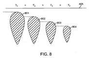
組織表面温度。超音波ベースの治療デバイス100の1つのパラメータは、局所の組織表面温度である。概して局所の組織表面温度を下げることは、組織表面下のより大きい深さに治療帯が作られるようにする傾向があり、一方逆に、温度を上げることは、より小さい深さに治療帯が作られるようにする傾向がある。これは、図8に図式に示され、この場合、一連の下降する表面温度T1>T2>T3>T4は、結果として、治療帯801、802、803および804を減少させる。従って、上皮の治療深さを調整する一つの方法は、冷却アセンブリ403によって制御され、維持されるように、局所の組織表面温度を修正することによる。 Tissue surface temperature. One parameter of the ultrasound-based treatment device 100 is the local tissue surface temperature. In general, lowering the local tissue surface temperature tends to allow a treatment zone to be created at a greater depth below the tissue surface, while increasing the temperature conversely reduces the treatment zone to a lower depth. There is a tendency to make it. This is shown schematically in FIG. 8, where a series of descending surface temperatures T1> T2> T3> T4 results in a decrease in
一実施形態において、冷却アセンブリ403は、金属板などの高伝導物質を含み、この高伝導物質は、組織405から離れるように熱を移動させ、それによって、組織を冷却する。別の実施形態において、冷却アセンブリ403は、組織405の表面に冷却液をスプレーするように構成され、それによって、組織405を冷却する。別の実施形態において冷却アセンブリ403は、組織405から熱を除去するために、周囲から熱を吸収し、その結果、相転移を受ける冷却された流体もしくはゲルまたは類似の物質の流れを用いる。さらに別の実施形態において、冷却アセンブリ403は、組織405を選択可能に冷却するペルチエ冷却デバイスまたはトムソン冷却デバイスを含む。別の実施形態において、冷却アセンブリ403は、熱カップラとしてゲルまたは流体を用い、組織405から冷却アセンブリ403の中への熱の流れを増加させる。 In one embodiment, the cooling
一実施形態において、トランスデューサ402が超音波エネルギーを組織405の中に送達している間、周囲温度より低い約5℃〜10℃の局所の組織表面温度を維持するように構成される。冷却アセンブリ403は、好ましくは、局所の組織表面の温度プロフィルを監視し、所望の温度を維持するために冷却レベルを適切に調整する。 In one embodiment, the
一実施形態において、冷却アセンブリ403は、トランスデューサアセンブリ402の表面の表面温度を減少させるように構成され、それによって組織405の表面を冷却することを助ける。 In one embodiment, the cooling
超音波周波数。超音波ベースの治療デバイス400の第2のパラメータは、超音波ビームの周波数である。概して、超音波周波数を上げることによって、超音波エネルギーが組織405の中により速やかに吸収され、超音波エネルギーが組織405の表面のより近くに消散するようにし、この場合、超音波周波数を下げることによって、超音波エネルギーが組織405の中にさらに遠くに入り込み、より大きな深さで消散する。 Ultrasonic frequency. The second parameter of the ultrasound based
これは、図9に図式に示され、この場合、一連の下降する超音波周波数f1>f2>f3>f4は、結果として、治療深さ901、902、903および904を増加させる。従って、トランスデューサアセンブリ402によって生成される超音波周波数を修正することは、治療深さおよび治療帯の大きさを調整し、それによって、治療帯の位置を調整する別の方法を表す。一実施形態において、トランスデューサアセンブリ402は、療法用途のためにおおよそ1MHz〜400MHz、典型的には1MHz〜100MHzの範囲内の周波数で超音波エネルギーを送達するように構成される。 This is shown schematically in FIG. 9, where a series of descending ultrasonic frequencies f1> f2> f3> f4 results in an increase in
超音波エネルギー密度。超音波ベースの治療デバイス400の第3のパラメータは、超音波ビームによって送達されるような超音波エネルギー密度である。超音波エネルギー密度は、治療が行われる速度を決定する。ビーム幅の断面積で割った、トランスデューサアセンブリ402によって送達される音響出力は、単位時間当たりの出力密度またはエネルギー密度を決定する。超音波エネルギー密度を増加させることは、結果として、単位時間当たり組織に送達されるより大量の熱、従って、より大きい治療帯サイズをもたらし、一方、超音波エネルギー密度を減少させることは、結果として、より小さい治療帯サイズをもたらす。これは、図10に図式に示され、この場合、いくつかの治療帯が組織405に作られるが、これらの治療帯は、様々なレベルの超音波エネルギー密度を有し、エネルギー密度レベルE1<E2<E3<E4を増加させることが、結果として治療帯サイズ1001、1002、1003および1004を増加させることを示す。本発明において、有効音響出力は、0.3ワット〜>10ワットの範囲であり、対応する出力密度は3ワット/cm2〜>100ワット/cm2の範囲である。これらの出力密度は、治療帯において発現させられる。ビームが治療帯を越えて発散すると、出力密度は降下し、その結果、露光時間(time exposure)に関わらず、治療は行われない。一実施形態において、十分な出力によって、1〜10秒の治療時間は、十分なエネルギー密度を送達し、治療帯を発現させる。Ultrasonic energy density. The third parameter of the ultrasound based
皮膚表面に沿ったデバイスの動作。図11に示されるように、超音波治療デバイス400の第4のパラメータは、オペレータが皮膚405の表面に沿ってデバイス400を動かす速度である。概して、デバイス400は、治療を提供するために超音波ビーム601が標的領域を十分に加熱することを可能にするほど十分に遅い速度で動かされるべきである。同時にデバイス400は、現実的な時間制限内で治療処置を完了させるために所定の速度で組織を横切って動かされるべきである。その結果、オペレータが制御された方法および制御された速度で皮膚405の表面に沿ってデバイス400を動かすと、皮膚表面下の選ばれた深さに連続治療帯が作られる。これは図11に示され、この場合、デバイス400の指示された動作は、連続治療帯1101の形成を引き起こす。図11は組織405の表面に実質的に平行に延びる治療帯1101を示すが、組織405内の様々な深さを横切って延びる治療帯1101を生成することが可能であることに注意されたい。これは、治療中、そしてデバイス400が組織405の表面に沿って動くとき、デバイス400の1つ以上のパラメータを対応して修正することによって達成され得る。例えば、図12に示されるように、組織405の表面に対してある角度の治療帯1201を生成するために、表面は、デバイスの動きの方向に前進的により高い速度で冷却され得る。所望の治療帯を生成するために、デバイス400が、皮膚に沿って直線の態様で動かされ得るか、または円形もしくはジグザグの態様などの非直線の態様で動かされ得ることに注意されたい。さらに、皮膚に沿って手動でデバイス400を動かすことの代案として、デバイス400の動きは動力化され得る。 Device movement along the skin surface. As shown in FIG. 11, the fourth parameter of the
オプションで、デバイス400は、デバイス400が治療帯に対して過剰の熱送達を防ぐかまたは抑制し、それによって安全性の増加を提供するように動作するように構成され得る。1つのそのような実施形態において、デバイス400は、デバイス400が長時間組織表面上に静止したままである場合でさえ、治療帯を過剰に加熱しないレベルに超音波出力密度を制限する。一実施形態において、出力密度のそのような上限は、10〜100ワット/cm2、好ましくは、約20〜60ワット/cm2、より好ましくは約30〜50ワット/cm2に設定される。Optionally,
組織405内の治療帯への過剰な熱送達を防ぐかまたは抑制するための別のそのような実施形態において、デバイス400は、組織表面に対するデバイス400の動作を感知するように構成される。デバイス400が組織405の表面に沿って十分な速度で動いていないと決定した場合、デバイス400は、超音波エネルギー送達を減少させるかまたは止める。組織表面に対するデバイス400の動作を検出するために、デバイス400は、加速度計、エンコーダまたは他の位置/配向デバイスなどの様々な動作および/または位置センサを含み得る。一実施形態において、コンピュータがデバイス400への出力送達を制御する間、動作を検出するためにコンピュータマウスが用いられる。 In another such embodiment for preventing or suppressing excessive heat delivery to a treatment zone within
上記のパラメータを調整することによって、治療深さの空間制御は、約0mm〜15mmの深さの広範囲内、典型的な使用法のためのいくつかの別々の深さに適切に固定された範囲、例えば約0mm〜9mmの細かい範囲に限定された調整を有する範囲など様々な範囲において適切に調整され得る。代わりにまたは組み合わせてデバイス400の1つ以上のパラメータは、治療中に動態で調整され得る。 By adjusting the above parameters, the spatial control of the treatment depth can be appropriately fixed within a wide range of depths of about 0 mm to 15 mm, several separate depths for typical usage. For example, it can be appropriately adjusted in various ranges such as a range having an adjustment limited to a fine range of about 0 mm to 9 mm. Alternatively or in combination, one or more parameters of
上記は、本発明の好ましい実施形態の完全な説明であるが、様々な代案、修正、および均等物が用いられ得る。例えば、本明細書に説明される特徴は、必要に応じ、互いに交換可能であり得る。従って、上記の説明は、添付の特許請求の範囲によって規定される本発明の範囲を制限するものとしてとられるべきではない。 While the above is a complete description of the preferred embodiments of the invention, various alternatives, modifications, and equivalents may be used. For example, the features described herein can be interchanged with one another as needed. Therefore, the above description should not be taken as limiting the scope of the invention which is defined by the appended claims.
Claims (52)
Translated fromJapaneseオペレータの手に適合するように人間工学的に成形されたハンドピースと、
該ハンドピースの遠位端の近くのトランスデューサアセンブリであって、該トランスデューサアセンブリは、超音波エネルギーを該組織に送達するように適合されている、トランスデューサアセンブリと、
組織表面を選択可能に冷却する冷却アセンブリであって、該冷却アセンブリは該ハンドピースに連結される、冷却アセンブリと、
超音波エネルギー源に動作可能に接続されるコントローラと
を備え、
該コントローラおよび該トランスデューサアセンブリは、該ハンドピースが該皮膚表面に隣接して位置を決められるときに、該皮膚表面下の組織を治療するように構成されることによって、治療帯を囲む組織を熱で損傷することなく、該皮膚表面下の該治療帯を加熱する、デバイス。An ultrasound-based device that non-invasively treats tissue beneath the skin surface, the device comprising:
An ergonomically shaped handpiece to fit the operator's hand;
A transducer assembly near the distal end of the handpiece, the transducer assembly being adapted to deliver ultrasonic energy to the tissue;
A cooling assembly for selectively cooling a tissue surface, wherein the cooling assembly is coupled to the handpiece;
A controller operably connected to an ultrasonic energy source,
The controller and the transducer assembly are configured to treat tissue under the skin surface when the handpiece is positioned adjacent to the skin surface to heat tissue surrounding the treatment zone. Heating the treatment zone under the skin surface without damaging the device.
オペレータの手に適合するように人間工学的に成形されたハンドピースと、
該ハンドピースの遠位端の近くのトランスデューサアセンブリであって、該トランスデューサアセンブリは、超音波エネルギーを該組織に送達するように適合されている、トランスデューサアセンブリと、
組織表面を選択可能に冷却する冷却アセンブリであって、該冷却アセンブリは該ハンドピースに連結される、冷却アセンブリと、
超音波エネルギー源に動作可能に接続されるコントローラと
を備え、
該コントローラおよび該トランスデューサアセンブリは、該ハンドピースが該皮膚表面に隣接して位置を決められるとき、該トランスデューサアセンブリと該皮膚表面とが直接接触することなく該皮膚表面下の組織を治療するように構成されることによって、治療帯を囲む組織を熱で損傷することなく、該皮膚表面下の該治療帯を加熱する、デバイス。An ultrasound-based device that non-invasively treats tissue beneath the skin surface, the device comprising:
An ergonomically shaped handpiece to fit the operator's hand;
A transducer assembly near the distal end of the handpiece, the transducer assembly being adapted to deliver ultrasonic energy to the tissue;
A cooling assembly for selectively cooling a tissue surface, wherein the cooling assembly is coupled to the handpiece;
A controller operably connected to an ultrasonic energy source,
The controller and the transducer assembly are adapted to treat tissue under the skin surface without direct contact between the transducer assembly and the skin surface when the handpiece is positioned adjacent to the skin surface. A device that, by being configured, heats the treatment zone under the skin surface without damaging the tissue surrounding the treatment zone with heat.
該皮膚表面に隣接する超音波ベースの治療デバイスの位置を決めることであって、該治療デバイスは冷却アセンブリとトランスデューサアセンブリとを備えている、ことと、
該治療デバイスが該皮膚表面に隣接して配置されるとき、該皮膚表面を冷却することと、
該トランスデューサアセンブリと該皮膚表面とが直接に接触することなく、該皮膚の下の治療帯に超音波エネルギーを送達することによって、該治療帯を囲む組織を熱で損傷することなく該治療帯を加熱することと
を包含する、方法。A method of non-invasively treating tissue below the skin surface, the method comprising:
Locating an ultrasound-based treatment device adjacent to the skin surface, the treatment device comprising a cooling assembly and a transducer assembly;
Cooling the skin surface when the treatment device is positioned adjacent to the skin surface;
Delivering ultrasonic energy to the treatment zone under the skin without direct contact between the transducer assembly and the skin surface, thereby reducing the treatment zone without heat damaging the tissue surrounding the treatment zone. Heating. A method comprising: heating.
Applications Claiming Priority (3)
| Application Number | Priority Date | Filing Date | Title |
|---|---|---|---|
| US6137308P | 2008-06-13 | 2008-06-13 | |
| US61/061,373 | 2008-06-13 | ||
| PCT/US2009/047110WO2009152379A1 (en) | 2008-06-13 | 2009-06-11 | System and method for delivering energy to tissue |
Publications (1)
| Publication Number | Publication Date |
|---|---|
| JP2011524205Atrue JP2011524205A (en) | 2011-09-01 |
Family
ID=41415440
Family Applications (1)
| Application Number | Title | Priority Date | Filing Date |
|---|---|---|---|
| JP2011513707APendingJP2011524205A (en) | 2008-06-13 | 2009-06-11 | System and method for delivering energy to tissue |
Country Status (6)
| Country | Link |
|---|---|
| US (1) | US20090312693A1 (en) |
| EP (1) | EP2285334A4 (en) |
| JP (1) | JP2011524205A (en) |
| AU (1) | AU2009257395A1 (en) |
| CA (1) | CA2726349A1 (en) |
| WO (1) | WO2009152379A1 (en) |
Cited By (1)
| Publication number | Priority date | Publication date | Assignee | Title |
|---|---|---|---|---|
| WO2023244014A1 (en)* | 2022-06-14 | 2023-12-21 | 주식회사 제이시스메디칼 | Ultrasound generation device |
Families Citing this family (91)
| Publication number | Priority date | Publication date | Assignee | Title |
|---|---|---|---|---|
| US8241274B2 (en) | 2000-01-19 | 2012-08-14 | Medtronic, Inc. | Method for guiding a medical device |
| US7617005B2 (en) | 2002-04-08 | 2009-11-10 | Ardian, Inc. | Methods and apparatus for thermally-induced renal neuromodulation |
| US8150519B2 (en) | 2002-04-08 | 2012-04-03 | Ardian, Inc. | Methods and apparatus for bilateral renal neuromodulation |
| US20040082859A1 (en) | 2002-07-01 | 2004-04-29 | Alan Schaer | Method and apparatus employing ultrasound energy to treat body sphincters |
| US10864385B2 (en) | 2004-09-24 | 2020-12-15 | Guided Therapy Systems, Llc | Rejuvenating skin by heating tissue for cosmetic treatment of the face and body |
| US8444562B2 (en) | 2004-10-06 | 2013-05-21 | Guided Therapy Systems, Llc | System and method for treating muscle, tendon, ligament and cartilage tissue |
| US8535228B2 (en) | 2004-10-06 | 2013-09-17 | Guided Therapy Systems, Llc | Method and system for noninvasive face lifts and deep tissue tightening |
| US9694212B2 (en) | 2004-10-06 | 2017-07-04 | Guided Therapy Systems, Llc | Method and system for ultrasound treatment of skin |
| US11235179B2 (en) | 2004-10-06 | 2022-02-01 | Guided Therapy Systems, Llc | Energy based skin gland treatment |
| US9827449B2 (en) | 2004-10-06 | 2017-11-28 | Guided Therapy Systems, L.L.C. | Systems for treating skin laxity |
| US8133180B2 (en) | 2004-10-06 | 2012-03-13 | Guided Therapy Systems, L.L.C. | Method and system for treating cellulite |
| JP2008522642A (en) | 2004-10-06 | 2008-07-03 | ガイデッド セラピー システムズ, エル.エル.シー. | Method and system for beauty enhancement |
| US20060111744A1 (en) | 2004-10-13 | 2006-05-25 | Guided Therapy Systems, L.L.C. | Method and system for treatment of sweat glands |
| US8690779B2 (en) | 2004-10-06 | 2014-04-08 | Guided Therapy Systems, Llc | Noninvasive aesthetic treatment for tightening tissue |
| JP5094402B2 (en) | 2004-10-06 | 2012-12-12 | ガイデッド セラピー システムズ, エル.エル.シー. | Method and system for ultrasonic tissue processing |
| US11883688B2 (en) | 2004-10-06 | 2024-01-30 | Guided Therapy Systems, Llc | Energy based fat reduction |
| US11724133B2 (en) | 2004-10-07 | 2023-08-15 | Guided Therapy Systems, Llc | Ultrasound probe for treatment of skin |
| US11207548B2 (en) | 2004-10-07 | 2021-12-28 | Guided Therapy Systems, L.L.C. | Ultrasound probe for treating skin laxity |
| KR101039758B1 (en) | 2006-04-28 | 2011-06-09 | 젤티크 애스세틱스, 인코포레이티드. | Cryoprotectants for use with therapeutic devices for improved cooling of subcutaneous lipid-rich cells |
| US10499937B2 (en) | 2006-05-19 | 2019-12-10 | Recor Medical, Inc. | Ablation device with optimized input power profile and method of using the same |
| US20080039746A1 (en) | 2006-05-25 | 2008-02-14 | Medtronic, Inc. | Methods of using high intensity focused ultrasound to form an ablated tissue area containing a plurality of lesions |
| US20080077201A1 (en) | 2006-09-26 | 2008-03-27 | Juniper Medical, Inc. | Cooling devices with flexible sensors |
| US9132031B2 (en) | 2006-09-26 | 2015-09-15 | Zeltiq Aesthetics, Inc. | Cooling device having a plurality of controllable cooling elements to provide a predetermined cooling profile |
| US8192474B2 (en) | 2006-09-26 | 2012-06-05 | Zeltiq Aesthetics, Inc. | Tissue treatment methods |
| US20080287839A1 (en) | 2007-05-18 | 2008-11-20 | Juniper Medical, Inc. | Method of enhanced removal of heat from subcutaneous lipid-rich cells and treatment apparatus having an actuator |
| US8523927B2 (en) | 2007-07-13 | 2013-09-03 | Zeltiq Aesthetics, Inc. | System for treating lipid-rich regions |
| WO2009026471A1 (en) | 2007-08-21 | 2009-02-26 | Zeltiq Aesthetics, Inc. | Monitoring the cooling of subcutaneous lipid-rich cells, such as the cooling of adipose tissue |
| CA2715895A1 (en)* | 2008-02-20 | 2009-08-27 | Mayo Foundation For Medical Education And Research | Ultrasound guided systems and methods |
| AU2009215477B2 (en)* | 2008-02-20 | 2014-10-23 | Mayo Foundation For Medical Education And Research | Systems, devices and methods for accessing body tissue |
| KR20110091832A (en) | 2008-06-06 | 2011-08-12 | 얼테라, 인크 | Tissue Imaging and Treatment Systems |
| US12102473B2 (en) | 2008-06-06 | 2024-10-01 | Ulthera, Inc. | Systems for ultrasound treatment |
| US10363057B2 (en) | 2008-07-18 | 2019-07-30 | Vytronus, Inc. | System and method for delivering energy to tissue |
| US9192789B2 (en) | 2008-10-30 | 2015-11-24 | Vytronus, Inc. | System and method for anatomical mapping of tissue and planning ablation paths therein |
| US9220924B2 (en) | 2008-10-30 | 2015-12-29 | Vytronus, Inc. | System and method for energy delivery to tissue while monitoring position, lesion depth, and wall motion |
| US8414508B2 (en) | 2008-10-30 | 2013-04-09 | Vytronus, Inc. | System and method for delivery of energy to tissue while compensating for collateral tissue |
| US11298568B2 (en) | 2008-10-30 | 2022-04-12 | Auris Health, Inc. | System and method for energy delivery to tissue while monitoring position, lesion depth, and wall motion |
| US9033885B2 (en) | 2008-10-30 | 2015-05-19 | Vytronus, Inc. | System and method for energy delivery to tissue while monitoring position, lesion depth, and wall motion |
| AU2009313687B2 (en) | 2008-11-17 | 2015-11-26 | Vytronus, Inc. | Systems and methods for ablating body tissue |
| US8475379B2 (en) | 2008-11-17 | 2013-07-02 | Vytronus, Inc. | Systems and methods for ablating body tissue |
| US8603073B2 (en) | 2008-12-17 | 2013-12-10 | Zeltiq Aesthetics, Inc. | Systems and methods with interrupt/resume capabilities for treating subcutaneous lipid-rich cells |
| CA2748362A1 (en) | 2008-12-24 | 2010-07-01 | Michael H. Slayton | Methods and systems for fat reduction and/or cellulite treatment |
| CA2760610C (en) | 2009-04-30 | 2017-09-19 | Zeltiq Aesthetics, Inc. | Device, system and method of removing heat from subcutaneous lipid-rich cells |
| KR101673574B1 (en) | 2009-10-30 | 2016-11-07 | 레코 메디컬, 인코포레이티드 | Method and apparatus for treatment of hypertension through percutaneous ultrasound renal denervation |
| US9795404B2 (en) | 2009-12-31 | 2017-10-24 | Tenex Health, Inc. | System and method for minimally invasive ultrasonic musculoskeletal tissue treatment |
| CA2787374A1 (en) | 2010-01-25 | 2011-07-28 | Zeltiq Aesthetics, Inc. | Home-use applicators for non-invasively removing heat from subcutaneous lipid-rich cells via phase change coolants, and associated devices, systems and methods |
| US8676338B2 (en) | 2010-07-20 | 2014-03-18 | Zeltiq Aesthetics, Inc. | Combined modality treatment systems, methods and apparatus for body contouring applications |
| EP2645957A4 (en)* | 2010-12-03 | 2014-10-15 | Cynosure Inc | Non-invasive fat reduction by hyperthermic treatment |
| US10722395B2 (en) | 2011-01-25 | 2020-07-28 | Zeltiq Aesthetics, Inc. | Devices, application systems and methods with localized heat flux zones for removing heat from subcutaneous lipid-rich cells |
| DE102011079062A1 (en)* | 2011-05-02 | 2012-11-08 | Beiersdorf Ag | Use of surface-treated containers, functions- and system-packagings and applicators for providing and applying cosmetic and/or dermatological preparations |
| JP6081767B2 (en)* | 2011-10-25 | 2017-02-15 | 諒 黒沢 | Treatment device |
| US9149291B2 (en) | 2012-06-11 | 2015-10-06 | Tenex Health, Inc. | Systems and methods for tissue treatment |
| US11406415B2 (en) | 2012-06-11 | 2022-08-09 | Tenex Health, Inc. | Systems and methods for tissue treatment |
| US9510802B2 (en) | 2012-09-21 | 2016-12-06 | Guided Therapy Systems, Llc | Reflective ultrasound technology for dermatological treatments |
| CN104027893B (en) | 2013-03-08 | 2021-08-31 | 奥赛拉公司 | Apparatus and method for multifocal ultrasound therapy |
| US9545523B2 (en) | 2013-03-14 | 2017-01-17 | Zeltiq Aesthetics, Inc. | Multi-modality treatment systems, methods and apparatus for altering subcutaneous lipid-rich tissue |
| WO2014159276A1 (en) | 2013-03-14 | 2014-10-02 | Recor Medical, Inc. | Ultrasound-based neuromodulation system |
| EP2971232A1 (en) | 2013-03-14 | 2016-01-20 | ReCor Medical, Inc. | Methods of plating or coating ultrasound transducers |
| US9844460B2 (en) | 2013-03-14 | 2017-12-19 | Zeltiq Aesthetics, Inc. | Treatment systems with fluid mixing systems and fluid-cooled applicators and methods of using the same |
| EP2886159A1 (en)* | 2013-12-23 | 2015-06-24 | Theraclion SA | Method for operating a device for treatment of a tissue and device for treatment of a tissue |
| US20150216719A1 (en) | 2014-01-31 | 2015-08-06 | Zeltiq Aesthetics, Inc | Treatment systems and methods for treating cellulite and for providing other treatments |
| US10675176B1 (en) | 2014-03-19 | 2020-06-09 | Zeltiq Aesthetics, Inc. | Treatment systems, devices, and methods for cooling targeted tissue |
| USD777338S1 (en) | 2014-03-20 | 2017-01-24 | Zeltiq Aesthetics, Inc. | Cryotherapy applicator for cooling tissue |
| WO2015160708A1 (en) | 2014-04-18 | 2015-10-22 | Ulthera, Inc. | Band transducer ultrasound therapy |
| US10952891B1 (en) | 2014-05-13 | 2021-03-23 | Zeltiq Aesthetics, Inc. | Treatment systems with adjustable gap applicators and methods for cooling tissue |
| US10935174B2 (en) | 2014-08-19 | 2021-03-02 | Zeltiq Aesthetics, Inc. | Stress relief couplings for cryotherapy apparatuses |
| US10568759B2 (en) | 2014-08-19 | 2020-02-25 | Zeltiq Aesthetics, Inc. | Treatment systems, small volume applicators, and methods for treating submental tissue |
| US9962181B2 (en) | 2014-09-02 | 2018-05-08 | Tenex Health, Inc. | Subcutaneous wound debridement |
| US9763689B2 (en) | 2015-05-12 | 2017-09-19 | Tenex Health, Inc. | Elongated needles for ultrasonic applications |
| US11154418B2 (en) | 2015-10-19 | 2021-10-26 | Zeltiq Aesthetics, Inc. | Vascular treatment systems, cooling devices, and methods for cooling vascular structures |
| HK1259174A1 (en) | 2016-01-07 | 2019-11-29 | Zeltiq Aesthetics, Inc. | Temperature-dependent adhesion between applicator and skin during cooling of tissue |
| ES2939604T3 (en) | 2016-01-18 | 2023-04-25 | Ulthera Inc | Compact ultrasonic device having an annular ultrasonic array peripherally electrically connected to a flexible printed circuit board |
| US10765552B2 (en) | 2016-02-18 | 2020-09-08 | Zeltiq Aesthetics, Inc. | Cooling cup applicators with contoured heads and liner assemblies |
| EP3448294B1 (en)* | 2016-04-26 | 2020-02-12 | Candela Corporation | Applicator for cooling skin during irradiation |
| US11382790B2 (en) | 2016-05-10 | 2022-07-12 | Zeltiq Aesthetics, Inc. | Skin freezing systems for treating acne and skin conditions |
| US10555831B2 (en) | 2016-05-10 | 2020-02-11 | Zeltiq Aesthetics, Inc. | Hydrogel substances and methods of cryotherapy |
| US10682297B2 (en) | 2016-05-10 | 2020-06-16 | Zeltiq Aesthetics, Inc. | Liposomes, emulsions, and methods for cryotherapy |
| AU2017278615B2 (en) | 2016-06-06 | 2022-06-16 | Sofwave Medical Ltd. | Ultrasound transducer and system |
| PL3981466T3 (en) | 2016-08-16 | 2023-11-20 | Ulthera, Inc. | Systems and methods for cosmetic ultrasound treatment of skin |
| US11076879B2 (en) | 2017-04-26 | 2021-08-03 | Zeltiq Aesthetics, Inc. | Shallow surface cryotherapy applicators and related technology |
| US20190009110A1 (en)* | 2017-07-06 | 2019-01-10 | Slender Medical Ltd. | Ultrasound energy applicator |
| FR3076200B1 (en)* | 2017-12-28 | 2023-04-14 | Cryobeauty Pharma | APPLICATION NOZZLE FOR DEVICE FOR THE DERMO-COSMETIC TREATMENT OF CUTANEOUS BROWN SPOTS BY CYTO-SELECTIVE CRYOTHERAPY |
| TWI797235B (en) | 2018-01-26 | 2023-04-01 | 美商奧賽拉公司 | Systems and methods for simultaneous multi-focus ultrasound therapy in multiple dimensions |
| US11944849B2 (en) | 2018-02-20 | 2024-04-02 | Ulthera, Inc. | Systems and methods for combined cosmetic treatment of cellulite with ultrasound |
| WO2020028472A1 (en) | 2018-07-31 | 2020-02-06 | Zeltiq Aesthetics, Inc. | Methods, devices, and systems for improving skin characteristics |
| EP3829713B1 (en) | 2018-08-02 | 2025-10-01 | Sofwave Medical Ltd. | System for fat tissue treatment |
| EP3946113A4 (en)* | 2019-03-27 | 2022-12-28 | Sofwave Medical Ltd. | ULTRASONIC TRANSDUCER AND SYSTEM FOR SKIN TREATMENTS |
| US12377293B2 (en) | 2019-07-15 | 2025-08-05 | Ulthera, Inc. | Systems and methods for measuring elasticity with imaging of ultrasound multi-focus shearwaves in multiple dimensions |
| DE102019128210A1 (en)* | 2019-10-18 | 2021-04-22 | Ionto Health & Beauty Gmbh | Ultrasonic handpiece |
| CN116803216A (en) | 2020-12-31 | 2023-09-22 | 苏维夫医疗有限公司 | Cooling of multiple ultrasonic exciters mounted on multiple printed circuit boards |
| US20240325704A1 (en)* | 2023-04-03 | 2024-10-03 | John H. Shadduck | Systems and methods for treating skin |
| FR3152357A1 (en)* | 2023-08-31 | 2025-03-07 | L'oreal | Human keratin material processing system |
Family Cites Families (32)
| Publication number | Priority date | Publication date | Assignee | Title |
|---|---|---|---|---|
| GB8529446D0 (en)* | 1985-11-29 | 1986-01-08 | Univ Aberdeen | Divergent ultrasound arrays |
| US6159194A (en)* | 1992-01-07 | 2000-12-12 | Arthrocare Corporation | System and method for electrosurgical tissue contraction |
| US6210402B1 (en)* | 1995-11-22 | 2001-04-03 | Arthrocare Corporation | Methods for electrosurgical dermatological treatment |
| US6024733A (en)* | 1995-06-07 | 2000-02-15 | Arthrocare Corporation | System and method for epidermal tissue ablation |
| US6315772B1 (en)* | 1993-09-24 | 2001-11-13 | Transmedica International, Inc. | Laser assisted pharmaceutical delivery and fluid removal |
| US6117109A (en)* | 1995-11-22 | 2000-09-12 | Arthrocare Corporation | Systems and methods for electrosurgical incisions on external skin surfaces |
| FR2709415B1 (en)* | 1993-08-31 | 1996-03-29 | Kimberly Clark Co | Disposable period panties. |
| US6277116B1 (en)* | 1994-05-06 | 2001-08-21 | Vidaderm | Systems and methods for shrinking collagen in the dermis |
| US5755753A (en)* | 1995-05-05 | 1998-05-26 | Thermage, Inc. | Method for controlled contraction of collagen tissue |
| US6425912B1 (en)* | 1995-05-05 | 2002-07-30 | Thermage, Inc. | Method and apparatus for modifying skin surface and soft tissue structure |
| US6228078B1 (en)* | 1995-11-22 | 2001-05-08 | Arthrocare Corporation | Methods for electrosurgical dermatological treatment |
| US6896672B1 (en)* | 1995-11-22 | 2005-05-24 | Arthrocare Corporation | Methods for electrosurgical incisions on external skin surfaces |
| US7094215B2 (en)* | 1997-10-02 | 2006-08-22 | Arthrocare Corporation | Systems and methods for electrosurgical tissue contraction |
| US20080027328A1 (en)* | 1997-12-29 | 2008-01-31 | Julia Therapeutics, Llc | Multi-focal treatment of skin with acoustic energy |
| US20060184071A1 (en)* | 1997-12-29 | 2006-08-17 | Julia Therapeutics, Llc | Treatment of skin with acoustic energy |
| US6200308B1 (en)* | 1999-01-29 | 2001-03-13 | Candela Corporation | Dynamic cooling of tissue for radiation treatment |
| US20040122492A1 (en)* | 1999-07-07 | 2004-06-24 | Yoram Harth | Phototherapeutic treatment of skin conditions |
| US8221402B2 (en)* | 2000-01-19 | 2012-07-17 | Medtronic, Inc. | Method for guiding a medical device |
| US20080172047A1 (en)* | 2000-12-28 | 2008-07-17 | Palomar Medical Technologies, Inc. | Methods And Devices For Fractional Ablation Of Tissue |
| US6478754B1 (en)* | 2001-04-23 | 2002-11-12 | Advanced Medical Applications, Inc. | Ultrasonic method and device for wound treatment |
| US6920883B2 (en)* | 2001-11-08 | 2005-07-26 | Arthrocare Corporation | Methods and apparatus for skin treatment |
| TWI220386B (en)* | 2002-01-21 | 2004-08-21 | Matsushita Electric Works Ltd | Ultrasonic transdermal permeation device |
| US6989009B2 (en)* | 2002-04-19 | 2006-01-24 | Scimed Life Systems, Inc. | Cryo balloon |
| US7250047B2 (en)* | 2002-08-16 | 2007-07-31 | Lumenis Ltd. | System and method for treating tissue |
| US7150716B2 (en)* | 2003-02-20 | 2006-12-19 | Siemens Medical Solutions Usa, Inc. | Measuring transducer movement methods and systems for multi-dimensional ultrasound imaging |
| JP5094402B2 (en)* | 2004-10-06 | 2012-12-12 | ガイデッド セラピー システムズ, エル.エル.シー. | Method and system for ultrasonic tissue processing |
| CN101132831A (en)* | 2005-02-18 | 2008-02-27 | 帕洛玛医疗技术公司 | Dermatological treatment device |
| US20070055159A1 (en)* | 2005-09-01 | 2007-03-08 | Shih-Ping Wang | Breast ultrasound scanning template |
| US7967763B2 (en)* | 2005-09-07 | 2011-06-28 | Cabochon Aesthetics, Inc. | Method for treating subcutaneous tissues |
| EP2540246B8 (en)* | 2006-05-12 | 2020-10-07 | Vytronus, Inc. | Device for ablating body tissue |
| US20080183110A1 (en)* | 2006-09-06 | 2008-07-31 | Davenport Scott A | Ultrasound system and method for hair removal |
| US9492686B2 (en)* | 2006-12-04 | 2016-11-15 | Koninklijke Philips N.V. | Devices and methods for treatment of skin conditions |
- 2009
- 2009-06-08USUS12/480,256patent/US20090312693A1/ennot_activeAbandoned
- 2009-06-11AUAU2009257395Apatent/AU2009257395A1/ennot_activeAbandoned
- 2009-06-11CACA2726349Apatent/CA2726349A1/ennot_activeAbandoned
- 2009-06-11WOPCT/US2009/047110patent/WO2009152379A1/enactiveApplication Filing
- 2009-06-11JPJP2011513707Apatent/JP2011524205A/enactivePending
- 2009-06-11EPEP09763667Apatent/EP2285334A4/ennot_activeWithdrawn
Cited By (1)
| Publication number | Priority date | Publication date | Assignee | Title |
|---|---|---|---|---|
| WO2023244014A1 (en)* | 2022-06-14 | 2023-12-21 | 주식회사 제이시스메디칼 | Ultrasound generation device |
Also Published As
| Publication number | Publication date |
|---|---|
| EP2285334A4 (en) | 2012-10-03 |
| WO2009152379A1 (en) | 2009-12-17 |
| AU2009257395A1 (en) | 2009-12-17 |
| EP2285334A1 (en) | 2011-02-23 |
| US20090312693A1 (en) | 2009-12-17 |
| CA2726349A1 (en) | 2009-12-17 |
Similar Documents
| Publication | Publication Date | Title |
|---|---|---|
| JP2011524205A (en) | System and method for delivering energy to tissue | |
| US11351401B2 (en) | Band transducer ultrasound therapy | |
| US11179580B2 (en) | Energy based fat reduction | |
| US11097133B2 (en) | Method and system for combined energy therapy profile | |
| US9504446B2 (en) | Systems and methods for coupling an ultrasound source to tissue | |
| US11751932B2 (en) | Ultrasound treatment device and methods of use | |
| US9345910B2 (en) | Methods and systems for generating thermal bubbles for improved ultrasound imaging and therapy | |
| US6325769B1 (en) | Method and apparatus for therapeutic treatment of skin | |
| EP2739357B1 (en) | Systems for improving an outside appearance of skin using ultrasound as an energy source | |
| US20160016015A1 (en) | Systems and methods for improving an outside appearance of skin using ultrasound as an energy source | |
| WO2008144274A2 (en) | Method, system, and apparatus for line-focused ultrasound therapy | |
| EP2481446B1 (en) | System for combined energy therapy profile | |
| US20160375271A1 (en) | Apparatus and methods for comprehensive ultrasound skin treatment | |
| HK1233204A1 (en) | Band transducer ultrasound therapy | |
| HK1233204B (en) | Band transducer ultrasound therapy |