JP2011519678A - Catheter system - Google Patents
Catheter systemDownload PDFInfo
- Publication number
- JP2011519678A JP2011519678AJP2011508579AJP2011508579AJP2011519678AJP 2011519678 AJP2011519678 AJP 2011519678AJP 2011508579 AJP2011508579 AJP 2011508579AJP 2011508579 AJP2011508579 AJP 2011508579AJP 2011519678 AJP2011519678 AJP 2011519678A
- Authority
- JP
- Japan
- Prior art keywords
- cassette
- catheter
- guide wire
- drive mechanism
- drive
- Prior art date
- Legal status (The legal status is an assumption and is not a legal conclusion. Google has not performed a legal analysis and makes no representation as to the accuracy of the status listed.)
- Granted
Links
- 230000007246mechanismEffects0.000claimsabstractdescription311
- 230000033001locomotionEffects0.000claimsdescription54
- 238000000034methodMethods0.000claimsdescription32
- 230000002792vascularEffects0.000claimsdescription24
- 230000008878couplingEffects0.000claimsdescription20
- 238000010168coupling processMethods0.000claimsdescription20
- 238000005859coupling reactionMethods0.000claimsdescription20
- 230000000452restraining effectEffects0.000claimsdescription13
- 239000002872contrast mediaSubstances0.000claimsdescription8
- 238000012360testing methodMethods0.000claimsdescription5
- 238000002347injectionMethods0.000claimsdescription2
- 239000007924injectionSubstances0.000claimsdescription2
- 238000013146percutaneous coronary interventionMethods0.000description11
- 230000008901benefitEffects0.000description6
- 230000005540biological transmissionEffects0.000description5
- 238000003780insertionMethods0.000description5
- 230000037431insertionEffects0.000description5
- 230000004044responseEffects0.000description5
- 230000001133accelerationEffects0.000description4
- 210000001124body fluidAnatomy0.000description4
- 239000003814drugSubstances0.000description4
- 230000003902lesionEffects0.000description4
- 239000000463materialSubstances0.000description4
- 238000012545processingMethods0.000description4
- 210000005166vasculatureAnatomy0.000description4
- 210000002376aorta thoracicAnatomy0.000description3
- 238000002405diagnostic procedureMethods0.000description3
- 238000009434installationMethods0.000description3
- 230000003287optical effectEffects0.000description3
- 210000000709aortaAnatomy0.000description2
- 210000004204blood vesselAnatomy0.000description2
- 239000010839body fluidSubstances0.000description2
- 238000004891communicationMethods0.000description2
- 230000000994depressogenic effectEffects0.000description2
- 238000001514detection methodMethods0.000description2
- 229940079593drugDrugs0.000description2
- 239000012530fluidSubstances0.000description2
- 230000002452interceptive effectEffects0.000description2
- 239000000696magnetic materialSubstances0.000description2
- 230000008569processEffects0.000description2
- 206010073306Exposure to radiationDiseases0.000description1
- 238000005452bendingMethods0.000description1
- 230000000295complement effectEffects0.000description1
- 210000004351coronary vesselAnatomy0.000description1
- 238000003745diagnosisMethods0.000description1
- 238000010586diagramMethods0.000description1
- 238000001647drug administrationMethods0.000description1
- 210000001105femoral arteryAnatomy0.000description1
- 208000019622heart diseaseDiseases0.000description1
- 230000000004hemodynamic effectEffects0.000description1
- 238000003384imaging methodMethods0.000description1
- 208000015181infectious diseaseDiseases0.000description1
- 230000036512infertilityEffects0.000description1
- 238000002608intravascular ultrasoundMethods0.000description1
- 229910044991metal oxideInorganic materials0.000description1
- 150000004706metal oxidesChemical class0.000description1
- 238000012986modificationMethods0.000description1
- 230000004048modificationEffects0.000description1
- 230000000399orthopedic effectEffects0.000description1
- 230000005855radiationEffects0.000description1
- 239000004065semiconductorSubstances0.000description1
- 239000007787solidSubstances0.000description1
- 208000020431spinal cord injuryDiseases0.000description1
- 230000001225therapeutic effectEffects0.000description1
Images


Classifications
- A—HUMAN NECESSITIES
- A61—MEDICAL OR VETERINARY SCIENCE; HYGIENE
- A61M—DEVICES FOR INTRODUCING MEDIA INTO, OR ONTO, THE BODY; DEVICES FOR TRANSDUCING BODY MEDIA OR FOR TAKING MEDIA FROM THE BODY; DEVICES FOR PRODUCING OR ENDING SLEEP OR STUPOR
- A61M25/00—Catheters; Hollow probes
- A61M25/01—Introducing, guiding, advancing, emplacing or holding catheters
- A61M25/0105—Steering means as part of the catheter or advancing means; Markers for positioning
- A61M25/0133—Tip steering devices
- A61M25/0147—Tip steering devices with movable mechanical means, e.g. pull wires
- A—HUMAN NECESSITIES
- A61—MEDICAL OR VETERINARY SCIENCE; HYGIENE
- A61B—DIAGNOSIS; SURGERY; IDENTIFICATION
- A61B17/00—Surgical instruments, devices or methods
- A61B17/00234—Surgical instruments, devices or methods for minimally invasive surgery
- A—HUMAN NECESSITIES
- A61—MEDICAL OR VETERINARY SCIENCE; HYGIENE
- A61B—DIAGNOSIS; SURGERY; IDENTIFICATION
- A61B34/00—Computer-aided surgery; Manipulators or robots specially adapted for use in surgery
- A61B34/30—Surgical robots
- A—HUMAN NECESSITIES
- A61—MEDICAL OR VETERINARY SCIENCE; HYGIENE
- A61B—DIAGNOSIS; SURGERY; IDENTIFICATION
- A61B90/00—Instruments, implements or accessories specially adapted for surgery or diagnosis and not covered by any of the groups A61B1/00 - A61B50/00, e.g. for luxation treatment or for protecting wound edges
- A61B90/90—Identification means for patients or instruments, e.g. tags
- A61B90/98—Identification means for patients or instruments, e.g. tags using electromagnetic means, e.g. transponders
- A—HUMAN NECESSITIES
- A61—MEDICAL OR VETERINARY SCIENCE; HYGIENE
- A61M—DEVICES FOR INTRODUCING MEDIA INTO, OR ONTO, THE BODY; DEVICES FOR TRANSDUCING BODY MEDIA OR FOR TAKING MEDIA FROM THE BODY; DEVICES FOR PRODUCING OR ENDING SLEEP OR STUPOR
- A61M25/00—Catheters; Hollow probes
- A61M25/01—Introducing, guiding, advancing, emplacing or holding catheters
- A61M25/0105—Steering means as part of the catheter or advancing means; Markers for positioning
- A61M25/0113—Mechanical advancing means, e.g. catheter dispensers
- A—HUMAN NECESSITIES
- A61—MEDICAL OR VETERINARY SCIENCE; HYGIENE
- A61M—DEVICES FOR INTRODUCING MEDIA INTO, OR ONTO, THE BODY; DEVICES FOR TRANSDUCING BODY MEDIA OR FOR TAKING MEDIA FROM THE BODY; DEVICES FOR PRODUCING OR ENDING SLEEP OR STUPOR
- A61M25/00—Catheters; Hollow probes
- A61M25/01—Introducing, guiding, advancing, emplacing or holding catheters
- A61M25/09—Guide wires
- A61M25/09041—Mechanisms for insertion of guide wires
- A—HUMAN NECESSITIES
- A61—MEDICAL OR VETERINARY SCIENCE; HYGIENE
- A61B—DIAGNOSIS; SURGERY; IDENTIFICATION
- A61B17/00—Surgical instruments, devices or methods
- A61B17/00234—Surgical instruments, devices or methods for minimally invasive surgery
- A61B2017/00292—Surgical instruments, devices or methods for minimally invasive surgery mounted on or guided by flexible, e.g. catheter-like, means
- A61B2017/003—Steerable
- A61B2017/00318—Steering mechanisms
- A61B2017/00323—Cables or rods
- A—HUMAN NECESSITIES
- A61—MEDICAL OR VETERINARY SCIENCE; HYGIENE
- A61B—DIAGNOSIS; SURGERY; IDENTIFICATION
- A61B17/00—Surgical instruments, devices or methods
- A61B2017/00477—Coupling
- A—HUMAN NECESSITIES
- A61—MEDICAL OR VETERINARY SCIENCE; HYGIENE
- A61B—DIAGNOSIS; SURGERY; IDENTIFICATION
- A61B34/00—Computer-aided surgery; Manipulators or robots specially adapted for use in surgery
- A61B34/30—Surgical robots
- A61B2034/301—Surgical robots for introducing or steering flexible instruments inserted into the body, e.g. catheters or endoscopes
Landscapes
- Health & Medical Sciences (AREA)
- Life Sciences & Earth Sciences (AREA)
- Engineering & Computer Science (AREA)
- Animal Behavior & Ethology (AREA)
- Veterinary Medicine (AREA)
- Public Health (AREA)
- Biomedical Technology (AREA)
- Heart & Thoracic Surgery (AREA)
- General Health & Medical Sciences (AREA)
- Surgery (AREA)
- Anesthesiology (AREA)
- Pulmonology (AREA)
- Biophysics (AREA)
- Hematology (AREA)
- Medical Informatics (AREA)
- Molecular Biology (AREA)
- Nuclear Medicine, Radiotherapy & Molecular Imaging (AREA)
- Physics & Mathematics (AREA)
- Pathology (AREA)
- Oral & Maxillofacial Surgery (AREA)
- Electromagnetism (AREA)
- Robotics (AREA)
- Mechanical Engineering (AREA)
- Media Introduction/Drainage Providing Device (AREA)
Abstract
Translated fromJapaneseDescription
Translated fromJapanese本願は、2008年5月6日に出願された米国仮特許出願第61/050,933号の優先権を主張するものであり、その全体が参照により本願に組み入れられる。 This application claims priority from US Provisional Patent Application No. 61 / 050,933, filed May 6, 2008, which is incorporated herein by reference in its entirety.
本発明は、一般的に、診療行為を実施するためのロボットカテーテルシステムの分野に関する。繰り返し閉塞する心臓動脈の疾患を有する患者を治療するために使用される診療行為の一例は、経皮的冠動脈インターベンション(percutaneous coronary intervention;PCI)である。 The present invention relates generally to the field of robotic catheter systems for performing medical practice. An example of a clinical practice used to treat patients with heart disease that repeatedly occludes is percutaneous coronary intervention (PCI).
開示された本発明を適用して診療行為を実施するに先立ち、一般的には診断処置が行われる。PCI処置の前に実施される代表的な診断処置には、多くの工程が含まれる場合がある。大腿動脈で開始された0.038ガイドワイヤは、大動脈弓の頂点を越えて移動される。診断用カテーテルを、0.038ガイドワイヤの上を前進させ、その後、0.038ガイドワイヤを取り除く。これにより診断用カテーテル(diagnostic catheter; DC)を予め形成された形状に戻すことができ、さらに右側か左側の大動脈口に到達させることが可能になる。DCを介して造影剤を注入し、心臓をX線撮影し、病巣の存在および場所を特定する。Yコネクタを、患者の体外にあるDCの端部に固定してもよい。Yコネクタは、造影剤や薬剤を投入する手段である。YコネクタのYコネクタ脚部および自由開口端には逆止め弁が備わっている。そして、0.038ガイドを、大動脈弓の頂点を越えて移動されたDC内に再挿入し、この診断用カテーテルを取り除く。診断終了後、PCI処置で使用するために0.038ガイドワイヤをその場に残しておいてもよい。 Prior to performing a medical practice by applying the disclosed invention, a diagnostic procedure is generally performed. A typical diagnostic procedure performed prior to PCI treatment may involve many steps. A 0.038 guidewire initiated in the femoral artery is moved beyond the apex of the aortic arch. The diagnostic catheter is advanced over the 0.038 guidewire, after which the 0.038 guidewire is removed. As a result, the diagnostic catheter (DC) can be returned to a pre-formed shape, and can reach the right or left aortic ostium. A contrast agent is injected through the DC and the heart is radiographed to determine the presence and location of the lesion. The Y connector may be secured to the end of the DC outside the patient's body. The Y connector is a means for introducing a contrast medium or a medicine. A check valve is provided at the Y connector leg and the free opening end of the Y connector. The 0.038 guide is then reinserted into the DC that has been moved beyond the apex of the aortic arch, and the diagnostic catheter is removed. After completion of the diagnosis, a 0.038 guide wire may be left in place for use in PCI procedures.
発明の一実施形態において、カテーテル駆動カセットは、ベース部と取り外し可能に連結されて構成される。前記カセットは、長手方向軸に沿ってガイドワイヤを駆動するように構成された第1の軸駆動機構と、長手方向軸に沿って作動カテーテルを駆動するように構成される第2の軸駆動機構と、長手方向軸を中心にガイドワイヤを回転するように構成される第1の回転駆動機構とを備える。 In one embodiment of the invention, the catheter drive cassette is configured to be removably coupled to the base portion. The cassette has a first shaft drive mechanism configured to drive a guide wire along a longitudinal axis and a second shaft drive mechanism configured to drive a working catheter along the longitudinal axis. And a first rotational drive mechanism configured to rotate the guide wire about the longitudinal axis.
本発明の他の実施形態は、ロボットカテーテルシステムとともに使用されるベース部を連結するためのカセットに関する。前記カセットは、筐体と、前記筐体に支持され、ガイドワイヤと開放可能に係合し、前記ガイドワイヤの長手方向軸に沿って前記ガイドワイヤを駆動するように構成された第1の軸駆動機構と、前記筐体に支持され、作動カテーテルと開放可能に係合し、前記作動カテーテルの長手方向軸に沿って前記作動カテーテルを駆動する第2の軸駆動機構とを備える。前記カセットはまた、前記筐体に支持され、前記ガイドワイヤの長手方向軸を中心として前記ガイドワイヤを回転するように構成した回転駆動機構を備える。前記回転駆動機構は、ガイドワイヤと開放可能に係合する係合構造体を備え、前記係合構造体は、ガイドワイヤが前記第1の駆動機構により軸方向に移動するとともにガイドワイヤの長手方向軸を中心としてガイドワイヤが回転するのに十分な力を加えるように構成されている。前記第1の軸駆動機構と、前記第2の軸駆動機構と、前記回転駆動機構とは、作動カテーテルを駆動しガイドワイヤを回転するために、ガイドワイヤを駆動するためのエネルギーを供給する少なくとも一つのアクチュエータと作動可能に連結するように構成されている。 Another embodiment of the invention relates to a cassette for connecting bases for use with a robotic catheter system. The cassette is supported by the housing, is releasably engaged with the guide wire, and is configured to drive the guide wire along a longitudinal axis of the guide wire. A drive mechanism; and a second axial drive mechanism supported by the housing, releasably engaged with the actuation catheter, and driving the actuation catheter along a longitudinal axis of the actuation catheter. The cassette also includes a rotational drive mechanism that is supported by the housing and configured to rotate the guide wire about a longitudinal axis of the guide wire. The rotational drive mechanism includes an engagement structure that is releasably engaged with a guide wire, and the engagement structure moves in a longitudinal direction of the guide wire while the guide wire is moved in the axial direction by the first drive mechanism. The guide wire is configured to apply a force sufficient to rotate around the axis. The first shaft driving mechanism, the second shaft driving mechanism, and the rotation driving mechanism supply at least energy for driving the guide wire to drive the working catheter and rotate the guide wire. It is configured to be operatively connected to one actuator.
発明の他の実施例は、ユーザインターフェースと、モータ制御部と、少なくとも一つのモータと連結するモータカプラーを有するカセットベース部と、を備えるロボット血管カテーテルシステムに関する。カセットが、前記カセットベース部に取り外し可能に装着されているとともに、前モータカプラーに作動可能に連結している。第1の軸駆動機構を備える前記カセットは、ガイドワイヤと開放可能に係合し、ガイドカテーテルを介して前記ガイドワイヤの長手方向軸に沿って前記ガイドワイヤを駆動するように構成されている。第2の軸駆動機構を更に備える前記カセットは、作動カテーテルと開放可能に係合し、ガイドカテーテルを介して前記作動カテーテルの長手方向軸に沿って前記作動カテーテルを駆動するように構成されている。第1の回転駆動機構を更に備える前記カセットは、前記ガイドワイヤと開放可能に係合し、前記ガイドワイヤの長手方向軸を中心として前記ガイドワイヤを回転するように構成されている。前記第1の回転駆動機構は、前記ガイドワイヤと開放可能に係合するように構成された第1のグリップ表面とおよび第2のグリップ表面とを有する。前記第1のグリップ表面と前記第2のグリップ表面とは、前記ガイドワイヤが前記第1の軸駆動機構により前記ガイドワイヤの長手方向軸に沿って独立して移動できるとともに前記回転駆動機構の回転に際しガイドワイヤを回転するのに十分な力をガイドワイヤに加えるように構成されている。 Another embodiment of the invention relates to a robotic vascular catheter system comprising a user interface, a motor control, and a cassette base having a motor coupler coupled to at least one motor. A cassette is removably attached to the cassette base and is operably connected to the front motor coupler. The cassette with a first shaft drive mechanism is releasably engaged with a guide wire and is configured to drive the guide wire along a longitudinal axis of the guide wire via a guide catheter. The cassette further comprising a second axial drive mechanism is releasably engaged with the actuation catheter and is configured to drive the actuation catheter along a longitudinal axis of the actuation catheter via a guide catheter. . The cassette further comprising a first rotational drive mechanism is configured to releasably engage with the guide wire and to rotate the guide wire about a longitudinal axis of the guide wire. The first rotational drive mechanism has a first grip surface and a second grip surface configured to releasably engage the guidewire. The first grip surface and the second grip surface are such that the guide wire can be moved independently along the longitudinal axis of the guide wire by the first shaft driving mechanism, and the rotation driving mechanism can rotate. In this case, a force sufficient to rotate the guide wire is applied to the guide wire.
更なる実施例は、モータ駆動ベース部に連結して構成されているカテーテル駆動カセットに関する。前記カセットは、筐体と、前記筐体に支持され、ガイドワイヤと開放可能に係合し、前記ガイドワイヤの長手方向軸に沿って前記ガイドワイヤを駆動するように構成されている第1の軸駆動機構とを備える。第2の軸駆動機構は、前記筐体に支持され、作動カテーテルと開放可能に係合し、前記作動カテーテルの長手方向軸に沿って前記作動カテーテルを駆動するように構成されている。第1の回転駆動機構は、前記ガイドワイヤの長手方向軸を中心として前記ガイドワイヤを回転するように構成されている。前記第1の回転駆動機構は、前記ガイドワイヤと開放可能に係合するように構成された回転構造体を備える。前記回転構造体は、ガイドワイヤが前記第1の軸駆動機構により軸方向に移動するとともに、前記回転構造体が回転する際にガイドワイヤの長手方向軸を中心としてガイドワイヤが回転するのに十分な力を加えるように構成されている。第1および第2の軸駆動機構並びに回転駆動機構は、カセットの外部にあるドライブと接続可能である。 A further embodiment relates to a catheter drive cassette configured to be coupled to a motor drive base. The cassette is supported by the housing, is releasably engaged with the guide wire, and is configured to drive the guide wire along a longitudinal axis of the guide wire. A shaft drive mechanism. A second shaft drive mechanism is supported by the housing, is releasably engaged with the working catheter, and is configured to drive the working catheter along a longitudinal axis of the working catheter. The first rotation drive mechanism is configured to rotate the guide wire about the longitudinal axis of the guide wire. The first rotational drive mechanism includes a rotational structure configured to releasably engage the guidewire. The rotating structure is sufficient for the guide wire to move about the longitudinal axis of the guide wire as the guide wire moves in the axial direction by the first shaft driving mechanism and the rotating structure rotates. It is configured to apply a strong force. The first and second shaft drive mechanisms and the rotary drive mechanism can be connected to a drive outside the cassette.
その他の実施例として、カセットをモータ駆動ベース部に連結することを含むロボット血管カテーテルシステムの作動方法がある。ガイドカテーテルは、ガイドカテーテルサポートに固定されている。ガイドワイヤは、前記ガイドカテーテル内に前進する。作動カテーテルは、前記ガイドワイヤを越えて前記ガイドカテーテル内に前進する。前記ガイドワイヤは、前記カセット内の第1の軸駆動機構内および前記カセット内の回転駆動機構内に設置される。前記回転駆動機構は、少なくとも一対の係合面を備える。前記ガイドワイヤは、前記少なくとも一対の係合面によって開放可能に係合されている。前記作動カテーテルは、前記カセット内の第2の軸駆動機構内に設置される。前記ガイドワイヤおよび前記作動カテーテルは、ガイドワイヤの長手方向軸に沿ってガイドワイヤを駆動し、前記作動カテーテルの長手方向軸に沿って前記作動カテーテルを駆動することで、患者内に配置される。前記ガイドワイヤは、その長手方向軸を中心として回転され、ガイドワイヤと作動カテーテルを適切に配置する。前記ガイドワイヤの回転は、ガイドワイヤの軸方向移動とは独立して実施される。 Another example is a method of operating a robotic vascular catheter system that includes coupling a cassette to a motor driven base. The guide catheter is fixed to the guide catheter support. A guide wire is advanced into the guide catheter. A working catheter is advanced over the guidewire and into the guide catheter. The guide wire is installed in the first shaft drive mechanism in the cassette and in the rotary drive mechanism in the cassette. The rotational drive mechanism includes at least a pair of engagement surfaces. The guide wire is releasably engaged with the at least one pair of engagement surfaces. The actuation catheter is installed in a second shaft drive mechanism in the cassette. The guidewire and the working catheter are positioned within the patient by driving the guidewire along the longitudinal axis of the guidewire and driving the working catheter along the longitudinal axis of the working catheter. The guide wire is rotated about its longitudinal axis to properly position the guide wire and the working catheter. The rotation of the guide wire is performed independently of the axial movement of the guide wire.
図1において、ロボット血管カテーテルシステム10は、経皮的冠動脈インターベンション(「PCI」)などの診療行為を行うために使用される。以下の説明では、PCIの実施を前提としている。なお、当業者であれば、記載されたシステムがPCIを実施するような構成となっている一方で、僅かな変更を施すことにより多くの診療行為を実施可能であることを理解する。より複雑な診察に際して、2つ以上のロボット血管カテーテルシステム10を使用してもよい。 In FIG. 1, a robotic
ロボット血管カテーテルシステム10は、ベッドサイドシステム12とワークステーション14とを備える。ベッドサイドシステム12は、モータ制御部、連結アーム18、アームサポート20、モータ駆動ベース部、カセット24,ガイドカテーテルサポート26からなる。ベッドサイドシステム12は、ワークステーション14に接続しており、ワークステーション14へのユーザ入力により生成された信号をベッドサイドシステム12に送信することができ、ベッドサイドシステム12の様々な機能を制御できる。ベッドシステム12は、ワークステーション14に対してフィードバック信号を供給してもよい。ベッドサイドシステム12のワークステーション14への接続は、無線通信手段(図示せず)、ケーブルコネクター(図示せず)の他、ワークステーション14へのユーザ入力により生成される信号をベッドサイドシステム12に送信することが可能な手段のいずれを介して行ってもよい。ガイドカテーテルサポートは、カセットの一部とすることもでき、またカセットに装着可能な独立した部品であってもよい。 The robotic
ワークステーション14は遠隔設置可能であり、ロボット血管カテーテルシステム10のユーザは、放射領域以外の例えば処置室や別の制御室などにおいて処置を実施することが可能である。ワークステーション14を遠隔設置する場合の1番目の利点として、重い鉛の服を着用する必要が無くなることである。これにより、脊髄損傷や作業者の身体に対する一般的な負荷を含む、整形外科的な職業上の危険性を軽減することができる。ワークステーション14を遠隔設置する場合の2番目の利点として、放射線への被曝に関連する危険性を軽減できることである。ワークステーション14を遠隔設置する場合の3番目の利点としては、不稼働時において処置室の外でユーザは複数の作業を実施することが可能になる。 The
ベッドサイドシステム12は、患者30に対してベッドサイドシステム12を固定することで、患者のベッド28の標準的なテーブル側バー(図示せず)に連結してもよい。ベッドサイドシステム12および対応するカセット24の前方部とは、処置をする際の患者30の頭部に近い端部のことである。ベッドサイドシステム12の後方部とは、前方部と反対側の端部のことである。ベッドや患者近傍へのベッドシステムの連結は、ベッドサイドシステム12を標準的なテーブル側バーにボルト固定するか、あるいは患者30および/またはベッドに対してベッドサイドシステム12を十分に固定できる他の固定手段を使用するなど、当該技術分野における既知の方法を使用して行ってもよい。理想的には、ベッドサイドシステム12は、迅速にかつ容易に設置できる方法で固定する。ベッドサイドシステム12は、数多くの処置を行う期間中、標準的なテーブル側バーに恒久的に連結してもよく、1つの実施の形態において、カセット24は、患者毎におよび/またはPCI処置毎に交換する。しかし、ベッド毎に移動することを考慮して、ベッドサイドシステム12は、ベッドに取り外し可能に連結してもよい。 The
カセット24は、1回限りの使用として、つまり使い捨てとして設計されており、それぞれの使用後は交換する必要がある。カセット24は、モータ駆動ベース部22から取り外される際に壊れるようなもろい構成部品(図示せず)を具備してもよく、これによりカセット24が1回を超えての使用されることが無いようにする。1回限りの使用を確実に実施するためにその他の機械的な手段を使用してもよい。例えば、別のPCI処置に当該カセットが使用されないようにカセットの一部が移動もしくは扱われるようにしてもよい。また、カセット24は、RFID(無線固体識別)システム(図示せず)を使用して、カセットが使用された時期を特定するようにしてもよい。カセットには、RFIDタグの他、特定のカセットを他のカセットと識別するカセットの種類、特徴、固有識別子などの固有の記述情報を提供する手段が備えられてもよい。また、カセット24が必ず1回だけの使用となるような他の構成部品やシステムを使用してもよい。カセット24が1回だけ使用されるように設計することで、数多くの利点が生まれる。この利点には、例えば、ロボット血管カテーテルシステム10の構成要素の無菌状態を維持することや、患者から患者への感染が伝染することを防止することが含まれるが、これに限定されるものではない。このRFIDシステムは、最初に確実に取り付けることができなかった場合に、所定の短期間カセットを取り外すことができるようにしてもよい。このシステムでは、RFID信号から得られる固有識別により固有のカセットを認識することができ、同じカセットを、当該カセットが元の位置に戻され、別の患者に使用するのではないことを示唆するような非常に短い期間に、再度設置することが可能になる。また、カセットを滅菌・再利用可能な材料で形成してもよく、体液に接触する構成要素を交換するようにしてもよい。 The
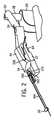
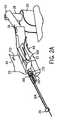
図2は、ロボット血管カテーテルシステム10の好ましい実施形態を示している。連結アーム18は、アームサポート20に連結しているとともにアームサポート20から外方向に突き出ている。モータ駆動ベース部22は、連結アーム18に連結している。カセット24は、モータ駆動ベース部22の頂上部に連結している。 FIG. 2 shows a preferred embodiment of the robotic
連結アーム18は、患者30に対して無限位置に固定されるように構成されている。好ましい実施形態において、連結アーム18は第1の関節32と第2の関節34とを備える。第1の関節32は、連結アーム18を垂直軸および/または水平軸を中心に回転することができる。第2の関節34は、連結アーム18を上下に回転させるまたは水平軸を中心に回転させることができる。連結アーム18は、患者に対して適切に位置決めするためにカセット24をいかなる方向にも位置決めすることができるように、複数の自由度を有してもよい。ユーザが連結アーム18を調整した後、連結アーム18は、連結アーム固定機構により所定の位置に固定され、処置の間の不要な動作を防止される。連結アーム固定機構は、ソレノイドを使用する他、連結アーム18を患者30に対してモータ駆動ベース部22およびカセット24に沿って固定可能な機構を使用して機械的に固定・固定解除されてもよい。 The connecting
図3には、カセット24をモータ駆動ベース部22に取り付ける前の図2に示すベッドサイドシステム12が示されている。モータ駆動ベース部22は、筐体38と複数のキャプスタン40を備える。キャプスタン40は、垂直方向に延在し、モータ駆動ベース部22およびカセット24を連結する際にカセット24を直線状に並べ易くする。カセット24は、筐体42と、筐体42に回転可能に取り付けられたカバー44と、モータ駆動ベース部22およびカセット24を連結する際にカセット24を直線状に並べ易くするためのモータ駆動ベース部22上に形成されたキャプスタン40に対応する複数のキャプスタンソケット46とを備える。1つの実施の形態において、キャプスタン40はおおよそ上方向に延在し、カセット24の底面に位置するキャプスタンソケット46内に挿入し受けられる。これにより、カセット24は、モータ駆動ベース部22の上でおおよそ下向きに設置される。モータ駆動ベース部22とカセット24とは、動作位置において水平面に対して角度を有し、ガイドカテーテルおよびガイドワイヤ、作動カテーテルを患者対して斜め下方向に方向付けすることを意図している。キャプスタン40およびキャプスタンソケット46は、モータカプラーの1つの実施の形態であり、モータをカセット内の軸および回転駆動機構に連結する。キャプスタン40およびキャプスタンソケット46がギヤを備えるようにして、回転力をモータ駆動ベース22内のモータからカセット内の軸および回転駆動機構に伝達するようにしてもよい。キャプスタンおよびキャプスタンソケットによって、カセットは下側に位置するモータ駆動ベース部上に設置できるが、モータを駆動機構に連結することが可能な他のモータカプラーによって設置できるようにしてもよい。1つの実施の形態において、モータはモータ駆動ベース部22内に位置する。しかし、モータ駆動ベース部22を使用して、モータ駆動ベース部から離れた位置でモータ駆動ベース部に動作可能に連結するモータからの力を、ケーブルや他の機械的連結部などの機械的リンケージによって伝達してもよい。また、機械的連結部によってモータをキャプスタンソケットに直接接続し、モータ駆動ベース部22によってカセット24を支持し、カセットキャプスタンソケットをモータに対して連結することも検討されうる。 FIG. 3 shows the
図2に示すように、カセット24内部のガイドワイヤやカテーテル器材の装着や取り外しを容易にするために、カバー44を開くことでカセット24内部の機械にアクセスできるようにしてもよい。カバー44は、以下に詳しく記載するように伝達機構内にガイドワイヤを確実に設置できるように壁部材を備えてもよい。カバー44は、ヒンジやその他の回転を可能にする部材で固定されてもよい。また、カバー44は、上下配置で固定してもよい。カバー44の開閉動作によって、伝達機構からガイドワイヤやその他のカテーテル器材が取り外されるようにしてもよい。 As shown in FIG. 2, in order to easily attach and remove the guide wire and catheter equipment inside the
カセット24をモータ駆動ベース部22に連結する前に、減菌したプラスチックカバー(図示せず)で連結アーム18とモータ駆動ベース部22を覆う。この滅菌したプラスチックカバーは、モータ駆動ベース部22上のキャプスタン40に対応する事前に開けられた穴を有する。この滅菌したプラスチックカバーは、ロボット血管カテーテルシステム10の滅菌済の構成要素をモータ駆動ベース部22や連結アーム18、アームサポート20などの未滅菌の構成要素から遮断する。カセット24は、使用前に滅菌する。カセット24がモータ駆動ベース部22に連結して使用されると、そのカセットは廃棄され、別の滅菌済の1回利用のカセットと交換される。 Before connecting the
図6から9において、カセット24は、ガイドワイヤ50をその長手方向軸に沿って駆動するための第1の軸駆動機構48と、作動カテーテル54をその長手方向軸に沿って駆動するための第2の軸駆動機構52と、ガイドワイヤ50をその長手方向軸に沿って独立して移動可能でかつガイドワイヤを回転する第1の回転駆動機構56とを更に備える。作動カテーテル54は、バルーンまたは送達カテーテル上のステント、バルーンを備えるステント、その他の治療または診断用カテーテル装置として実現してもよい;これらの実施の形態を集合的に作動カテーテル54とする。1つの実施の形態において、第1の軸駆動機構48および第1の回転駆動機構56は実質的にカセット24の長手方向軸60に沿って直列に配置する。1つの実施の形態において、第2の軸駆動機構52は、第1の軸駆動機構48に対して角度をつけて配置する。 6-9, the
ガイドワイヤ50および作動カテーテル24のカセット24内に設けられた駆動機構への装填は、カセット24とモータ駆動ベース部22とを連結した後でかつ処置のためにロボット血管カテーテルシステム10を使用する前でなければならない。カセット24を装填する際に、ユーザはカバー44を開ける。カバー44を開ける際には、係合−離脱機構が作動し、駆動機構を自動的にクイックアクセスするための調整がなされる。カセット24のカバーが開位置にある時には、駆動機構は、ガイドワイヤ50および作動カテーテル54を装填するための場所に位置している。カバー44を閉じる際には、係合−離脱機構が作動し、駆動機構を自動的に調整し、ガイドワイヤ50および作動カテーテル54を開放可能に係合する。また、カバー44が開位置にある時に、ガイドワイヤ50を係合および/または離脱するようにしてもよい。カセット24がカバー閉位置にある時、駆動機構は、ガイドワイヤ50および作動カテーテル54を駆動するのに十分な圧力を与える。好適な実施形態において、カバー4は、明るく半透明な材料からなり、カバーがカバー閉位置であっても駆動機構を見ることができる。また、当業者であれば、他の種々の材料も好適であることが分かる。カバーを開けても、開けなくても、機械的スイッチまたは電気機械的装置により駆動機構を離脱することができる。駆動機構が離脱することで、軸駆動機構のピンチローラ表面と回転駆動機構の係合面とがそれぞれ離間し、ガイドワイヤと作動カテーテルが容易に取り外しまたは挿入することができる。少なくとも1つのピンチローラは、ピンチローラ表面をそれぞれ物理的に離間する少なくとも1つの離脱機構によって支持されている。同様に、回転駆動機構の係合表面は、離脱機構と作動可能に接続しており、回転駆動機構の係合表面がお互いに物理的に離間する。ピンチローラ表面がそれぞれ離間位置にあるとき、ピンチローラは離脱状態にある。 Loading of the
カセット24はまた、装着時にカセットをセルフテストするシステム(図示せず)を備えてもよい。カセット装着のセルフテストをするシステムは、ワークステーション14において作業者によって作動させてもよい。また、カバー44を閉じた際にカセットのセルフテストを自動的にこのシステムが開始するようにして、それぞれの駆動機構をテストしてもよい。モータからワークステーション14に対するフィードバックによって、ベース部にカセットが適切に装着されていることを確認することができる。各モータがカセットに適切に装着されていることをテストすることに加え、各伝達機構を作動させ、ガイドワイヤおよび/または作動カテーテルを所定の距離または所定の回転量だけ動かし、実際の移動距離または回転量をセンサによって計測するようにしてもよい。移動量が所定のパラメータと一致する場合は、作動中および動作可能な状態にあることをシステムは示す。ガイドワイヤおよび/または作動カテーテルの検出移動量が、所定のパラメータと一致しなかったら、システムはエラーメッセージを示す。
カセットは、人間工学を考慮して設計されており、作業者は、ハンドル64によってカセットおよびカセットベース部を容易に操作、移動させ、患者に対して本システムを位置させることができる。カバー44は、カバー表面内側またはカセット筐体部に設けられるとともに交換中または2つ以上のワイヤを操作する際にガイドワイヤ50を保持するラッチ210を備えてもよい。カテーテルシステム10は、作動カテーテル54を膨張させるシステムと、造影剤を注入するシステムとを備えていてもよい。つまり、ワークステーション14は、造影剤を注入するポンプを遠隔制御する制御機構を備えていてもよい。 The cassette is designed with ergonomics in mind, and the operator can easily manipulate and move the cassette and cassette base by the
図9には、カバー44および筐体42が無い状態のカセット24が示されている。カセット24は、第1の軸駆動機構48および第1の回転駆動機構56を支持するベースプレート部70を備えている。軸駆動機構48および回転駆動機構56は、ベースプレート部70の長手方向軸に沿って連続的にまたは順次に配列および固定されている。第1の軸駆動機構48は、カセット24の後端側で第1の回転駆動機構56の後ろに近い場所に配置されているように示されている。なお、第1の回転駆動機構56は、第1の軸駆動機構48の後ろに配置してもよい。回転駆動機構56を患者に近い位置に配置することで、軸駆動機構48内のローラからの圧力および/または摩擦が、患者から離れたところに位置するようになるため、ガイドワイヤの回転制御を向上することができると考えられている。 FIG. 9 shows the
図9および図10において、第1の軸駆動機構48は、軸方向にガイドワイヤ50を駆動するために、それぞれ協働する第1のローラ72と第2のローラ74とを備える。第1のローラ72は、第2のローラ74方向にスプリング付勢されており、ローラ72、74が回転する際にガイドワイヤ50を十分に移動させることができる力が付与されている。スプリング力を調整して、システムを確実にかつ適切に作動することができるようにしてもよい。スプリング力は、ガイドワイヤ50をその軸を中心として回転できるように設定されている。一実施形態において、第1のローラ72は第1の係合表面を備えており、第2のローラ74は第2の係合表面を備えている。ガイドワイヤ50は、第1のローラ72の第1の係合表面と、第2のローラ74の第2の係合表面との間に取り外し可能に設置されている。ソレノイドを使用して、第1のローラと第2のローラをそれぞれ近接、離間させ、第1のローラ72と第2のローラ74との間でガイドワイヤを捕捉、開放するようにしてもよい。ソレノイドを使用して、1つのローラを他のローラに向けて支持するホルダーを移動させるようにしてもよい。ホルダーのスプリングを使用して、1つのローラを他のローラに付勢し、少なくとも1つのローラを回転させる際に、ガイドワイヤをその長手方向軸に沿って効果的に移動できるだけの十分な力をガイドワイヤ50に与えるようにしてもよい。 9 and 10, the first
第2のローラ74は、ベルト78を介して駆動ギヤまたはローラ76によって駆動する。ベルト78には、テンション部材80を介して十分な張力を付与する。しかし、第2のローラは、モータ駆動ベース部22内のキャプスタン40の1つから直接駆動してもよい。 The
別の実施形態では、ローラ72、74対には、ローラとアンビル、またはローラと任意のグリップ表面を備えており、このグリップ表面とローラとの間の圧力は、ガイドワイヤ50をその長手方向軸に沿って駆動するのに充分なものである。 In another embodiment, the pair of
図6および9、11において、第1の回転駆動機構56は、第1の回転駆動機構支持ブロック92と、第2の回転駆動機構支持ブロック94と、回転駆動機構96とを備えている。回転駆動機構96は、プレート部100と、4対のローラ102、104、106、108と、4対のローラ回転軸118、120、122、124上で支持された4対のローラ留め具110、112、114、116と、回転駆動機構コームと、長手方向軸128と、各支持ブロック92、94内の孔を貫通し、その孔に支持されている1対の円筒状突起部130とを備えている。1対の円筒状突起部130、132は、回転駆動機構96と実質的に同心円上にあり、回転駆動機構96の長手方向軸128に沿って回転駆動機構96のどちらかの端から外方向に延在している。第1の回転駆動機構支持ブロック92および第2の回転駆動機構支持ブロック94は、ベースプレート部70の長手方向軸128に対して横断しており、それぞれのブロック間に回転駆動機構96を十分に収容できる距離だけ、ベースプレート部70の長手方向軸に沿って離間している。回転駆動機構96は、ベースプレート部70をまたいで第1の回転駆動機構支持ブロック92および第2の回転駆動機構支持ブロック94間に、1対の円筒状突起部130、132によってつり下げられ、固定されている。この円筒状突起部130、132はまた、ガイドワイヤ50が延在する通路の役割を果たす。図14において、回転駆動機構96のそれぞれの要素は、支持ブロック92、94間において回転する回転アッセンブリ206上で支持されている。 6, 9, and 11, the first
各支持ブロック92、94は、回転駆動機構96の長手方向軸128から半径方向外側に実質的に延在するガイドワイヤスリット84を備えている。4対のローラ102、104、106、108は、それぞれ回転駆動機構96の長手方向軸に沿って接触している。4対のローラ102、104、106、108および4対のローラ留め具110、112、114、116は、4対の回転軸118、120、122、124にまたがって位置しており、4対のローラ留め具110、112、114、116が4対の回転軸118、120、122、124に沿って、4対のローラ102、104、106、108を固定している。回転駆動機構は、4対のローラを備えるように説明したが、1対または2対、3対のローラを使用してもよいし、5対以上のローラを使用してもよい。図14において、要素208は、回転アッセンブリが装着位置および非装着位置にあるときに、ガイドワイヤ50が貫通する通路を示している。回転アッセンブリが装着位置および非装着位置にあるとき、要素208で示される通路は、図9に示す支持ブロック92、94内においてガイドワイヤスリット84と一列に配置されている。 Each
カセット24のカバー44が閉位置にあるとき、回転駆動機構ロケータを、回転駆動機構96の長手方向軸に向かって下方にガイドワイヤ50を位置決めする際の補助として使用し、ガイドワイヤ50を4対のローラ102、104、106、108の間に配置、保持しやすいようにしてもよい。ガイドワイヤ50を、第1の回転駆動機構56内で4対のローラ102、104、106、108間に開放可能に係合させる。ロボット血管カテーテルシステム10が処置中に使用されるとき、4対のローラ102、104、106、108の係合表面内の各ローラは、お互いの方向に移動し、ガイドワイヤ50の長手方向軸に沿って軸駆動機構48によりガイドワイヤ50を独立して移動可能な状態に維持しつつ、回転駆動機構96が回転する際にガイドワイヤ50を回転させるのに十分な圧力を加える。ガイドワイヤ50は、回転駆動機構96が回転する際の4対のローラ102、104、106、108間の摩擦力によりガイドワイヤ50に与えられたトルクによって、回転する。ローラ対102〜108内の各ローラは、その垂直軸を中心に回転自由に設けられており、ガイドワイヤ50を軸移動可能にしている。各ローラ対間の圧力は、回転駆動機構全体が回転するときに、その間に位置するガイドワイヤ50に対して回転を与えるのに十分な圧力となっている。回転駆動機構内にガイドワイヤを装填、取り外しする際に、ガイドワイヤ50を容易に挿入、取り外しできるように、ローラをお互いに離間するようにしてもよい。カバー44が開位置にあるときに、1つのローラ対を、他のローラ対から離間させるようにして、カバー44が閉位置にあるときに、他のローラ対に向かって再度移動するようにしてもよい。ローラ間において、回転駆動機構に対してガイドワイヤ50を容易に挿入、取り外しできるように、垂直パス98を、ガイドワイヤスリット84に対して1直線状に並べなければならない。カバー44を開いたときは、垂直パス98がガイドワイヤスリット84と直線状に並べられ、ガイドワイヤ50を回転駆動機構に対して容易に挿入および/または取外しできる装填/取外位置まで、回転駆動機構を回転する。別の実施形態では、ローラをお互いに離間させずに、ローラ間に対してガイドワイヤ50を手動で挿入、取外しできるようにしてもよい。ローラ自身に可撓性を設けて手動で挿入するようにしてもよいし、スプリング付勢されたローラのうちの1つを、ローラ対中の別のローラから離間させて、ガイドワイヤ50を挿入できるようにしてもよい。 When the
4対のローラ102、104、106、108に関する別の実施形態として、4対以上のローラがある。4対のローラ102、104、106、108は、ローラとアンビルとの対となっている。各ローラがアンビルと一対となり、ガイドワイヤ50の長手方向軸に沿ってガイドワイヤ50を独立して移動可能な状態に維持しつつ、回転駆動機構96が回転する際にガイドワイヤ50を回転させるのに十分な圧力を加える。同様に、4対のローラ102、104、106、108を、複数のローラと任意のグリップ表面とから構成し、ガイドワイヤ50の長手方向軸に沿ってガイドワイヤ50を独立して移動可能な状態に維持しつつ、回転駆動機構96が回転する際にガイドワイヤ50を回転させるのに十分な圧力を加えるようにしてもよい。別の実施形態において、回転駆動機構は、2つの係合表面を備えてもよく、この2つの係合表面は、ガイドワイヤの長手方向軸の軸方向に、回転してもよいし、回転しないでもよい。 Another embodiment for the four pairs of
カセット24のカバー44が開カバー位置にあるとき、第1の軸駆動機構48および第1の回転駆動機構56が、ガイドワイヤ50および作動カテーテル54を装填しやすいように配置してもよい。挿入、回転位置において、支持ブロック92、94内のガイドワイヤスリット84および回転駆動機構96のガイドワイヤパス98を実質的に直線上に配置する。同様に、第1の軸駆動機構48のローラ対72、74および第1の回転駆動機構56の4対のローラ102、104、106、108を実質的に直線上に配置する。これにより、ガイドワイヤ50を、第1の軸駆動機構48および第1の回転駆動機構56を貫通させて、延在させることができる。上記したように、軸駆動機構および回転駆動機構内の各ローラ対を離間させて、カバー44が開位置にあるときに、ガイドワイヤ50を容易に挿入、取り外しするようにしてもよい。 When the
図6において、第2の軸駆動機構52は、ローラ対136と作動カテーテルチャンネル138とを備えている。ローラ対136は、作動カテーテルチャンネル138内において、作動カテーテル54と開放可能に係合している。カセット24が開位置にあるとき、第2の軸駆動機構52は、ローラ対136間の作動カテーテル54を装填しやすいように、配置する。カセット24のカバー44が閉じているとき、作動カテーテル54を装填し、ローラ対136間に開放可能に係合させる。第2の軸駆動機構52の別の実施形態としては、ローラ対136が、ローラとアンビル、またはローラと任意のグリップ表面とからなり、グリップ表面とローラとの間の圧力が、作動カテーテル54をその長手方向軸に沿って駆動するのに十分な圧力である実施形態が挙げられる。その他の軸駆動機構を検討し、使用してもよい。 In FIG. 6, the second
図1において、ワークステーション14は、ユーザインターフェース142を備える。ユーザインターフェース142により、ユーザは、第1の軸駆動機構48を経由してガイドワイヤ50を軸方向運動するように制御するコマンドと、第2の軸駆動機構52を経由して作動カテーテル54を軸方向運動するように制御するコマンドと、第1の回転駆動機構56を経由してガイドワイヤ50を回転運動するように制御するコマンドとを入力することができる。ロボット血管カテーテルシステム10の別の実施形態においては、ユーザは、ワークステーション14からガイドカテーテル144を軸制御および/または回転制御することもできる。 In FIG. 1, the
好適な実施形態において、ユーザインターフェース142は、第1のスクリーン146および第2のスクリーン148を備える。第1のスクリーン146および第2のスクリーン148は、ロボット血管カテーテルシステム10に関してユーザにとって有益であると思われる情報および画像を提示するように構成されている。ユーザインターフェース142は更に、様々な速度制御を有する一対のジョイスティック152を有するタッチスクリーン150と、1mm用第1のジョグボタン154と、5mmジョグ用第2のジョグボタンとを備える。第1のジョグボタン154および第2のジョグボタン156は、連続ジョグ機能を有する。ジョグボタンを押下することで、所定の距離だけガイドワイヤ50が前進する。ジョグボタンを、ガイドワイヤ50および/または作動カテーテル54を移動するために使用してもよい。回転ジョグボタンは、所定角度だけ回転するように設定してもよく、選択した角度だけ回転するように設定してもよい。別のボタンを、ガイドワイヤ50の速度を加速させるために、または可変速度制御が増加反応するように倍率器として機能させるために、使用してもよい。例えば、通常動作において、ジョイスティックを所定の距離だけ動作させると、ガイドワイヤは設定速度で動作するが、加速するボタンを押下することで、設定速度を倍増させてガイドワイヤを動作する。 In the preferred embodiment, the
別の実施形態において、ユーザインターフェース142は様々な構成としてもよい。例えば、タッチスクリーン150は、X線や他の撮像データと統合してもよい。実際に、造影剤注入制御やバルーン膨張制御、画像処理制御、血行力学データ等のような種々なデータや制御を単一スクリーン上で統合してもよい。別のジョイスティックの構成としては、全ての駆動機構を制御する2つのジョイスティックではなく、駆動機構毎に個別のジョイスティックを設けるようにしてもよい。 In other embodiments, the
ロボット血管カテーテルシステム10は更に、数多くの安全上の特徴および機能(図示せず)を備えていてもよい。例えば、ロボット血管カテーテルシステム10は、処置中にユーザが手動で動作することができるような機構を備えていてもよい。作業者が、回転駆動機構を手動で位置決めしてガイドワイヤ50を取り外す場合、回転駆動機構を装填/取り外す位置まで移動して、回転駆動機構の係合表面を分離し、回転駆動機構支持部内のスリットに合わせるようにすることが考えられる。また、ワークステーション14には、ユーザが音声作動制御をして、緊急停止動作に切り替える機能を有するシステムを備えていてもよい。ロボット血管カテーテルシステム10は、ガイドワイヤ50上に設置する際の力を所定の値以下に抑えることもできる。この所定値を超える力をモータが印加しようとしたら、車輪をモータから離脱するようにクラッチを作動させる。例えば、任意の駆動機構が動かなくなり、回転不能となったら、動かなくなった駆動機構やモータ自身を損傷せずにモータが回転できるようにクラッチ機構が作動する。 The robotic
別の可能な特徴としては、滑り検出機構がある。このような機構によって、ガイドワイヤ50または作動カテーテル54およびローラや、第1の軸駆動機構48のローラ対72、74、第1の回転駆動機構56の4対のローラ102、104、106、108の所望の動作と実際の動作とを連続的に確認することができる。この機構により、所定の閾値を超えた場合、警告を発することができる。この閾値は、処理期間中一定としてもよいし、心臓内部におけるシステム部品の場所によって変えてもよい。一実施形態において、補助エコーダ(図示せず)を使用して、処理中の軸動作および回転動作に関するガイドワイヤ50の正確な位置および軸動作に関する作動カテーテル54の正確な位置を得るようにしてもよい。ローラ対72、74および4対のローラ102、104、106、108を、複数のアイドラーローラ158近傍に配置してもよい。このアイドラーローラ158は、ロボット血管カテーテルシステム10の動作を確認し、ローラの移動とモータの動作とを比較する。なお、これらの特徴および機能は、代表例を示したものであり、全てものを表していると解釈されない。 Another possible feature is a slip detection mechanism. By such a mechanism, the
図3、7、8、13の好適な実施形態において、カセット24は更に、ロッド164として示すガイドカテーテル支持アームとガイドカテーテル144とに取り付けられたYコネクタ160を固定する連結機構162を備える。連結機構162は、開放可能にYコネクタ160に固定されている。Yコネクタ160は、ガイドカテーテル144に接続している。Yコネクタ160は更に、PCI処置中に患者に薬剤を投与するための手段として機能する。一実施形態において、ロボット血管カテーテルシステム10によって、ユーザは、Yコネクタ160を介した薬剤投与の遠隔操作を実施することができる。ガイドカテーテル144は、その長手方向軸を中心に、Yコネクタ160とは独立して回転することができるようにしてもよい。第1の脚部は、ガイドカテーテル144に取り付けられている。第2の脚部は、ガイドカテーテルの長手方向軸から離れるように角度が付けられており、造影剤や薬剤を投与することができる。一方向バルブが、体液が第2の脚部から流出することを防いでいる。第3の脚部は、ガイドカテーテルから離れるように延在しており、Yコネクタにより作動カテーテルおよびガイドワイヤを挿入可能にしている。第3の脚部は、作動カテーテルおよびガイドワイヤの挿入、取り外しを可能にし、体液が第3の脚部から流出することを防ぐ一方向バルブを備えている。 In the preferred embodiment of FIGS. 3, 7, 8, and 13, the
ロッド164は、カセット24の前端に沿った位置でカセット24に連結しており、その他端でガイドカテーテルサポート26を支持している。ロッド164は、調整可能であり、カセット24に対して近接離間することができ、またカセット24とは独立して移動することができ、既知の方法を利用してガイドカテーテル24の位置決めを容易にする。別の実施形態において、ロッド164は、ガイドカテーテルサポート26およびガイドカテーテル144を支持可能な任意数の構成を備えていてもよい。例えば、ガイドロッド164は、テレスコーピング部を備えていてもよい。 The
スプリング装填クランプとして示すガイドカテーテルサポート26によって、ガイドカテーテル144は支持される。処置中、ガイドカテーテルサポート26は、カセット24の前端と患者30との間に配置される。この位置において、ガイドカテーテルサポート26は、ガイドカテーテル144とその内容物の好ましくない動きを抑え、高精度な処置を実施可能にする。
図6において、ガイドワイヤ50および作動カテーテル54がロボット血管カテーテルシステム10内に装填されると、カセット24のカバー44は閉じられ、ガイドワイヤ50は、筐体42内の開口部を通ってカセット24の後端から延伸することとなる。ガイドワイヤ50は、カセット24の前端に向けて移動し、第1の軸駆動機構48および第1の回転駆動機構56を通り、集合領域166で作動カテーテル54と集合する。作動カテーテル54は、筐体42の側面内のスロット168を通って、カセット24に入る。集合領域166でガイドワイヤ50と集合する前に、作動カテーテル54は、まず第2の軸駆動機構52を通過する。作動カテーテル54は、ワイヤ部分に対して空洞となっており、集合領域166でガイドワイヤ50は挿入する。そのワイヤ部分内のガイドワイヤ50を伴った作動カテーテル54は、開口部172を通ってカセット24の前端から出る。カセット24は、作動カテーテルの長手方向軸とガイドワイヤの長手方向軸とが同軸にない第1の点から、作動カテーテルの長手方向軸とガイドワイヤの長手方向軸とが同軸にある第2の点に向かう所定の通路に沿って、作動カテーテルを導くチャンネルを備えていてもよい。この通路は、筐体内に設けられ、溝や少なくとも通路の一部を形成する他の物理的手段を備えていてもよい。 In FIG. 6, when the
さらに図6において、Yコネクタ160は、ガイドカテーテル144の近位端に接続している。ガイドカテーテル144は、中心孔を有する。ガイドワイヤ50および作動カテーテル54は、Yコネクタ160を通ってガイドカテーテル144の中心孔174に入り、開口部172を通ってカセット24から出る。好適な実施形態において、ガイドカテーテル144は、Yコネクタ160から、ガイドカテーテルが開放可能に固定されているガイドカテーテルサポート26に向かうロッド164に対して実質的に平行に延在する。ガイドカテーテルサポート26は、ガイドカテーテル144を直線状に維持するように機能し、ガイドカテーテル144の中心孔174において、ガイドワイヤ50および作動カテーテル54の移動を容易にする。 Further in FIG. 6, the
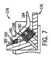
Yコネクタ160は、図7および8の実施形態においてはスプリング付勢クランプとして示す連結機構162によって、カセット24と開放可能に固定されている。クランプ機構162は、フレーム176と、ハンドル178と、少なくとも1つのスプリング180とを備える。フレーム176は、Yコネクタ160が固定される受け部182を備えている。ハンドル178は、レバーアーム184および捕捉部186を備える。捕捉部186は、レバーアーム184が押下されていないときに、フレーム176の受け部182に対してYコネクタ160を固定するのに十分な圧力を加える。ハンドル178は、回転部188を中心に回転する。スプリング180は、回転部188から離れた場所でレバーアーム184に対して上方向の力を加え、ハンドル178の捕捉部186をフレーム176の受け部182に対して付勢する。図8において、レバーアーム184が押下されたとき、スプリング180もまた圧縮される。ハンドル178の捕捉部186は、回転部188を中心に回転し、Yコネクタ160および受け部182から離間し、Yコネクタ160を開放する。図7において、ハンドル178が開放されるとき、レバーアーム184に対して上方向に力が加えられ、レバーアーム184は回転部188を中心に回転する。捕捉部186は、受け部182およびYコネクタ160に向けて移動し、Yコネクタ160を開放可能に固定する。 The
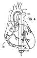
実施例の処置は、(図4に示す)心臓190内部に診断用ガイドワイヤ(図示せず)を残した状態において、診断処置完了後に開始される。心臓190には、大動脈192および大動脈弓194が備えられている。ロボット血管カテーテルシステム10を使用する前に、ガイドカテーテル144を、診断用ガイドワイヤ上を大動脈192まで移動し、診断用ガイドワイヤを取り除き、ガイドカテーテル144を、病巣の位置に応じて、右冠状動脈に対して開口する右側開口部196または弓状もしくは左前下降枝に対して開口する左側開口部198のどちらかの内部に配置する。ガイドカテーテル144の形状は、挿入する孔に応じて変化する。上記したように、ベッドサイドシステム12は、多くの場合、患者のベッド28に対して既に固定されている。 The procedure of the example is started after the completion of the diagnostic procedure, with a diagnostic guide wire (not shown) left inside the heart 190 (shown in FIG. 4). The
明確にするために、ガイドカテーテル50および作動カテーテル54を前進させる工程と、ベッドサイドシステム12を装着する工程をそれぞれ順番に説明する。当業者であれば、工程の説明は、本方法から大きく逸脱しない範囲内において、交換可能であることを認識する。 For clarity, the steps of advancing the
ガイドカテーテル144は、Yコネクタ160に取り付けられている。Yコネクタ挿入装置(図示せず)をYコネクタ160内に配置する。ガイドワイヤ50を、Yコネクタ挿入装置を介してガイドカテーテル144内に前進させ、その後取り外す。作動カテーテル54は、ガイドワイヤ50に装着する。作動カテーテル54を、ガイドワイヤ50の自由端付近に到達するまで、ガイドワイヤ50上をガイドカテーテル144内で前進させる。 The
カセット24を、滅菌したプラスチックカバー上でモータ駆動ベース部22に連結する。連結アーム18を患者30に対して固定し、カセット24のカバー44を開き、係合−離脱機構を作動させ、ガイドワイヤ50および作動カテーテル54を装着するために駆動機構を位置決めする。ガイドワイヤ50を、第1回転駆動機構56の4対のローラ102、104、106、108間のガイドワイヤパス98内に配置し、ガイドワイヤスリット84および第一の軸駆動機構48のローラ対72、74内に配置する。ガイドワイヤ50の後端は、開口部42の後部を通り外側に延伸しており、ガイドワイヤ保持部や支持部を備え、患者内で使用しないガイドワイヤ部分を収納する。作動カテーテル54を、第2の軸駆動機構52のローラ対136間の作動カテーテルチャンネル138内に設置する。ガイドワイヤ50および作動カテーテル54を位置決めした後、カセット24のカバー44を閉じ、係合−離脱機構を再度作動させる。ロボット血管カテーテルシステム10を装着し、各駆動機構をガイドワイヤ50および作動カテーテル54に開放可能に係合する。 The
ハンドル178を押下し、Yコネクタ160をフレーム176とハンドル178との間に配置し、カセット24に対してYコネクタ160を開放可能に固定する。 The
ユーザは、ワークステーション14で制御操作する。ワークステーション14の前記好適な実施形態において、タッチスクリーン150やジョイスティック対152、第1のジョグボタン154、第2のジョグボタン156を操作し、ガイドワイヤ50および作動カテーテル54の運動を方向付けする。図5に示すように、ガイドワイヤ50そしてその次に作動カテーテル54を、典型的には、ガイドワイヤ50が病巣200を横切るまで移動させる。ガイドワイヤ50が病巣200を横切ったら、第1のジョグボタン154、第2のジョグボタン156あるいはその組み合わせにより位置を微調整することで作動カテーテル54も横切るように駆動する。 The user performs a control operation on the
図12において、別の軸駆動212部材を使用してもよい。例えば、ピンチローラを、2つのベルト機構と置き換えてもよい。 In FIG. 12, another
図13において、カセット24は、ガイドカテーテルサポート202を備えてもよい。Yコネクタ連結機構は、ガイドカテーテルサポート202に支持されている。別の実施形態において、ガイドカテーテルがその長手方向軸に沿う方向に移動するように、ガイドカテーテルサポート202は、前後方向に移動可能なスレッド204を備えてもよい。カセット24はまた、ガイドカテーテルをその長手方向軸を中心に回転するように、スレッド204を回転させる駆動機構と、ガイドカテーテルをガイドワイヤの長手方向軸に沿って移動するように、スレッド204を前後方向に移動させる駆動機構とを備えてもよい。スレッド204を移動させる前記駆動機構は、モータ駆動ベース部22内に配置し、スレッド204をカセット24に対して移動させてもよく、これによりスレッド204は、ガイドワイヤおよび/または作動カテーテルと独立して移動することができる。 In FIG. 13, the
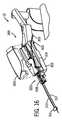
図15から28Cでは、ロボットカテーテルシステムに使用するカセットの別の実施形態を示す。前述の実施形態と同様に、カセット300は、ガイドワイヤ301および作動カテーテル303を備えてもよく、これによりユーザはカセット300を使用して、カテーテル処置を実施することができる。この実施形態において、ベッドサイドシステム12は、モータ駆動ベース部302に装着するように構成されたカセット300を備える。図15は、モータ駆動ベース部302に装着する前のカセット300を示す底部斜視図である。モータ駆動ベース部302は、第1のキャプスタン304と第2のキャプスタン306、第3のキャプスタン308を備えており、カセット300は、第1のキャプスタンソケット310、第2のキャプスタンソケット312、第3のキャプスタンソケット314を備える。カセット300は筐体部316を備えており、筐体部316はベースプレート部318を備えている。 Figures 15 to 28C show another embodiment of a cassette for use in a robotic catheter system. Similar to the previous embodiment, the
各キャプスタンソケットは、モータ駆動ベース部302のキャプスタンの1つを受けるように構成されている。実施形態において、ベースプレート部318は、各キャプスタンソケット310、312、314に対して位置決めされた孔または開口部を備えており、各キャプスタンとそれに対応するキャプスタンソケットとが係合可能である。キャプスタンとキャプスタンソケットとを係合することによって、モータ駆動ベース部302内に設けられた1つまたはそれ以上のアクチュエータ(例えばモータ)によって生成されたエネルギー(例えば回転動作)を、カセット300内の各駆動機構(以下に説明)に伝達することができる。一実施形態においては、単一のアクチュエータによって、各駆動機構にエネルギーが供給される。別の実施形態においては、キャプスタン304を駆動するアクチュエータと、キャプスタン306を駆動するアクチュエータと、キャプスタン308を駆動するアクチュエータとを備える。キャプスタンとキャプスタンソケットとを配置することにより、これら3つ全てのキャプスタンソケットが適切なキャプスタンに対して配列される場合にのみ、ユーザは、カセット300をベースプレート部302に対して容易に配置することができるようになる。 Each capstan socket is configured to receive one of the capstans of the motor
一実施形態において、キャプスタン304、306、308を駆動するモータは、モータ駆動ベース部302内に配置される。別の実施形態において、キャプスタン304、306、308を駆動するモータを、適切な伝達装置(例えばシャフトやケーブルなど)を介してカセット300に対して接続されているベース部302外に設けてもよい。更に別の実施形態において、カセット300は、カセット300の筐体内部に配置されたモータを備える。別の実施形態において、カセット300は、キャプスタン304、306、308を備えずに、カセット外部に設けられたアクチュエータからのエネルギー(例えば回転運動)を、各カセット駆動機構に伝達する別の機構を備えてもよい。例えば、回転動作を、交互もしくは回転磁石またはモータ駆動ベース部302内に設けられた磁界を介してカセット300の駆動機構に伝達してもよい。 In one embodiment, the motor that drives the
実施形態において、カセットはまた、カセット300から離れた位置においてガイドカテーテル317を支持するガイドカテーテルサポート311を備える。図示するように、ガイドカテーテルサポート311は、ロッド313によりカセット300に取り付けられている。ロッド313およびガイドカテーテルサポート311は、座屈せずにガイドカテーテル317を支持できるだけの強度を備えている。ガイドカテーテルサポート311は、患者とカセットとの間のカセットから離れた位置でガイドカテーテル317を支持し、カセットと患者との間においてガイドカテーテル317部が座屈や屈曲することを防止する。 In an embodiment, the cassette also includes a
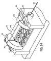
図16において、カセット300は、モータ駆動ベース部302に対して装着するように示されている。図16に示すように、カセット300は、筐体316に取り付けることができる外部カセットカバー320を備えている。筐体316に取り付ける際には、外部カセットカバー320を、カセット300の各駆動機構上に配置し、これら各駆動機構を覆うようにする。カセット300の各駆動アッセンブリを覆うことで、外部カセットカバー320は、使用中にカセット300の各駆動機構に偶発的に接触することを防ぐ役割を果たす。 In FIG. 16, the
図17においては、外部カセットカバー320が取り外された、「装填中」位置のカセット300の構成を示している。カセット300は、Yコネクタサポートアッセンブリ322と、軸駆動アッセンブリ324と、回転駆動アッセンブリ326とを備えている。一般に、カセット300の多くの部分が、上記装填中の構成に含まれており、ユーザが、カセット300中にガイドワイヤおよび/または作動カテーテルを装填または設置することができる。また、図示した実施形態例において、Yコネクタサポートアッセンブリ322は、軸駆動アッセンブリ324の前に設けられており、軸駆動アッセンブリ324は、カセット300内の回転駆動アッセンブリ326の前に設けられている。 FIG. 17 shows the configuration of the
Yコネクタサポートアッセンブリ322は、シャーシ328およびYコネクタ拘束部330を備える。ベースプレート部318は、Yコネクタサポートアッセンブリ322を支持するサポートアーム332を備える。シャーシ328は、ピン接続部334を介してサポートアーム332の全部と連結している。 The Y
中央溝または凹部336は、シャーシ328の長さにわたって延在している。Yコネクタ338が、シャーシ328の中央溝336内に配置されている。Yコネクタ338は、第1の脚340と、第2の脚342と、第3の脚344とを備える。第1の脚340は、Yコネクタの中央管腔が、ガイドカテーテルの第2の脚342は、Yコネクタ338の長手方向軸に対して離間するよう傾けられている。Yコネクタ338の第2の脚342によって、造影剤や薬剤をガイドカテーテルの管腔内に投与することができる。一方向バルブによって、第2の脚342から体液が流れ出ることを防ぐ。第3の脚344は、軸駆動アッセンブリ324に向かって、ガイドカテーテルから延在している。使用中は、ガイドワイヤ301および作動カテーテル303を、開口部346を介してYコネクタ338の第3の脚部344に挿入し、ガイドカテーテルの管腔内にYコネクタ338を介して前進させるようにしてもよい。第3の脚はまた、作動カテーテルおよびガイドワイヤを挿入、取り外しすることができるが、第3の脚344から体液が流れることを防ぐ一方向バルブを備えている。中央管腔と流体連通するようにガイドカテーテルに取り付けられて構成されている。 A central groove or
シャーシ328は、ピン接続部334によって規定される軸を中心に回転可能であり、シャーシ328を図17に示す「装填中」位置に配置することができる。装填中位置において、シャーシ328は、サポートアーム332に対して傾斜線315で示される約45°の角度で配置される。シャーシ328は、「装填中」位置に移動することで、第3の脚344の開口部346に対して容易にアクセスできるようになり、ユーザはガイドワイヤ301および作動カテーテル303をYコネクタ338内に挿入することができる。 The
Yコネクタサポートアッセンブリ322は、Yコネクタ拘束部330を備える。Yコネクタ拘束部330は、Yコネクタ338に開放可能に係合するよう構成されている。図17に示す係合済位置において、Yコネクタ拘束部330の係合アーム348は、Yコネクタ338に係合もしくは中央溝336内にYコネクタ338を押圧し、Yコネクタ338を確実に保持する。Yコネクタ拘束部330は、離脱位置に移動し、Yコネクタ338をシャーシ328から開放するようにしてもよい。 The Y
カセット300はまた、軸駆動アッセンブリ324を備える。軸駆動アッセンブリ324は、ガイドワイヤ軸駆動機構350として示される第1の軸駆動機構と、作動カテーテル軸駆動機構352として示される第2の軸駆動機構とを備える。軸駆動アッセンブリ324はまた、トップデッキ354と,カバー356と、ラッチまたはハンドル358とを備える。
一般に、ガイドワイヤ軸駆動機構350は、ガイドワイヤ301をその長手方向軸に沿って開放可能に係合および駆動(例えば、運動)するように構成されている。このようにして、ガイドワイヤ軸駆動機構350によって、ガイドワイヤ301を前進または後退させる。作動カテーテル軸駆動機構352は、作動カテーテル303をその長手方向軸に沿って開放可能に係合および駆動(例えば、運動)するように構成されている。このようにして、作動カテーテル軸駆動機構352によって、作動カテーテル303を前進または後退させる。 Generally, the guide wire
トップデッキ354は、ベースプレート部318の中央部360に装着されている。トップデッキ354は、ガイドワイヤチャンネル364および作動カテーテルチャンネル366を備える。ガイドワイヤチャンネル364は、トップデッキ354の頂上面に対しておおよそ垂直に配置され、トップデッキ354の長さが長手方向軸に延在するように構成する。作動カテーテルチャンネル366は、トップデッキ354の頂上面に対しておおよそ垂直に配置され、ガイドワイヤチャンネル364に対して角度を付けて配置される。複数のタブ368が、デッキ354の頂上面からガイドワイヤチャンネル364に沿って垂直に延在する。 The
図17において、カバー356は、開位置として示されている。ハンドル358は、カセット300の長手方向軸に対しておおよそ平行となる位置に移動し、カバー356が開位置に移動可能となる。カバー356は、ヒンジ370を介してトップデッキ354に装着されている。カセット300は、カバー356が閉位置にあるとき、ガイドワイヤの動きが拘束されるように機能する拘束構造を備えている。図示するように、拘束構造は、カバー356の下部表面から延在する複数のタブ372を備える。タブ372は、カバー356が閉位置にあるときに、タブ368間のガイドワイヤチャンネル364の位置内にタブ372が配置され、垂直方向において(すなわちトップデッキ354の頂上面に対して垂直方向のガイドワイヤ301の動き)ガイドワイヤ301の動きをタブ372が拘束するように、配置される。 In FIG. 17, the
カバー356が開位置にあるとき、ガイドワイヤ軸駆動機構350および作動カテーテル軸駆動機構352が露出し、ユーザがカセット330にガイドワイヤおよび作動カテーテルを装填できるようになる。カバー356が開位置にあるとき、ガイドワイヤチャンネル364内にガイドワイヤを設置することで、軸駆動アッセンブリ324内にガイドワイヤ301を装填する。タブ368によって、ユーザがガイドワイヤをガイドワイヤチャンネル364に対して位置決めしやすくなり、ガイドワイヤ301の設置が容易になる。また、作動カテーテル303は、作動カテーテルチャンネル366内に作動カテーテルを配置することで、軸駆動アッセンブリ324内に装填する。以下に詳しく説明するように、ガイドワイヤおよび作動カテーテルをそれぞれガイドワイヤチャンネル364内および作動カテーテルチャンネル366内に配置したら、ガイドワイヤ軸駆動機構350および作動カテーテル軸駆動機構352の係合面は、ガイドワイヤおよび作動カテーテルのそれぞれに係合する。 When the
ベースプレート部318のトップデッキ354および中央部360は、凹部374を区画形成する。作動カテーテルチャンネル366は、凹部374内に形成された開口部376を備える。凹部374によって、開口部376はYコネクタ338および入口切開部に近づき、Yコネクタ338や入口切開部からさらに離れる位置に開口部376が設けられている場合に比べて、作動カテーテル303が、患者の血管系内に更に前進可能になる。図16から分かるように、作動カテーテル303は、その近位端に、開口部376を貫通するには大きい寸法のハブ305を備える。よって、開口部376がYコネクタ338や入口切開部に近づけば、それだけ作動カテーテル303は、患者の血管系に前進することができる。 The
カセット300はまた、回転駆動アッセンブリ326を備える。回転駆動アッセンブリ326は、ガイドワイヤ回転駆動機構380として示される回転駆動機構と、カバー384と、ジャーナル388とを備える。ガイドワイヤ回転駆動機構380は、シャーシ382および係合構造体386を備える。回転駆動アッセンブリ326は、ガイドワイヤ301をその長手方向軸周りに回転させるように構成されている。ガイドワイヤ301と開放可能に係合するように構成されており、係合構造体386はまた、ガイドワイヤ軸駆動機構350によりガイドワイヤ301が軸移動可能な状態で、その長手方向軸周りにガイドワイヤ301が回転可能なように、ガイドワイヤ301に対して十分な力を与えられるように構成されている。
示された実施形態において、回転駆動アッセンブリ326が筐体316内において回転可能なように、回転駆動アッセンブリ326は、筐体316内で支持されている。係合構造体386は、回転駆動アッセンブリ326が回転することで、回転駆動アッセンブリ326の回転に伴い、ガイドワイヤ301がその長手方向軸周りに回転可能なように、ガイドワイヤ301に十分な力を与える。 In the illustrated embodiment, the
シャーシ382はガイドワイヤチャンネル390を備える。ガイドワイヤチャンネル390は、シャーシ382の頂上面に対しておおよそ垂直に配置され、長手軸方向にシャーシ382の長さが延在するように構成されている。複数のタブ392が、シャーシ382の頂上面からガイドワイヤチャンネル390に沿って垂直方向に延在する。図17において、カバー384は開位置として示されている。カバー384は、ヒンジ394を介してシャーシ382に装着されている。カセット300は、カバー384が閉位置にあるときガイドワイヤの動きを拘束する機能を果たす拘束構造体を備える。図に示すように、拘束構造体は、カバー384の下部表面から延在する複数のタブ396を備える。シャーシ382の頂上面は、カバー384が閉位置にあるときにタブ396を受けるように構成された複数の凹部398を備える。タブ396は、カバー384が閉じているとき、ガイドワイヤチャンネル390上にタブ396を配置し、ガイドワイヤ301がガイドワイヤチャンネル390から脱落しないようにタブ396が防ぐように(すなわち、シャーシ382の頂上面に垂直な方向におけるガイドワイヤの動きを拘束する)、配置されている。また、ガイドワイヤチャンネル390の側壁面および車輪522、524の係合表面によって、ガイドワイヤ301の長手方向軸に垂直な他の方向へのガイドワイヤ301の動きを防止あるいは拘束する。よって、タブ392およびガイドワイヤチャンネル390は、回転駆動アッセンブリ326の回転中、ガイドワイヤ301をチャンネル390内に維持される。
カバー384が開位置にあるとき、ガイドワイヤチャンネル390は露出し、ユーザは、カセット300にガイドワイヤを装填することができる。カバー384が開位置にあると、ガイドワイヤをガイドワイヤチャンネル390内に配置することにより、ガイドワイヤ301は、回転駆動アッセンブリ326内に装填される。タブ392によって、ガイドワイヤをガイドワイヤチャンネル390に対してユーザが位置決めしやすくなり、ガイドワイヤ301を設置しやすくする。以下に詳しく説明するように、ガイドワイヤ301をガイドワイヤチャンネル390内に配置すると、係合構造体386の係合表面が、ガイドワイヤに係合する。一実施形態において、ユーザが、カバー384を開くように制御部(例えばワークステーション14に設けられた制御部)を操作した場合、ガイドワイヤチャンネル390は、おおよそ上方向を向き、ガイドワイヤ301を容易に装填・取り外しすることができるよう、回転駆動アッセンブリ326は自動的に回転する。 When the
一実施形態において、カセット300は、カセット300の種々の構成要素が取り外しおよび/または他の構成要素と交換することができるよう、モジュラーカセットで構成されている。実施形態例において、ユーザは、ベッドサイドシステム12を使用してガイドワイヤを制御し、作動カテーテルを手動で制御したい場合がある。このような実施形態において、ユーザは、ガイドワイヤ軸駆動機構350および回転駆動アッセンブリ326のみをカセット300の筐体316内に配置することができる。他の実施形態例において、ユーザは、ベッドサイドシステム12を使用して作動カテーテルを制御し、ガイドワイヤを手動で制御したい場合がある。このような実施形態において、ユーザは、作動カテーテル駆動機構352のみをカセット300の筐体316内に配置することができる。また別の実施形態において、カセット300は、処置中に使用可能な任意の追加カテーテル装置用駆動機構を装着するための、追加のスペースを備えてもよい。例えば、ユーザは、カセット300に駆動機構を連結し、血管内超音波カテーテルの移動および/または制御を操作することもできる。 In one embodiment, the
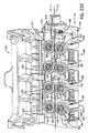
図18において、カセット300は、「装着済」または「使用中」位置として示されている。この「装着済」位置において、Yコネクタサポートアッセンブリ322は、Yコネクタ338が、軸駆動アッセンブリ324のガイドワイヤチャンネル364に対して位置決めされるように、下方向に回転する。この軸方向の位置決めにより、ガイドワイヤ軸駆動機構350および作動カテーテル軸駆動機構352の操作を介して、ガイドワイヤ301および作動カテーテル303をYコネクタ338内に移動するおよび/またはYコネクタ338内から移動することが可能になる。カバー356は、ガイドワイヤ軸駆動機構350および作動カテーテル軸駆動機構352の両方の上に重なる閉位置として示されている。図示されたように、カバー356はまた、ガイドワイヤチャンネル364および作動カテーテルチャンネル366を覆う。これにより、カバー356は、使用中に軸駆動アッセンブリ324の種々の構成要素が干渉することを防ぐ役割を果たす。 In FIG. 18, the
カバー356が閉位置に移動した後、ハンドル358の一部がカバー356を覆うような配置となるように、ハンドル358をおおよそ90°回転させる。以下に詳しく説明するように、ハンドル358を図18の閉位置まで回転させることで、ガイドワイヤ軸駆動機構350の係合表面および作動カテーテル軸駆動機構352の係合表面が共に移動し、ガイドワイヤ、作動カテーテルに係合する。 After the
また、カセット300が「装着済」位置に移動するとき、カバー384は、図18に示すように、閉位置に移動し、回転駆動機構380およびガイドワイヤチャンネル390の上に位置する。カバー356と同様に、カバー384は、使用中、回転駆動アッセンブリ326の種々の構成要素が干渉するのを防止する機能を果たす。一実施形態において、ユーザは、カセット300の種々の構成要素を「装填中」位置と「装填済」位置との間で移動させるように制御部(例えばワークステーション14に設けられた制御部)を操作する。また、カセット300の構成を、ユーザが、カセット300の種々の構成要素を「装填中」位置と「装填済」位置の間で、手動で移動できるように構成してもよい。 Further, when the
図18の「装着済」または「使用中」の構成において、Yコネクタ338の長手方向軸(および内部管腔)は、軸駆動アッセンブリのガイドワイヤチャンネル364と回転駆動アッセンブリ326のガイドワイヤチャンネ390と直線上に位置決めされる。この位置決めにより、ガイドワイヤの軸方向運動中にガイドワイヤが前進後退する、カセット300の後部からYコネクタ338を通りガイドカテーテルに入る通路が得られる。種々の実施形態において、トップデッキ354やシャーシ382、カバー356、カバー384などのカセット300の構成要素は、透明または半透明なプラスチックからなる。 In the “mounted” or “in use” configuration of FIG. Positioned on a straight line. This positioning provides a passage from the rear of the
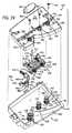
図19に、軸駆動アッセンブリ324の上面から見た分解斜視図を示す。図19は概して、軸駆動アッセンブリ324の構成要素を示す。ガイドワイヤ軸駆動機構350および作動カテーテル軸駆動機構352は、ベースプレート部318の上に配置され、トップデッキ354は、ガイドワイヤ軸駆動機構350と作動カテーテル軸駆動機構352との上で、ベースプレート部318の中央部360に固定される。よって、ガイドワイヤ軸駆動機構350および作動カテーテル軸駆動機構352は、軸駆動アッセンブリ324を組立てる際に、トップデッキ354およびベースプレート部318の中央部360によって区画されるチャンバー内におおよそ収められる。トップデッキ354は、複数の孔362を備えており、ガイドワイヤ軸駆動機構350および作動カテーテル軸駆動機構352の種々の部分を受ける。 FIG. 19 is an exploded perspective view as seen from the upper surface of the
軸駆動アッセンブリ350は、駆動要素400と、第1のローラアッセンブリ402と、第2のローラアッセンブリ404と、エンコーダアッセンブリ406として示されるガイドワイヤ軸方向運動センサアッセンブリとを備える。第1のローラアッセンブリ402および第2のローラアッセンブリ404は、共に筐体内416に装着されている。駆動要素400は、ドライブシャフト408と、ドライブホイール410と、ベアリング412と、スクリュー414とを備える。ドライブシャフト408は、ドライブシャフト408およびドライブホイール410が第2のキャプスタン306の回転に応じて回転するように、モータ駆動ベース部302の第2のキャプスタン306と係合する。第1の回転アッセンブリ402は、アイドラーホイールまたはローラ418と、ホイールハウジング420と、ベアリング422と、スプリング424とを備える。 The
ドライブホイール410は外表面または係合表面426を備え、ローラ418は外表面または係合表面428を備える。一般に、ガイドワイヤ軸駆動機構350が「使用中」または「係合済」位置(図22に示す)にあるとき、ガイドワイヤ301は、ドライブホイール410の係合表面426およびローラ418の係合表面428がガイドワイヤと係合可能なように、ドライブホイール410とローラ418との間に位置する。本実施形態において、係合表面426および係合表面428は、係合表面対を形成する。係合表面426と係合表面428によってガイドワイヤ301に与えられる力は、ドライブホイール410が、第2のキャプスタン306の回転によって起こるドライブシャフト408の回転に応じた軸方向運動を、ガイドワイヤ301に対して与えることができるような力である。この軸方向運動により、ユーザは、ワークステーション14に設置された制御部を操作することで、ガイドワイヤを前進および/または後退させることができる。ローラ418は、ホイールハウジング420内に回転可能に装着されており、ガイドワイヤ301を駆動するためにドライブホイール410が回転するのに伴い、自由に回転することができる。スプリング424は、ホイールハウジング420に力を与えるために付勢されており、これにより、ドライブホイール410に対してローラ418がガイドワイヤと係合する。スプリング424は、「係合済」位置にある係合表面426および係合表面428が、ガイドワイヤ301に対して適切な量の力を与えるように、選択および/または回転、調整される。他の実施形態において、追加の駆動要素を適宜加えて、ガイドワイヤに対して軸方向運動を与えるようにしてもよい。
第2のローラアッセンブリ404は、アイドラーホイールまたはローラ430と、ホイールハウジング432と、ベアリング434と、スプリング436とを備える。エンコーダアッセンブリ406は、シャフト438と、磁気カップリング440と、アイドラーホイールまたはローラ442と、ベアリング444と、スクリュー446とを備えている。ローラ430は、外表面または係合表面448を備えており、ローラ442は、外表面または係合表面450を備えている。 The
「係合済」位置において、ガイドワイヤ301は、ローラ430の係合表面448およびローラ442の係合表面450がガイドワイヤと係合可能なように、ローラ430とローラ443との間に配置される。この実施形態において、係合表面448と係合表面450は、係合表面対を形成する。係合表面448および係合表面450がガイドワイヤ301に与える力は、ドライブホイール410が、ローラ430および442を通過させてガイドワイヤ301を引っ張ることができるような力とする。このように、非能動またはアイドルローラ430と442対とによって、ガイドワイヤ301が支持され、カセット300の長手方向軸に沿った直線上にガイドワイヤ301が維持される。 In the “engaged” position, guidewire 301 is positioned between
ローラ430は、ホイールハウジング432内に回転可能に装着されており、ローラ442は、シャフト438に回転可能に装着されている。両方のローラ430および442ともに、ドライブホイール410がガイドワイヤ301に軸方向運動を与える際に回転自在にとなるように、装着されている。スプリング436は、ホイールハウジング432に力を与えるために付勢されており、これにより、ローラ442に対してローラ430がガイドワイヤ301と係合する。スプリング436の選択および/または回転、調整は、「係合済」位置にある係合表面448および係合表面450が、ガイドワイヤ301に対して適切な量の力を与え、ガイドワイヤがドライブホイール410により軸移動可能な状態で、ガイドワイヤを支持するようになされる。他の実施形態において、非能動またはアイドルローラ対を適宜追加して、ガイドワイヤに対して適切な指示や位置決めをしてもよい。一実施形態において、スプリング424およびスプリング436は、ホイール430および442によってガイドワイヤ301に付与される力が、ホイール410および418によってガイドワイヤ301に付与される力と実質的に同じになるように、選択または調整される。 The
エンコーダアッセンブリ406は、モータ駆動ベース部302内に設けられた磁気エンコーダを係合する磁気カップリング440を備える。磁気エンコーダは、ガイドワイヤの軸方向移動のパラメータ(例えば、速度、位置、加速度など)を測定するように構成されている。ローラ442が回転すると、シャフト438は回転し、磁気カップリング440を回転させる。磁気カップリング440が回転することで、モータ駆動ベース部302内の磁気エンコーダが回転する。ローラ442の回転は、ガイドワイヤ301の軸方向移動に関連しているため、モータ駆動ベース部302内の磁気エンコーダにより、処置中のガイドワイヤ301による軸方向移動量を測定することができる。この情報は、種々の目的に利用できる。例えば、ワークステーション14においてユーザにこの情報を表示する、患者の血管系内のガイドワイヤ位置を計算または推定することに使用する、ガイドワイヤを前進させる際のトラブルを示すアラートまたは警報のトリガーとする、などが挙げられる。 The
図19に示すように、第1のローラアッセンブリ402および第2のローラアッセンブリ404は共に、筐体416内に装着されている。筐体416は、第1のローラアッセンブリ402および第2のローラアッセンブリ404を共に支持する。以下に詳しく説明するように、第1のローラアッセンブリ402および第2のローラアッセンブリ404は、軸駆動アッセンブリ324が「装填中」位置に配置されるときに、それぞれドライブホイール410およびローラ442から離れる方向に移動する。これにより、ガイドワイヤ軸駆動機構350の対向する係合表面対の間にガイドワイヤ301を容易に設置することができる。この筐体416によって、軸駆動アッセンブリ324が「装填」位置にある時に、第1のローラアッセンブリ402および第2のローラアッセンブリ404が一緒になって(例えば同調)、それぞれドライブホイール410およびローラ442から離間するように移動することが可能になる。 As shown in FIG. 19, the
軸駆動アッセンブリ324はまた、作動カテーテル軸駆動機構352を備える。作動カテーテル軸駆動機構352は、駆動要素452および作動カテーテルエンコーダアッセンブリ454として示されている作動カテーテル軸運動センサアッセンブリを備える。駆動要素452は、ドライブシャフト456と、ドライブホイール458と、ベアリング460と、スクリュー462とを備える。ドライブシャフト456は、ドライブシャフト456およびドライブホイール458が、第1のキャプスタン304の回転に応じて回転するように、モータ駆動ベース部302の第1のキャプスタン304と係合するように、構成されている。エンコーダアッセンブリ454は、シャフト464と、ローラ466と、エンコーダリンケージ468と、スプリング470と、軸カップリング480とを備える。 The
ドライブホイール458は外表面または係合表面472を備えており、ローラ466は外表面または係合表面474を備えている。作動カテーテル軸駆動機構352が「係合済」位置にあるとき、作動カテーテルは、係合表面472および係合表面474が作動カテーテル303を係合可能なように、ドライブホイール458およびローラ466との間に配置されている。この実施形態において、係合表面472および474は、係合表面対を形成する。係合表面472および係合表面474が作動カテーテル303に与える力は、ドライブホイール458が、第1のキャプスタン304の回転によって起こるドライブシャフト456の回転に応じて作動カテーテルに対して軸方向運動を与えることができるような力である。この軸方向運動により、ユーザは、ワークステーション14に設置された制御部を操作することで、作動カテーテルを前進および/または後退させることができる。ローラ466は、シャフト464に回転可能に装着されており、作動カテーテルを駆動するためにドライブホイール458が回転するのに伴い、自由に回転することができる。 The
スプリング470は、リンケージ468の第1の端に連結されている。リンケージ468の第2の端は、トップデッキ354の内面から延在するポスト478を回転自在に連結する孔476を備えている。スプリング470は、「係合済」位置にある係合表面472および係合表面474が、作動カテーテル303に対して適切な量の力を与え、ドライブホイール458が作動カテーテルを軸方向に移動させることができるように、選択および/または回転、調整される。
エンコーダアッセンブリ454は、モータ駆動ベース部302内に配置された磁気エンコーダと係合する磁気カップリング480を備える。磁気カップリング480は、作動カテーテルの軸方向移動に関する特性(速度、位置、加速度など)を測定するように構成されている。ローラ466が回転すると、シャフト464が回転し、磁気カップリング480を回転させる。磁気カップリング480の回転により、モータ駆動ベース部302内の磁気エンコーダが回転する。ローラ466の回転は、作動カテーテル303の軸方向移動に関連しているため、モータ駆動ベース部302内の磁気エンコーダにより、処置中の作動カテーテルによる軸方向移動の量を測定することができる。この情報は、種々の目的に利用できる。例えば、ワークステーション14においてユーザにこの情報を表示する、患者の血管系内の作動カテーテル位置を計算または推定することに使用する、作動カテーテルを前進させる際のトラブルを示すアラートまたは警報のトリガーとするなどが挙げられる。 The
以下に詳しく説明するように、軸駆動アッセンブリ324が「装填中」位置にあるとき、ローラ466は、ドライブホイール458から離間するように移動する。これにより、作動カテーテルを作動カテーテル駆動機構352の対向する係合表面対に容易に配置可能となる。 As described in detail below, when the
一実施形態において、カセット300および/またはモータ駆動ベース部302は、作動カテーテル303の操作中はガイドワイヤ301の位置を固定し、ガイドワイヤ301の操作中は作動カテーテル303を固定するように構成されたロッキング機構を備えている。一実施形態において、このロッキング機構は、作動カテーテルが前進中は係合表面によってガイドワイヤに付与する力を増加し、ガイドワイヤが前進中は係合表面によって作動カテーテルに付与する力を増加するように機能する。 In one embodiment,
図19および図20において、トップデッキ354は、複数の円筒状スリーブ、第1のスリーブ482、第2のスリーブ484、第3のスリーブ486を備え、それぞれのスリーブは、トップデッキ354の内表面または下部表面から延在している。トップデッキ354はまた、複数の円筒状カラー、第1のカラー488、第2のカラー490、第3のカラー492をそなえ、それぞれのカラーは、トップデッキ354の上部表面から延在している。カラー488は、スリーブ482と軸方向に一直線となっている。カラー490は、スリーブ484と軸方向に一直線となっている。カラー492は、スリーブ486と軸方向に一直線となっている。それぞれのカラー488、490、492は、孔362を形成している。図示した実施形態において、スリーブ482とカラー488は、作動カテーテル駆動要素452を受けるように構成されており、スリーブ484とカラー490は、ガイドワイヤ駆動要素400を受けるように構成されており、スリーブ486とカラー492は、ガイドワイヤエンコーダアッセンブリ406を受けるように構成されている。トップデッキ354が軸駆動アッセンブリ324上に装着された後は、孔362からスクリュー414、446、462へアクセスできる。 19 and 20, the
トップデッキ354は、ガイドワイヤチャンネル364と直線上に位置し、その後端に設けられたカラー494を備える。カラー494は、回転駆動アッセンブリ326のシャーシ382から延在するフロントシャフト512を受けるように構成されている。カラー494は、フロントシャフト512(および連続する回転駆動アッセンブリ326の残りの部分)を軸駆動アッセンブリ324に対してガイドワイヤチャンネル390の長手方向軸を中心に回転可能に構成されている。一実施形態において、回転駆動アッセンブリ326は、カセット300の筐体316に対して回転せず、軸駆動アッセンブリ324は筐体316に対して回転しない。別の実施形態において、回転駆動アッセンブリ326および軸駆動アッセンブリ324は、カセット300の筐体316に対して回転する。 The
図20は、カセット300の底部斜視図であり、ガイドワイヤ軸駆動機構350および作動カテーテル軸駆動機構352上に装着されているトップデッキ354を示している。図20は、スリーブ482、484、486内で受けた作動カテーテル駆動要素452、ガイドワイヤ駆動要素400、ガイドワイヤエンコーダアッセンブリ406を示している。支持構造体496は、トップデッキ354の下部表面から延在している。スプリング470は、支持構造体496の一端で連結しており、これにより、スプリング470は、リンケージ468と支持構造体496との間で伸縮可能となっている。 FIG. 20 is a bottom perspective view of the
図示するように、ドライブシャフト408の下端には、キー溝498が備えられており、ドライブシャフト456には、キー溝500が備えられている。キー溝500は、第1のキャプスタンソケット310の1つの実施形態であり、キー溝498は、第2のキャプスタンソケット312の1つの実施形態である。キー溝500は、第1のキャプスタン304などのキャプスタンを受けるように構成されており、キー溝498は、第2のキャプスタン306などのキャプスタンを受けるように構成されている。第1のキャプスタン304および第2のキャプスタン306には、キーが施されており、キー溝500、498内で嵌合し、キャプスタン回転時にはシャフト456、408と係合、回転する。 As shown in the drawing, a
図示するように、ガイドワイヤエンコーダアッセンブリ406の磁気カップリング440は、磁石504の円形列を備えている。作動カテーテルエンコーダアッセンブリ454の磁気カップリング480は、磁石506の円形列を備えている。軸カップリング440、480は、モータ駆動ベース部302内に設けられた磁気エンコーダと係合する。モータ駆動ベース部302の磁気エンコーダは、適切な電子機器に連結されており、ローラ442、466の回転を検知、測定し、測定した回転に基づいてガイドワイヤ301および作動カテーテル303の軸方向運動を計算する。この実施形態では、磁気エンコーダを使用してガイドワイヤおよび作動カテーテルの軸方向運動を検知しているが、他のセンサを使用してもよい。一実施形態においては、ガイドワイヤの軸方向移動は、ガイドワイヤおよび/または作動カテーテルの表面が通り過ぎることを読み取って、ガイドワイヤおよび/または作動カテーテルの動きを検知する光学センサで検知してもよい。このような実施形態においては、光学センサは、LED光源と、ガイドワイヤおよび/または作動カテーテルの表面で反射した光を検出する検出部(例えば、相補型金属酸化膜半導体や他の光検出電気回路など)とを備えており、検出部で検出した光を解析して(例えば、デジタル信号処理によって)、ガイドワイヤおよび/または作動カテーテルの動きを特定する。別の実施形態においては、ガイドワイヤおよび/または作動カテーテルの表面に、ガイドワイヤの軸方向移動を特定するための検知用表示を備えてもよい。他の実施形態において、他のセンサ(例えば、リゾルバ、シンクロ、ポテンショメータなど)を使用して、ガイドワイヤおよび/または作動カテーテルの動きを検出してもよい。 As shown, the
カセット300はまた、一連の磁石508をガイドワイヤチャンネル364の下に有する。少なくとも1つの実施形態において、ガイドワイヤは磁性材料からなるので、磁石508は、ガイドワイヤと相互に作用可能である。本実施形態において、磁石508により生じた磁気引力によって、ガイドワイヤ301はガイドワイヤチャンネル364内に引き寄せられ、ユーザは、装填時にガイドワイヤ301を容易に配置することができる。ガイドワイヤが前進後退する際に、磁石508により生じた磁気引力によって、ガイドワイヤ301はガイドワイヤチャンネル364内に保持されることとなる。また、磁石508によって、ガイドワイヤ301を容易に直線上に(すなわち、ガイドワイヤチャンネル364の長手方向軸に平行に)保つことができ、ガイドワイヤ軸駆動機構350による軸方向移動を補助する。
図21は、「装着中」位置にある軸駆動アッセンブリ324の上面図を示しており、軸駆動アッセンブリ324に備えられたハンドル358(鎖線で示す)は、ガイドワイヤチャンネル364とおおよそ平行となるように、回転する。図22は、「装填済」または「使用中」位置にある軸駆動アッセンブリ324の上面図を示しており、ハンドル358は、ガイドワイヤチャンネル364とおおよそ垂直となるように、回転する。一般に、ハンドル358が図22に示す位置から図21に示す位置まで移動する際に、ガイドワイヤ軸駆動機構350と作動カテーテル軸駆動機構352の両方の係合表面は、それぞれ離間する方向に移動し、駆動機構内のホイール対間の距離は遠くなる。これにより、各駆動機構のホイール間の距離は十分なものとなり、ユーザは、ホイール間のチャンネルに、ガイドワイヤ301と作動カテーテル303とを配置できる。一般に、ハンドル358が図21に示す位置から図22に示す位置まで移動すると、ガイドワイヤ軸駆動機構350と作動カテーテル軸駆動機構352の両方の係合面は、それぞれお互いの方向に移動し、各駆動機構の係合表面は、それぞれガイドワイヤ310や作動カテーテルと係合する。 FIG. 21 shows a top view of the
図示する実施形態において、ハンドル358は、シャフト357に連結する。シャフト357はカム部359を備え、筐体416はカム表面417を備える。ハンドル358を図21に示す位置から図22に示す位置まで回転させると、シャフト357のカム部359はカム表面417に沿って移動し、それにより筐体416はガイドワイヤ301の方向に移動する。この動きにより、ガイドワイヤ301は、ドライブホイール410とローラ418間およびローラ430とローラ442間に傾倒されることとなる。ハンドル358を図22の位置まで移動すると、スプリング424と436は適切な張力に圧縮され、ドライブホイール410によってガイドワイヤ301をその長手方向軸に沿って移動させることが可能になる。 In the illustrated embodiment, the
また、筐体416は、リンケージ468に連結するタブ419を備える。これにより、リンケージ468は、筐体416が図21に示す位置に移動する際にポスト478を中心に回転する。この動きにより、ローラ466は、作動カテーテルドライブホイール458から離れる方向に移動する。筐体416が、図22に示す位置に移動する際に、ローラ466およびドライブホイール458の係合表面が作動カテーテル303に係合するように、ローラ466はカテーテルドライブホイール458に向かって移動する。一実施形態において、カセット300は、ワークステーション14に配置された制御部を操作することで、ユーザが軸駆動アッセンブリ324を「使用中」位置と「装填中」位置との間で移動可能とするように構成する。カセット300は、ユーザが軸駆動アッセンブリ324を「使用中」位置と「装填中」位置との間を手動で移動させるように構成してもよい The
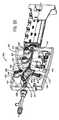
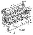
図23Aおよび23Bは、回転駆動アッセンブリ326の斜視図であり、開位置にあるカバー384を示している。回転駆動アッセンブリ326は、回転駆動機構380と、シャーシ382と、係合構造体386と、離脱アッセンブリ510とを備える。シャーシ382は、係合構造体386上に取り付けられ、回転駆動アッセンブリ326の種々の構成要素を取り付けるための部材である。シャーシ382は、フロントシャフト512およびリアシャフト514を備える。前述したように、フロントシャフト512は、トップデッキ354のカラー494内で回転可能に受けられており、リアシャフト514は、回転駆動機構380をジャーナル388に対して回転可能なように、カラー516内で回転可能に受けられている。図示するように、カラー516は、ジャーナル388を貫通して延在し、回転駆動機構380の回転に伴ってリアシャフト514がカラー516内で回転するように、ジャーナル388によって支持されている。カラー516は、凹部またはジャーナル388内に形成されたスロット内に配置される。別の実施形態において、リアシャフト514は、回転駆動機構380の回転に伴ってリアシャフト514がジャーナル388の凹部内またはスロット内で回転するように、ジャーナル388と直接接触してもよい。ガイドワイヤチャンネル390は、シャーシ382の長さ方向に延在し、フロントシャフト512およびリアシャフト514を貫通している。 23A and 23B are perspective views of the
回転駆動機構380は、ドライブギヤ520と係合する回転ベベルギア518を備えている。ベベルギア518は、ベベルギア518の回転によりシャーシ382が回転するように、シャーシ382のフロントシャフト512に剛接合されている。ドライブギヤ520は、モータ駆動ベース部302内に配置された回転アクチュエータに連結されており、ベベルギア518と係合している。モータ駆動ベース部302内の回転アクチュエータが回転することにより、ドライブギヤ520が回転し、これにより、ベベルギア518が回転し、さらには回転駆動機構380を回転させる。回転駆動機構380は、フロントシャフト512とトップデッキ354との間とリアシャフト514とジャーナル388との間とを回転可能に接続することで、ガイドワイヤチャンネル390の長手方向軸を中心に回転可能となる。ベベルギア518はさらに、ガイドワイヤチャンネル390の軸方向と直線上に配置されたスロット519を備える。スロット519により、ユーザは、ベベルギア518を通さずに、ガイドワイヤ301を垂直に落下させることで、ガイドワイヤ301をガイドワイヤチャンネル390内に配置することができる。一実施形態において、回転駆動アッセンブリ326は、ガイドワイヤおよび/または他の回転駆動アッセンブリ326の構造体の回転の特性(例えば、速度、位置、加速度など)を測定するように構成された、1つあるいはそれ以上のセンサを備えている。ガイドワイヤの回転を測定するセンサは、ガイドワイヤおよび/または作動カテーテルの軸方向運動を測定するセンサに関連して説明した磁気エンコーダおよび/または光学センサを備えていてもよい。しかし、任意の好適なセンサ(例えばレゾルバ、シンクロ、ポテンショメータなど)を使用して、ガイドワイヤの回転を検出してもよい。 The
図23Bに、実施形態例による係合構造体386を示す。図中に示すように、係合構造体386は、4対のアイドラーホイールまたはローラを備えている。ローラの各対は、固定ホイール522および係合ホイール524からなる。固定ホイール522は、固定ポスト530を介してシャーシ382に回転可能に連結されている。各係合ホイール524は、係合ホイールアッセンブリの一部を構成している。各係合ホイールアッセンブリ523は、ピボットヨーク532とスプリング536を備える。各係合ホイールは、マウンティングポスト538を介してピボットヨーク532に装着されている。各ピボットヨーク532は、固定ポスト534を介してシャーシ382に回転可能に連結されている。 FIG. 23B illustrates an
各固定ホイール522は外表面または係合表面526を備えており、各係合ホイール524は外表面または係合表面528を備えている。概して、図23Bは、「使用中」または「装填済」位置にある係合構造体386を示している。「装填済」位置において、ガイドワイヤ301は、係合表面526および528がガイドワイヤ301と係合するように、固定ホイール522と係合ホイール524との間に設けられている。本実施形態において、各ローラ対の係合表面526と係合表面528は、係合表面の対を形成する。係合表面526および528によってガイドワイヤ301に加えられる力は、回転駆動アッセンブリ326の回転に伴いガイドワイヤをその長手方向軸を中心に回転させるのに十分な力とする。また、係合表面526および528に対してガイドワイヤ301に加えられる力は、ガイドワイヤ軸駆動機構350によってガイドワイヤが軸方向移動するのに十分な力とする。 Each fixed
スプリング536は、ピボットヨーク532に力を加えるように付勢されており、これにより、各係合ホイール524が対向する固定ホイール522と係合する。ピボットヨーク532をおおよそL字型とすることで、スプリング536がガイドワイヤ301の長手方向軸に合わせて配置可能となり、係合ホイール524、固定ホイール522、ガイドワイヤが係合することとなる。これにより、スプリング536がガイドワイヤの長手方向軸に対して垂直となるように配置された場合に比べて、回転駆動アッセンブリ326の横方向の寸法が小さくなる。スプリング536は、「係合済」位置にある係合表面526および係合表面528が、ガイドワイヤに対して適切な量の力を与えるように、選択および/または回転、調整される。 The
カセット300はまた、一連の磁石540をガイドワイヤチャンネル390の下に備える。少なくともいくつかの実施形態において、ガイドワイヤは磁性材料からなるので、磁石540は、ガイドワイヤと相互に作用可能である。本実施形態において、磁石540により生じた磁気引力によって、ガイドワイヤ301はガイドワイヤチャンネル390内に引き寄せられ、ユーザは、装填時にガイドワイヤ301を容易に配置することができる。また、ガイドワイヤが前進後退する際に、磁石540により生じた磁気引力によって、ガイドワイヤ301はガイドワイヤチャンネル390内に保持されることとなる。さらに、磁石540によって、ガイドワイヤ301を容易に直線上に(すなわち、ガイドワイヤチャンネル390の長手方向軸に平行に)保つことができ、ガイドワイヤ軸駆動機構350による軸方向移動を補助する。
回転駆動アッセンブリはまた、離脱アッセンブリ510を備える。離脱アッセンブリ510は、段付きカラー542、ベースプレート部544、スプリング546を備える。段付きカラー542はベースプレート部544に連結し、スプリング546は少なくともシャーシ382の一端およびベースプレート部544の他端と連結する。段付きカラー542は、ガイドワイヤチャンネル390と軸直線上に配置されたスロット548を備える。スロット519と同様に、スロット548を設けることにより、ユーザは、段付きカラー542を通さずに、ガイドワイヤ301を垂直に落下させることで、ガイドワイヤ301をガイドワイヤチャンネル390内に配置することができる。ベースプレート部544は、そのベースプレート部544によって形成された面とおおよそ垂直に延在する複数の係合アーム550を備える。 The rotary drive assembly also includes a
概して、離脱アッセンブリ510によって、係合ホイール524は固定ホイール522から離れるように移動可能となる。図24および25において、図25は、「装填中」位置にある回転駆動アッセンブリ326の上面図を示しており、図24は、「装填済」または「使用中」位置にある回転駆動アッセンブリ326の上面図を示している。係合ホイール524をガイドワイヤ301から離脱させるには、軸方向に作用する力(図25に矢印で示す)を段付きカラー542に加える。これにより、ベースプレート部544は、矢印で示す方向であるカセット300前方向に移動する。ベースプレート部544が前方向に移動することで、スプリング546が圧縮され、係合アーム550がピボットヨーク532と接触する。係合アーム550とピボットヨーク532との接触により、スプリング536が圧縮され、ピボットヨーク532は、固定ポスト534を中心に回転する。ピボットヨーク532が回転すると、係合ホイール524が固定ホイール522から離れるように移動する。図25に示すように、これにより、係合ホイール524と固定ホイール522との間に十分なスペースが生じ、ユーザは、ガイドワイヤ301をガイドワイヤチャンネル390内に設置できる。 In general, the
軸方向の力が段付きカラー542から取り除かれると、係合ホイール524は、図25内の位置から図24に示す「係合済」位置に移動する。軸方向の力が取り除かれると、スプリング546およびスプリング536は伸張し、係合アーム550はピボットヨーク532から離脱する。ピボットヨーク532は、固定ポスト534を中心に反時計回りに回転し、係合ホイール524をガイドワイヤチャンネル390方向に戻し、これにより、固定ホイール522の係合表面526および係合ホイール524の係合表面528がガイドワイヤ301と係合する。 When the axial force is removed from the stepped
一実施形態において、ユーザは、ワークステーション14に設けられた制御部を操作して、回転駆動アッセンブリ326を「使用中」位置と「装填中」位置との間で移動させる。本実施形態において、回転駆動アッセンブリ326は、ガイドワイヤチャンネル390がおおよそ上方向を向き、ガイドワイヤを容易に装填や取り外すことができるように、自動的に回転する。図示する実施形態において、シャーシ382は、段付きカラー542に対して回転する。本実施形態おいて、回転駆動アッセンブリ326が「装填中」位置にある場合、係合構造体386の係合表面とガイドワイヤチャンネル390の係合表面によって形成される通路は、段付きカラー542のスロット548と一直線上に並ぶ。モータ駆動ベース部302はまた、ユーザがワークステーション14に設けられた制御部を操作することで段付きカラー542に対して軸方向の力を加える構造体(例えば2つのロッドなど)を備えていてもよい。この構造体は、段付きカラー542に軸方向の力を加え、係合構造体386をガイドワイヤから離脱させる。次に、カバー384が閉位置から開位置に移動し、ユーザがガイドワイヤチャンネル390にアクセスできるようにし、ガイドワイヤを取り外すか、装着する。一実施形態において、カセット300および/またはモータ駆動ベース部302は、モータや、ユーザがワークステーション14に設けられた制御部を操作することに応じてカセット300のカバーを開くその他のアクチュエータを備える。 In one embodiment, the user operates a controller provided on the
図26は、図18中において対応する断面線で示す回転駆動アッセンブリ326の断面の図である。図26は、ガイドワイヤチャンネル390内にあるガイドワイヤ301を示している。図26に示すように、カバー384が閉位置にあるとき、タブ396はガイドワイヤチャンネル390上に配置される。図26に示すように、タブ396によって、ベースプレート部544で形成される面に垂直な方向の(この拘束方向は、図26で示す配置において上下方向)ガイドワイヤ301の動作を制限するため、ガイドワイヤ301は、ガイドワイヤチャンネル390内に保持されることとなる。ガイドワイヤ301は、その一面において固定ホイール522の係合表面526と係合し、その他面において係合ホイール524の係合表面528と係合する。 26 is a cross-sectional view of the
図27は、図18中において対応する断面線で示す軸駆動アッセンブリ324の断面の図である。図27は、チャンネル364内にあるガイドワイヤ301を示している。ガイドワイヤ301は、その一面において駆動ホイール410の係合表面426と係合し、その他面においてローラ418の係合表面428と係合する。 FIG. 27 is a cross-sectional view of the
ある状況下において、回転駆動アッセンブリ326をカセット300から取り外すことが望ましい場合がある。図28Aから図28Cにおいて、カセット300は、回転駆動アッセンブリ326(図28A〜図28Cの鎖線で概略を示す)をカセット300から取り外すことが可能なように構成されている。このような一実施形態において、カセット300はジャーナル388を備え、回転駆動機構380はジャーナル388と回転可能に連結されている。この実施形態において、ジャーナル388は、ガイドワイヤを患者から外すことなくおよび/またはカセット300をベース部302から取り外すことなく、ジャーナル388と回転駆動機構380の両方が筐体316から取り外せるように、筐体316と開放可能に連結されている。このような一実施形態において、筐体316からジャーナル388を開放することに続いて、ユーザは、ジャーナル388および回転駆動機構380の両方をガイドワイヤの近位端上で取り外すこと(例えば、引く、ずらすなど)ができる。 Under certain circumstances, it may be desirable to remove the
一実施形態において、ジャーナル388はスロット552を備え、ベースプレート部318は開放ボタン554を備える。開放ボタン554は傾斜路556と連結しており、傾斜路556はくさび形状端558を備えている。図28Aで示すように、くさび形状端558は、スロット552を通過し、ジャーナル388をベースプレート部318と連結している。下方向の力が開放ボタン554に加わると、くさび形状端558は、スロット552から離脱し、回転駆動アッセンブリ326およびジャーナル388をベースプレート部318から分離できるようにする。 In one embodiment, the
次に、回転駆動アッセンブリ326はガイドワイヤ301から離脱する。以下に説明するように、図24および図25において、段付きカラー542に軸方向の力を加えると、係合構造体386はガイドワイヤから離脱する。係合構造体386がガイドワイヤ301から離脱すると、ガイドワイヤがガイドワイヤチャンネル390内で自由にずれる状態で、回転駆動アッセンブリ326は、ガイドワイヤの近位端上方に移動することが可能になる。例えばベッドシステム12が受電できなくなり、回転駆動ベース部302が回転駆動アッセンブリを「装填中」位置に配置できなくなった場合、回転駆動アッセンブリ326をカセット300から取り外すことが必要になる。この場合、回転駆動アッセンブリ326を取り外すことによって、ユーザは、患者からガイドワイヤおよび作動カテーテルを手動で取り除く、または手動で処置を終了することが可能になる。 Next, the
一実施形態において、カセット300は、1回のみの使用あるいは使い捨てのカセットであり、カテーテル処置に対してカセットを1回を超えて使用することが機能的に不可能なように作用する使用制限要素を備えている。一実施形態において、使用制限要素は、カセット300が一度取り除かれた後に、モータ駆動ベース部302のキャプスタンに再び装着されることを防止する、容易に破損する部材であり、1つあるいはそれ以上のキャプスタンソケット内に設けられている。別の実施形態において、使用制限要素は、カセット300が以前に使用されたかどうかを示す、RFID受信機と通信するRFIDタグである。別の実施形態において、使用制限要素は、使用前にスキャンしなければならない、カセット300と関連付いたバーコードを備えている。スキャンされたバーコードが既に使用済のカセットに関連付いている場合、カセットの再使用は妨げられる。 In one embodiment,
さらに、本発明の種々の側面を有する変形例や代わりの実施形態は、本明細書に関する分野の当業者であれば明らかなことである。従って、本明細書は、実例として考えられるべきであり、本願を実施する一般的な方法を当業者に教示する目的でなされたものである。上記した任意の実施形態例の任意の特徴、要素、構成要素は、単体で使用することもできるし、上記した他の任意の実施形態の任意の特徴、要素、構成要素と組み合わせて使用することもできる。本明細書で示し説明した本願の形態は、現在における好適な実施形態として捉えるべきであることが理解できる。本願の明細書で得られる利点を有する当業者にとって明らかなように、要素や材料は、本明細書内で示し、説明したものと置き換えることができ、部品や処理を入れ替えてもよく、本発明の任意の特徴を独立して使用することもできる。以下の請求の範囲で述べる発明の要点や範囲から逸脱しない範囲で、本明細書内で説明した要素に対して変更を加えることもできる。 Moreover, variations and alternative embodiments having various aspects of the invention will be apparent to those skilled in the art to which this specification pertains. Accordingly, this description is to be construed as illustrative, and is for the purpose of teaching those skilled in the art the general manner of carrying out the present application. Any feature, element, or component of any of the above described exemplary embodiments can be used alone or in combination with any feature, element, or component of any of the other above-described embodiments. You can also. It can be appreciated that the form of the application shown and described herein is to be taken as the presently preferred embodiment. It will be apparent to those skilled in the art having the benefit of the present specification that the elements and materials may be interchanged with those shown and described herein, and the parts and processes may be interchanged. Any of the features can also be used independently. Changes may be made to the elements described within this specification without departing from the spirit and scope of the invention as set forth in the claims below.
Claims (64)
Translated fromJapanese筐体と、
前記筐体に支持され、ガイドワイヤと釈放可能に係合し、また前記ガイドワイヤの長手方向軸に沿って前記ガイドワイヤを駆動するよう構成した第1軸駆動機構と、
前記筐体に支持され、作動カテーテルと釈放可能に係合し、また前記作動カテーテルの長手方向軸に沿って前記作動カテーテルを駆動する第2軸駆動機構と、
前記筐体に支持され、前記ガイドワイヤの長手方向軸線の周りに前記ガイドワイヤを回転するように構成した回転駆動機構であり、ガイドワイヤと釈放可能に係合する係合構造体を有し、前記係合構造体は、ガイドワイヤが前記第1軸駆動機構により軸方向に移動するとともにガイドワイヤの長手方向軸線の周りにガイドワイヤが回転するのに十分な力を加えるよう構成した、該回転駆動機構と
を備えた、該カセットにおいて、
前記第1軸駆動機構、前記第2軸駆動機構、および前記回転駆動機構は、少なくとも1つのアクチュエータと作動可能に連結し、前記アクチュエータは、前記ガイドワイヤを駆動し、前記作動カテーテルを駆動し、また前記ガイドワイヤを回転するためのエネルギーを供給するよう構成した、ことを特徴とするカセット。A cassette for use in a robotic catheter system configured to be coupled to a base portion,
A housing,
A first shaft drive mechanism supported by the housing, releasably engaged with the guide wire, and configured to drive the guide wire along a longitudinal axis of the guide wire;
A second shaft drive mechanism supported by the housing, releasably engaged with the working catheter, and driving the working catheter along a longitudinal axis of the working catheter;
A rotational drive mechanism supported by the housing and configured to rotate the guide wire around a longitudinal axis of the guide wire, and having an engagement structure that releasably engages with the guide wire; The engagement structure is configured to apply a force sufficient for the guide wire to move axially by the first shaft drive mechanism and to rotate the guide wire about the longitudinal axis of the guide wire. In the cassette comprising a drive mechanism,
The first shaft drive mechanism, the second shaft drive mechanism, and the rotation drive mechanism are operatively coupled to at least one actuator, the actuator driving the guide wire, driving the actuation catheter; The cassette is configured to supply energy for rotating the guide wire.
前記回転駆動機構に重なり合う閉位置から前記回転駆動機構を露出させる開位置に移動可能な第1のカバーと、
前記第1カバーが前記閉位置にあるとき、前記ガイドワイヤの移動を拘束するよう作用する拘束構造体と、
を備えた、カセット。The cassette of claim 1, further comprising:
A first cover movable from a closed position overlapping the rotation drive mechanism to an open position exposing the rotation drive mechanism;
A restraining structure that acts to restrain movement of the guide wire when the first cover is in the closed position;
With a cassette.
前記第1軸駆動機構に重なり合う閉位置から前記第1軸駆動機構を露出させる開位置に移動可能な第2カバーであり、前記第2のカバーから突出する少なくとも1つのタブを有する、該第2のカバー
を備え、
前記回転駆動機構は、側壁付きの第1チャンネルを有し、また前記第1軸駆動機構は、側壁付きの第2チャネルを有し、
前記チャンネルの側壁は、第1の方向へのガイドワイヤの動きを拘束し、
前記第1カバーおよび前記第2カバーが閉位置にあるとき、前記第1カバーの少なくとも1つのタブ、および前記第2カバーの少なくとも1つのタブが、第2の方向へのガイドワイヤの動きを拘束する構成とした、カセット。The cassette of claim 3, further comprising:
A second cover that is movable from a closed position that overlaps the first shaft drive mechanism to an open position that exposes the first shaft drive mechanism, and has at least one tab protruding from the second cover; With a cover
The rotational drive mechanism has a first channel with a sidewall, and the first shaft drive mechanism has a second channel with a sidewall,
The side wall of the channel constrains the movement of the guide wire in the first direction;
When the first cover and the second cover are in the closed position, the at least one tab of the first cover and the at least one tab of the second cover constrain the movement of the guide wire in the second direction. A cassette that is configured to
前記磁石は、前記ガイドワイヤに作用し、前記第1チャンネルまたは前記第2チャンネルのうち少なくとも一方の内部にガイドワイヤを保持する構成とした、カセット。5. The cassette according to claim 4, further comprising at least one magnet disposed below at least one of the first channel and the second channel,
The cassette, wherein the magnet acts on the guide wire and holds the guide wire in at least one of the first channel and the second channel.
ガイドワイヤの長手方向軸線の周りにガイドワイヤを回転させるとともに、ガイドワイヤを前記第1軸駆動機構により軸方向に移動するのに十分な力を、第1係合表面および第2係合表面が加える構成とした、カセット。The cassette according to claim 1, wherein the engagement structure of the rotational drive mechanism has a first engagement surface and a second engagement surface to releasably engage the guide wire,
The first engagement surface and the second engagement surface have sufficient force to rotate the guide wire about the longitudinal axis of the guide wire and to move the guide wire in the axial direction by the first shaft drive mechanism. A cassette to be added.
前記第1支持カラーおよび第2支持カラーは、それぞれスロットを有し、
前記第1係合表面および前記第2係合表面は、前記第1支持カラーおよび第2支持カラー双方のスロットに整列する通路を画定する構成とした、カセット。The cassette according to claim 7, wherein the engagement structure of the rotation drive mechanism is supported by a first support collar and a second support collar,
The first support collar and the second support collar each have a slot;
The cassette wherein the first engagement surface and the second engagement surface are configured to define a passage that is aligned with a slot in both the first support collar and the second support collar.
前記第1係合表面対は、前記第1係合表面対と前記ガイドワイヤとの間の係合により、前記ガイドワイヤに対して軸方向の運動を与え、
前記第2軸駆動機構は、前記作動カテーテルに釈放可能に係合する第2係合表面対を有し、
前記第2軸駆動機構は、前記第2係合表面対と前記作動カテーテルとの間の係合により、前記作動カテーテルに対して軸方向の運動を与える構成とした、カセット。2. The cassette according to claim 1, wherein the first shaft driving mechanism has a pair of first engagement surfaces that releasably engage with the guide wire,
The first engagement surface pair imparts axial movement relative to the guide wire by engagement between the first engagement surface pair and the guide wire;
The second shaft drive mechanism has a second pair of engagement surfaces that releasably engage the actuation catheter;
The cassette, wherein the second shaft driving mechanism is configured to impart an axial motion to the working catheter by engagement between the second pair of engagement surfaces and the working catheter.
前記カバーが開く際、前記第1係合表面対が前記ガイドワイヤから離脱し、また前記第2係合表面対が前記作動カテーテルから離脱する構成とした、カセット。10. The cassette according to claim 9, further movable from a closed position overlapping the first shaft driving mechanism and the second shaft driving mechanism to an open position exposing the first shaft driving mechanism and the second shaft driving mechanism. Equipped with a cover,
The cassette is configured such that when the cover is opened, the first engagement surface pair is detached from the guide wire, and the second engagement surface pair is detached from the working catheter.
前記ガイドワイヤの軸方向の動きに関する特性を測定するように構成した少なくとも第1センサと、
前記作動カテーテルの軸方向の動きに関する特性を測定するように構成した少なくとも第2センサと
を、備えた、カセット。The cassette of claim 1, further comprising:
At least a first sensor configured to measure characteristics relating to axial movement of the guidewire;
A cassette comprising: at least a second sensor configured to measure a characteristic relating to axial movement of the working catheter.
Yコネクタを支持するYコネクタ支持アッセンブリを備え、
前記Yコネクタ支持アッセンブリは、前記第1軸駆動機構の長手方向軸線に対して角度をなす位置に移動可能であり、これにより、前記ガイドワイヤおよび作動カテーテルを前記Yコネクタに容易に装填可能とした、カセット。The cassette of claim 1, further comprising:
A Y connector support assembly for supporting the Y connector;
The Y connector support assembly can be moved to a position that makes an angle with respect to the longitudinal axis of the first shaft drive mechanism, so that the guide wire and the working catheter can be easily loaded into the Y connector. ,cassette.
ガイドカテーテルを支持するよう構成したガイドカテーテルサポートを備え、
前記ガイドカテーテルサポートは、前記カセットから突出して、前記カセットから離間した位置で前記ガイドカテーテルを支持する構成とした、カセット。The cassette of claim 1, further comprising:
A guide catheter support configured to support the guide catheter;
The cassette, wherein the guide catheter support protrudes from the cassette and supports the guide catheter at a position spaced from the cassette.
前記回転駆動機構および前記第1軸駆動機構に重なり合う閉位置から前記回転駆動機構および前記第1軸駆動機構を露出させる開位置に移動可能なカバーであり、前記第1カバーから突出する少なくとも1つのタブを有する、該カバーを備え、
前記回転駆動機構は、側壁付きの第1チャンネルを有し、また前記第1軸駆動機構は、側壁付きの第2チャンネルを有し、
前記チャンネルの側壁は、第1の方向へのガイドワイヤの移動を拘束し、さらに
前記第1カバーが閉位置にあるとき、前記第1カバーの少なくとも1つのタブが、第2の方向へのガイドワイヤの移動を拘束する構成とした、カセット。The cassette of claim 1, further comprising:
A cover movable from a closed position overlapping the rotation drive mechanism and the first shaft drive mechanism to an open position exposing the rotation drive mechanism and the first shaft drive mechanism, and at least one protruding from the first cover Comprising a cover having a tab;
The rotational drive mechanism has a first channel with a sidewall, and the first shaft drive mechanism has a second channel with a sidewall,
The side walls of the channel constrain the movement of the guide wire in a first direction, and when the first cover is in the closed position, at least one tab of the first cover is guided in the second direction. A cassette configured to restrain the movement of the wire.
ユーザインターフェースと、
モータ制御部と、
モータカプラーを有するカセットベース部と、
前記モータカプラーと連結する少なくとも1つのモータと
前記カセットベース部に取り外し可能に装着し、また前記モータカプラーに作動可能に連結した、カセットと
を備え、前記カセットは、
ガイドワイヤと釈放可能に係合し、またガイドカテーテルを介して前記ガイドワイヤの長手方向軸線に沿って前記ガイドワイヤを駆動するよう構成した第1軸駆動機構と、
作動カテーテルと釈放可能に係合し、ガイドカテーテルを介して前記作動カテーテルの長手方向軸線に沿って前記作動カテーテルを駆動するよう構成した第2軸駆動機構と、および
前記ガイドワイヤと釈放可能に係合し、前記ガイドワイヤの長手方向軸線の周りに前記ガイドワイヤを回転するよう構成した第1回転駆動機構であって、前記ガイドワイヤと釈放可能に係合するよう構成した第1グリップ表面および第2グリップ表面を有し、前記第1グリップ表面および第2グリップ表面は、前記回転駆動機構の回転に際しガイドワイヤを回転させるとともに、前記第1軸駆動機構により前記ガイドワイヤの長手方向軸線に沿って独立して移動するのに十分な力をガイドワイヤに加えるよう構成した、該第1回転駆動機構と
を備える構成とした、ロボット血管カテーテルシステム。In a robotic vascular catheter system,
A user interface;
A motor controller;
A cassette base having a motor coupler;
At least one motor coupled to the motor coupler, and a cassette detachably mounted on the cassette base and operably coupled to the motor coupler, the cassette comprising:
A first shaft drive mechanism configured to releasably engage the guide wire and to drive the guide wire along a longitudinal axis of the guide wire via a guide catheter;
A second shaft drive mechanism configured to releasably engage the actuation catheter and drive the actuation catheter along a longitudinal axis of the actuation catheter via the guide catheter; and releasably associated with the guide wire And a first rotational drive mechanism configured to rotate the guide wire about a longitudinal axis of the guide wire, wherein the first grip surface configured to releasably engage the guide wire and The first grip surface and the second grip surface rotate the guide wire when the rotation drive mechanism is rotated, and the longitudinal axis of the guide wire is driven by the first shaft drive mechanism. The first rotation drive mechanism is configured to apply sufficient force to the guide wire to move independently. Robot vascular catheter system.
前記作動カテーテルの操作中にガイドワイヤの位置を固定し、また前記ガイドワイヤの操作中に前記作動カテーテルの位置を固定するよう構成したロッキング機構を備えた、システム。The system of claim 21, further comprising:
A system comprising a locking mechanism configured to fix a position of a guide wire during operation of the working catheter and to fix a position of the working catheter during operation of the guide wire.
筐体と、
前記筐体に支持し、ガイドワイヤと釈放可能に係合し、また前記ガイドワイヤの長手方向軸線に沿って前記ガイドワイヤを駆動するよう構成した第1軸駆動機構と、
前記筐体に支持し、作動カテーテルと釈放可能に係合し、また前記作動カテーテルの長手方向軸線に沿って前記作動カテーテルを駆動するよう構成した第2軸駆動機構と、および
前記ガイドワイヤの長手方向軸線の周りに前記ガイドワイヤを回転するよう構成した第1回転駆動機構であって、前記ガイドワイヤと釈放可能に係合するよう構成した回転構造体を有し、前記回転構造体は、前記回転構造体が回転する際にガイドワイヤの長手方向軸線の周りにガイドワイヤを回転させるとともに、ガイドワイヤを前記第1軸駆動機構により軸方向に移動できるようにするのに十分な力を加えるよう構成した、該第1回転駆動機構と
を備え、
前記第1および第2の軸駆動機構並びに回転駆動機構は、前記カセットの外部にあるドライブと連結可能とした、ことを特徴とするカテーテル駆動カセット。In the catheter drive cassette configured to be coupled to the motor drive base,
A housing,
A first shaft drive mechanism supported on the housing, releasably engaged with the guide wire, and configured to drive the guide wire along a longitudinal axis of the guide wire;
A second shaft drive mechanism supported on the housing, releasably engaged with the working catheter, and configured to drive the working catheter along a longitudinal axis of the working catheter; and a length of the guide wire A first rotational drive mechanism configured to rotate the guide wire around a directional axis, the rotational structure configured to releasably engage with the guide wire; As the rotating structure rotates, the guide wire is rotated about the longitudinal axis of the guide wire and sufficient force is applied to allow the guide wire to be moved in the axial direction by the first shaft drive mechanism. Comprising the first rotational drive mechanism configured,
The catheter drive cassette, wherein the first and second shaft drive mechanisms and the rotary drive mechanism can be connected to a drive outside the cassette.
前記カバーが開く際、前記ガイドワイヤを容易に取り外すための垂直通路に整列するよう、前記回転駆動機構を自動的に位置決めするカテーテル駆動カセット。37. The catheter drive cassette according to claim 36, further comprising a cover that is movable from a closed position that overlaps the first rotation drive mechanism to an open position that exposes the first rotation drive mechanism,
A catheter drive cassette that automatically positions the rotational drive mechanism to align with a vertical passageway for easy removal of the guidewire when the cover is opened.
前記回転アッセンブリは、前記回転駆動機構の第1係合表面および第2係合表面が、前記回転アッセンブリサポート内に配置されるスロットと同一平面内の通路を形成する装填位置を有する構成とした、カテーテル駆動カセット。49. The catheter drive cassette of claim 48, wherein the rotary drive mechanism comprises a rotary assembly rotatably supported within a rotary assembly support,
The rotation assembly has a configuration in which the first engagement surface and the second engagement surface of the rotation drive mechanism have a loading position in which a passage in the same plane as a slot disposed in the rotation assembly support is formed. Catheter drive cassette.
前記ガイドカテーテルの長手方向軸線の周りに前記ガイドカテーテルを回転させる駆動機構と
を備えた、カテーテル駆動カセット。The catheter drive cassette according to claim 51, further comprising a drive mechanism for moving the guide catheter support in a direction along a longitudinal axis of the guide catheter;
A catheter drive cassette comprising: a drive mechanism for rotating the guide catheter about a longitudinal axis of the guide catheter;
カセットをモータ駆動ベース部に連結するステップと、
ガイドカテーテルをガイドカテーテルサポートに固定するステップと、
ガイドワイヤを前記ガイドカテーテル内に前進させるステップと、
作動カテーテルを、前記ガイドワイヤに沿って前記ガイドカテーテル内に前進させるステップと、
前記ガイドワイヤを前記カセット内の第1軸駆動機構内に配置するステップと、
少なくとも1対の係合面を有するよう前記カセット内に設けた回転駆動機構の内部に、前記ガイドワイヤを配置する回転駆動機構内配置ステップであって、前記ガイドワイヤを前記少なくとも1対の係合面によって釈放可能に係合するようにした、該回転駆動機構内配置ステップと、
前記作動カテーテルを前記カセット内の第2の軸駆動機構内に配置するステップと、および
前記ガイドワイヤおよび前記作動カテーテルを位置決めする位置決めステップであって、
前記ガイドワイヤをその長手方向軸線に沿って駆動し、
前記作動カテーテルをその長手方向軸線に沿って駆動し、また
前記ガイドワイヤをその長手方向軸線の周りに回転させ、前記ガイドワイヤの回転は、ガイドワイヤの軸方向移動とは独立して行うことができるようにした、該位置決めステップと
を有する、ロボット血管カテーテルシステムの作動方法。A method for operating a robotic vascular catheter system comprising:
Connecting the cassette to the motor drive base;
Securing the guide catheter to the guide catheter support;
Advancing a guide wire into the guide catheter;
Advancing a working catheter along the guidewire into the guide catheter;
Placing the guide wire in a first shaft drive mechanism in the cassette;
A step of arranging the guide wire inside a rotary drive mechanism provided in the cassette so as to have at least one pair of engaging surfaces, wherein the guide wire is engaged with the at least one pair of engagement surfaces; An arrangement step in the rotary drive mechanism that is releasably engaged by a surface;
Positioning the working catheter in a second shaft drive mechanism in the cassette; and positioning the guide wire and the working catheter,
Driving the guidewire along its longitudinal axis;
The actuating catheter is driven along its longitudinal axis, and the guide wire is rotated about its longitudinal axis, and the rotation of the guide wire is performed independently of the axial movement of the guide wire. A method of operating a robotic vascular catheter system comprising the positioning step.
前記プラスチックカバーは、前記モータ駆動ベース部から延在する複数のモータカプラーに整列する予め形成した孔を有する構成とした、方法。58. The method of claim 57, further comprising the step of covering a plastic cover on the motor base.
The method wherein the plastic cover has a pre-formed hole aligned with a plurality of motor couplers extending from the motor drive base.
Applications Claiming Priority (3)
| Application Number | Priority Date | Filing Date | Title |
|---|---|---|---|
| US5093308P | 2008-05-06 | 2008-05-06 | |
| US61/050,933 | 2008-05-06 | ||
| PCT/US2009/042720WO2009137410A1 (en) | 2008-05-06 | 2009-05-04 | Catheter system |
Related Child Applications (1)
| Application Number | Title | Priority Date | Filing Date |
|---|---|---|---|
| JP2014194255ADivisionJP6004545B2 (en) | 2008-05-06 | 2014-09-24 | Catheter system |
Publications (2)
| Publication Number | Publication Date |
|---|---|
| JP2011519678Atrue JP2011519678A (en) | 2011-07-14 |
| JP5723766B2 JP5723766B2 (en) | 2015-05-27 |
Family
ID=41264938
Family Applications (5)
| Application Number | Title | Priority Date | Filing Date |
|---|---|---|---|
| JP2011508579AActiveJP5723766B2 (en) | 2008-05-06 | 2009-05-04 | Catheter system |
| JP2014194255AActiveJP6004545B2 (en) | 2008-05-06 | 2014-09-24 | Catheter system |
| JP2016171883AActiveJP6177977B2 (en) | 2008-05-06 | 2016-09-02 | Cassette used for robot catheter system and robot catheter system |
| JP2017135941AActiveJP6847346B2 (en) | 2008-05-06 | 2017-07-12 | Robot catheter system and cassette used for robot catheter system |
| JP2020214928AActiveJP7092862B2 (en) | 2008-05-06 | 2020-12-24 | Robot catheter system |
Family Applications After (4)
| Application Number | Title | Priority Date | Filing Date |
|---|---|---|---|
| JP2014194255AActiveJP6004545B2 (en) | 2008-05-06 | 2014-09-24 | Catheter system |
| JP2016171883AActiveJP6177977B2 (en) | 2008-05-06 | 2016-09-02 | Cassette used for robot catheter system and robot catheter system |
| JP2017135941AActiveJP6847346B2 (en) | 2008-05-06 | 2017-07-12 | Robot catheter system and cassette used for robot catheter system |
| JP2020214928AActiveJP7092862B2 (en) | 2008-05-06 | 2020-12-24 | Robot catheter system |
Country Status (4)
| Country | Link |
|---|---|
| US (14) | US8828021B2 (en) |
| EP (6) | EP3406291B8 (en) |
| JP (5) | JP5723766B2 (en) |
| WO (1) | WO2009137410A1 (en) |
Cited By (18)
| Publication number | Priority date | Publication date | Assignee | Title |
|---|---|---|---|---|
| JP2015109992A (en)* | 2011-04-29 | 2015-06-18 | ザ クリーヴランド クリニック ファウンデーションThe Cleveland Clinic Foundation | Endovascular graft delivery device |
| KR20150101663A (en)* | 2014-02-27 | 2015-09-04 | 전남대학교산학협력단 | Catheter system |
| JP2015527174A (en)* | 2012-09-06 | 2015-09-17 | コリンダス インコーポレイテッド | Guide cartel control system |
| JP2016537056A (en)* | 2013-10-15 | 2016-12-01 | コリンダス、インコーポレイテッド | Flexible trajectory for guide catheter control |
| JP2018505728A (en)* | 2015-01-22 | 2018-03-01 | コーニンクレッカ フィリップス エヌ ヴェKoninklijke Philips N.V. | Robot control of an intravascular placement device with optical shape detection feedback |
| JP2019516487A (en)* | 2016-05-19 | 2019-06-20 | アシスト・メディカル・システムズ,インコーポレイテッド | Position detection in intravascular process |
| JP2020508802A (en)* | 2017-03-06 | 2020-03-26 | コリンダス、インコーポレイテッド | Transdermal device replacement |
| JP2020526237A (en)* | 2017-12-29 | 2020-08-31 | エックスキャス, インコーポレイテッド | Steerable Surgical Robotic System |
| KR20200126734A (en)* | 2019-04-30 | 2020-11-09 | 울산대학교 산학협력단 | Apparatus and method for controling guidewire rotation |
| JP2022509717A (en)* | 2019-02-11 | 2022-01-21 | コリンダス、インコーポレイテッド | Robot catheter system adapter |
| JP2022019740A (en)* | 2015-06-30 | 2022-01-27 | コリンダス、インコーポレイテッド | Catheter treatment system and methods performed by the treatment system |
| JP2022532446A (en)* | 2019-07-19 | 2022-07-14 | コリンダス、インコーポレイテッド | Load detection of elongated medical devices in robot-controlled drive |
| JP2023503998A (en)* | 2019-11-28 | 2023-02-01 | マイクロボット メディカル リミテッド | Robotic manipulation of surgical tool handles |
| WO2023135965A1 (en)* | 2022-01-14 | 2023-07-20 | キヤノン株式会社 | Medical device |
| JP2024512143A (en)* | 2021-04-01 | 2024-03-18 | エックスキャス, インコーポレイテッド | Guidewire control device cassette and its use |
| JP2024519406A (en)* | 2021-08-11 | 2024-05-13 | ジェイロボティックス インク | Surgical Robot System |
| JP2025031502A (en)* | 2023-08-22 | 2025-03-07 | ジェイ ロボティクス メディカル リミテッド | Actuation system for vascular intervention navigation surgery system |
| JP2025072434A (en)* | 2019-07-15 | 2025-05-09 | シーメンス ヘルシニアーズ エンドバスキュラー ロボティクス インコーポレイテッド | Management of long and thin medical devices |
Families Citing this family (541)
| Publication number | Priority date | Publication date | Assignee | Title |
|---|---|---|---|---|
| US8414505B1 (en) | 2001-02-15 | 2013-04-09 | Hansen Medical, Inc. | Catheter driver system |
| US7635342B2 (en)* | 2001-05-06 | 2009-12-22 | Stereotaxis, Inc. | System and methods for medical device advancement and rotation |
| US9060770B2 (en) | 2003-05-20 | 2015-06-23 | Ethicon Endo-Surgery, Inc. | Robotically-driven surgical instrument with E-beam driver |
| US20070084897A1 (en) | 2003-05-20 | 2007-04-19 | Shelton Frederick E Iv | Articulating surgical stapling instrument incorporating a two-piece e-beam firing mechanism |
| US11890012B2 (en) | 2004-07-28 | 2024-02-06 | Cilag Gmbh International | Staple cartridge comprising cartridge body and attached support |
| US9072535B2 (en) | 2011-05-27 | 2015-07-07 | Ethicon Endo-Surgery, Inc. | Surgical stapling instruments with rotatable staple deployment arrangements |
| EP4197447A1 (en) | 2004-08-16 | 2023-06-21 | Corindus, Inc. | Image-guided navigation for catheter-based interventions |
| US8257302B2 (en) | 2005-05-10 | 2012-09-04 | Corindus, Inc. | User interface for remote control catheterization |
| US10159482B2 (en) | 2005-08-31 | 2018-12-25 | Ethicon Llc | Fastener cartridge assembly comprising a fixed anvil and different staple heights |
| US7934630B2 (en) | 2005-08-31 | 2011-05-03 | Ethicon Endo-Surgery, Inc. | Staple cartridges for forming staples having differing formed staple heights |
| US11246590B2 (en) | 2005-08-31 | 2022-02-15 | Cilag Gmbh International | Staple cartridge including staple drivers having different unfired heights |
| US7669746B2 (en) | 2005-08-31 | 2010-03-02 | Ethicon Endo-Surgery, Inc. | Staple cartridges for forming staples having differing formed staple heights |
| US11484312B2 (en) | 2005-08-31 | 2022-11-01 | Cilag Gmbh International | Staple cartridge comprising a staple driver arrangement |
| WO2007036925A1 (en)* | 2005-09-29 | 2007-04-05 | Corindus Ltd. | Methods and apparatuses for treatment of hollow organs |
| US20070106317A1 (en) | 2005-11-09 | 2007-05-10 | Shelton Frederick E Iv | Hydraulically and electrically actuated articulation joints for surgical instruments |
| US8708213B2 (en) | 2006-01-31 | 2014-04-29 | Ethicon Endo-Surgery, Inc. | Surgical instrument having a feedback system |
| US8186555B2 (en) | 2006-01-31 | 2012-05-29 | Ethicon Endo-Surgery, Inc. | Motor-driven surgical cutting and fastening instrument with mechanical closure system |
| US20120292367A1 (en) | 2006-01-31 | 2012-11-22 | Ethicon Endo-Surgery, Inc. | Robotically-controlled end effector |
| US11278279B2 (en) | 2006-01-31 | 2022-03-22 | Cilag Gmbh International | Surgical instrument assembly |
| US11793518B2 (en) | 2006-01-31 | 2023-10-24 | Cilag Gmbh International | Powered surgical instruments with firing system lockout arrangements |
| US20110295295A1 (en) | 2006-01-31 | 2011-12-01 | Ethicon Endo-Surgery, Inc. | Robotically-controlled surgical instrument having recording capabilities |
| US8820603B2 (en) | 2006-01-31 | 2014-09-02 | Ethicon Endo-Surgery, Inc. | Accessing data stored in a memory of a surgical instrument |
| US7845537B2 (en) | 2006-01-31 | 2010-12-07 | Ethicon Endo-Surgery, Inc. | Surgical instrument having recording capabilities |
| US7753904B2 (en) | 2006-01-31 | 2010-07-13 | Ethicon Endo-Surgery, Inc. | Endoscopic surgical instrument with a handle that can articulate with respect to the shaft |
| US8992422B2 (en) | 2006-03-23 | 2015-03-31 | Ethicon Endo-Surgery, Inc. | Robotically-controlled endoscopic accessory channel |
| US10568652B2 (en) | 2006-09-29 | 2020-02-25 | Ethicon Llc | Surgical staples having attached drivers of different heights and stapling instruments for deploying the same |
| US11980366B2 (en) | 2006-10-03 | 2024-05-14 | Cilag Gmbh International | Surgical instrument |
| US11291441B2 (en) | 2007-01-10 | 2022-04-05 | Cilag Gmbh International | Surgical instrument with wireless communication between control unit and remote sensor |
| US8684253B2 (en) | 2007-01-10 | 2014-04-01 | Ethicon Endo-Surgery, Inc. | Surgical instrument with wireless communication between a control unit of a robotic system and remote sensor |
| US8632535B2 (en) | 2007-01-10 | 2014-01-21 | Ethicon Endo-Surgery, Inc. | Interlock and surgical instrument including same |
| US20080169333A1 (en) | 2007-01-11 | 2008-07-17 | Shelton Frederick E | Surgical stapler end effector with tapered distal end |
| US7673782B2 (en) | 2007-03-15 | 2010-03-09 | Ethicon Endo-Surgery, Inc. | Surgical stapling instrument having a releasable buttress material |
| US11564682B2 (en) | 2007-06-04 | 2023-01-31 | Cilag Gmbh International | Surgical stapler device |
| US8931682B2 (en) | 2007-06-04 | 2015-01-13 | Ethicon Endo-Surgery, Inc. | Robotically-controlled shaft based rotary drive systems for surgical instruments |
| US7753245B2 (en) | 2007-06-22 | 2010-07-13 | Ethicon Endo-Surgery, Inc. | Surgical stapling instruments |
| US11849941B2 (en) | 2007-06-29 | 2023-12-26 | Cilag Gmbh International | Staple cartridge having staple cavities extending at a transverse angle relative to a longitudinal cartridge axis |
| JP2010537744A (en)* | 2007-08-30 | 2010-12-09 | シンクロ メディカル イノベーションズ, インコーポレイテッド | Guided catheter with removable magnetic guide |
| US9211160B2 (en)* | 2008-01-16 | 2015-12-15 | Luiz Geraldo Pivotto | Remotely controlled catheter insertion system with automatic control system |
| JP5410110B2 (en) | 2008-02-14 | 2014-02-05 | エシコン・エンド−サージェリィ・インコーポレイテッド | Surgical cutting / fixing instrument with RF electrode |
| US9179912B2 (en) | 2008-02-14 | 2015-11-10 | Ethicon Endo-Surgery, Inc. | Robotically-controlled motorized surgical cutting and fastening instrument |
| US8573465B2 (en) | 2008-02-14 | 2013-11-05 | Ethicon Endo-Surgery, Inc. | Robotically-controlled surgical end effector system with rotary actuated closure systems |
| US11986183B2 (en) | 2008-02-14 | 2024-05-21 | Cilag Gmbh International | Surgical cutting and fastening instrument comprising a plurality of sensors to measure an electrical parameter |
| US8636736B2 (en) | 2008-02-14 | 2014-01-28 | Ethicon Endo-Surgery, Inc. | Motorized surgical cutting and fastening instrument |
| US7866527B2 (en) | 2008-02-14 | 2011-01-11 | Ethicon Endo-Surgery, Inc. | Surgical stapling apparatus with interlockable firing system |
| US7819298B2 (en) | 2008-02-14 | 2010-10-26 | Ethicon Endo-Surgery, Inc. | Surgical stapling apparatus with control features operable with one hand |
| US9585657B2 (en) | 2008-02-15 | 2017-03-07 | Ethicon Endo-Surgery, Llc | Actuator for releasing a layer of material from a surgical end effector |
| WO2009137410A1 (en) | 2008-05-06 | 2009-11-12 | Corindus Ltd. | Catheter system |
| EP2320990B2 (en) | 2008-08-29 | 2023-05-31 | Corindus, Inc. | Catheter control system and graphical user interface |
| WO2010025336A1 (en)* | 2008-08-29 | 2010-03-04 | Corindus Ltd. | Catheter simulation and assistance system |
| EP2331182A1 (en)* | 2008-09-02 | 2011-06-15 | Syncro Medical Innovations, Inc. | Magnetic device for guiding catheter and method of use therefor |
| US9386983B2 (en) | 2008-09-23 | 2016-07-12 | Ethicon Endo-Surgery, Llc | Robotically-controlled motorized surgical instrument |
| US8210411B2 (en) | 2008-09-23 | 2012-07-03 | Ethicon Endo-Surgery, Inc. | Motor-driven surgical cutting instrument |
| US9005230B2 (en) | 2008-09-23 | 2015-04-14 | Ethicon Endo-Surgery, Inc. | Motorized surgical instrument |
| US11648005B2 (en) | 2008-09-23 | 2023-05-16 | Cilag Gmbh International | Robotically-controlled motorized surgical instrument with an end effector |
| US8608045B2 (en) | 2008-10-10 | 2013-12-17 | Ethicon Endo-Sugery, Inc. | Powered surgical cutting and stapling apparatus with manually retractable firing system |
| US20100114081A1 (en) | 2008-11-05 | 2010-05-06 | Spectranetics | Biasing laser catheter: monorail design |
| WO2010068783A1 (en) | 2008-12-12 | 2010-06-17 | Corindus Inc. | Remote catheter procedure system |
| US8702773B2 (en) | 2008-12-17 | 2014-04-22 | The Spectranetics Corporation | Eccentric balloon laser catheter |
| EP2408509B1 (en) | 2009-03-18 | 2023-08-09 | Corindus, Inc. | Remote catheter system with steerable catheter |
| US8216188B2 (en)* | 2009-06-29 | 2012-07-10 | Don Millerd | Safety catheter |
| US8216187B2 (en)* | 2009-06-29 | 2012-07-10 | Millaghi Medical, Inc. | Safety catheter |
| US8911487B2 (en) | 2009-09-22 | 2014-12-16 | Penumbra, Inc. | Manual actuation system for deployment of implant |
| US9962229B2 (en) | 2009-10-12 | 2018-05-08 | Corindus, Inc. | System and method for navigating a guide wire |
| EP2488245B1 (en) | 2009-10-12 | 2019-02-20 | Corindus, Inc. | Catheter system with percutaneous device movement algorithm |
| US8945066B2 (en) | 2009-11-06 | 2015-02-03 | Crisi Medical Systems, Inc. | Medication injection site and data collection system |
| US8220688B2 (en) | 2009-12-24 | 2012-07-17 | Ethicon Endo-Surgery, Inc. | Motor-driven surgical cutting instrument with electric actuator directional control assembly |
| EP2542290B1 (en)* | 2010-03-02 | 2019-11-06 | Corindus, Inc. | Robotic catheter system with variable drive mechanism |
| US9101534B2 (en) | 2010-04-27 | 2015-08-11 | Crisi Medical Systems, Inc. | Medication and identification information transfer apparatus |
| US10492991B2 (en) | 2010-05-30 | 2019-12-03 | Crisi Medical Systems, Inc. | Medication container encoding, verification, and identification |
| US9514131B1 (en) | 2010-05-30 | 2016-12-06 | Crisi Medical Systems, Inc. | Medication container encoding, verification, and identification |
| US20120035596A1 (en)* | 2010-08-04 | 2012-02-09 | Tegg Troy T | Disposable Drive Interface for Longitudinal Movement of an Elongate Medical Device |
| US9833293B2 (en) | 2010-09-17 | 2017-12-05 | Corindus, Inc. | Robotic catheter system |
| WO2012037213A1 (en)* | 2010-09-17 | 2012-03-22 | Corindus Inc. | Wheel for robotic catheter system drive mechanism |
| US20120071752A1 (en) | 2010-09-17 | 2012-03-22 | Sewell Christopher M | User interface and method for operating a robotic medical system |
| US9788834B2 (en) | 2010-09-30 | 2017-10-17 | Ethicon Llc | Layer comprising deployable attachment members |
| US11812965B2 (en) | 2010-09-30 | 2023-11-14 | Cilag Gmbh International | Layer of material for a surgical end effector |
| US9386988B2 (en) | 2010-09-30 | 2016-07-12 | Ethicon End-Surgery, LLC | Retainer assembly including a tissue thickness compensator |
| US9351730B2 (en) | 2011-04-29 | 2016-05-31 | Ethicon Endo-Surgery, Llc | Tissue thickness compensator comprising channels |
| US9629814B2 (en) | 2010-09-30 | 2017-04-25 | Ethicon Endo-Surgery, Llc | Tissue thickness compensator configured to redistribute compressive forces |
| US11925354B2 (en) | 2010-09-30 | 2024-03-12 | Cilag Gmbh International | Staple cartridge comprising staples positioned within a compressible portion thereof |
| US10945731B2 (en) | 2010-09-30 | 2021-03-16 | Ethicon Llc | Tissue thickness compensator comprising controlled release and expansion |
| US12213666B2 (en) | 2010-09-30 | 2025-02-04 | Cilag Gmbh International | Tissue thickness compensator comprising layers |
| US11298125B2 (en) | 2010-09-30 | 2022-04-12 | Cilag Gmbh International | Tissue stapler having a thickness compensator |
| US9016542B2 (en) | 2010-09-30 | 2015-04-28 | Ethicon Endo-Surgery, Inc. | Staple cartridge comprising compressible distortion resistant components |
| US8695866B2 (en) | 2010-10-01 | 2014-04-15 | Ethicon Endo-Surgery, Inc. | Surgical instrument having a power control circuit |
| EP2497521A1 (en)* | 2011-03-10 | 2012-09-12 | ECP Entwicklungsgesellschaft mbH | Push device for axial insertion of a string-shaped, flexible body |
| US9017270B2 (en)* | 2011-03-21 | 2015-04-28 | Ob Technologies, Llc | Apparatus and method of detecting movement of objects within the abdominal and/or pelvic region |
| AU2012250197B2 (en) | 2011-04-29 | 2017-08-10 | Ethicon Endo-Surgery, Inc. | Staple cartridge comprising staples positioned within a compressible portion thereof |
| US9572481B2 (en)* | 2011-05-13 | 2017-02-21 | Intuitive Surgical Operations, Inc. | Medical system with multiple operating modes for steering a medical instrument through linked body passages |
| US11207064B2 (en) | 2011-05-27 | 2021-12-28 | Cilag Gmbh International | Automated end effector component reloading system for use with a robotic system |
| US9078809B2 (en) | 2011-06-16 | 2015-07-14 | Crisi Medical Systems, Inc. | Medication dose preparation and transfer system |
| US10293107B2 (en) | 2011-06-22 | 2019-05-21 | Crisi Medical Systems, Inc. | Selectively Controlling fluid flow through a fluid pathway |
| US9744298B2 (en) | 2011-06-22 | 2017-08-29 | Crisi Medical Systems, Inc. | Selectively controlling fluid flow through a fluid pathway |
| US10779855B2 (en) | 2011-08-05 | 2020-09-22 | Route 92 Medical, Inc. | Methods and systems for treatment of acute ischemic stroke |
| WO2013029045A1 (en)* | 2011-08-25 | 2013-02-28 | The Johns Hopkins University | Endoscope manipulation adapter |
| FR2979532B1 (en) | 2011-09-07 | 2015-02-20 | Robocath | MODULE AND METHOD FOR DRIVING LONG SOFT MEDICAL ORGANS AND ASSOCIATED ROBOTIC SYSTEM |
| WO2013036909A1 (en)* | 2011-09-09 | 2013-03-14 | Children's National Medical Center | Enhanced control of flexible endoscopes through human-machine interface |
| US9750576B2 (en)* | 2011-09-20 | 2017-09-05 | Corindus, Inc. | Variable drive force apparatus and method for robotic catheter system |
| WO2013043804A1 (en)* | 2011-09-20 | 2013-03-28 | Corindus, Inc. | Catheter force measurement apparatus and method |
| US9757024B2 (en)* | 2011-10-19 | 2017-09-12 | Reliance Medical Products, Inc. | Ophthalmic instrument arm assembly having dogleg link for extended reach |
| US9956042B2 (en) | 2012-01-13 | 2018-05-01 | Vanderbilt University | Systems and methods for robot-assisted transurethral exploration and intervention |
| MX358135B (en) | 2012-03-28 | 2018-08-06 | Ethicon Endo Surgery Inc | Tissue thickness compensator comprising a plurality of layers. |
| BR112014024098B1 (en) | 2012-03-28 | 2021-05-25 | Ethicon Endo-Surgery, Inc. | staple cartridge |
| US9687303B2 (en) | 2012-04-20 | 2017-06-27 | Vanderbilt University | Dexterous wrists for surgical intervention |
| US9539726B2 (en) | 2012-04-20 | 2017-01-10 | Vanderbilt University | Systems and methods for safe compliant insertion and hybrid force/motion telemanipulation of continuum robots |
| WO2013158983A1 (en) | 2012-04-20 | 2013-10-24 | Vanderbilt University | Robotic device for establishing access channel |
| US20130317519A1 (en) | 2012-05-25 | 2013-11-28 | Hansen Medical, Inc. | Low friction instrument driver interface for robotic systems |
| US9101358B2 (en) | 2012-06-15 | 2015-08-11 | Ethicon Endo-Surgery, Inc. | Articulatable surgical instrument comprising a firing drive |
| US9282974B2 (en) | 2012-06-28 | 2016-03-15 | Ethicon Endo-Surgery, Llc | Empty clip cartridge lockout |
| US12383267B2 (en) | 2012-06-28 | 2025-08-12 | Cilag Gmbh International | Robotically powered surgical device with manually-actuatable reversing system |
| US9408606B2 (en) | 2012-06-28 | 2016-08-09 | Ethicon Endo-Surgery, Llc | Robotically powered surgical device with manually-actuatable reversing system |
| US20140001231A1 (en) | 2012-06-28 | 2014-01-02 | Ethicon Endo-Surgery, Inc. | Firing system lockout arrangements for surgical instruments |
| US9289256B2 (en) | 2012-06-28 | 2016-03-22 | Ethicon Endo-Surgery, Llc | Surgical end effectors having angled tissue-contacting surfaces |
| BR112014032776B1 (en) | 2012-06-28 | 2021-09-08 | Ethicon Endo-Surgery, Inc | SURGICAL INSTRUMENT SYSTEM AND SURGICAL KIT FOR USE WITH A SURGICAL INSTRUMENT SYSTEM |
| KR102038632B1 (en)* | 2012-11-06 | 2019-10-30 | 삼성전자주식회사 | surgical instrument, supporting device, and surgical robot system adopting the same |
| EP2938382B1 (en)* | 2012-12-31 | 2019-10-16 | Clearstream Technologies Limited | Counting apparatus for use in interventional procedures |
| CN103157170B (en)* | 2013-02-25 | 2014-12-03 | 中国科学院自动化研究所 | Blood vessel interventional operation conduit or guide wire control device based on two-point clamping |
| CN103083784B (en)* | 2013-02-25 | 2014-09-17 | 中国科学院自动化研究所 | Catheter or guide wire operating device for vessel interventional operation |
| CN103083783B (en)* | 2013-02-25 | 2014-07-23 | 中国科学院自动化研究所 | Clamping-based catheter or clamping-based guide wire operating device for vessel interventional operation |
| RU2672520C2 (en) | 2013-03-01 | 2018-11-15 | Этикон Эндо-Серджери, Инк. | Hingedly turnable surgical instruments with conducting ways for signal transfer |
| BR112015021082B1 (en) | 2013-03-01 | 2022-05-10 | Ethicon Endo-Surgery, Inc | surgical instrument |
| US9668814B2 (en) | 2013-03-07 | 2017-06-06 | Hansen Medical, Inc. | Infinitely rotatable tool with finite rotating drive shafts |
| FR3002852B1 (en)* | 2013-03-07 | 2016-04-01 | Robocath | MEDICAL MEMBER TRAINING MODULE EXTENDED |
| US9839481B2 (en)* | 2013-03-07 | 2017-12-12 | Intuitive Surgical Operations, Inc. | Hybrid manual and robotic interventional instruments and methods of use |
| US9827056B2 (en)* | 2013-03-08 | 2017-11-28 | St. Jude Medical, Atrial Fibrillation Division, Inc. | Medical device positioner for remote catheter guidance systems |
| US9220569B2 (en)* | 2013-03-13 | 2015-12-29 | Ethicon Endo-Surgery, Inc. | Electrosurgical device with disposable shaft having translating gear and snap fit |
| US20140276389A1 (en)* | 2013-03-13 | 2014-09-18 | Sean Walker | Selective grip device for drive mechanism |
| US10143830B2 (en) | 2013-03-13 | 2018-12-04 | Crisi Medical Systems, Inc. | Injection site information cap |
| US11213363B2 (en) | 2013-03-14 | 2022-01-04 | Auris Health, Inc. | Catheter tension sensing |
| US9498601B2 (en) | 2013-03-14 | 2016-11-22 | Hansen Medical, Inc. | Catheter tension sensing |
| US9173713B2 (en) | 2013-03-14 | 2015-11-03 | Hansen Medical, Inc. | Torque-based catheter articulation |
| US9629629B2 (en) | 2013-03-14 | 2017-04-25 | Ethicon Endo-Surgey, LLC | Control systems for surgical instruments |
| US20140316448A1 (en)* | 2013-03-14 | 2014-10-23 | Cardiovascular Systems, Inc. | Devices, systems and methods for a guide wire loader |
| US9326822B2 (en) | 2013-03-14 | 2016-05-03 | Hansen Medical, Inc. | Active drives for robotic catheter manipulators |
| US20140277334A1 (en)* | 2013-03-14 | 2014-09-18 | Hansen Medical, Inc. | Active drives for robotic catheter manipulators |
| US9070486B2 (en) | 2013-03-15 | 2015-06-30 | Corindus Inc. | Radiation shielding cockpit carrying an articulated robotic arm |
| US20140276936A1 (en) | 2013-03-15 | 2014-09-18 | Hansen Medical, Inc. | Active drive mechanism for simultaneous rotation and translation |
| US9549783B2 (en) | 2013-03-15 | 2017-01-24 | Corindus, Inc. | Catheter system with magnetic coupling |
| WO2014143746A2 (en)* | 2013-03-15 | 2014-09-18 | Corindus, Inc. | Guide wire or working catheter with modified drive surface |
| US9943958B2 (en) | 2013-03-15 | 2018-04-17 | Corindus, Inc. | System and method for controlling a position of an articulated robotic arm |
| US9408669B2 (en) | 2013-03-15 | 2016-08-09 | Hansen Medical, Inc. | Active drive mechanism with finite range of motion |
| US20140276647A1 (en) | 2013-03-15 | 2014-09-18 | Hansen Medical, Inc. | Vascular remote catheter manipulator |
| US10864629B2 (en) | 2013-03-15 | 2020-12-15 | Corindus, Inc. | System and method for controlling a position of an articulated robotic arm |
| US9452018B2 (en) | 2013-03-15 | 2016-09-27 | Hansen Medical, Inc. | Rotational support for an elongate member |
| US9826976B2 (en) | 2013-04-16 | 2017-11-28 | Ethicon Llc | Motor driven surgical instruments with lockable dual drive shafts |
| BR112015026109B1 (en) | 2013-04-16 | 2022-02-22 | Ethicon Endo-Surgery, Inc | surgical instrument |
| US11114918B2 (en)* | 2013-06-26 | 2021-09-07 | Corindus, Inc. | Differential drive |
| US11229490B2 (en)* | 2013-06-26 | 2022-01-25 | Corindus, Inc. | System and method for monitoring of guide catheter seating |
| US10779775B2 (en) | 2013-06-26 | 2020-09-22 | Corindus, Inc. | X-ray marker guided automated guide wire or working catheter advancement |
| US20150051599A1 (en)* | 2013-08-16 | 2015-02-19 | Covidien Lp | Limited-use medical device |
| MX369362B (en) | 2013-08-23 | 2019-11-06 | Ethicon Endo Surgery Llc | Firing member retraction devices for powered surgical instruments. |
| US9775609B2 (en) | 2013-08-23 | 2017-10-03 | Ethicon Llc | Tamper proof circuit for surgical instrument battery pack |
| US9724493B2 (en)* | 2013-08-27 | 2017-08-08 | Catheter Precision, Inc. | Components and methods for balancing a catheter controller system with a counterweight |
| EP3060157B1 (en) | 2013-10-24 | 2019-12-11 | Auris Health, Inc. | System for robotic-assisted endolumenal surgery |
| CN103599585B (en)* | 2013-11-20 | 2016-06-15 | 中国科学院深圳先进技术研究院 | Blood vessel intervention operation wire catheter operating gear and operation module thereof |
| US11129962B2 (en)* | 2013-11-26 | 2021-09-28 | Biosense Webster (Israel) Ltd. | Robotic assister for catheter insertion |
| MX390311B (en) | 2013-12-05 | 2025-03-20 | Rfemb Holdings Llc | PRESENTATION OF ENHANCED CANCER ANTIGEN TO CELLS PRESENTING BY ELECTRICAL MEMBRANE BREAKDOWN BY RADIOFREQUENCY (RF-RMB) AS AN ADJUVANT MECHANISM FOR IMMUNOTHERAPY. |
| US9265512B2 (en) | 2013-12-23 | 2016-02-23 | Silk Road Medical, Inc. | Transcarotid neurovascular catheter |
| BR112016021943B1 (en) | 2014-03-26 | 2022-06-14 | Ethicon Endo-Surgery, Llc | SURGICAL INSTRUMENT FOR USE BY AN OPERATOR IN A SURGICAL PROCEDURE |
| US20150272580A1 (en) | 2014-03-26 | 2015-10-01 | Ethicon Endo-Surgery, Inc. | Verification of number of battery exchanges/procedure count |
| US12232723B2 (en) | 2014-03-26 | 2025-02-25 | Cilag Gmbh International | Systems and methods for controlling a segmented circuit |
| US10013049B2 (en) | 2014-03-26 | 2018-07-03 | Ethicon Llc | Power management through sleep options of segmented circuit and wake up control |
| CN106456159B (en) | 2014-04-16 | 2019-03-08 | 伊西康内外科有限责任公司 | Fastener Cartridge Assembly and Nail Retainer Cover Arrangement |
| CN106456176B (en) | 2014-04-16 | 2019-06-28 | 伊西康内外科有限责任公司 | Fastener Cartridge Including Extensions With Different Configurations |
| US10327764B2 (en) | 2014-09-26 | 2019-06-25 | Ethicon Llc | Method for creating a flexible staple line |
| BR112016023825B1 (en) | 2014-04-16 | 2022-08-02 | Ethicon Endo-Surgery, Llc | STAPLE CARTRIDGE FOR USE WITH A SURGICAL STAPLER AND STAPLE CARTRIDGE FOR USE WITH A SURGICAL INSTRUMENT |
| US20150297225A1 (en) | 2014-04-16 | 2015-10-22 | Ethicon Endo-Surgery, Inc. | Fastener cartridges including extensions having different configurations |
| US20150297308A1 (en)* | 2014-04-18 | 2015-10-22 | Enterogauge, Llc | Enteroscope measuring device |
| US10046140B2 (en) | 2014-04-21 | 2018-08-14 | Hansen Medical, Inc. | Devices, systems, and methods for controlling active drive systems |
| US10159819B2 (en)* | 2014-04-24 | 2018-12-25 | Medtronic Vascular Galway | Control module for delivery systems |
| US9554930B2 (en) | 2014-04-25 | 2017-01-31 | Cook Medical Technologies Llc | Powered medical device deployment system |
| CA2946324C (en) | 2014-05-02 | 2023-03-21 | Intellimedical Technologies Pty Ltd | Elongate steerable devices for insertion into a subject's body |
| US10569052B2 (en) | 2014-05-15 | 2020-02-25 | Auris Health, Inc. | Anti-buckling mechanisms for catheters |
| US9192741B1 (en) | 2014-06-06 | 2015-11-24 | Sasan Najibi | Catheter and wire holding device |
| FR3022147B1 (en)* | 2014-06-12 | 2016-07-22 | Robocath | ROBOTISE MODULE OF SOFT MEDICAL MEDICAL TRAINING |
| FR3022788B1 (en) | 2014-06-27 | 2022-04-08 | Robocath | ROBOTIZED SYSTEM FOR ARTERIOGRAPHY, ROBOT AND ELONGATED FLEXIBLE ORGAN FOR SUCH A SYSTEM |
| US9561083B2 (en) | 2014-07-01 | 2017-02-07 | Auris Surgical Robotics, Inc. | Articulating flexible endoscopic tool with roll capabilities |
| BR112017004361B1 (en) | 2014-09-05 | 2023-04-11 | Ethicon Llc | ELECTRONIC SYSTEM FOR A SURGICAL INSTRUMENT |
| US10135242B2 (en) | 2014-09-05 | 2018-11-20 | Ethicon Llc | Smart cartridge wake up operation and data retention |
| US11311294B2 (en) | 2014-09-05 | 2022-04-26 | Cilag Gmbh International | Powered medical device including measurement of closure state of jaws |
| US10105142B2 (en) | 2014-09-18 | 2018-10-23 | Ethicon Llc | Surgical stapler with plurality of cutting elements |
| US11523821B2 (en) | 2014-09-26 | 2022-12-13 | Cilag Gmbh International | Method for creating a flexible staple line |
| BR112017006984B1 (en) | 2014-10-10 | 2022-10-11 | Becton, Dickinson And Company | VOLTAGE CONTROL DEVICE AND LABELING SYSTEM |
| WO2016057751A1 (en) | 2014-10-10 | 2016-04-14 | Becton, Dickinson And Company | Syringe labeling device |
| US9924944B2 (en) | 2014-10-16 | 2018-03-27 | Ethicon Llc | Staple cartridge comprising an adjunct material |
| WO2016069754A1 (en) | 2014-10-29 | 2016-05-06 | The Spectranetics Corporation | Laser energy delivery devices including laser transmission detection systems and methods |
| US11141153B2 (en) | 2014-10-29 | 2021-10-12 | Cilag Gmbh International | Staple cartridges comprising driver arrangements |
| US10517594B2 (en) | 2014-10-29 | 2019-12-31 | Ethicon Llc | Cartridge assemblies for surgical staplers |
| US10492863B2 (en) | 2014-10-29 | 2019-12-03 | The Spectranetics Corporation | Laser energy delivery devices including laser transmission detection systems and methods |
| US9844376B2 (en) | 2014-11-06 | 2017-12-19 | Ethicon Llc | Staple cartridge comprising a releasable adjunct material |
| WO2016090270A1 (en) | 2014-12-05 | 2016-06-09 | Corindus, Inc. | System and method for navigating a guide wire |
| US10736636B2 (en) | 2014-12-10 | 2020-08-11 | Ethicon Llc | Articulatable surgical instrument system |
| US10085748B2 (en) | 2014-12-18 | 2018-10-02 | Ethicon Llc | Locking arrangements for detachable shaft assemblies with articulatable surgical end effectors |
| US9844375B2 (en) | 2014-12-18 | 2017-12-19 | Ethicon Llc | Drive arrangements for articulatable surgical instruments |
| MX389118B (en) | 2014-12-18 | 2025-03-20 | Ethicon Llc | SURGICAL INSTRUMENT WITH AN ANVIL THAT CAN BE SELECTIVELY MOVED ON A DISCRETE, NON-MOBILE AXIS RELATIVE TO A STAPLE CARTRIDGE. |
| US9844374B2 (en) | 2014-12-18 | 2017-12-19 | Ethicon Llc | Surgical instrument systems comprising an articulatable end effector and means for adjusting the firing stroke of a firing member |
| US9943309B2 (en) | 2014-12-18 | 2018-04-17 | Ethicon Llc | Surgical instruments with articulatable end effectors and movable firing beam support arrangements |
| US9987000B2 (en) | 2014-12-18 | 2018-06-05 | Ethicon Llc | Surgical instrument assembly comprising a flexible articulation system |
| EP3250142A4 (en) | 2015-01-30 | 2018-11-21 | Rfemb Holdings LLC | Radio-frequency electrical membrane breakdown for the treatment of tissues |
| US10426497B2 (en) | 2015-07-24 | 2019-10-01 | Route 92 Medical, Inc. | Anchoring delivery system and methods |
| CA2975938A1 (en)* | 2015-02-04 | 2016-08-11 | Rfemb Holdings, Llc | Radio-frequency electrical membrane breakdown for reducing restenosis |
| US11154301B2 (en) | 2015-02-27 | 2021-10-26 | Cilag Gmbh International | Modular stapling assembly |
| JP2020121162A (en) | 2015-03-06 | 2020-08-13 | エシコン エルエルシーEthicon LLC | Time dependent evaluation of sensor data to determine stability element, creep element and viscoelastic element of measurement |
| US9993248B2 (en) | 2015-03-06 | 2018-06-12 | Ethicon Endo-Surgery, Llc | Smart sensors with local signal processing |
| US10548504B2 (en) | 2015-03-06 | 2020-02-04 | Ethicon Llc | Overlaid multi sensor radio frequency (RF) electrode system to measure tissue compression |
| US10441279B2 (en) | 2015-03-06 | 2019-10-15 | Ethicon Llc | Multiple level thresholds to modify operation of powered surgical instruments |
| US10433844B2 (en) | 2015-03-31 | 2019-10-08 | Ethicon Llc | Surgical instrument with selectively disengageable threaded drive systems |
| KR101712733B1 (en)* | 2015-06-23 | 2017-03-06 | 한양대학교 에리카산학협력단 | Robot for Vascular Intervention and System thereof |
| CN108348133B (en) | 2015-09-09 | 2020-11-13 | 奥瑞斯健康公司 | Instrument Manipulators for Surgical Robotic Systems |
| US10105139B2 (en) | 2015-09-23 | 2018-10-23 | Ethicon Llc | Surgical stapler having downstream current-based motor control |
| US10238386B2 (en) | 2015-09-23 | 2019-03-26 | Ethicon Llc | Surgical stapler having motor control based on an electrical parameter related to a motor current |
| US10299878B2 (en) | 2015-09-25 | 2019-05-28 | Ethicon Llc | Implantable adjunct systems for determining adjunct skew |
| US10433846B2 (en) | 2015-09-30 | 2019-10-08 | Ethicon Llc | Compressible adjunct with crossing spacer fibers |
| US10478188B2 (en) | 2015-09-30 | 2019-11-19 | Ethicon Llc | Implantable layer comprising a constricted configuration |
| US11890015B2 (en) | 2015-09-30 | 2024-02-06 | Cilag Gmbh International | Compressible adjunct with crossing spacer fibers |
| US9955986B2 (en) | 2015-10-30 | 2018-05-01 | Auris Surgical Robotics, Inc. | Basket apparatus |
| US10231793B2 (en) | 2015-10-30 | 2019-03-19 | Auris Health, Inc. | Object removal through a percutaneous suction tube |
| US9949749B2 (en) | 2015-10-30 | 2018-04-24 | Auris Surgical Robotics, Inc. | Object capture with a basket |
| US11058386B2 (en) | 2015-11-16 | 2021-07-13 | Canon Medical Systems Corporation | X-ray diagnosis apparatus and medical image diagnosis system for specifying a device being currently operated |
| US11426136B2 (en) | 2015-12-24 | 2022-08-30 | Canon Medical Systems Corporation | X-ray diagnostic system and medical image diagnostic system |
| US10499868B2 (en) | 2015-12-24 | 2019-12-10 | Canon Medical Systems Corporation | X-ray diagnostic apparatus and medical image diagnostic system |
| US10265068B2 (en) | 2015-12-30 | 2019-04-23 | Ethicon Llc | Surgical instruments with separable motors and motor control circuits |
| US10292704B2 (en) | 2015-12-30 | 2019-05-21 | Ethicon Llc | Mechanisms for compensating for battery pack failure in powered surgical instruments |
| FR3046543B1 (en) | 2016-01-07 | 2018-02-02 | Robocath | ROBOTISABLE MODULE FOR DRIVING AN ELONGATED SOFT MEDICAL DEVICE, MEDICAL ROBOT AND SYSTEM COMPRISING SUCH A MODULE |
| US11612426B2 (en) | 2016-01-15 | 2023-03-28 | Immunsys, Inc. | Immunologic treatment of cancer |
| WO2017127202A1 (en) | 2016-01-20 | 2017-07-27 | Intuitive Surgical Operations, Inc. | System and method for rapid halt and recovery of motion deviations in medical device repositionable arms |
| BR112018016098B1 (en) | 2016-02-09 | 2023-02-23 | Ethicon Llc | SURGICAL INSTRUMENT |
| US11213293B2 (en) | 2016-02-09 | 2022-01-04 | Cilag Gmbh International | Articulatable surgical instruments with single articulation link arrangements |
| US11224426B2 (en) | 2016-02-12 | 2022-01-18 | Cilag Gmbh International | Mechanisms for compensating for drivetrain failure in powered surgical instruments |
| US10448948B2 (en) | 2016-02-12 | 2019-10-22 | Ethicon Llc | Mechanisms for compensating for drivetrain failure in powered surgical instruments |
| FR3048888A1 (en)* | 2016-03-18 | 2017-09-22 | Robocath | INSULATED MEDICAL INSTRUMENT ROBOT WITH LONG-SIDED MEDICAL INSTRUMENT AND ASSOCIATED ACCESSORIES |
| US10426467B2 (en) | 2016-04-15 | 2019-10-01 | Ethicon Llc | Surgical instrument with detection sensors |
| US11607239B2 (en) | 2016-04-15 | 2023-03-21 | Cilag Gmbh International | Systems and methods for controlling a surgical stapling and cutting instrument |
| US10492783B2 (en) | 2016-04-15 | 2019-12-03 | Ethicon, Llc | Surgical instrument with improved stop/start control during a firing motion |
| US10357247B2 (en) | 2016-04-15 | 2019-07-23 | Ethicon Llc | Surgical instrument with multiple program responses during a firing motion |
| US10828028B2 (en) | 2016-04-15 | 2020-11-10 | Ethicon Llc | Surgical instrument with multiple program responses during a firing motion |
| US20170296173A1 (en) | 2016-04-18 | 2017-10-19 | Ethicon Endo-Surgery, Llc | Method for operating a surgical instrument |
| US10363037B2 (en) | 2016-04-18 | 2019-07-30 | Ethicon Llc | Surgical instrument system comprising a magnetic lockout |
| US11317917B2 (en) | 2016-04-18 | 2022-05-03 | Cilag Gmbh International | Surgical stapling system comprising a lockable firing assembly |
| CN105963815A (en)* | 2016-04-26 | 2016-09-28 | 刘德玲 | Liquid dosing device |
| US10454347B2 (en) | 2016-04-29 | 2019-10-22 | Auris Health, Inc. | Compact height torque sensing articulation axis assembly |
| US11497565B2 (en)* | 2016-06-07 | 2022-11-15 | Corindus, Inc. | Device drive for catheter procedure system |
| US10245112B2 (en) | 2016-06-27 | 2019-04-02 | Corindus, Inc. | Interlocking system and method for joysticks in a catheter procedure system |
| US10500000B2 (en) | 2016-08-16 | 2019-12-10 | Ethicon Llc | Surgical tool with manual control of end effector jaws |
| CN106215307A (en)* | 2016-08-25 | 2016-12-14 | 张振帅 | Guide wire thruster |
| US11241559B2 (en) | 2016-08-29 | 2022-02-08 | Auris Health, Inc. | Active drive for guidewire manipulation |
| KR20230096148A (en) | 2016-08-31 | 2023-06-29 | 아우리스 헬스, 인코포레이티드 | Length conservative surgical instrument |
| EP3576596A4 (en) | 2016-12-02 | 2021-01-06 | Vanderbilt University | STEERABLE ENDOSCOPE WITH CONTINUOUS MANIPULATOR |
| US20180168615A1 (en) | 2016-12-21 | 2018-06-21 | Ethicon Endo-Surgery, Llc | Method of deforming staples from two different types of staple cartridges with the same surgical stapling instrument |
| MX2019007295A (en) | 2016-12-21 | 2019-10-15 | Ethicon Llc | Surgical instrument system comprising an end effector lockout and a firing assembly lockout. |
| US10582928B2 (en) | 2016-12-21 | 2020-03-10 | Ethicon Llc | Articulation lock arrangements for locking an end effector in an articulated position in response to actuation of a jaw closure system |
| US10542982B2 (en) | 2016-12-21 | 2020-01-28 | Ethicon Llc | Shaft assembly comprising first and second articulation lockouts |
| JP6983893B2 (en) | 2016-12-21 | 2021-12-17 | エシコン エルエルシーEthicon LLC | Lockout configuration for surgical end effectors and replaceable tool assemblies |
| JP2020501815A (en) | 2016-12-21 | 2020-01-23 | エシコン エルエルシーEthicon LLC | Surgical stapling system |
| US11090048B2 (en) | 2016-12-21 | 2021-08-17 | Cilag Gmbh International | Method for resetting a fuse of a surgical instrument shaft |
| US10813638B2 (en) | 2016-12-21 | 2020-10-27 | Ethicon Llc | Surgical end effectors with expandable tissue stop arrangements |
| JP7010957B2 (en) | 2016-12-21 | 2022-01-26 | エシコン エルエルシー | Shaft assembly with lockout |
| US11419606B2 (en) | 2016-12-21 | 2022-08-23 | Cilag Gmbh International | Shaft assembly comprising a clutch configured to adapt the output of a rotary firing member to two different systems |
| US20180168625A1 (en) | 2016-12-21 | 2018-06-21 | Ethicon Endo-Surgery, Llc | Surgical stapling instruments with smart staple cartridges |
| US10973516B2 (en) | 2016-12-21 | 2021-04-13 | Ethicon Llc | Surgical end effectors and adaptable firing members therefor |
| JP7010956B2 (en) | 2016-12-21 | 2022-01-26 | エシコン エルエルシー | How to staple tissue |
| US10543048B2 (en) | 2016-12-28 | 2020-01-28 | Auris Health, Inc. | Flexible instrument insertion using an adaptive insertion force threshold |
| US10244926B2 (en) | 2016-12-28 | 2019-04-02 | Auris Health, Inc. | Detecting endolumenal buckling of flexible instruments |
| CN110392591B (en) | 2017-01-10 | 2022-06-03 | 92号医疗公司 | Aspiration catheter system and method of use |
| US10864350B2 (en) | 2017-01-20 | 2020-12-15 | Route 92 Medical, Inc. | Single operator intracranial medical device delivery systems and methods of use |
| KR101939256B1 (en)* | 2017-03-08 | 2019-01-16 | 재단법인 아산사회복지재단 | Catheter feeding apparatus |
| CN106943662B (en)* | 2017-04-28 | 2023-04-07 | 合肥美亚光电技术股份有限公司 | Miniature driving device for interventional operation |
| US10307170B2 (en) | 2017-06-20 | 2019-06-04 | Ethicon Llc | Method for closed loop control of motor velocity of a surgical stapling and cutting instrument |
| US10779820B2 (en) | 2017-06-20 | 2020-09-22 | Ethicon Llc | Systems and methods for controlling motor speed according to user input for a surgical instrument |
| US10881399B2 (en) | 2017-06-20 | 2021-01-05 | Ethicon Llc | Techniques for adaptive control of motor velocity of a surgical stapling and cutting instrument |
| US11382638B2 (en) | 2017-06-20 | 2022-07-12 | Cilag Gmbh International | Closed loop feedback control of motor velocity of a surgical stapling and cutting instrument based on measured time over a specified displacement distance |
| US11653914B2 (en) | 2017-06-20 | 2023-05-23 | Cilag Gmbh International | Systems and methods for controlling motor velocity of a surgical stapling and cutting instrument according to articulation angle of end effector |
| US11517325B2 (en) | 2017-06-20 | 2022-12-06 | Cilag Gmbh International | Closed loop feedback control of motor velocity of a surgical stapling and cutting instrument based on measured displacement distance traveled over a specified time interval |
| US11324503B2 (en) | 2017-06-27 | 2022-05-10 | Cilag Gmbh International | Surgical firing member arrangements |
| US10993716B2 (en) | 2017-06-27 | 2021-05-04 | Ethicon Llc | Surgical anvil arrangements |
| US11266405B2 (en) | 2017-06-27 | 2022-03-08 | Cilag Gmbh International | Surgical anvil manufacturing methods |
| US11484310B2 (en) | 2017-06-28 | 2022-11-01 | Cilag Gmbh International | Surgical instrument comprising a shaft including a closure tube profile |
| EP3420947B1 (en) | 2017-06-28 | 2022-05-25 | Cilag GmbH International | Surgical instrument comprising selectively actuatable rotatable couplers |
| US11564686B2 (en) | 2017-06-28 | 2023-01-31 | Cilag Gmbh International | Surgical shaft assemblies with flexible interfaces |
| US10765427B2 (en) | 2017-06-28 | 2020-09-08 | Ethicon Llc | Method for articulating a surgical instrument |
| US10758232B2 (en) | 2017-06-28 | 2020-09-01 | Ethicon Llc | Surgical instrument with positive jaw opening features |
| USD906355S1 (en) | 2017-06-28 | 2020-12-29 | Ethicon Llc | Display screen or portion thereof with a graphical user interface for a surgical instrument |
| US11026758B2 (en) | 2017-06-28 | 2021-06-08 | Auris Health, Inc. | Medical robotics systems implementing axis constraints during actuation of one or more motorized joints |
| US10932772B2 (en) | 2017-06-29 | 2021-03-02 | Ethicon Llc | Methods for closed loop velocity control for robotic surgical instrument |
| CN107550570B (en)* | 2017-07-06 | 2018-11-27 | 北京理工大学 | A kind of intervention operation robot guidewire controller and its control method |
| US11974742B2 (en) | 2017-08-03 | 2024-05-07 | Cilag Gmbh International | Surgical system comprising an articulation bailout |
| US11471155B2 (en) | 2017-08-03 | 2022-10-18 | Cilag Gmbh International | Surgical system bailout |
| US11304695B2 (en) | 2017-08-03 | 2022-04-19 | Cilag Gmbh International | Surgical system shaft interconnection |
| US11944300B2 (en) | 2017-08-03 | 2024-04-02 | Cilag Gmbh International | Method for operating a surgical system bailout |
| EP4245246A3 (en)* | 2017-08-16 | 2023-12-06 | Intuitive Surgical Operations, Inc. | Systems for monitoring patient motion during a medical procedure |
| US10966720B2 (en)* | 2017-09-01 | 2021-04-06 | RevMedica, Inc. | Surgical stapler with removable power pack |
| US10695060B2 (en) | 2017-09-01 | 2020-06-30 | RevMedica, Inc. | Loadable power pack for surgical instruments |
| US11331099B2 (en) | 2017-09-01 | 2022-05-17 | Rev Medica, Inc. | Surgical stapler with removable power pack and interchangeable battery pack |
| US10967504B2 (en) | 2017-09-13 | 2021-04-06 | Vanderbilt University | Continuum robots with multi-scale motion through equilibrium modulation |
| CN107693122B (en)* | 2017-09-28 | 2023-06-02 | 济南大学 | A guide wire clamping mechanism for minimally invasive interventional surgery robot |
| US10743872B2 (en) | 2017-09-29 | 2020-08-18 | Ethicon Llc | System and methods for controlling a display of a surgical instrument |
| US10624709B2 (en)* | 2017-10-26 | 2020-04-21 | Ethicon Llc | Robotic surgical tool with manual release lever |
| US11134944B2 (en) | 2017-10-30 | 2021-10-05 | Cilag Gmbh International | Surgical stapler knife motion controls |
| US10842490B2 (en) | 2017-10-31 | 2020-11-24 | Ethicon Llc | Cartridge body design with force reduction based on firing completion |
| KR102075682B1 (en)* | 2017-11-03 | 2020-03-02 | (주)엘메카 | Suction Pump Eqipped with Position Adjustable Catheter Structure |
| KR102235677B1 (en)* | 2017-11-03 | 2021-04-02 | (주)엘메카 | Detachable Catheter Structure |
| FR3073387B1 (en)* | 2017-11-13 | 2025-09-05 | Lso Medical | ENDOVEINOUS TREATMENT ASSEMBLY AND DEVICE |
| CN111770736A (en) | 2017-12-11 | 2020-10-13 | 奥瑞斯健康公司 | Systems and methods for instrument-based insertion architectures |
| US11510736B2 (en) | 2017-12-14 | 2022-11-29 | Auris Health, Inc. | System and method for estimating instrument location |
| US10779826B2 (en) | 2017-12-15 | 2020-09-22 | Ethicon Llc | Methods of operating surgical end effectors |
| US10835330B2 (en) | 2017-12-19 | 2020-11-17 | Ethicon Llc | Method for determining the position of a rotatable jaw of a surgical instrument attachment assembly |
| US12336705B2 (en) | 2017-12-21 | 2025-06-24 | Cilag Gmbh International | Continuous use self-propelled stapling instrument |
| US11179151B2 (en) | 2017-12-21 | 2021-11-23 | Cilag Gmbh International | Surgical instrument comprising a display |
| US11311290B2 (en) | 2017-12-21 | 2022-04-26 | Cilag Gmbh International | Surgical instrument comprising an end effector dampener |
| EP3740150A4 (en) | 2018-01-17 | 2021-11-03 | Auris Health, Inc. | SURGICAL ROBOTIC SYSTEMS WITH IMPROVED ROBOTIC ARMS |
| KR102184889B1 (en)* | 2018-04-19 | 2020-12-01 | (주)엘엔로보틱스 | Roller module for medical robot, driving apparatus for medical robot and medical robot |
| CN108904049B (en)* | 2018-04-26 | 2021-01-15 | 西安理工大学 | Clinical intubation operation application apparatus |
| CN108904050B (en)* | 2018-04-26 | 2021-01-15 | 西安理工大学 | Intubation surgery robot |
| WO2019222058A1 (en)* | 2018-05-15 | 2019-11-21 | Intuitive Surgical Operations, Inc. | Backend mechanism of a catheter control system |
| JP7616642B2 (en) | 2018-05-17 | 2025-01-17 | ルート92メディカル・インコーポレイテッド | Suction catheter system and method of use |
| CN108888301B (en)* | 2018-05-29 | 2021-04-23 | 上海微创医疗机器人(集团)股份有限公司 | Snake-shaped surgical instrument |
| US12232831B2 (en) | 2018-06-04 | 2025-02-25 | Epica International, Inc. | Articulated apparatus for surgery |
| US11395708B2 (en) | 2018-06-20 | 2022-07-26 | Gabriel Gruionu | Systems and methods for automatic guidance of medical catheters and endoscopes |
| KR102712920B1 (en) | 2018-06-27 | 2024-10-07 | 아우리스 헬스, 인코포레이티드 | Alignment and attachment systems for medical devices |
| US11324501B2 (en) | 2018-08-20 | 2022-05-10 | Cilag Gmbh International | Surgical stapling devices with improved closure members |
| US11207065B2 (en) | 2018-08-20 | 2021-12-28 | Cilag Gmbh International | Method for fabricating surgical stapler anvils |
| US20200054321A1 (en) | 2018-08-20 | 2020-02-20 | Ethicon Llc | Surgical instruments with progressive jaw closure arrangements |
| US11291440B2 (en) | 2018-08-20 | 2022-04-05 | Cilag Gmbh International | Method for operating a powered articulatable surgical instrument |
| JP6745306B2 (en)* | 2018-08-28 | 2020-08-26 | 株式会社メディカロイド | Adapter and connection method |
| US11717650B2 (en) | 2018-09-10 | 2023-08-08 | Becton, Dickinson And Company | Catheter stabilization platform, systems, and methods |
| WO2020069080A1 (en) | 2018-09-28 | 2020-04-02 | Auris Health, Inc. | Devices, systems, and methods for manually and robotically driving medical instruments |
| CN111110989B (en)* | 2018-10-31 | 2023-08-04 | 博联众科(武汉)科技有限公司 | A guide wire catheter advancing device for vascular interventional surgery |
| US11998287B1 (en) | 2019-03-18 | 2024-06-04 | Dopl Technologies Inc. | Platform for facilitating remote robotic medical procedures |
| WO2020197671A1 (en) | 2019-03-22 | 2020-10-01 | Auris Health, Inc. | Systems and methods for aligning inputs on medical instruments |
| US11696761B2 (en) | 2019-03-25 | 2023-07-11 | Cilag Gmbh International | Firing drive arrangements for surgical systems |
| CN110772331B (en)* | 2019-04-25 | 2024-12-10 | 深圳市精锋医疗科技股份有限公司 | Surgical instruments |
| US12246142B2 (en) | 2019-04-29 | 2025-03-11 | Siemens Healthineers Endovascular Robotics, Inc. | Load sensing system for percutaneous device with a curved path |
| US11432816B2 (en) | 2019-04-30 | 2022-09-06 | Cilag Gmbh International | Articulation pin for a surgical instrument |
| US11452528B2 (en) | 2019-04-30 | 2022-09-27 | Cilag Gmbh International | Articulation actuators for a surgical instrument |
| US11426251B2 (en) | 2019-04-30 | 2022-08-30 | Cilag Gmbh International | Articulation directional lights on a surgical instrument |
| US11903581B2 (en) | 2019-04-30 | 2024-02-20 | Cilag Gmbh International | Methods for stapling tissue using a surgical instrument |
| US11648009B2 (en) | 2019-04-30 | 2023-05-16 | Cilag Gmbh International | Rotatable jaw tip for a surgical instrument |
| US11471157B2 (en) | 2019-04-30 | 2022-10-18 | Cilag Gmbh International | Articulation control mapping for a surgical instrument |
| US11253254B2 (en) | 2019-04-30 | 2022-02-22 | Cilag Gmbh International | Shaft rotation actuator on a surgical instrument |
| US11376098B2 (en) | 2019-06-28 | 2022-07-05 | Cilag Gmbh International | Surgical instrument system comprising an RFID system |
| US11291451B2 (en) | 2019-06-28 | 2022-04-05 | Cilag Gmbh International | Surgical instrument with battery compatibility verification functionality |
| US11638587B2 (en) | 2019-06-28 | 2023-05-02 | Cilag Gmbh International | RFID identification systems for surgical instruments |
| US11684434B2 (en) | 2019-06-28 | 2023-06-27 | Cilag Gmbh International | Surgical RFID assemblies for instrument operational setting control |
| US11660163B2 (en) | 2019-06-28 | 2023-05-30 | Cilag Gmbh International | Surgical system with RFID tags for updating motor assembly parameters |
| US11627959B2 (en)* | 2019-06-28 | 2023-04-18 | Cilag Gmbh International | Surgical instruments including manual and powered system lockouts |
| US11478241B2 (en) | 2019-06-28 | 2022-10-25 | Cilag Gmbh International | Staple cartridge including projections |
| US11298132B2 (en) | 2019-06-28 | 2022-04-12 | Cilag GmbH Inlernational | Staple cartridge including a honeycomb extension |
| US11523822B2 (en) | 2019-06-28 | 2022-12-13 | Cilag Gmbh International | Battery pack including a circuit interrupter |
| US11553971B2 (en) | 2019-06-28 | 2023-01-17 | Cilag Gmbh International | Surgical RFID assemblies for display and communication |
| US11426167B2 (en) | 2019-06-28 | 2022-08-30 | Cilag Gmbh International | Mechanisms for proper anvil attachment surgical stapling head assembly |
| US11361176B2 (en) | 2019-06-28 | 2022-06-14 | Cilag Gmbh International | Surgical RFID assemblies for compatibility detection |
| US12004740B2 (en) | 2019-06-28 | 2024-06-11 | Cilag Gmbh International | Surgical stapling system having an information decryption protocol |
| US11241235B2 (en) | 2019-06-28 | 2022-02-08 | Cilag Gmbh International | Method of using multiple RFID chips with a surgical assembly |
| US11771419B2 (en) | 2019-06-28 | 2023-10-03 | Cilag Gmbh International | Packaging for a replaceable component of a surgical stapling system |
| US11399837B2 (en) | 2019-06-28 | 2022-08-02 | Cilag Gmbh International | Mechanisms for motor control adjustments of a motorized surgical instrument |
| US11497492B2 (en) | 2019-06-28 | 2022-11-15 | Cilag Gmbh International | Surgical instrument including an articulation lock |
| US11298127B2 (en) | 2019-06-28 | 2022-04-12 | Cilag GmbH Interational | Surgical stapling system having a lockout mechanism for an incompatible cartridge |
| US11464601B2 (en) | 2019-06-28 | 2022-10-11 | Cilag Gmbh International | Surgical instrument comprising an RFID system for tracking a movable component |
| US11853835B2 (en) | 2019-06-28 | 2023-12-26 | Cilag Gmbh International | RFID identification systems for surgical instruments |
| EP4245239A3 (en) | 2019-07-15 | 2023-11-15 | Corindus, Inc. | Systems and methods for a control station for robotic interventional procedures using a plurality of elongated medical devices |
| US12290257B2 (en) | 2019-07-19 | 2025-05-06 | RevMedica, Inc. | Surgical clip applier with removable power pack |
| US12357307B2 (en) | 2022-05-13 | 2025-07-15 | RevMedica, Inc. | Power pack for activating surgical instruments and providing user feedback |
| US12279770B2 (en) | 2019-07-19 | 2025-04-22 | RevMedica, Inc. | Power pack for activating surgical instruments and providing user feedback |
| EP3998960A4 (en) | 2019-07-19 | 2022-12-14 | Revmedica, Inc. | Surgical stapler with removable power pack |
| US12279771B2 (en) | 2019-07-19 | 2025-04-22 | RevMedica, Inc. | Power pack for activating surgical instruments and providing user feedback |
| US11896330B2 (en) | 2019-08-15 | 2024-02-13 | Auris Health, Inc. | Robotic medical system having multiple medical instruments |
| US11272995B2 (en) | 2019-08-15 | 2022-03-15 | Auris Health, Inc. | Axial motion drive devices, systems, and methods for a robotic medical system |
| US11737845B2 (en) | 2019-09-30 | 2023-08-29 | Auris Inc. | Medical instrument with a capstan |
| JP2022169814A (en)* | 2019-09-30 | 2022-11-10 | テルモ株式会社 | Actuator and robot catheter system |
| US11134859B2 (en) | 2019-10-15 | 2021-10-05 | Imperative Care, Inc. | Systems and methods for multivariate stroke detection |
| US11446029B2 (en) | 2019-12-19 | 2022-09-20 | Cilag Gmbh International | Staple cartridge comprising projections extending from a curved deck surface |
| US11504122B2 (en) | 2019-12-19 | 2022-11-22 | Cilag Gmbh International | Surgical instrument comprising a nested firing member |
| US12035913B2 (en) | 2019-12-19 | 2024-07-16 | Cilag Gmbh International | Staple cartridge comprising a deployable knife |
| US11529139B2 (en) | 2019-12-19 | 2022-12-20 | Cilag Gmbh International | Motor driven surgical instrument |
| US11701111B2 (en) | 2019-12-19 | 2023-07-18 | Cilag Gmbh International | Method for operating a surgical stapling instrument |
| US11911032B2 (en) | 2019-12-19 | 2024-02-27 | Cilag Gmbh International | Staple cartridge comprising a seating cam |
| US11576672B2 (en) | 2019-12-19 | 2023-02-14 | Cilag Gmbh International | Surgical instrument comprising a closure system including a closure member and an opening member driven by a drive screw |
| US11559304B2 (en) | 2019-12-19 | 2023-01-24 | Cilag Gmbh International | Surgical instrument comprising a rapid closure mechanism |
| US11607219B2 (en) | 2019-12-19 | 2023-03-21 | Cilag Gmbh International | Staple cartridge comprising a detachable tissue cutting knife |
| US11304696B2 (en) | 2019-12-19 | 2022-04-19 | Cilag Gmbh International | Surgical instrument comprising a powered articulation system |
| US11844520B2 (en) | 2019-12-19 | 2023-12-19 | Cilag Gmbh International | Staple cartridge comprising driver retention members |
| US11464512B2 (en) | 2019-12-19 | 2022-10-11 | Cilag Gmbh International | Staple cartridge comprising a curved deck surface |
| US11291447B2 (en) | 2019-12-19 | 2022-04-05 | Cilag Gmbh International | Stapling instrument comprising independent jaw closing and staple firing systems |
| US11529137B2 (en) | 2019-12-19 | 2022-12-20 | Cilag Gmbh International | Staple cartridge comprising driver retention members |
| CN113117217A (en)* | 2019-12-30 | 2021-07-16 | 杭州唯强医疗科技有限公司 | Catheter and guide wire cooperative pushing device and catheter and guide wire cooperative pushing system |
| WO2021135385A1 (en)* | 2019-12-30 | 2021-07-08 | 杭州唯强医疗科技有限公司 | Catheter and guidewire coordinated pushing apparatus and catheter and guidewire coordinated pushing system |
| EP4084724A4 (en) | 2019-12-31 | 2023-12-27 | Auris Health, Inc. | ADVANCED BASKET DRIVE MODE |
| CN114901188A (en) | 2019-12-31 | 2022-08-12 | 奥瑞斯健康公司 | Dynamic pulley system |
| US20210236778A1 (en)* | 2020-01-24 | 2021-08-05 | Board Of Regents Of The University Of Texas System | Apparatus and method for deploying medical device using steerable guidewire |
| US20210259693A1 (en)* | 2020-02-26 | 2021-08-26 | Covidien Lp | Surgical stapling device with flexible shaft |
| JP7449115B2 (en)* | 2020-02-27 | 2024-03-13 | テルモ株式会社 | medical device |
| WO2021171891A1 (en)* | 2020-02-27 | 2021-09-02 | テルモ株式会社 | Article having communication function, and communication system |
| KR102402850B1 (en)* | 2020-03-06 | 2022-05-27 | 울산대학교 산학협력단 | Apparatus and method for moving surgery tool |
| CN111449752B (en)* | 2020-03-20 | 2021-05-04 | 北京理工大学 | Passive positioning robotic arm for robotic propulsion mechanism in endovascular interventional surgery |
| DE102020204155A1 (en) | 2020-03-31 | 2021-09-30 | Siemens Healthcare Gmbh | Microcatheter guidewire unit, robotic catheter system and medical system |
| DE102020204985A1 (en) | 2020-04-21 | 2021-10-21 | Siemens Healthcare Gmbh | Control of a robotic moving medical object |
| DE102020205546A1 (en) | 2020-04-30 | 2021-11-04 | Siemens Healthcare Gmbh | Monitoring procedure and medical system |
| USD967421S1 (en) | 2020-06-02 | 2022-10-18 | Cilag Gmbh International | Staple cartridge |
| USD975278S1 (en) | 2020-06-02 | 2023-01-10 | Cilag Gmbh International | Staple cartridge |
| USD975851S1 (en) | 2020-06-02 | 2023-01-17 | Cilag Gmbh International | Staple cartridge |
| USD976401S1 (en) | 2020-06-02 | 2023-01-24 | Cilag Gmbh International | Staple cartridge |
| USD975850S1 (en) | 2020-06-02 | 2023-01-17 | Cilag Gmbh International | Staple cartridge |
| USD966512S1 (en) | 2020-06-02 | 2022-10-11 | Cilag Gmbh International | Staple cartridge |
| USD974560S1 (en) | 2020-06-02 | 2023-01-03 | Cilag Gmbh International | Staple cartridge |
| US12048818B2 (en) | 2020-07-05 | 2024-07-30 | New Wave Endo-Surgical Corp. | Handheld elongate medical device advancer and related systems, devices and methods |
| US11871925B2 (en) | 2020-07-28 | 2024-01-16 | Cilag Gmbh International | Surgical instruments with dual spherical articulation joint arrangements |
| DE102020210849A1 (en) | 2020-08-27 | 2022-03-03 | Siemens Healthcare Gmbh | Position determination method, method for controlling an X-ray device and medical system |
| CN114454172B (en)* | 2020-09-25 | 2024-04-23 | 武汉联影智融医疗科技有限公司 | Control method of tail end adapter of mechanical arm |
| WO2022076893A1 (en) | 2020-10-09 | 2022-04-14 | Route 92 Medical, Inc. | Aspiration catheter systems and methods of use |
| DE102020213035A1 (en) | 2020-10-15 | 2022-04-21 | Siemens Healthcare Gmbh | Method for controlling an X-ray device and medical system |
| CN112190334B (en)* | 2020-10-22 | 2022-02-18 | 北京唯迈医疗设备有限公司 | Convenient sterile intervention auxiliary operation robot |
| US11534259B2 (en) | 2020-10-29 | 2022-12-27 | Cilag Gmbh International | Surgical instrument comprising an articulation indicator |
| US11931025B2 (en) | 2020-10-29 | 2024-03-19 | Cilag Gmbh International | Surgical instrument comprising a releasable closure drive lock |
| US11452526B2 (en) | 2020-10-29 | 2022-09-27 | Cilag Gmbh International | Surgical instrument comprising a staged voltage regulation start-up system |
| US11844518B2 (en) | 2020-10-29 | 2023-12-19 | Cilag Gmbh International | Method for operating a surgical instrument |
| USD980425S1 (en) | 2020-10-29 | 2023-03-07 | Cilag Gmbh International | Surgical instrument assembly |
| CN112353491B (en)* | 2020-10-29 | 2021-09-14 | 北京唯迈医疗设备有限公司 | Universal robot for interventional radiography and therapeutic surgery |
| US11717289B2 (en) | 2020-10-29 | 2023-08-08 | Cilag Gmbh International | Surgical instrument comprising an indicator which indicates that an articulation drive is actuatable |
| USD1013170S1 (en) | 2020-10-29 | 2024-01-30 | Cilag Gmbh International | Surgical instrument assembly |
| US11779330B2 (en) | 2020-10-29 | 2023-10-10 | Cilag Gmbh International | Surgical instrument comprising a jaw alignment system |
| US12053175B2 (en) | 2020-10-29 | 2024-08-06 | Cilag Gmbh International | Surgical instrument comprising a stowed closure actuator stop |
| US11617577B2 (en) | 2020-10-29 | 2023-04-04 | Cilag Gmbh International | Surgical instrument comprising a sensor configured to sense whether an articulation drive of the surgical instrument is actuatable |
| US11517390B2 (en) | 2020-10-29 | 2022-12-06 | Cilag Gmbh International | Surgical instrument comprising a limited travel switch |
| US11896217B2 (en) | 2020-10-29 | 2024-02-13 | Cilag Gmbh International | Surgical instrument comprising an articulation lock |
| JP7555637B2 (en)* | 2020-11-18 | 2024-09-25 | エルエヌ ロボティクス インコーポレイテッド | Treatment tool control device |
| US11737751B2 (en) | 2020-12-02 | 2023-08-29 | Cilag Gmbh International | Devices and methods of managing energy dissipated within sterile barriers of surgical instrument housings |
| US11653915B2 (en) | 2020-12-02 | 2023-05-23 | Cilag Gmbh International | Surgical instruments with sled location detection and adjustment features |
| US11849943B2 (en) | 2020-12-02 | 2023-12-26 | Cilag Gmbh International | Surgical instrument with cartridge release mechanisms |
| US11944296B2 (en) | 2020-12-02 | 2024-04-02 | Cilag Gmbh International | Powered surgical instruments with external connectors |
| US11744581B2 (en) | 2020-12-02 | 2023-09-05 | Cilag Gmbh International | Powered surgical instruments with multi-phase tissue treatment |
| US11890010B2 (en) | 2020-12-02 | 2024-02-06 | Cllag GmbH International | Dual-sided reinforced reload for surgical instruments |
| US11627960B2 (en) | 2020-12-02 | 2023-04-18 | Cilag Gmbh International | Powered surgical instruments with smart reload with separately attachable exteriorly mounted wiring connections |
| US11653920B2 (en) | 2020-12-02 | 2023-05-23 | Cilag Gmbh International | Powered surgical instruments with communication interfaces through sterile barrier |
| US11678882B2 (en) | 2020-12-02 | 2023-06-20 | Cilag Gmbh International | Surgical instruments with interactive features to remedy incidental sled movements |
| KR102611540B1 (en) | 2020-12-09 | 2023-12-07 | 한양대학교 에리카산학협력단 | Robot for vascular intervention with axis-based multi-part setup jig and system thereof |
| EP4019074A1 (en)* | 2020-12-28 | 2022-06-29 | Robocath | Catheter robot |
| US20240000524A1 (en)* | 2021-01-14 | 2024-01-04 | Corindus, Inc. | System and apparatus for manipulating an elongated medical device in a robotic catheter-based procedure system |
| EP4259264A4 (en)* | 2021-01-14 | 2024-10-09 | Corindus, Inc. | FLUID MANAGEMENT DEVICE IN A ROBOT CATHETER-BASED PROCEDURE SYSTEM |
| JP2024503073A (en)* | 2021-01-14 | 2024-01-24 | コリンダス、インコーポレイテッド | Robotic drive system for catheter-based treatment systems |
| KR102440299B1 (en)* | 2021-01-19 | 2022-09-05 | 주식회사 페라자 | Robot for Vascular Intervention with Linear Contact Roller Mechanism and System thereof |
| DE102021102887B3 (en)* | 2021-02-08 | 2022-04-21 | Schölly Fiberoptic GmbH | Coupling device for light guides |
| US11793514B2 (en) | 2021-02-26 | 2023-10-24 | Cilag Gmbh International | Staple cartridge comprising sensor array which may be embedded in cartridge body |
| US11751869B2 (en) | 2021-02-26 | 2023-09-12 | Cilag Gmbh International | Monitoring of multiple sensors over time to detect moving characteristics of tissue |
| US11730473B2 (en) | 2021-02-26 | 2023-08-22 | Cilag Gmbh International | Monitoring of manufacturing life-cycle |
| US11980362B2 (en) | 2021-02-26 | 2024-05-14 | Cilag Gmbh International | Surgical instrument system comprising a power transfer coil |
| US11925349B2 (en) | 2021-02-26 | 2024-03-12 | Cilag Gmbh International | Adjustment to transfer parameters to improve available power |
| US11701113B2 (en) | 2021-02-26 | 2023-07-18 | Cilag Gmbh International | Stapling instrument comprising a separate power antenna and a data transfer antenna |
| US12108951B2 (en) | 2021-02-26 | 2024-10-08 | Cilag Gmbh International | Staple cartridge comprising a sensing array and a temperature control system |
| US11950777B2 (en) | 2021-02-26 | 2024-04-09 | Cilag Gmbh International | Staple cartridge comprising an information access control system |
| US11950779B2 (en) | 2021-02-26 | 2024-04-09 | Cilag Gmbh International | Method of powering and communicating with a staple cartridge |
| US11696757B2 (en) | 2021-02-26 | 2023-07-11 | Cilag Gmbh International | Monitoring of internal systems to detect and track cartridge motion status |
| US11723657B2 (en) | 2021-02-26 | 2023-08-15 | Cilag Gmbh International | Adjustable communication based on available bandwidth and power capacity |
| US11812964B2 (en) | 2021-02-26 | 2023-11-14 | Cilag Gmbh International | Staple cartridge comprising a power management circuit |
| US12324580B2 (en) | 2021-02-26 | 2025-06-10 | Cilag Gmbh International | Method of powering and communicating with a staple cartridge |
| US11749877B2 (en) | 2021-02-26 | 2023-09-05 | Cilag Gmbh International | Stapling instrument comprising a signal antenna |
| US11744583B2 (en) | 2021-02-26 | 2023-09-05 | Cilag Gmbh International | Distal communication array to tune frequency of RF systems |
| US12178535B2 (en) | 2021-03-01 | 2024-12-31 | RevMedica, Inc. | Power pack for activating surgical instruments |
| US11717291B2 (en) | 2021-03-22 | 2023-08-08 | Cilag Gmbh International | Staple cartridge comprising staples configured to apply different tissue compression |
| US11723658B2 (en) | 2021-03-22 | 2023-08-15 | Cilag Gmbh International | Staple cartridge comprising a firing lockout |
| US11806011B2 (en) | 2021-03-22 | 2023-11-07 | Cilag Gmbh International | Stapling instrument comprising tissue compression systems |
| US11826012B2 (en) | 2021-03-22 | 2023-11-28 | Cilag Gmbh International | Stapling instrument comprising a pulsed motor-driven firing rack |
| US11759202B2 (en) | 2021-03-22 | 2023-09-19 | Cilag Gmbh International | Staple cartridge comprising an implantable layer |
| US11826042B2 (en) | 2021-03-22 | 2023-11-28 | Cilag Gmbh International | Surgical instrument comprising a firing drive including a selectable leverage mechanism |
| US11737749B2 (en) | 2021-03-22 | 2023-08-29 | Cilag Gmbh International | Surgical stapling instrument comprising a retraction system |
| US11793516B2 (en) | 2021-03-24 | 2023-10-24 | Cilag Gmbh International | Surgical staple cartridge comprising longitudinal support beam |
| US11832816B2 (en) | 2021-03-24 | 2023-12-05 | Cilag Gmbh International | Surgical stapling assembly comprising nonplanar staples and planar staples |
| US11903582B2 (en) | 2021-03-24 | 2024-02-20 | Cilag Gmbh International | Leveraging surfaces for cartridge installation |
| US11744603B2 (en) | 2021-03-24 | 2023-09-05 | Cilag Gmbh International | Multi-axis pivot joints for surgical instruments and methods for manufacturing same |
| US11849945B2 (en) | 2021-03-24 | 2023-12-26 | Cilag Gmbh International | Rotary-driven surgical stapling assembly comprising eccentrically driven firing member |
| US11786243B2 (en) | 2021-03-24 | 2023-10-17 | Cilag Gmbh International | Firing members having flexible portions for adapting to a load during a surgical firing stroke |
| US11786239B2 (en) | 2021-03-24 | 2023-10-17 | Cilag Gmbh International | Surgical instrument articulation joint arrangements comprising multiple moving linkage features |
| US11944336B2 (en) | 2021-03-24 | 2024-04-02 | Cilag Gmbh International | Joint arrangements for multi-planar alignment and support of operational drive shafts in articulatable surgical instruments |
| US11896218B2 (en) | 2021-03-24 | 2024-02-13 | Cilag Gmbh International | Method of using a powered stapling device |
| US11857183B2 (en) | 2021-03-24 | 2024-01-02 | Cilag Gmbh International | Stapling assembly components having metal substrates and plastic bodies |
| US11849944B2 (en) | 2021-03-24 | 2023-12-26 | Cilag Gmbh International | Drivers for fastener cartridge assemblies having rotary drive screws |
| US11896219B2 (en) | 2021-03-24 | 2024-02-13 | Cilag Gmbh International | Mating features between drivers and underside of a cartridge deck |
| US12102323B2 (en) | 2021-03-24 | 2024-10-01 | Cilag Gmbh International | Rotary-driven surgical stapling assembly comprising a floatable component |
| US12178418B2 (en) | 2021-03-31 | 2024-12-31 | Moon Surgical Sas | Co-manipulation surgical system having a coupling mechanism removeably attachable to surgical instruments |
| US12167900B2 (en) | 2021-03-31 | 2024-12-17 | Moon Surgical Sas | Co-manipulation surgical system having automated preset robot arm configurations |
| WO2022208414A1 (en) | 2021-03-31 | 2022-10-06 | Moon Surgical Sas | Co-manipulation surgical system for use with surgical instruments for performing laparoscopic surgery |
| US11812938B2 (en) | 2021-03-31 | 2023-11-14 | Moon Surgical Sas | Co-manipulation surgical system having a coupling mechanism removeably attachable to surgical instruments |
| US12042241B2 (en) | 2021-03-31 | 2024-07-23 | Moon Surgical Sas | Co-manipulation surgical system having automated preset robot arm configurations |
| EP4066769A1 (en)* | 2021-03-31 | 2022-10-05 | Moon Surgical | Couplers and modes of operation for robotic systems |
| US11844583B2 (en) | 2021-03-31 | 2023-12-19 | Moon Surgical Sas | Co-manipulation surgical system having an instrument centering mode for automatic scope movements |
| US11832909B2 (en) | 2021-03-31 | 2023-12-05 | Moon Surgical Sas | Co-manipulation surgical system having actuatable setup joints |
| US11819302B2 (en) | 2021-03-31 | 2023-11-21 | Moon Surgical Sas | Co-manipulation surgical system having user guided stage control |
| JP2024517106A (en) | 2021-04-19 | 2024-04-19 | マイクロボット メディカル リミテッド | Miniature robotic devices and assemblies for manipulating elongated surgical instruments - Patents.com |
| US11992278B2 (en)* | 2021-05-10 | 2024-05-28 | Perazah Inc. | Robot for vascular intervention |
| US11826047B2 (en) | 2021-05-28 | 2023-11-28 | Cilag Gmbh International | Stapling instrument comprising jaw mounts |
| DE102021206726A1 (en) | 2021-06-29 | 2022-12-29 | Siemens Healthcare Gmbh | Method for generating a control signal of a robot system for robot-assisted navigation of a medical object and overall system |
| USD1084319S1 (en) | 2021-07-06 | 2025-07-15 | New Wave Endo-Surgical Corp. | Medical elongate advancer |
| US12035989B2 (en) | 2021-08-02 | 2024-07-16 | Corindus, Inc. | Systems and methods for a control station for robotic interventional procedures using a plurality of elongated medical devices |
| US12419703B2 (en) | 2022-08-01 | 2025-09-23 | Imperative Care, Inc. | Robotic drive system for achieving supra-aortic access |
| US20230052862A1 (en)* | 2021-08-12 | 2023-02-16 | Imperative Care, Inc. | Sterile packaging assembly for robotic interventional device |
| KR102454464B1 (en)* | 2021-08-24 | 2022-10-14 | 주식회사 메디픽셀 | Wire driving apparatus |
| USD1029259S1 (en) | 2021-08-31 | 2024-05-28 | New Wave Endo-Surgical Corp. | Portion of a medical device |
| USD1002009S1 (en) | 2021-08-31 | 2023-10-17 | New Wave Endo-Surgical Corp. | Medical device |
| FR3127110A1 (en)* | 2021-09-17 | 2023-03-24 | Robocath | CATHETER ROBOT TRAINING MODULE comprising y-connector base and support, associated training module base, associated y-connector support |
| FR3127112B1 (en)* | 2021-09-17 | 2024-11-15 | Robocath | ROBOT CATHETER |
| DE102021210757A1 (en) | 2021-09-27 | 2023-03-30 | Siemens Healthcare Gmbh | Navigation planning method and apparatus |
| CN113796965B (en)* | 2021-09-28 | 2023-07-18 | 深圳市爱博医疗机器人有限公司 | Detachable slave-end intervention operation robot driving device |
| US12239317B2 (en) | 2021-10-18 | 2025-03-04 | Cilag Gmbh International | Anvil comprising an arrangement of forming pockets proximal to tissue stop |
| US11877745B2 (en) | 2021-10-18 | 2024-01-23 | Cilag Gmbh International | Surgical stapling assembly having longitudinally-repeating staple leg clusters |
| US11980363B2 (en) | 2021-10-18 | 2024-05-14 | Cilag Gmbh International | Row-to-row staple array variations |
| US11957337B2 (en) | 2021-10-18 | 2024-04-16 | Cilag Gmbh International | Surgical stapling assembly with offset ramped drive surfaces |
| US12432790B2 (en) | 2021-10-28 | 2025-09-30 | Cilag Gmbh International | Method and device for transmitting UART communications over a security short range wireless communication |
| US12089841B2 (en) | 2021-10-28 | 2024-09-17 | Cilag CmbH International | Staple cartridge identification systems |
| US11937816B2 (en) | 2021-10-28 | 2024-03-26 | Cilag Gmbh International | Electrical lead arrangements for surgical instruments |
| CN114515194B (en)* | 2022-02-17 | 2024-06-11 | 山东威高医疗科技有限公司 | Vascular intervention robot guide wire driving device |
| CN114366312B (en)* | 2022-02-21 | 2023-07-14 | 厦门大学 | Liver tumor embolization interventional surgery robot |
| KR102697428B1 (en)* | 2022-03-04 | 2024-08-22 | 재단법인 아산사회복지재단 | Treatment tool control device |
| CN116999181A (en)* | 2022-04-08 | 2023-11-07 | 苏州润迈德智能科技发展有限公司 | Consumable box and surgical robot |
| EP4514261A1 (en)* | 2022-05-25 | 2025-03-05 | Boston Scientific Scimed, Inc. | Attachment mechanism for using an endoscope with a surgical robot |
| JP2025519139A (en)* | 2022-05-27 | 2025-06-24 | ルート92メディカル・インコーポレイテッド | ROBOTIC DRIVEN SYSTEMS AND METHODS OF USE TO FACILITATE NEUROVASCULAR TREATMENT - Patent application |
| DE102022207877A1 (en) | 2022-07-29 | 2024-02-01 | Siemens Healthcare Gmbh | Method and device for monitoring an interventional procedure |
| JP2025525909A (en)* | 2022-08-01 | 2025-08-07 | インペラティブ ケア インコーポレイテッド | System for multi-catheter robotic procedures |
| US20240041480A1 (en) | 2022-08-02 | 2024-02-08 | Imperative Care, Inc. | Multi catheter system with integrated fluidics management |
| EP4342413A4 (en)* | 2022-08-08 | 2024-05-15 | Shenzhen Institute of Advanced Biomedical Robot Co., Ltd. | SLAVE DRIVE DEVICE OF AN INTERVENTIONAL SURGICAL ROBOT AND METHOD FOR RELEASING AN ELENGIBLE MEDICAL INSTRUMENT |
| CN115363761B (en)* | 2022-08-23 | 2024-12-06 | 山东威高医疗科技有限公司 | A translational wire feeding mechanism for a vascular intervention robot |
| USD1069809S1 (en) | 2022-08-25 | 2025-04-08 | Kandu Health, Inc. | Display screen or portion thereof with graphical user interface |
| CN115568953B (en)* | 2022-09-30 | 2025-04-25 | 上海交通大学 | Pneumatic device for guidewire clamping and interventional surgery robot |
| CN115568954B (en)* | 2022-09-30 | 2025-08-05 | 上海交通大学 | XMR image-guided cardiovascular interventional surgery robot |
| US20240181213A1 (en) | 2022-12-01 | 2024-06-06 | Imperative Care, Inc. | Drive table with shuttle |
| CN115999020A (en)* | 2022-12-09 | 2023-04-25 | 中国人民解放军中部战区总医院 | Coronary heart disease interventional therapy guide wire traction device |
| CN120615003A (en)* | 2022-12-27 | 2025-09-09 | 因普瑞缇夫护理公司 | Contrast-compatible guidewire and catheter stacks |
| US12370001B2 (en) | 2023-01-09 | 2025-07-29 | Moon Surgical Sas | Co-manipulation surgical system having automated user override detection |
| US11986165B1 (en) | 2023-01-09 | 2024-05-21 | Moon Surgical Sas | Co-manipulation surgical system for use with surgical instruments for performing laparoscopic surgery while estimating hold force |
| US11839442B1 (en) | 2023-01-09 | 2023-12-12 | Moon Surgical Sas | Co-manipulation surgical system for use with surgical instruments for performing laparoscopic surgery while estimating hold force |
| KR20240126514A (en)* | 2023-02-14 | 2024-08-21 | (주)엘엔로보틱스 | Treatment tool control system |
| KR20240126515A (en)* | 2023-02-14 | 2024-08-21 | (주)엘엔로보틱스 | Treatment tool control system |
| WO2024170741A1 (en) | 2023-02-17 | 2024-08-22 | Corindus, Inc. | Systems and methods for automated robotic endovascular medical device manipulation |
| CN116421318B (en)* | 2023-03-06 | 2023-12-01 | 极限人工智能有限公司 | Medical guide wire driving device, method, system, medium and electronic equipment |
| KR20240146950A (en) | 2023-03-30 | 2024-10-08 | 엑스케이스 인코포레이티드 | Driving assembly of guidewire and catheter |
| EP4438097A1 (en)* | 2023-03-31 | 2024-10-02 | Caranx Medical | A loading unit, a loading system comprising the loading unit, and a method for nesting medical instrument within each other |
| US12377206B2 (en) | 2023-05-17 | 2025-08-05 | Imperative Care, Inc. | Fluidics control system for multi catheter stack |
| US20240398495A1 (en)* | 2023-05-31 | 2024-12-05 | Imperative Care, Inc. | Magnetic coupling through a sterile field barrier |
| DE102023207289B4 (en) | 2023-07-31 | 2025-08-14 | Siemens Healthineers Ag | Visualization method and medical system |
| KR20250023771A (en) | 2023-08-10 | 2025-02-18 | 엑스케이스 인코포레이티드 | The module for guiding at least one of guidewire and catheter |
| WO2025091503A1 (en)* | 2023-11-03 | 2025-05-08 | 介若医疗科技(上海)有限公司 | Motion system for vascular intervention navigation surgical system |
| KR20250129427A (en) | 2024-02-22 | 2025-08-29 | 엑스케이스 인코포레이티드 | The module for guiding at least one of guidewire and catheter |
| CN119344849A (en)* | 2024-10-24 | 2025-01-24 | 北京建筑大学 | A pulsed electric field ablation device for local |
Citations (12)
| Publication number | Priority date | Publication date | Assignee | Title |
|---|---|---|---|---|
| US5139473A (en)* | 1990-10-12 | 1992-08-18 | Omnitron International, Inc. | Apparatus and method for the remote handling of highly radioactive sources in the treatment of cancer |
| US5487734A (en)* | 1995-01-10 | 1996-01-30 | Specialized Health Products, Inc. | Self retracting catheter needle apparatus and methods |
| US6048300A (en)* | 1997-07-03 | 2000-04-11 | Guidant Corporation | Compact cartridge for afterloader |
| US20030088209A1 (en)* | 2000-02-16 | 2003-05-08 | Jessica Chiu | Multi-lumen extrusion tubing |
| US20030199848A1 (en)* | 1999-09-22 | 2003-10-23 | Ledesma Michelle N. | Methods and apparatuses for radiation treatment |
| US20050245846A1 (en)* | 2004-05-03 | 2005-11-03 | Casey Don E | Vibrating, magnetically guidable catheter with magnetic powder commingled with resin, extruded as an integral part the catheter |
| US20060041245A1 (en)* | 2001-05-06 | 2006-02-23 | Ferry Steven J | Systems and methods for medical device a dvancement and rotation |
| WO2007008967A2 (en)* | 2005-07-11 | 2007-01-18 | Cardiac Inventions Unlimited, Inc. | Remotely controlled catheter insertion system |
| US20070060879A1 (en)* | 2001-02-15 | 2007-03-15 | Hansen Medical, Inc. | Coaxial catheter system |
| US20070106247A1 (en)* | 2005-10-21 | 2007-05-10 | Ceeben Systems, Inc. | Method and apparatus for peritoneal hypothermia and/or resuscitation |
| EP1792638A2 (en)* | 2005-11-30 | 2007-06-06 | Philippe Bencteux | Winder/unwinder for catheters and system of arteriography comprising such a winder/unwinder |
| JP2007527296A (en)* | 2004-03-05 | 2007-09-27 | ハンセン メディカル,インク. | Robotic guide catheter system |
Family Cites Families (246)
| Publication number | Priority date | Publication date | Assignee | Title |
|---|---|---|---|---|
| US2718598A (en) | 1952-04-12 | 1955-09-20 | Graf Herbert | Diagnostic x-ray apparatus |
| US3147953A (en)* | 1961-09-15 | 1964-09-08 | Raymond Products Company | Desk lift |
| US3308297A (en) | 1964-02-12 | 1967-03-07 | Joseph S Mansker | X-ray protective shield having an aperture for the passage of instruments manipulated by the operator |
| SU279814A1 (en) | 1968-12-08 | 1975-07-25 | Intracavitary Radiotherapy Apparatus | |
| DE2165393A1 (en) | 1971-12-29 | 1973-07-12 | Siemens Ag | SWITCH DESK WORKSTATION |
| DE2838519A1 (en) | 1978-09-04 | 1980-03-20 | Marianne Dr Med Herr | RADIATION PROTECTION DEVICE, IN PARTICULAR FOR X-RENGENOLOGY, RADIATION THERAPY AND DIAGNOSTICS |
| US4382184A (en) | 1978-11-24 | 1983-05-03 | Cardiac Imaging Limited Partnership | Apparatus and method for simultaneously displaying relative displacements of a fluctuating biological object |
| DE2856439A1 (en) | 1978-12-28 | 1980-07-17 | Wolfgang Dr Med Woeppel | X=ray appts. for angiography with automatic contrast fluid injection - is coordinated with longitudinal movement of patient table and film changer and has punched card coordination system for x=ray tube movement |
| SU992067A1 (en) | 1981-03-30 | 1983-01-30 | Предприятие П/Я Г-4158 | Drive of injector for angiography |
| USD283073S (en)* | 1983-05-23 | 1986-03-18 | Container Corporation Of America | Pallet |
| US4581538A (en)* | 1983-09-30 | 1986-04-08 | Colonial X-Ray Corporation | Radiation shield |
| EP0590268B1 (en) | 1985-03-22 | 1998-07-01 | Massachusetts Institute Of Technology | Fiber Optic Probe System for Spectrally Diagnosing Tissue |
| US4887605A (en) | 1988-02-18 | 1989-12-19 | Angelsen Bjorn A J | Laser catheter delivery system for controlled atheroma ablation combining laser angioplasty and intra-arterial ultrasonic imagining |
| US4856354A (en) | 1988-03-07 | 1989-08-15 | Combustion Engineering, Inc. | Inspection probe manipulator |
| DE8807462U1 (en) | 1988-06-08 | 1989-10-05 | Siemens AG, 1000 Berlin und 8000 München | Radiation protection device |
| MY103860A (en) | 1988-06-13 | 1993-09-30 | Bard Inc C R | Guidewire extension with self-latching detachable connector |
| NL8900638A (en) | 1989-03-16 | 1990-10-16 | Philips Nv | ROENTGEN RESEARCH DEVICE. |
| IL89874A0 (en) | 1989-04-06 | 1989-12-15 | Nissim Nejat Danon | Apparatus for computerized laser surgery |
| US5015864A (en) | 1989-09-21 | 1991-05-14 | Maleki Massoud M | Mobile radiation shield |
| JPH03141934A (en) | 1989-10-30 | 1991-06-17 | Toshiba Corp | Armrest with cover to prevent scattered X-ray exposure |
| US4961505A (en)* | 1990-01-16 | 1990-10-09 | Loomis Plastics Incorporated | Rod holder |
| US5217474A (en) | 1991-07-15 | 1993-06-08 | Zacca Nadim M | Expandable tip atherectomy method and apparatus |
| CA2078295C (en) | 1991-08-05 | 1995-11-21 | John Michael Putman | Endoscope stabilizer |
| US5185778A (en)* | 1991-08-13 | 1993-02-09 | Magram Martin Y | X-ray shielding apparatus |
| EP0531081A1 (en) | 1991-09-03 | 1993-03-10 | General Electric Company | Tracking system to follow the position and orientation of a device with radiofrequency fields |
| US5741271A (en) | 1991-11-05 | 1998-04-21 | Nakao; Naomi L. | Surgical retrieval assembly and associated method |
| US5276279A (en) | 1992-02-03 | 1994-01-04 | The Whitaker Corporation | Surface mount outlet |
| US5396880A (en) | 1992-04-08 | 1995-03-14 | Danek Medical, Inc. | Endoscope for direct visualization of the spine and epidural space |
| WO1993020876A1 (en) | 1992-04-14 | 1993-10-28 | Du-Med B.V. | Electronic catheter displacement sensor |
| IL101720A (en) | 1992-04-29 | 1998-09-24 | Mali Tech Ltd | Needle for syringe or the like |
| US6770066B1 (en) | 1992-05-11 | 2004-08-03 | Ballard Medical Products | Multi-lumen endoscopic catheter |
| AT399647B (en) | 1992-07-31 | 1995-06-26 | Truppe Michael | ARRANGEMENT FOR DISPLAYING THE INTERIOR OF BODIES |
| US5524180A (en) | 1992-08-10 | 1996-06-04 | Computer Motion, Inc. | Automated endoscope system for optimal positioning |
| US5555893A (en)* | 1992-08-12 | 1996-09-17 | Scimed Life Systems, Inc. | Shaft movement control apparatus |
| US5623943A (en)* | 1992-08-12 | 1997-04-29 | Scimed Life Systems, Inc. | Magnetic medical shaft movement control device and method |
| DE4233323A1 (en) | 1992-10-05 | 1994-04-07 | Wolfgang Daum | Sense-of-touch imitator for minimal invasive surgery - has elastic tubes on surgeon's fingers with measurement conductors leading to capacitive press. transducers |
| DE4244990C2 (en) | 1992-12-15 | 2002-03-14 | Stm Medtech Starnberg | Device for moving an endoscope shaft along a channel-like cavity |
| US5423321A (en) | 1993-02-11 | 1995-06-13 | Fontenot; Mark G. | Detection of anatomic passages using infrared emitting catheter |
| US5318541A (en) | 1993-03-02 | 1994-06-07 | Cordis Corporation | Apparatus for catheter exchange in vascular dilitation |
| US5509918A (en)* | 1993-05-11 | 1996-04-23 | David Romano | Method and apparatus for drilling a curved bore in an object |
| DE4320962C2 (en) | 1993-06-24 | 1997-04-17 | Osypka Peter | Catheter made of a flexible plastic tube |
| EP0658265A1 (en) | 1993-07-06 | 1995-06-21 | Cybernet Systems Corporation | Method and system for simulating medical procedures including virtual reality and control method and system for use therein |
| US6285898B1 (en)* | 1993-07-20 | 2001-09-04 | Biosense, Inc. | Cardiac electromechanics |
| US5425382A (en) | 1993-09-14 | 1995-06-20 | University Of Washington | Apparatus and method for locating a medical tube in the body of a patient |
| US5540649A (en) | 1993-10-08 | 1996-07-30 | Leonard Medical, Inc. | Positioner for medical instruments |
| US5779623A (en) | 1993-10-08 | 1998-07-14 | Leonard Medical, Inc. | Positioner for medical instruments |
| JP3540362B2 (en) | 1994-06-14 | 2004-07-07 | オリンパス株式会社 | Surgical manipulator control system and control method |
| US5434775A (en)* | 1993-11-04 | 1995-07-18 | The General Hospital Corporation | Managing an inventory of devices |
| JPH07184923A (en) | 1993-12-28 | 1995-07-25 | Hitachi Ltd | Remote microsurgery support device |
| TW232757B (en) | 1994-01-21 | 1994-10-21 | Adc Telecommunications Inc | High-density fiber distribution frame |
| US5464023A (en) | 1994-01-31 | 1995-11-07 | Cordis Corporation | Magnetic exchange device for catheters |
| US5882333A (en) | 1994-05-13 | 1999-03-16 | Cardima, Inc. | Catheter with deflectable distal section |
| US5821920A (en) | 1994-07-14 | 1998-10-13 | Immersion Human Interface Corporation | Control input device for interfacing an elongated flexible object with a computer system |
| US5654864A (en) | 1994-07-25 | 1997-08-05 | University Of Virginia Patent Foundation | Control method for magnetic stereotaxis system |
| US5492131A (en) | 1994-09-06 | 1996-02-20 | Guided Medical Systems, Inc. | Servo-catheter |
| US5706827A (en) | 1994-09-21 | 1998-01-13 | Scimed Life Systems, Inc. | Magnetic lumen catheter |
| US5584078A (en) | 1994-11-16 | 1996-12-17 | Saboory; Majid | Detachable/disposable face shield for surgical mask |
| JP3075118B2 (en)* | 1994-12-29 | 2000-08-07 | 住友電装株式会社 | Electrical junction box |
| CA2210094A1 (en) | 1995-01-10 | 1996-07-18 | Baxter International Inc. | Magnetic guidewire anchoring apparatus and method for facilitating exchange of an over-the-wire catheter |
| BR7500134U (en) | 1995-01-12 | 1997-04-01 | Hwang Chin Rong | Specific complement to the single-outlet vascular catheterization device |
| US5728044A (en) | 1995-03-10 | 1998-03-17 | Shan; Yansong | Sensor device for spacial imaging of endoscopes |
| NL1000685C2 (en) | 1995-06-28 | 1996-12-31 | Cordis Europ | Device for controlled displacement of a catheter. |
| US5644613A (en) | 1995-08-11 | 1997-07-01 | Cmt-Medical Technologies Ltd. | Road-mapping |
| US5697377A (en) | 1995-11-22 | 1997-12-16 | Medtronic, Inc. | Catheter mapping system and method |
| WO1997044089A1 (en) | 1996-05-17 | 1997-11-27 | Biosense Inc. | Self-aligning catheter |
| WO1997048438A2 (en) | 1996-06-17 | 1997-12-24 | Lucent Medical Systems, Inc. | Medical tube for insertion and detection within the body of a patient |
| SE9602574D0 (en)* | 1996-06-28 | 1996-06-28 | Siemens Elema Ab | Method and arrangement for locating a measurement and / or treatment catheter in a vessel or organ of a patient |
| JPH1028016A (en) | 1996-07-09 | 1998-01-27 | Murata Mfg Co Ltd | Piezoelectric reference oscillator |
| US5851182A (en) | 1996-09-11 | 1998-12-22 | Sahadevan; Velayudhan | Megavoltage radiation therapy machine combined to diagnostic imaging devices for cost efficient conventional and 3D conformal radiation therapy with on-line Isodose port and diagnostic radiology |
| US5957941A (en) | 1996-09-27 | 1999-09-28 | Boston Scientific Corporation | Catheter system and drive assembly thereof |
| US6290675B1 (en) | 1997-01-09 | 2001-09-18 | Endosonics Corporation | Device for withdrawing a catheter |
| US6004276A (en) | 1997-03-03 | 1999-12-21 | Quinton Instrument Company | Open architecture cardiology information system |
| US5842987A (en) | 1997-05-20 | 1998-12-01 | Sahadevan; Velayudhan | Simulated patient setup for medical imaging with increased patient throughput |
| DE19725137C2 (en) | 1997-06-13 | 2003-01-23 | Siemens Ag | Medical examination device with means for recording patient and / or device movements |
| US6024749A (en) | 1997-10-27 | 2000-02-15 | Shturman Cardiology Systems, Inc. | Rotational atherectomy device with improved exchangeable drive shaft cartridge |
| US6183432B1 (en) | 1997-11-13 | 2001-02-06 | Lumend, Inc. | Guidewire and catheter with rotating and reciprocating symmetrical or asymmetrical distal tip |
| US5981964A (en) | 1997-12-22 | 1999-11-09 | Bruce J. McAuley | Adjustable X-ray shield and on-line dosimetry system using same |
| US6470302B1 (en) | 1998-01-28 | 2002-10-22 | Immersion Medical, Inc. | Interface device and method for interfacing instruments to vascular access simulation systems |
| US20030129750A1 (en) | 1998-02-05 | 2003-07-10 | Yitzhack Schwartz | Homing of donor cells to a target zone in tissue using active therapeutics or substances |
| US7090683B2 (en) | 1998-02-24 | 2006-08-15 | Hansen Medical, Inc. | Flexible instrument |
| US7713190B2 (en)* | 1998-02-24 | 2010-05-11 | Hansen Medical, Inc. | Flexible instrument |
| US20060074442A1 (en) | 2000-04-06 | 2006-04-06 | Revascular Therapeutics, Inc. | Guidewire for crossing occlusions or stenoses |
| US20050119615A1 (en) | 2000-04-06 | 2005-06-02 | Norborn Medical, Inc. | Guidewire for crossing occlusions or stenoses |
| USD415280S (en)* | 1998-03-03 | 1999-10-12 | Coburn Donald G | Tool mount for dental tools |
| IL123646A (en)* | 1998-03-11 | 2010-05-31 | Refael Beyar | Remote control catheterization |
| DE29808180U1 (en) | 1998-05-06 | 1998-07-23 | STM Medizintechnik Starnberg GmbH, 86947 Weil | Drive device for slip hose system |
| US6447504B1 (en) | 1998-07-02 | 2002-09-10 | Biosense, Inc. | System for treatment of heart tissue using viability map |
| US6096004A (en)* | 1998-07-10 | 2000-08-01 | Mitsubishi Electric Information Technology Center America, Inc. (Ita) | Master/slave system for the manipulation of tubular medical tools |
| US6375471B1 (en) | 1998-07-10 | 2002-04-23 | Mitsubishi Electric Research Laboratories, Inc. | Actuator for independent axial and rotational actuation of a catheter or similar elongated object |
| EP1115327A4 (en) | 1998-08-07 | 2007-06-20 | Stereotaxis Inc | Method and apparatus for magnetically controlling catheters in body lumens and cavities |
| US6171234B1 (en)* | 1998-09-25 | 2001-01-09 | Scimed Life Systems, Inc. | Imaging gore loading tool |
| AU6279299A (en) | 1998-10-02 | 2000-04-26 | Stereotaxis, Inc. | Magnetically navigable and/or controllable device for removing material from body lumens and cavities |
| US6398755B1 (en) | 1998-10-06 | 2002-06-04 | Scimed Life Systems, Inc. | Driveable catheter system |
| DE19859811C2 (en) | 1998-12-23 | 2001-05-10 | Hilekes Guido | Contrast agent injection system |
| WO2000038571A1 (en) | 1998-12-31 | 2000-07-06 | Ball Semiconductor, Inc. | Position sensing system |
| DE19906191A1 (en) | 1999-02-15 | 2000-08-17 | Ingo F Herrmann | Mouldable endoscope for transmitting light and images with supplementary device has non-round cross section along longitudinal section for inserting in human or animal body opening |
| US6540670B1 (en)* | 1999-03-19 | 2003-04-01 | Olympus Optical Co., Ltd. | Endoscope system |
| US7848788B2 (en) | 1999-04-15 | 2010-12-07 | The Johns Hopkins University | Magnetic resonance imaging probe |
| US20020168618A1 (en) | 2001-03-06 | 2002-11-14 | Johns Hopkins University School Of Medicine | Simulation system for image-guided medical procedures |
| US6126647A (en) | 1999-05-17 | 2000-10-03 | Hermetic Switch, Inc. | Magnetically guided catheter with sensor |
| US6233476B1 (en) | 1999-05-18 | 2001-05-15 | Mediguide Ltd. | Medical positioning system |
| US7343195B2 (en) | 1999-05-18 | 2008-03-11 | Mediguide Ltd. | Method and apparatus for real time quantitative three-dimensional image reconstruction of a moving organ and intra-body navigation |
| US6474341B1 (en)* | 1999-10-28 | 2002-11-05 | Surgical Navigation Technologies, Inc. | Surgical communication and power system |
| US6817973B2 (en)* | 2000-03-16 | 2004-11-16 | Immersion Medical, Inc. | Apparatus for controlling force for manipulation of medical instruments |
| JP4723156B2 (en) | 2000-03-31 | 2011-07-13 | アンジオ ダイナミクス インコーポレイテッド | Tissue biopsy and treatment equipment |
| US6610007B2 (en)* | 2000-04-03 | 2003-08-26 | Neoguide Systems, Inc. | Steerable segmented endoscope and method of insertion |
| US6755794B2 (en) | 2000-04-25 | 2004-06-29 | Synovis Life Technologies, Inc. | Adjustable stylet |
| US7321677B2 (en) | 2000-05-09 | 2008-01-22 | Paieon Inc. | System and method for three-dimensional reconstruction of an artery |
| US6351513B1 (en) | 2000-06-30 | 2002-02-26 | Siemens Corporate Research, Inc. | Fluoroscopy based 3-D neural navigation based on co-registration of other modalities with 3-D angiography reconstruction data |
| US6705990B1 (en) | 2000-07-25 | 2004-03-16 | Tensys Medical, Inc. | Method and apparatus for monitoring physiologic parameters of a living subject |
| WO2002009571A2 (en) | 2000-07-31 | 2002-02-07 | Galil Medical Ltd. | Planning and facilitation systems and methods for cryosurgery |
| US6448571B1 (en) | 2000-08-15 | 2002-09-10 | James A. Goldstein | Radiation protection system |
| US6926669B1 (en)* | 2000-10-10 | 2005-08-09 | Medtronic, Inc. | Heart wall ablation/mapping catheter and method |
| US6499163B1 (en) | 2000-11-08 | 2002-12-31 | Harold Stensby | Apparatus convertible to a chair or treatment table |
| US20020115931A1 (en)* | 2001-02-21 | 2002-08-22 | Strauss H. William | Localizing intravascular lesions on anatomic images |
| US20040152974A1 (en) | 2001-04-06 | 2004-08-05 | Stephen Solomon | Cardiology mapping and navigation system |
| DK1389958T3 (en)* | 2001-05-06 | 2009-01-12 | Stereotaxis Inc | Catheter delivery system |
| US20030036712A1 (en) | 2001-08-15 | 2003-02-20 | Heh Kok Boon | Roller wheel assisted guidewire advancer |
| US6776765B2 (en) | 2001-08-21 | 2004-08-17 | Synovis Life Technologies, Inc. | Steerable stylet |
| US6835173B2 (en) | 2001-10-05 | 2004-12-28 | Scimed Life Systems, Inc. | Robotic endoscope |
| US6497444B1 (en) | 2001-10-10 | 2002-12-24 | Alan Simon | Radiation shield for occupants of golf carts |
| US20030210259A1 (en) | 2001-11-14 | 2003-11-13 | Liu Alan V. | Multi-tactile display haptic interface device |
| US6554472B1 (en)* | 2001-11-15 | 2003-04-29 | Ge Medical Systems Global Technology | X-ray positioner with lead shield protection device |
| US7409354B2 (en) | 2001-11-29 | 2008-08-05 | Medison Online Inc. | Method and apparatus for operative event documentation and related data management |
| US20030116575A1 (en)* | 2001-12-21 | 2003-06-26 | Ellingson Daniel L. | Disposable container with a spill prevention mechanism |
| AU148328S (en)* | 2002-02-14 | 2002-07-01 | Load distributing support base | |
| US7500949B2 (en) | 2002-03-01 | 2009-03-10 | Medtronic Minimed, Inc. | Multilumen catheter |
| US7211037B2 (en) | 2002-03-04 | 2007-05-01 | Therakos, Inc. | Apparatus for the continuous separation of biological fluids into components and method of using same |
| US7058950B2 (en) | 2002-03-21 | 2006-06-06 | Sun Microsystems, Inc. | Callback event listener mechanism for resource adapter work executions performed by an application server thread |
| FR2838862B1 (en) | 2002-04-17 | 2004-09-10 | Lemer Pax | PROTECTIVE SCREEN AGAINST IONIZING RADIATION EMISSIONS |
| US7674270B2 (en)* | 2002-05-02 | 2010-03-09 | Laparocision, Inc | Apparatus for positioning a medical instrument |
| US7894877B2 (en) | 2002-05-17 | 2011-02-22 | Case Western Reserve University | System and method for adjusting image parameters based on device tracking |
| USD479638S1 (en)* | 2002-06-06 | 2003-09-09 | Precision Components & Assemblies, Inc. | Stabilizer |
| US6679836B2 (en)* | 2002-06-21 | 2004-01-20 | Scimed Life Systems, Inc. | Universal programmable guide catheter |
| US7547320B2 (en) | 2002-07-11 | 2009-06-16 | Life Recovery System Hd, Llc | Apparatus for altering the body temperature of a patient |
| US7769427B2 (en)* | 2002-07-16 | 2010-08-03 | Magnetics, Inc. | Apparatus and method for catheter guidance control and imaging |
| US7630752B2 (en)* | 2002-08-06 | 2009-12-08 | Stereotaxis, Inc. | Remote control of medical devices using a virtual device interface |
| US20040176751A1 (en) | 2002-08-14 | 2004-09-09 | Endovia Medical, Inc. | Robotic medical instrument system |
| US7306593B2 (en) | 2002-10-21 | 2007-12-11 | Biosense, Inc. | Prediction and assessment of ablation of cardiac tissue |
| EP1416359A1 (en) | 2002-10-31 | 2004-05-06 | Sony International (Europe) GmbH | Method for operating a haptic interface unit |
| US7697972B2 (en)* | 2002-11-19 | 2010-04-13 | Medtronic Navigation, Inc. | Navigation system for cardiac therapies |
| US20040113498A1 (en)* | 2002-12-12 | 2004-06-17 | Thomas Kroenke | Electrical isolation interface for medical instrumentation |
| JP2006512950A (en)* | 2003-01-07 | 2006-04-20 | コーニンクレッカ フィリップス エレクトロニクス エヌ ヴィ | Method and apparatus for tracking medical instruments |
| US7505809B2 (en)* | 2003-01-13 | 2009-03-17 | Mediguide Ltd. | Method and system for registering a first image with a second image relative to the body of a patient |
| EP1442720A1 (en)* | 2003-01-31 | 2004-08-04 | Tre Esse Progettazione Biomedica S.r.l | Apparatus for the maneuvering of flexible catheters in the human cardiovascular system |
| US7294135B2 (en) | 2003-03-20 | 2007-11-13 | Medtronic Vascular, Inc | Control handle for intraluminal devices |
| US20040199052A1 (en) | 2003-04-01 | 2004-10-07 | Scimed Life Systems, Inc. | Endoscopic imaging system |
| KR100507554B1 (en)* | 2003-05-21 | 2005-08-17 | 한국과학기술연구원 | Parallel haptic joystick system |
| US20050004579A1 (en) | 2003-06-27 | 2005-01-06 | Schneider M. Bret | Computer-assisted manipulation of catheters and guide wires |
| DE202004021953U1 (en) | 2003-09-12 | 2013-06-19 | Vessix Vascular, Inc. | Selectable eccentric remodeling and / or ablation of atherosclerotic material |
| US7280863B2 (en)* | 2003-10-20 | 2007-10-09 | Magnetecs, Inc. | System and method for radar-assisted catheter guidance and control |
| WO2005039391A2 (en) | 2003-10-21 | 2005-05-06 | The Board Of Trustees Of The Leland Stanford Junior University | Systems and methods for intraoperative targetting |
| USD511008S1 (en)* | 2003-10-27 | 2005-10-25 | Encore Medical Asset Corporation | Electromyograph attachment for an electrotherapy and/or ultrasound therapy product console |
| CA2543613A1 (en) | 2003-10-28 | 2005-05-12 | Uab Research Foundation | Electrosurgical control system |
| US8046049B2 (en) | 2004-02-23 | 2011-10-25 | Biosense Webster, Inc. | Robotically guided catheter |
| US7729427B2 (en)* | 2004-02-24 | 2010-06-01 | Intersil Americas Inc. | Pseudo-synchronous one wire bidirectional bus interface |
| WO2005084542A1 (en)* | 2004-03-04 | 2005-09-15 | Agency For Science, Technology And Research | Apparatus for medical and/or simulation procedures |
| US8052636B2 (en) | 2004-03-05 | 2011-11-08 | Hansen Medical, Inc. | Robotic catheter system and methods |
| US7811294B2 (en) | 2004-03-08 | 2010-10-12 | Mediguide Ltd. | Automatic guidewire maneuvering system and method |
| US7615032B2 (en) | 2004-03-24 | 2009-11-10 | Windcrest Llc | Vascular guidewire control apparatus |
| US7758564B2 (en) | 2004-05-14 | 2010-07-20 | Ethicon Endo-Surgery, Inc. | Medical instrument having a catheter and a medical guidewire |
| US8528565B2 (en) | 2004-05-28 | 2013-09-10 | St. Jude Medical, Atrial Fibrillation Division, Inc. | Robotic surgical system and method for automated therapy delivery |
| US7632265B2 (en) | 2004-05-28 | 2009-12-15 | St. Jude Medical, Atrial Fibrillation Division, Inc. | Radio frequency ablation servo catheter and method |
| US9782130B2 (en)* | 2004-05-28 | 2017-10-10 | St. Jude Medical, Atrial Fibrillation Division, Inc. | Robotic surgical system |
| JP3946711B2 (en) | 2004-06-02 | 2007-07-18 | ファナック株式会社 | Robot system |
| IL162318A (en)* | 2004-06-03 | 2011-07-31 | Tal Wenderow | Transmission for a remote catheterization system |
| US20060025679A1 (en)* | 2004-06-04 | 2006-02-02 | Viswanathan Raju R | User interface for remote control of medical devices |
| US8021300B2 (en) | 2004-06-16 | 2011-09-20 | Siemens Medical Solutions Usa, Inc. | Three-dimensional fly-through systems and methods using ultrasound data |
| EP4197447A1 (en) | 2004-08-16 | 2023-06-21 | Corindus, Inc. | Image-guided navigation for catheter-based interventions |
| US7720520B2 (en) | 2004-12-01 | 2010-05-18 | Boston Scientific Scimed, Inc. | Method and system for registering an image with a navigation reference catheter |
| USD531378S1 (en)* | 2005-01-27 | 2006-10-31 | Camco Manufacturing, Inc. | Stabilizer jack pad |
| US7539284B2 (en) | 2005-02-11 | 2009-05-26 | Besson Guy M | Method and system for dynamic low dose X-ray imaging |
| US8257302B2 (en)* | 2005-05-10 | 2012-09-04 | Corindus, Inc. | User interface for remote control catheterization |
| US20060258935A1 (en) | 2005-05-12 | 2006-11-16 | John Pile-Spellman | System for autonomous robotic navigation |
| US7780723B2 (en)* | 2005-06-13 | 2010-08-24 | Edwards Lifesciences Corporation | Heart valve delivery system |
| JP2009500086A (en) | 2005-07-01 | 2009-01-08 | ハンセン メディカル,インク. | Robotic guide catheter system |
| USD552732S1 (en)* | 2005-07-13 | 2007-10-09 | Venetec International, Inc. | Anchor pad |
| US20070016029A1 (en) | 2005-07-15 | 2007-01-18 | General Electric Company | Physiology workstation with real-time fluoroscopy and ultrasound imaging |
| US8657814B2 (en)* | 2005-08-22 | 2014-02-25 | Medtronic Ablation Frontiers Llc | User interface for tissue ablation system |
| WO2007036925A1 (en) | 2005-09-29 | 2007-04-05 | Corindus Ltd. | Methods and apparatuses for treatment of hollow organs |
| US20070103437A1 (en) | 2005-10-26 | 2007-05-10 | Outland Research, Llc | Haptic metering for minimally invasive medical procedures |
| US20070118079A1 (en)* | 2005-11-21 | 2007-05-24 | Moberg John R | Medical devices and related systems and methods |
| EP1954194B1 (en)* | 2005-11-23 | 2013-05-15 | Koninklijke Philips Electronics N.V. | Radiation shielding for tomographic scanners |
| US20070149946A1 (en)* | 2005-12-07 | 2007-06-28 | Viswanathan Raju R | Advancer system for coaxial medical devices |
| US8190238B2 (en)* | 2005-12-09 | 2012-05-29 | Hansen Medical, Inc. | Robotic catheter system and methods |
| US7608847B2 (en)* | 2005-12-16 | 2009-10-27 | Rees Chet R | System and method for implementing a suspended personal radiation protection system |
| USD549825S1 (en)* | 2005-12-16 | 2007-08-28 | O'neill P Joseph | Microknife blade holder |
| EP1815950A1 (en) | 2006-02-03 | 2007-08-08 | The European Atomic Energy Community (EURATOM), represented by the European Commission | Robotic surgical system for performing minimally invasive medical procedures |
| JP2007220647A (en)* | 2006-02-14 | 2007-08-30 | Samsung Sdi Co Ltd | Organic electroluminescent display device and manufacturing method thereof |
| US7529338B2 (en) | 2006-02-22 | 2009-05-05 | Focalspot, Inc. | Method and apparatus for inspecting circuit boards |
| JP4878513B2 (en) | 2006-03-27 | 2012-02-15 | 国立大学法人 名古屋工業大学 | Apparatus and method for measuring compressive force of flexible linear body |
| USD571912S1 (en) | 2006-05-10 | 2008-06-24 | Baxa Corporation | Medical connector docking device |
| US7764370B2 (en) | 2006-06-30 | 2010-07-27 | Alcon, Inc. | System and method to zero chambers in a surgical cassette |
| US20080051707A1 (en) | 2006-08-25 | 2008-02-28 | Phan Christopher U | Apparatus and methods for use of expandable members in surgical applications |
| US8244824B2 (en)* | 2006-09-06 | 2012-08-14 | Stereotaxis, Inc. | Coordinated control for multiple computer-controlled medical systems |
| US8231610B2 (en)* | 2006-09-06 | 2012-07-31 | National Cancer Center | Robotic surgical system for laparoscopic surgery |
| US20080097224A1 (en)* | 2006-10-20 | 2008-04-24 | Infraredx, Inc. | Manual and Motor Driven Optical Pullback and Rotation System and Method |
| US20080146922A1 (en) | 2006-10-24 | 2008-06-19 | Zonare Medical Systems, Inc. | Control of user interfaces and displays for portable ultrasound unit and docking station |
| USD560310S1 (en)* | 2007-01-09 | 2008-01-22 | Beauty Mall Ltd. | Pedicure spa |
| US8108069B2 (en)* | 2007-01-10 | 2012-01-31 | Hansen Medical, Inc. | Robotic catheter system and methods |
| US20080249536A1 (en) | 2007-02-15 | 2008-10-09 | Hansen Medical, Inc. | Interface assembly for controlling orientation of robotically controlled medical instrument |
| US10489794B2 (en) | 2007-03-05 | 2019-11-26 | Electronic Credit Systems Corporation | Business to business marketing system |
| US8399871B2 (en)* | 2007-03-09 | 2013-03-19 | Corindus Inc. | Protected control console apparatuses |
| WO2008133956A2 (en)* | 2007-04-23 | 2008-11-06 | Hansen Medical, Inc. | Robotic instrument control system |
| US7803217B2 (en) | 2007-04-24 | 2010-09-28 | Arizant Healthcare, Inc. | Bubble trap for high flow rate infusion |
| US20090138025A1 (en) | 2007-05-04 | 2009-05-28 | Hansen Medical, Inc. | Apparatus systems and methods for forming a working platform of a robotic instrument system by manipulation of components having controllably rigidity |
| US8931682B2 (en)* | 2007-06-04 | 2015-01-13 | Ethicon Endo-Surgery, Inc. | Robotically-controlled shaft based rotary drive systems for surgical instruments |
| EP2185220B1 (en) | 2007-08-01 | 2019-04-10 | Roche Diabetes Care GmbH | A device for drug delivery |
| EP2626030A3 (en) | 2007-08-14 | 2017-03-08 | Koninklijke Philips N.V. | Robotic instrument systems and methods utilizing optical fiber sensors |
| US7663128B2 (en) | 2007-08-18 | 2010-02-16 | Charles Arterson | Radiation shield securing and covering system |
| US7905853B2 (en) | 2007-10-30 | 2011-03-15 | Baxter International Inc. | Dialysis system having integrated pneumatic manifold |
| WO2009086182A1 (en)* | 2007-12-21 | 2009-07-09 | Carticept Medical, Inc. | Articular injection system |
| US8343096B2 (en) | 2008-03-27 | 2013-01-01 | St. Jude Medical, Atrial Fibrillation Division, Inc. | Robotic catheter system |
| WO2009121017A1 (en) | 2008-03-27 | 2009-10-01 | The Regents Of The University Of California | Balloon catheter for reducing restenosis via irreversible electroporation |
| US8641663B2 (en) | 2008-03-27 | 2014-02-04 | St. Jude Medical, Atrial Fibrillation Division, Inc. | Robotic catheter system input device |
| US8317745B2 (en)* | 2008-03-27 | 2012-11-27 | St. Jude Medical, Atrial Fibrillation Division, Inc. | Robotic catheter rotatable device cartridge |
| WO2009137410A1 (en) | 2008-05-06 | 2009-11-12 | Corindus Ltd. | Catheter system |
| US20110109283A1 (en) | 2008-06-06 | 2011-05-12 | Infineon Technologies Austria Ag | System and method for controlling a converter |
| US8143607B2 (en) | 2008-07-15 | 2012-03-27 | Horia Mihail Teodorescu | Reconfigurable radiation shield |
| EP2320990B2 (en) | 2008-08-29 | 2023-05-31 | Corindus, Inc. | Catheter control system and graphical user interface |
| WO2010025336A1 (en)* | 2008-08-29 | 2010-03-04 | Corindus Ltd. | Catheter simulation and assistance system |
| US8083690B2 (en) | 2008-09-04 | 2011-12-27 | Vascular Solutions, Inc. | Convertible guidewire system and methods |
| US8390438B2 (en) | 2008-09-24 | 2013-03-05 | St. Jude Medical, Atrial Fibrillation Division, Inc. | Robotic catheter system including haptic feedback |
| EP2324789B1 (en) | 2008-11-14 | 2017-06-21 | Olympus Corporation | Medical system |
| WO2010068783A1 (en) | 2008-12-12 | 2010-06-17 | Corindus Inc. | Remote catheter procedure system |
| US8602031B2 (en) | 2009-01-12 | 2013-12-10 | Hansen Medical, Inc. | Modular interfaces and drive actuation through barrier |
| EP2408509B1 (en) | 2009-03-18 | 2023-08-09 | Corindus, Inc. | Remote catheter system with steerable catheter |
| US7983391B2 (en) | 2009-04-27 | 2011-07-19 | Machan Lindsay S | System for reduction of exposure to X-ray radiation |
| CN103990201B (en) | 2009-07-01 | 2017-06-06 | 弗雷塞尼斯医疗保健控股公司 | Delivery device and related system and method |
| USD612509S1 (en)* | 2009-07-01 | 2010-03-23 | Gulfstream Inc. | Support base for a pedicure spa |
| EP2488245B1 (en) | 2009-10-12 | 2019-02-20 | Corindus, Inc. | Catheter system with percutaneous device movement algorithm |
| US7967773B2 (en) | 2009-10-13 | 2011-06-28 | Smiths Medical Asd, Inc. | Two piece medication cassette closure apparatus and method |
| USD626250S1 (en) | 2010-03-19 | 2010-10-26 | Corindus Inc. | Medical radiation protected workstation |
| US9833293B2 (en)* | 2010-09-17 | 2017-12-05 | Corindus, Inc. | Robotic catheter system |
| CA138784S (en)* | 2010-10-15 | 2011-09-29 | Oliver Packaging And Equipment Company | Tray |
| USD664664S1 (en)* | 2011-06-28 | 2012-07-31 | Theresa Mai | Pedicure foot spa |
| US9750576B2 (en)* | 2011-09-20 | 2017-09-05 | Corindus, Inc. | Variable drive force apparatus and method for robotic catheter system |
| CN103083784B (en) | 2013-02-25 | 2014-09-17 | 中国科学院自动化研究所 | Catheter or guide wire operating device for vessel interventional operation |
| CN103157170B (en) | 2013-02-25 | 2014-12-03 | 中国科学院自动化研究所 | Blood vessel interventional operation conduit or guide wire control device based on two-point clamping |
| US9549783B2 (en)* | 2013-03-15 | 2017-01-24 | Corindus, Inc. | Catheter system with magnetic coupling |
| CN103599586B (en) | 2013-11-20 | 2016-03-23 | 中国科学院深圳先进技术研究院 | Blood vessel intervention operation wire catheter remote operation controller |
| CN104840257B (en) | 2015-05-22 | 2018-04-13 | 林健泽 | A kind of interposing catheter conveying and recycling guidance robot |
| KR101712733B1 (en) | 2015-06-23 | 2017-03-06 | 한양대학교 에리카산학협력단 | Robot for Vascular Intervention and System thereof |
| CN105662586B (en) | 2016-03-03 | 2017-12-12 | 北京理工大学 | A kind of intervention operation robot and its control method of catheter guide wire collaboration push |
| CN109821137B (en) | 2019-01-29 | 2020-10-09 | 燕山大学 | Minimally invasive vascular interventional surgery robotic catheter and guide wire twisting propulsion mechanism |
| JP7328016B2 (en) | 2019-06-10 | 2023-08-16 | キヤノン株式会社 | MONITORING DEVICE, MONITORING DEVICE CONTROL METHOD AND PROGRAM |
- 2009
- 2009-05-04WOPCT/US2009/042720patent/WO2009137410A1/enactiveApplication Filing
- 2009-05-04EPEP18171759.6Apatent/EP3406291B8/ennot_activeRevoked
- 2009-05-04EPEP19200302.8Apatent/EP3646917B1/enactiveActive
- 2009-05-04EPEP23196982.5Apatent/EP4268758A3/enactivePending
- 2009-05-04EPEP14187176.4Apatent/EP2821094B1/enactiveActive
- 2009-05-04EPEP21160441.8Apatent/EP3858416B1/enactiveActive
- 2009-05-04JPJP2011508579Apatent/JP5723766B2/enactiveActive
- 2009-05-04EPEP09743396.5Apatent/EP2282803B1/enactiveActive
- 2009-11-25USUS12/626,516patent/US8828021B2/enactiveActive
- 2009-11-25USUS12/626,531patent/US9095681B2/enactiveActive
- 2009-11-25USUS12/626,525patent/US9168356B2/enactiveActive
- 2009-11-25USUS12/626,503patent/US8480618B2/enactiveActive
- 2010
- 2010-02-03USUS12/699,753patent/US7887549B2/enactiveActive
- 2010-11-11USUS29/378,948patent/USD680645S1/enactiveActive
- 2012
- 2012-07-19USUS29/427,515patent/USD685468S1/enactiveActive
- 2012-07-19USUS29/427,512patent/USD674484S1/enactiveActive
- 2013
- 2013-06-11USUS13/914,976patent/US9402977B2/enactiveActive
- 2014
- 2014-09-24JPJP2014194255Apatent/JP6004545B2/enactiveActive
- 2015
- 2015-10-07USUS14/877,639patent/US9623209B2/enactiveActive
- 2016
- 2016-09-02JPJP2016171883Apatent/JP6177977B2/enactiveActive
- 2017
- 2017-03-10USUS15/455,415patent/US10342953B2/enactiveActive
- 2017-07-12JPJP2017135941Apatent/JP6847346B2/enactiveActive
- 2019
- 2019-05-21USUS16/418,595patent/US11717645B2/enactiveActive
- 2020
- 2020-03-31USUS16/836,489patent/US10987491B2/enactiveActive
- 2020-12-24JPJP2020214928Apatent/JP7092862B2/enactiveActive
- 2023
- 2023-06-21USUS18/338,407patent/US20230347110A1/enactivePending
Patent Citations (12)
| Publication number | Priority date | Publication date | Assignee | Title |
|---|---|---|---|---|
| US5139473A (en)* | 1990-10-12 | 1992-08-18 | Omnitron International, Inc. | Apparatus and method for the remote handling of highly radioactive sources in the treatment of cancer |
| US5487734A (en)* | 1995-01-10 | 1996-01-30 | Specialized Health Products, Inc. | Self retracting catheter needle apparatus and methods |
| US6048300A (en)* | 1997-07-03 | 2000-04-11 | Guidant Corporation | Compact cartridge for afterloader |
| US20030199848A1 (en)* | 1999-09-22 | 2003-10-23 | Ledesma Michelle N. | Methods and apparatuses for radiation treatment |
| US20030088209A1 (en)* | 2000-02-16 | 2003-05-08 | Jessica Chiu | Multi-lumen extrusion tubing |
| US20070060879A1 (en)* | 2001-02-15 | 2007-03-15 | Hansen Medical, Inc. | Coaxial catheter system |
| US20060041245A1 (en)* | 2001-05-06 | 2006-02-23 | Ferry Steven J | Systems and methods for medical device a dvancement and rotation |
| JP2007527296A (en)* | 2004-03-05 | 2007-09-27 | ハンセン メディカル,インク. | Robotic guide catheter system |
| US20050245846A1 (en)* | 2004-05-03 | 2005-11-03 | Casey Don E | Vibrating, magnetically guidable catheter with magnetic powder commingled with resin, extruded as an integral part the catheter |
| WO2007008967A2 (en)* | 2005-07-11 | 2007-01-18 | Cardiac Inventions Unlimited, Inc. | Remotely controlled catheter insertion system |
| US20070106247A1 (en)* | 2005-10-21 | 2007-05-10 | Ceeben Systems, Inc. | Method and apparatus for peritoneal hypothermia and/or resuscitation |
| EP1792638A2 (en)* | 2005-11-30 | 2007-06-06 | Philippe Bencteux | Winder/unwinder for catheters and system of arteriography comprising such a winder/unwinder |
Cited By (50)
| Publication number | Priority date | Publication date | Assignee | Title |
|---|---|---|---|---|
| JP2015109992A (en)* | 2011-04-29 | 2015-06-18 | ザ クリーヴランド クリニック ファウンデーションThe Cleveland Clinic Foundation | Endovascular graft delivery device |
| JP2020078564A (en)* | 2012-09-06 | 2020-05-28 | コリンダス、インコーポレイテッド | System for guide catheter control |
| JP2021120129A (en)* | 2012-09-06 | 2021-08-19 | コリンダス、インコーポレイテッド | System for guide caroutel control |
| JP2015527174A (en)* | 2012-09-06 | 2015-09-17 | コリンダス インコーポレイテッド | Guide cartel control system |
| JP7110253B2 (en) | 2012-09-06 | 2022-08-01 | コリンダス、インコーポレイテッド | Systems for guide carousel control |
| JP7110253B6 (en) | 2012-09-06 | 2022-08-22 | コリンダス、インコーポレイテッド | System for guide carousel control |
| JP2018118096A (en)* | 2012-09-06 | 2018-08-02 | コリンダス、インコーポレイテッド | System for guide catheter control |
| JP7159393B2 (en) | 2012-09-06 | 2022-10-24 | コリンダス、インコーポレイテッド | Systems for guide carousel control |
| JP2016537056A (en)* | 2013-10-15 | 2016-12-01 | コリンダス、インコーポレイテッド | Flexible trajectory for guide catheter control |
| JP7179926B2 (en) | 2013-10-15 | 2022-11-29 | コリンダス、インコーポレイテッド | A system that controls the hemostasis valve |
| JP2023025058A (en)* | 2013-10-15 | 2023-02-21 | コリンダス、インコーポレイテッド | Flexible track for guide catheter control |
| JP2021176555A (en)* | 2013-10-15 | 2021-11-11 | コリンダス、インコーポレイテッド | System for controlling hemostasis valve |
| JP7472242B2 (en) | 2013-10-15 | 2024-04-22 | コリンダス、インコーポレイテッド | Flexible Track for Guide Catheter Control |
| KR101599428B1 (en)* | 2014-02-27 | 2016-03-03 | 전남대학교산학협력단 | Catheter system |
| KR20150101663A (en)* | 2014-02-27 | 2015-09-04 | 전남대학교산학협력단 | Catheter system |
| JP2018505728A (en)* | 2015-01-22 | 2018-03-01 | コーニンクレッカ フィリップス エヌ ヴェKoninklijke Philips N.V. | Robot control of an intravascular placement device with optical shape detection feedback |
| JP2022019740A (en)* | 2015-06-30 | 2022-01-27 | コリンダス、インコーポレイテッド | Catheter treatment system and methods performed by the treatment system |
| JP7286734B2 (en) | 2015-06-30 | 2023-06-05 | コリンダス、インコーポレイテッド | CATHETER TREATMENT SYSTEM AND METHOD PERFORMED BY TREATMENT SYSTEM |
| JP2022002760A (en)* | 2016-05-19 | 2022-01-11 | アシスト・メディカル・システムズ,インコーポレイテッド | Position sensing in intravascular processes |
| JP7319338B2 (en) | 2016-05-19 | 2023-08-01 | アシスト・メディカル・システムズ,インコーポレイテッド | Position sensing in intravascular processes |
| US11406352B2 (en) | 2016-05-19 | 2022-08-09 | Acist Medical Systems, Inc. | Position sensing in intravascular processes |
| JP2019516487A (en)* | 2016-05-19 | 2019-06-20 | アシスト・メディカル・システムズ,インコーポレイテッド | Position detection in intravascular process |
| US11633575B2 (en) | 2017-03-06 | 2023-04-25 | Corindus, Inc. | Percutaneous device exchange |
| US12357797B2 (en) | 2017-03-06 | 2025-07-15 | Siemens Healthineers Endovascular Robotics, Inc. | Percutaneous device exchange |
| JP7234124B2 (en) | 2017-03-06 | 2023-03-07 | コリンダス、インコーポレイテッド | Percutaneous device replacement |
| JP2020508802A (en)* | 2017-03-06 | 2020-03-26 | コリンダス、インコーポレイテッド | Transdermal device replacement |
| US11076924B2 (en) | 2017-12-29 | 2021-08-03 | The Board Of Regents Of The University Of Texas System | Steerable surgical robotic system |
| JP2020526237A (en)* | 2017-12-29 | 2020-08-31 | エックスキャス, インコーポレイテッド | Steerable Surgical Robotic System |
| JP7121203B2 (en) | 2019-02-11 | 2022-08-17 | コリンダス、インコーポレイテッド | Robotic catheter system adapter |
| JP7423708B2 (en) | 2019-02-11 | 2024-01-29 | コリンダス、インコーポレイテッド | Robotic catheter system adapter |
| JP2022166069A (en)* | 2019-02-11 | 2022-11-01 | コリンダス、インコーポレイテッド | Adapter for robotic catheter system |
| JP2022509717A (en)* | 2019-02-11 | 2022-01-21 | コリンダス、インコーポレイテッド | Robot catheter system adapter |
| KR20200126734A (en)* | 2019-04-30 | 2020-11-09 | 울산대학교 산학협력단 | Apparatus and method for controling guidewire rotation |
| KR102249644B1 (en) | 2019-04-30 | 2021-05-10 | 울산대학교 산학협력단 | Apparatus and method for controling guidewire rotation |
| JP2025072434A (en)* | 2019-07-15 | 2025-05-09 | シーメンス ヘルシニアーズ エンドバスキュラー ロボティクス インコーポレイテッド | Management of long and thin medical devices |
| JP2025081494A (en)* | 2019-07-15 | 2025-05-27 | シーメンス ヘルシニアーズ エンドバスキュラー ロボティクス インコーポレイテッド | Management of elongated medical device |
| JP7218476B2 (en) | 2019-07-19 | 2023-02-06 | コリンダス、インコーポレイテッド | Load Sensing of Elongated Medical Devices in Robotic Drives |
| US11744659B2 (en) | 2019-07-19 | 2023-09-05 | Corindus, Inc. | Load sensing of elongated medical device in robotic actuation |
| JP2022532446A (en)* | 2019-07-19 | 2022-07-14 | コリンダス、インコーポレイテッド | Load detection of elongated medical devices in robot-controlled drive |
| JP2023503998A (en)* | 2019-11-28 | 2023-02-01 | マイクロボット メディカル リミテッド | Robotic manipulation of surgical tool handles |
| JP7724214B2 (en) | 2019-11-28 | 2025-08-15 | マイクロボット メディカル リミテッド | Robotic manipulation of surgical tool handles |
| US12369777B2 (en) | 2019-11-28 | 2025-07-29 | Microbot Medical Ltd. | Modular robotic system for driving movement of surgical tools |
| US12102290B2 (en) | 2019-11-28 | 2024-10-01 | Microbot Medical Ltd. | Device for automatically inserting and manipulating a medical tool into and within a bodily lumen |
| JP2024512143A (en)* | 2021-04-01 | 2024-03-18 | エックスキャス, インコーポレイテッド | Guidewire control device cassette and its use |
| JP7696441B2 (en) | 2021-04-01 | 2025-06-20 | エックスキャス, インコーポレイテッド | Guidewire control device cassette and method of use thereof - Patents.com |
| JP7656361B2 (en) | 2021-08-11 | 2025-04-03 | ジェイロボティックス インク | Surgical Robot System |
| JP2024519406A (en)* | 2021-08-11 | 2024-05-13 | ジェイロボティックス インク | Surgical Robot System |
| WO2023135965A1 (en)* | 2022-01-14 | 2023-07-20 | キヤノン株式会社 | Medical device |
| JP7676062B2 (en) | 2023-08-22 | 2025-05-14 | ジェイ ロボティクス メディカル リミテッド | Actuation system for vascular intervention navigation surgery system |
| JP2025031502A (en)* | 2023-08-22 | 2025-03-07 | ジェイ ロボティクス メディカル リミテッド | Actuation system for vascular intervention navigation surgery system |
Also Published As
Similar Documents
| Publication | Publication Date | Title |
|---|---|---|
| JP6177977B2 (en) | Cassette used for robot catheter system and robot catheter system | |
| US10583276B2 (en) | Catheter system with magnetic coupling | |
| US9833293B2 (en) | Robotic catheter system | |
| CN120569171A (en) | Vascular access robotic system and device including cassette assembly and method thereof |
Legal Events
| Date | Code | Title | Description |
|---|---|---|---|
| A621 | Written request for application examination | Free format text:JAPANESE INTERMEDIATE CODE: A621 Effective date:20120427 | |
| A977 | Report on retrieval | Free format text:JAPANESE INTERMEDIATE CODE: A971007 Effective date:20130516 | |
| A131 | Notification of reasons for refusal | Free format text:JAPANESE INTERMEDIATE CODE: A131 Effective date:20130625 | |
| A601 | Written request for extension of time | Free format text:JAPANESE INTERMEDIATE CODE: A601 Effective date:20130924 | |
| A602 | Written permission of extension of time | Free format text:JAPANESE INTERMEDIATE CODE: A602 Effective date:20131001 | |
| A521 | Request for written amendment filed | Free format text:JAPANESE INTERMEDIATE CODE: A523 Effective date:20131217 | |
| A131 | Notification of reasons for refusal | Free format text:JAPANESE INTERMEDIATE CODE: A131 Effective date:20140701 | |
| A521 | Request for written amendment filed | Free format text:JAPANESE INTERMEDIATE CODE: A523 Effective date:20140924 | |
| TRDD | Decision of grant or rejection written | ||
| A01 | Written decision to grant a patent or to grant a registration (utility model) | Free format text:JAPANESE INTERMEDIATE CODE: A01 Effective date:20150317 | |
| A61 | First payment of annual fees (during grant procedure) | Free format text:JAPANESE INTERMEDIATE CODE: A61 Effective date:20150330 | |
| R150 | Certificate of patent or registration of utility model | Ref document number:5723766 Country of ref document:JP Free format text:JAPANESE INTERMEDIATE CODE: R150 | |
| R250 | Receipt of annual fees | Free format text:JAPANESE INTERMEDIATE CODE: R250 | |
| R250 | Receipt of annual fees | Free format text:JAPANESE INTERMEDIATE CODE: R250 | |
| R250 | Receipt of annual fees | Free format text:JAPANESE INTERMEDIATE CODE: R250 | |
| R250 | Receipt of annual fees | Free format text:JAPANESE INTERMEDIATE CODE: R250 | |
| R250 | Receipt of annual fees | Free format text:JAPANESE INTERMEDIATE CODE: R250 | |
| R250 | Receipt of annual fees | Free format text:JAPANESE INTERMEDIATE CODE: R250 | |
| R250 | Receipt of annual fees | Free format text:JAPANESE INTERMEDIATE CODE: R250 | |
| S533 | Written request for registration of change of name | Free format text:JAPANESE INTERMEDIATE CODE: R313533 | |
| R370 | Written measure of declining of transfer procedure | Free format text:JAPANESE INTERMEDIATE CODE: R370 | |
| S531 | Written request for registration of change of domicile | Free format text:JAPANESE INTERMEDIATE CODE: R313531 | |
| S533 | Written request for registration of change of name | Free format text:JAPANESE INTERMEDIATE CODE: R313533 | |
| R350 | Written notification of registration of transfer | Free format text:JAPANESE INTERMEDIATE CODE: R350 | |
| R250 | Receipt of annual fees | Free format text:JAPANESE INTERMEDIATE CODE: R250 |