JP2011518279A - Cooling device for supercharged internal combustion engine - Google Patents
Cooling device for supercharged internal combustion engineDownload PDFInfo
- Publication number
- JP2011518279A JP2011518279AJP2011504959AJP2011504959AJP2011518279AJP 2011518279 AJP2011518279 AJP 2011518279AJP 2011504959 AJP2011504959 AJP 2011504959AJP 2011504959 AJP2011504959 AJP 2011504959AJP 2011518279 AJP2011518279 AJP 2011518279A
- Authority
- JP
- Japan
- Prior art keywords
- cooling system
- combustion engine
- refrigerant
- valve means
- cooler
- Prior art date
- Legal status (The legal status is an assumption and is not a legal conclusion. Google has not performed a legal analysis and makes no representation as to the accuracy of the status listed.)
- Granted
Links
- 238000001816coolingMethods0.000titleclaimsabstractdescription162
- 238000002485combustion reactionMethods0.000titleclaimsabstractdescription85
- 239000003507refrigerantSubstances0.000claimsabstractdescription126
- XLYOFNOQVPJJNP-UHFFFAOYSA-NwaterChemical compoundOXLYOFNOQVPJJNP-UHFFFAOYSA-N0.000claimsabstractdescription46
- 230000015572biosynthetic processEffects0.000claimsdescription9
- 238000013021overheatingMethods0.000claimsdescription4
- 239000003570airSubstances0.000description82
- 239000007789gasSubstances0.000description26
- MWUXSHHQAYIFBG-UHFFFAOYSA-Nnitrogen oxideInorganic materialsO=[N]MWUXSHHQAYIFBG-UHFFFAOYSA-N0.000description9
- 239000012080ambient airSubstances0.000description4
- 239000007788liquidSubstances0.000description4
- 238000000034methodMethods0.000description4
- 239000002826coolantSubstances0.000description2
- 239000000155meltSubstances0.000description2
- 239000000203mixtureSubstances0.000description2
- 230000002093peripheral effectEffects0.000description2
- 230000003134recirculating effectEffects0.000description2
- 230000007423decreaseEffects0.000description1
- 230000007257malfunctionEffects0.000description1
- 238000002844meltingMethods0.000description1
- 230000008018meltingEffects0.000description1
- 238000011144upstream manufacturingMethods0.000description1
Images
Classifications
- F—MECHANICAL ENGINEERING; LIGHTING; HEATING; WEAPONS; BLASTING
- F01—MACHINES OR ENGINES IN GENERAL; ENGINE PLANTS IN GENERAL; STEAM ENGINES
- F01P—COOLING OF MACHINES OR ENGINES IN GENERAL; COOLING OF INTERNAL-COMBUSTION ENGINES
- F01P7/00—Controlling of coolant flow
- F01P7/14—Controlling of coolant flow the coolant being liquid
- F01P7/16—Controlling of coolant flow the coolant being liquid by thermostatic control
- F01P7/162—Controlling of coolant flow the coolant being liquid by thermostatic control by cutting in and out of pumps
- F—MECHANICAL ENGINEERING; LIGHTING; HEATING; WEAPONS; BLASTING
- F01—MACHINES OR ENGINES IN GENERAL; ENGINE PLANTS IN GENERAL; STEAM ENGINES
- F01P—COOLING OF MACHINES OR ENGINES IN GENERAL; COOLING OF INTERNAL-COMBUSTION ENGINES
- F01P7/00—Controlling of coolant flow
- F01P7/14—Controlling of coolant flow the coolant being liquid
- F01P7/16—Controlling of coolant flow the coolant being liquid by thermostatic control
- F01P7/165—Controlling of coolant flow the coolant being liquid by thermostatic control characterised by systems with two or more loops
- F—MECHANICAL ENGINEERING; LIGHTING; HEATING; WEAPONS; BLASTING
- F02—COMBUSTION ENGINES; HOT-GAS OR COMBUSTION-PRODUCT ENGINE PLANTS
- F02B—INTERNAL-COMBUSTION PISTON ENGINES; COMBUSTION ENGINES IN GENERAL
- F02B29/00—Engines characterised by provision for charging or scavenging not provided for in groups F02B25/00, F02B27/00 or F02B33/00 - F02B39/00; Details thereof
- F02B29/04—Cooling of air intake supply
- F02B29/0406—Layout of the intake air cooling or coolant circuit
- F02B29/0412—Multiple heat exchangers arranged in parallel or in series
- F—MECHANICAL ENGINEERING; LIGHTING; HEATING; WEAPONS; BLASTING
- F02—COMBUSTION ENGINES; HOT-GAS OR COMBUSTION-PRODUCT ENGINE PLANTS
- F02B—INTERNAL-COMBUSTION PISTON ENGINES; COMBUSTION ENGINES IN GENERAL
- F02B29/00—Engines characterised by provision for charging or scavenging not provided for in groups F02B25/00, F02B27/00 or F02B33/00 - F02B39/00; Details thereof
- F02B29/04—Cooling of air intake supply
- F02B29/0406—Layout of the intake air cooling or coolant circuit
- F02B29/0437—Liquid cooled heat exchangers
- F02B29/0443—Layout of the coolant or refrigerant circuit
- F—MECHANICAL ENGINEERING; LIGHTING; HEATING; WEAPONS; BLASTING
- F02—COMBUSTION ENGINES; HOT-GAS OR COMBUSTION-PRODUCT ENGINE PLANTS
- F02M—SUPPLYING COMBUSTION ENGINES IN GENERAL WITH COMBUSTIBLE MIXTURES OR CONSTITUENTS THEREOF
- F02M26/00—Engine-pertinent apparatus for adding exhaust gases to combustion-air, main fuel or fuel-air mixture, e.g. by exhaust gas recirculation [EGR] systems
- F02M26/13—Arrangement or layout of EGR passages, e.g. in relation to specific engine parts or for incorporation of accessories
- F02M26/22—Arrangement or layout of EGR passages, e.g. in relation to specific engine parts or for incorporation of accessories with coolers in the recirculation passage
- F02M26/23—Layout, e.g. schematics
- F02M26/24—Layout, e.g. schematics with two or more coolers
- F—MECHANICAL ENGINEERING; LIGHTING; HEATING; WEAPONS; BLASTING
- F02—COMBUSTION ENGINES; HOT-GAS OR COMBUSTION-PRODUCT ENGINE PLANTS
- F02M—SUPPLYING COMBUSTION ENGINES IN GENERAL WITH COMBUSTIBLE MIXTURES OR CONSTITUENTS THEREOF
- F02M26/00—Engine-pertinent apparatus for adding exhaust gases to combustion-air, main fuel or fuel-air mixture, e.g. by exhaust gas recirculation [EGR] systems
- F02M26/13—Arrangement or layout of EGR passages, e.g. in relation to specific engine parts or for incorporation of accessories
- F02M26/22—Arrangement or layout of EGR passages, e.g. in relation to specific engine parts or for incorporation of accessories with coolers in the recirculation passage
- F02M26/23—Layout, e.g. schematics
- F02M26/28—Layout, e.g. schematics with liquid-cooled heat exchangers
- F—MECHANICAL ENGINEERING; LIGHTING; HEATING; WEAPONS; BLASTING
- F01—MACHINES OR ENGINES IN GENERAL; ENGINE PLANTS IN GENERAL; STEAM ENGINES
- F01P—COOLING OF MACHINES OR ENGINES IN GENERAL; COOLING OF INTERNAL-COMBUSTION ENGINES
- F01P11/00—Component parts, details, or accessories not provided for in, or of interest apart from, groups F01P1/00 - F01P9/00
- F01P11/14—Indicating devices; Other safety devices
- F01P11/20—Indicating devices; Other safety devices concerning atmospheric freezing conditions, e.g. automatically draining or heating during frosty weather
- F—MECHANICAL ENGINEERING; LIGHTING; HEATING; WEAPONS; BLASTING
- F01—MACHINES OR ENGINES IN GENERAL; ENGINE PLANTS IN GENERAL; STEAM ENGINES
- F01P—COOLING OF MACHINES OR ENGINES IN GENERAL; COOLING OF INTERNAL-COMBUSTION ENGINES
- F01P3/00—Liquid cooling
- F01P3/18—Arrangements or mounting of liquid-to-air heat-exchangers
- F01P2003/187—Arrangements or mounting of liquid-to-air heat-exchangers arranged in series
- F—MECHANICAL ENGINEERING; LIGHTING; HEATING; WEAPONS; BLASTING
- F01—MACHINES OR ENGINES IN GENERAL; ENGINE PLANTS IN GENERAL; STEAM ENGINES
- F01P—COOLING OF MACHINES OR ENGINES IN GENERAL; COOLING OF INTERNAL-COMBUSTION ENGINES
- F01P5/00—Pumping cooling-air or liquid coolants
- F01P5/10—Pumping liquid coolant; Arrangements of coolant pumps
- F01P2005/105—Using two or more pumps
- F—MECHANICAL ENGINEERING; LIGHTING; HEATING; WEAPONS; BLASTING
- F01—MACHINES OR ENGINES IN GENERAL; ENGINE PLANTS IN GENERAL; STEAM ENGINES
- F01P—COOLING OF MACHINES OR ENGINES IN GENERAL; COOLING OF INTERNAL-COMBUSTION ENGINES
- F01P2060/00—Cooling circuits using auxiliaries
- F01P2060/02—Intercooler
- F—MECHANICAL ENGINEERING; LIGHTING; HEATING; WEAPONS; BLASTING
- F01—MACHINES OR ENGINES IN GENERAL; ENGINE PLANTS IN GENERAL; STEAM ENGINES
- F01P—COOLING OF MACHINES OR ENGINES IN GENERAL; COOLING OF INTERNAL-COMBUSTION ENGINES
- F01P2060/00—Cooling circuits using auxiliaries
- F01P2060/06—Retarder
- Y—GENERAL TAGGING OF NEW TECHNOLOGICAL DEVELOPMENTS; GENERAL TAGGING OF CROSS-SECTIONAL TECHNOLOGIES SPANNING OVER SEVERAL SECTIONS OF THE IPC; TECHNICAL SUBJECTS COVERED BY FORMER USPC CROSS-REFERENCE ART COLLECTIONS [XRACs] AND DIGESTS
- Y02—TECHNOLOGIES OR APPLICATIONS FOR MITIGATION OR ADAPTATION AGAINST CLIMATE CHANGE
- Y02T—CLIMATE CHANGE MITIGATION TECHNOLOGIES RELATED TO TRANSPORTATION
- Y02T10/00—Road transport of goods or passengers
- Y02T10/10—Internal combustion engine [ICE] based vehicles
- Y02T10/12—Improving ICE efficiencies
Landscapes
- Engineering & Computer Science (AREA)
- Chemical & Material Sciences (AREA)
- Combustion & Propulsion (AREA)
- Mechanical Engineering (AREA)
- General Engineering & Computer Science (AREA)
- Physics & Mathematics (AREA)
- Thermal Sciences (AREA)
- Exhaust-Gas Circulating Devices (AREA)
- Supercharger (AREA)
Abstract
Translated fromJapaneseDescription
Translated fromJapanese本発明は、請求項1の前段部分に記載された過給燃焼機関用装置に関するものである。 The present invention relates to an apparatus for a supercharged combustion engine described in the first part of claim 1.
過給燃焼機関に供給することのできる空気量は、空気の圧力によってのみならず、同じく空気の温度で決まる。可能な最大空気量を燃焼機関に供給するためには、燃焼機関に導入される前に効果的な空気冷却が必要である。圧縮空気には、燃焼機関の冷却系から来る冷媒によって冷却される給気クーラーでの第1ステップの冷却、および、冷媒温度が燃焼機関の冷却系内の温度よりも著しく低い冷却系から来る冷媒によって冷却される給気クーラーでの第2ステップの冷却を施すことができる。このような低温冷却系を用いることで、圧縮空気を周囲温度に近い温度に冷却することができる。寒い気象条件下では、圧縮空気に施される第2ステップ冷却の温度が、場合によっては空気の露点温度未満になり、そのために液体状態の水蒸気が給気クーラー内で凝結することになる。また、周囲空気の温度が0℃未満である場合、凝結した水が給気クーラー内で凍結し、氷になるリスクがある。このような氷の生成は、程度の差はあれ、給気クーラー内の空気流ダクトを詰まらせ、そのために燃焼機関への空気の流れが減少し、ひいては作動不良または停止を引起すことになる。 The amount of air that can be supplied to the supercharged combustion engine is determined not only by the air pressure, but also by the temperature of the air. In order to supply the maximum possible amount of air to the combustion engine, effective air cooling is required before it is introduced into the combustion engine. Compressed air includes first-step cooling in a charge air cooler cooled by refrigerant coming from the combustion engine cooling system, and refrigerant coming from a cooling system whose refrigerant temperature is significantly lower than the temperature in the combustion engine cooling system. The cooling in the second step can be performed by the air supply cooler that is cooled by the above. By using such a low-temperature cooling system, the compressed air can be cooled to a temperature close to the ambient temperature. Under cold weather conditions, the temperature of the second step cooling applied to the compressed air is sometimes below the dew point temperature of the air, which causes liquid water vapor to condense in the charge air cooler. Moreover, when the temperature of ambient air is less than 0 degreeC, there exists a risk that the condensed water will freeze in an air supply cooler and become ice. Such ice formation, to some extent, clogs the air flow ducts in the charge air cooler, thereby reducing the air flow to the combustion engine and thus causing malfunction or shutdown. .
EGR(排気再循環)として知られている技術は、燃焼プロセスから来る排気の一部を燃焼機関内で再循環させる公知方法である。再循環排気は、混合物が燃焼機関のシリンダに導入される前に、燃焼機関への入口空気と混合される。排気を空気に加えることによって燃焼温度が低くなり、したがって、とりわけ排気中の窒素酸化物NOx量が減少する。この技術は、オットー機関およびディーゼル機関の両者で用いられている。多量の排気を燃焼機関に供給するためには、燃焼機関に導入される前に効果的な排気冷却が必要である。排気には、燃焼機関の冷却系から来る冷媒によって冷却されるEGRクーラーでの第1ステップの冷却、および、低温冷却系から来る冷媒によって冷却されるEGRクーラーでの第2ステップの冷却を施すことができる。したがって、同じく周囲温度に近い温度まで排気を冷却することができる。排気には水蒸気が含まれており、水蒸気の露点よりも低い温度まで冷却する第2ステップが排気に施されると、EGRクーラー内で凝縮する。周囲空気の温度が0℃未満である場合、同じく、形成された凝縮物が第2EGRクーラー内で凍結し、氷になるリスクがある。このような氷の生成は、程度の差はあれ、EGRクーラー内の排気流ダクトを詰まらせる。EGRクーラーが詰まり、また、排気再循環が停止するか、或いは減少すると、排気中の窒素酸化物量が増加する。A technique known as EGR (exhaust gas recirculation) is a known method of recirculating a portion of the exhaust coming from a combustion process within a combustion engine. The recirculated exhaust is mixed with the inlet air to the combustion engine before the mixture is introduced into the cylinder of the combustion engine. By adding exhaust to the air, the combustion temperature is lowered, thus reducing, among other things, the amount of nitrogen oxides NOx in the exhaust. This technique is used in both Otto and diesel engines. In order to supply a large amount of exhaust gas to the combustion engine, effective exhaust cooling is required before being introduced into the combustion engine. The exhaust is subjected to the first step cooling in the EGR cooler cooled by the refrigerant coming from the cooling system of the combustion engine and the second step cooling in the EGR cooler cooled by the refrigerant coming from the low temperature cooling system. Can do. Therefore, the exhaust gas can be cooled to a temperature close to the ambient temperature. The exhaust gas contains water vapor, and when the second step of cooling to a temperature lower than the dew point of the water vapor is applied to the exhaust gas, it is condensed in the EGR cooler. If the ambient air temperature is below 0 ° C., there is also a risk that the condensate formed will freeze in the second EGR cooler and become ice. This generation of ice clogs the exhaust flow duct in the EGR cooler to some degree. As the EGR cooler becomes clogged and exhaust recirculation stops or decreases, the amount of nitrogen oxides in the exhaust increases.
本発明の目的は、水蒸気を含むガス媒体をラジエータで極めて良好に冷却することができ、また、それと同時にラジエータが詰まるリスクが事実上除去される装置を提供することである。 The object of the present invention is to provide an apparatus in which a gas medium containing water vapor can be cooled very well with a radiator and at the same time the risk of clogging the radiator is virtually eliminated.
この目的は、請求項1の特徴部分に記載された構成によって特徴づけられる、序論で言及した種類の過給燃焼機関用装置によって達成される。ガス媒体の効果的な冷却を可能にするためには、低温冷媒によってガス媒体を冷却しなければならない。しかしながら、第2冷却系の冷媒が0℃未満である場合、ラジエータ内で凝縮した水が凍って氷になる明らかなリスクがある。第2冷却系の冷媒の温度が低いほど、そのリスクが大きくなる。したがって、本装置は、さらに、冷媒が第2冷却系の冷媒よりも暖かい第1冷却系を含む。この第1冷却系は、有利には、燃焼機関を冷却する冷却系であり、その冷媒温度は80〜85℃程度であろう。本発明によれば、第1冷却系から第2冷却系に暖かい冷媒を供給できるように、第1弁手段を備えた接続ラインが用いられる。燃焼機関の通常運転中、第1弁手段は第1位置に位置づけられ、第1冷却系から来る冷媒の第2冷却系への導入が阻止される。第1弁手段が第2位置に位置づけられると、第1冷却系から来る暖かい冷媒の第2冷却系への導入が許容され、冷媒は、前記ラジエータを通過する方向に導かれる。ラジエータ内に氷が形成される可能性がある状況では、第2冷却系内のラジエータへの斯かる暖冷媒の供給は有利である。ラジエータ内に氷が形成されると、第1冷却系から来る暖かい冷媒によって、速やか且つ効果的に氷を溶かすことができる。氷が溶けると、第1弁手段は、第1位置に復帰する。このような装置によれば、ガス媒体は、ラジエータで極めて良好な冷却を行なうことができ、また、それと同時に、ラジエータにおけるあらゆる氷の形成を単純かつ効果的に排除できる。 This object is achieved by a device for a supercharged combustion engine of the kind mentioned in the introduction, characterized by the arrangement described in the characterizing part of claim 1. In order to enable effective cooling of the gas medium, the gas medium must be cooled by a low-temperature refrigerant. However, when the coolant in the second cooling system is below 0 ° C., there is an obvious risk that the water condensed in the radiator will freeze and become ice. The lower the coolant temperature in the second cooling system, the greater the risk. Therefore, the apparatus further includes a first cooling system in which the refrigerant is warmer than the refrigerant in the second cooling system. This first cooling system is advantageously a cooling system that cools the combustion engine, and its refrigerant temperature will be around 80-85 ° C. According to the present invention, the connection line provided with the first valve means is used so that warm refrigerant can be supplied from the first cooling system to the second cooling system. During normal operation of the combustion engine, the first valve means is positioned in the first position, preventing introduction of refrigerant from the first cooling system into the second cooling system. When the first valve means is positioned at the second position, the introduction of the warm refrigerant coming from the first cooling system into the second cooling system is allowed, and the refrigerant is guided in the direction of passing through the radiator. In situations where ice may form in the radiator, the supply of such warm refrigerant to the radiator in the second cooling system is advantageous. When ice is formed in the radiator, the ice can be quickly and effectively melted by the warm refrigerant coming from the first cooling system. When the ice melts, the first valve means returns to the first position. With such a device, the gas medium can be cooled very well at the radiator and at the same time any ice formation at the radiator can be simply and effectively eliminated.
本発明の好適例によれば、過給燃焼機関用装置は、第1冷却系を第2冷却系に接続する第2接続ラインと、第2弁手段であって、第2冷却系から来る冷媒の前記第2接続ラインを経由する第1冷却系への導入を阻止する第1位置、およびラジエータを通過した冷媒の前記第2接続ラインを経由する第1冷却系への戻りを許容する第2位置に位置づけることができる第2弁手段とを含む。このような第2接続ラインを用いることにより、ラジエータを含む第2冷却系部分を通過した冷媒を、速やかに第1冷却系に戻すことができる。有利には、暖かい冷媒が第2冷却系に供給される状況では、第2冷却系における冷たい冷媒の流れが中断される。そのために、制御ユニットは、第2冷却系内に存在する冷媒を循環させるようになされたポンプ等の運転を中断することができる。 According to a preferred embodiment of the present invention, the supercharged combustion engine device includes a second connection line that connects the first cooling system to the second cooling system, and second valve means, the refrigerant coming from the second cooling system. A first position for preventing introduction of the refrigerant into the first cooling system via the second connection line, and a second position for allowing the refrigerant that has passed through the radiator to return to the first cooling system via the second connection line. Second valve means that can be positioned. By using such a second connection line, the refrigerant that has passed through the second cooling system portion including the radiator can be quickly returned to the first cooling system. Advantageously, in situations where warm refrigerant is supplied to the second cooling system, the flow of cold refrigerant in the second cooling system is interrupted. Therefore, the control unit can interrupt the operation of a pump or the like that is configured to circulate the refrigerant existing in the second cooling system.
本発明の好適例によれば、過給燃焼機関用装置が、個々の弁手段を制御し、かつ、ラジエータ内に氷が形成されているか否か、または、氷生成リスクが存在する程度までガス媒体が冷却されているか否かを示すパラメータを検出するようになされた少なくとも1つのセンサを制御するようになされた制御ユニットを含み、制御ユニットは、前記センサから情報を受け取り、かつ、ラジエータ内に氷が形成されている否か、または、氷が形成されるリスクがあるか否かを判定し、その答えが肯定的である場合に、第1弁手段および第2弁手段を第2位置に位置づけるようになされる。このような制御ユニットを用いることにより、ラジエータ内に氷が形成されているか、または、氷が形成された疑いが生じると、直ちに、弁手段をそれらの第2位置に自動的に位置づけることができる。制御ユニットは、この目的に適するソフトウェアを含むコンピュータ・ユニットであってもよい。前記センサは、第2冷却系の冷媒温度を検出する温度センサであってよい。ラジエータに導入された時の冷媒の温度が確定的に0℃未満である場合、場合によっては、ラジエータ内に氷が生成される明らかなリスクがある。代替的には、過給燃焼機関用装置は、ラジエータ内のガス媒体の圧力降下または温度降下に関連するパラメータを検出するようになされた温度センサまたは圧力センサを備えることも可能である。ラジエータ内の圧力降下または温度降下が許容値に合致しない場合、制御ユニットは、ラジエータ内の流路が少なくとも部分的に詰まっていることを知ることができる。このような場合、制御ユニットは、第1冷却系から来る暖かい冷媒がラジエータを通って流れ、したがって、暖かい冷媒によってラジエータ内の氷が溶けるように、弁手段をそれらの第2位置に位置づけることになる。ラジエータ内の圧力降下または温度降下が許容値に復帰していることを示す情報を制御ユニットがセンサから受け取ると、それは場合によっては氷が溶解していることを示すものであり、制御ユニットは、弁手段をそれぞれそれらの第1位置に復帰させることになる。別法としては、弁手段を手動で操作することも可能である。したがってラジエータ内に氷が形成されている状況では、人が弁手段をそれらの第2位置に位置づけることができる。 According to a preferred embodiment of the present invention, the supercharged combustion engine device controls the individual valve means and whether or not ice is formed in the radiator or the gas is produced to the extent that there is a risk of ice formation. A control unit adapted to control at least one sensor adapted to detect a parameter indicating whether the medium is cooled, wherein the control unit receives information from said sensor and is within the radiator It is determined whether or not ice is formed or there is a risk of ice formation, and if the answer is affirmative, the first valve means and the second valve means are in the second position. It is made to position. By using such a control unit, it is possible to automatically position the valve means in their second position as soon as ice is formed in the radiator or if it is suspected that ice has formed. . The control unit may be a computer unit containing software suitable for this purpose. The sensor may be a temperature sensor that detects a refrigerant temperature of the second cooling system. If the temperature of the refrigerant when it is introduced into the radiator is definitely below 0 ° C., in some cases there is an obvious risk that ice is generated in the radiator. Alternatively, the supercharged combustion engine device may comprise a temperature sensor or pressure sensor adapted to detect a parameter related to the pressure drop or temperature drop of the gas medium in the radiator. If the pressure drop or temperature drop in the radiator does not meet the tolerance, the control unit can know that the flow path in the radiator is at least partially clogged. In such a case, the control unit is responsible for positioning the valve means in their second position so that warm refrigerant coming from the first cooling system flows through the radiator and thus the ice in the radiator is melted by the warm refrigerant. Become. When the control unit receives information from the sensor indicating that the pressure drop or temperature drop in the radiator has returned to an acceptable value, it indicates that, in some cases, the ice is melting, The valve means will be returned to their respective first positions. Alternatively, the valve means can be operated manually. Thus, in situations where ice is formed in the radiator, a person can position the valve means in their second position.
本発明のその他の好適例によれば、第1弁手段は、第1冷却系から来る暖かい冷媒を前記第1接続ラインを経て第2冷却系に導入可能な第3位置に位置づけることができ、第1冷却系から来る暖かい冷媒が、第2冷却系内の少なくとも所定距離を循環して、第2冷却系に存在するラジエータ・エレメントを通過するようになされる。この場合、第2冷却系内において、第1弁手段が第2位置に位置している場合とは逆方向に暖冷媒が循環するようにできる。したがって、前記冷媒は、ラジエータ・エレメントを含む第2冷却系内で追加の距離を循環可能である。また、第2弁手段も、同じく、ラジエータ・エレメントを通過した冷媒を前記第2接続ラインを経て第1冷却系に戻すことができる第3位置に位置づけることができる。第1弁手段および第2弁手段は、有利には三方弁である。第1冷却系における冷媒の温度が高過ぎる場合、弁手段をそれらの第3位置に位置づけることができる。したがって第1冷却系内の冷媒は、第1冷却系内に存在するラジエータ・エレメントだけではなく、第2冷却系内に存在しているラジエータ・エレメントを用いて冷媒を冷却できる。したがって、第1冷却系には、一時的に高い冷却能力が与えられる。 According to another preferred embodiment of the present invention, the first valve means can be positioned at a third position where the warm refrigerant coming from the first cooling system can be introduced into the second cooling system via the first connection line, Warm refrigerant coming from the first cooling system circulates at least a predetermined distance in the second cooling system and passes through the radiator elements present in the second cooling system. In this case, in the second cooling system, the warm refrigerant can be circulated in the direction opposite to the case where the first valve means is located at the second position. Thus, the refrigerant can be circulated an additional distance within the second cooling system including the radiator element. Similarly, the second valve means can be positioned at a third position where the refrigerant that has passed through the radiator element can be returned to the first cooling system via the second connection line. The first valve means and the second valve means are preferably three-way valves. If the temperature of the refrigerant in the first cooling system is too high, the valve means can be positioned in their third position. Therefore, the refrigerant in the first cooling system can cool the refrigerant by using not only the radiator element existing in the first cooling system but also the radiator element existing in the second cooling system. Accordingly, the first cooling system is temporarily given a high cooling capacity.
本発明のその他の好適例によれば、過給燃焼機関用装置が、第1冷却系内の冷媒が過熱しているか否か、または、過熱のリスクがあるか否かを示す情報を受け取り、この情報が肯定的である場合には、第1弁手段および第2弁手段を第3位置に位置づけるようになされた制御ユニットを含む。この場合、第1冷却系の冷媒が過熱するリスクがある時、各種弁手段の自動再位置づけが行なわれる。第1冷却系は、リターダー用のオイルクーラーを含むことができ、また、制御ユニットは、リターダーの起動時に、第1弁手段および第2弁手段を第2位置に位置づけるようにすることができる。リターダーの制動能力は、通常、リターダーの制動プロセスの間に発生する熱エネルギーを冷却する冷却系の能力によって制限される。制御ユニットは、リターダーが起動されると、直ちに弁手段をそれらの個々の第3位置に位置づけることができる。代替的には、リターダー制動の間、制御ユニットは、第1冷却系内の冷媒の温度が所定温度を超えると、弁手段をそれらの第3位置に位置づけることができる。この場合も、同じく弁手段を手動で操作することができる。したがって、第1冷却系に重い負荷がかかっている状況では、人が弁手段をそれらの第3位置に位置づけることができる。 According to another preferred embodiment of the present invention, the supercharged combustion engine device receives information indicating whether the refrigerant in the first cooling system is overheated or whether there is a risk of overheating, If this information is positive, it includes a control unit adapted to position the first valve means and the second valve means in the third position. In this case, when there is a risk of overheating of the refrigerant in the first cooling system, automatic repositioning of various valve means is performed. The first cooling system can include an oil cooler for the retarder, and the control unit can position the first valve means and the second valve means in the second position when the retarder is activated. The retarder's braking capability is usually limited by the ability of the cooling system to cool the thermal energy generated during the retarder's braking process. The control unit can position the valve means in their respective third position as soon as the retarder is activated. Alternatively, during retarder braking, the control unit can position the valve means in their third position when the temperature of the refrigerant in the first cooling system exceeds a predetermined temperature. Also in this case, the valve means can be manually operated. Thus, in situations where a heavy load is applied to the first cooling system, a person can position the valve means in their third position.
本発明のその他の好適例によれば、第2冷却系内のラジエータ・エレメントは、周囲温度の冷却空気流が通過するようになされている。したがって、冷媒をラジエータ・エレメントにおける周囲温度に近い温度まで冷却できる。前記クーラーは、燃焼機関に導入される圧縮空気を冷却するための給気クーラーであってよい。燃焼機関への最適量の空気の供給を可能にするためには、空気を周囲温度に近い温度まで冷却しなければならない。また、前記クーラーは、燃焼機関に再循環される排気を冷却するためのEGRクーラーであってよい。燃焼機関への最適量の再循環排気の供給を可能にするためには、排気を周囲温度に近い温度まで冷却しなければならない。有利には、第2冷却系が、給気クーラー内の圧縮空気、およびEGRクーラー内の再循環排気の両者を冷却するために用いられる。そのために、第2冷却系による第2ステップの冷却を圧縮空気および再循環排気に施す前に、第1冷却系を用いてそれらに第1ステップの冷却を施すことができる。 According to another preferred embodiment of the invention, the radiator element in the second cooling system is adapted to pass a cooling air flow at ambient temperature. Therefore, the refrigerant can be cooled to a temperature close to the ambient temperature in the radiator element. The cooler may be a charge air cooler for cooling compressed air introduced into the combustion engine. In order to be able to supply the optimum amount of air to the combustion engine, the air must be cooled to a temperature close to ambient temperature. The cooler may be an EGR cooler for cooling the exhaust gas recirculated to the combustion engine. In order to be able to supply an optimal amount of recirculated exhaust to the combustion engine, the exhaust must be cooled to a temperature close to ambient. Advantageously, a second cooling system is used to cool both the compressed air in the charge air cooler and the recirculated exhaust in the EGR cooler. Therefore, before the second cooling by the second cooling system is applied to the compressed air and the recirculated exhaust, the first cooling can be applied to them using the first cooling system.
以下、添付図面を見ながら、本発明の好適実施例について説明する。 Hereinafter, preferred embodiments of the present invention will be described with reference to the accompanying drawings.
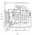
図1は、模式的に示された車両1に動力を供給するための過給燃焼機関用装置を示す。本実施例における燃焼機関は、ディーゼル機関2として例示されている。ディーゼル機関2は、大型車両1に動力を供給するために使用できる。ディーゼル機関2のシリンダから来る排気は、排気マニホルド3を経て排気ライン4に導入される。ディーゼル機関2は、タービン5および圧縮機6を含むターボ・ユニットを具備する。大気圧より高い排気ライン4の中の排気は、最初にタービン5に導入される。したがってタービン5は、接続を経て圧縮機6に伝達される駆動動力を有する。圧縮機6は、空気フィルタ7を経て空気入口ライン8に吸い込まれる空気を圧縮する。入口ライン8の中の空気は、最初に第1の冷媒冷却給気クーラー9内で冷却される。この空気は、燃焼機関の冷却系から来る冷媒によってこの第1給気クーラー9内で冷却される。次に、第2の冷媒冷却給気クーラー10で圧縮空気が冷却される。この空気は、第2冷却系から来る冷媒であって、燃焼機関の冷却系における冷媒の温度よりも低い冷媒によって、この第2給気クーラー10内で冷却される。 FIG. 1 shows an apparatus for a supercharged combustion engine for supplying power to a vehicle 1 schematically shown. The combustion engine in the present embodiment is exemplified as the
過給燃焼機関用装置は、排気ライン4の中の排気の一部の再循環を実施するための帰還ライン11を備えている。この帰還ライン11は、排気ライン4と入口ライン8の間に範囲を有している。帰還ライン11はEGR弁12を備えており、このEGR弁12によって、帰還ライン11の中の排気流を遮断することができる。また、このEGR弁12を使用して、排気ライン4から帰還ライン11を経て入口ライン8に導入される排気の量を連続的に制御することも可能である。第1制御ユニット13は、ディーゼル機関2の現在の運転状態に関する情報に基づいてEGR弁12を制御するようになされている。帰還ライン11は、排気に第1ステップの冷却を施すための第1の冷媒冷却EGRクーラー14を備えている。排気は、燃焼機関の冷却系から来る冷媒によってこの第1EGRクーラー14内で冷却される。この排気には、第2の冷媒冷却EGRクーラー15内で第2ステップの冷却が施される。排気は、第2冷却系から来る冷媒によってこの第2EGRクーラー15内で冷却される。 The supercharged combustion engine device includes a return line 11 for recirculating a part of the exhaust gas in the exhaust line 4. The return line 11 has a range between the exhaust line 4 and the inlet line 8. The return line 11 includes an EGR valve 12, and the exhaust flow in the return line 11 can be blocked by the EGR valve 12. It is also possible to continuously control the amount of exhaust gas introduced from the exhaust line 4 through the return line 11 to the inlet line 8 using the EGR valve 12. The
過給ディーゼル機関2の特定の運転状況では、排気ライン4の中の排気の圧力は、入口ライン8の中の圧縮空気の圧力より低くなる。このような運転状況では、特殊な補助手段なくしては、帰還ライン11の中の排気を入口ライン8の中の圧縮空気と直接混合することはできない。これらを直接混合するために、例えば、ベンチュリ16、つまり可変構造を有するターボ・ユニットを使用できる。燃焼機関2が過給ディーゼル機関ではなく、過給オットー機関である場合、オットー機関における排気ライン4中の排気圧力は、事実上全運転状態において、入口ライン8内の圧縮空気の圧力よりも高いため、帰還ライン11内の排気を直接入口ライン8に導入できる。排気が入口ライン8内の圧縮空気と混合されると、その混合物は、マニホルド17を経てディーゼル機関2の対応する個々のシリンダに導入される。 In certain operating situations of the
燃焼機関2は、循環する冷媒を含む冷却系によって従来の方法で冷却される。冷却系内の冷媒は、冷媒ポンプ18によって循環する。冷媒の主流は、燃焼機関2を通って循環し、燃焼機関2を冷却する。冷媒は、燃焼機関2を冷却した後、リターダーのためのオイルクーラー・エレメント28へのライン21に導入される。冷媒は、オイルクーラー・エレメント28内のオイルを冷却した後、ライン21を通ってサーモスタット19に導入される。サーモスタット19は、冷媒が通常の動作温度に到達すると、車両の前方部分に嵌合されたラジエータ20を冷却するために、該ラジエータ20に冷媒を導入するようになされている。ライン23は、冷却された冷媒を燃焼機関2に戻すように導いている。しかしながら、冷却系内の少量の冷媒は、燃焼機関2には戻されず、2本の平行のライン22a、22bに分かれているライン22を通って循環する。ライン22aは、圧縮空気に第1ステップの冷却を施す第1給気クーラー9に冷媒を導入している。ライン22bは、再循環排気に第1ステップの冷却を施す第1EGRクーラー14に冷媒を導入している。第1給気クーラー9内で空気を冷却した冷媒、および第1EGRクーラー14内で排気を冷却した冷媒は、サーモスタット19の上流側に配置されているライン21に冷媒を戻す前に、ライン22内で再結合される。次に、冷媒をラジエータ20または冷媒ポンプ18に導入することができる。 The
第2冷却系は、ラジエータ20の前方の、車両1の周辺領域に嵌合されたラジエータ・エレメント24を備えている。この場合、この周辺領域は、車両1の前方部分に位置している。ラジエータ・ファン25は、ラジエータ・エレメント24およびラジエータ20を経て周囲の空気の流れを生成するようになされている。ラジエータ・エレメント24はラジエータ20の前方に位置しているため、ラジエータ・エレメント24内の冷媒は、周囲温度の空気によって冷却される。したがってラジエータ・エレメント24の中の冷媒は、周囲温度に近い温度まで冷却することができる。ラジエータ・エレメント24から来る冷たい冷媒は、ライン系26内の第2冷却系の中をポンプ27によって循環する。第1接続ライン30は、燃焼機関の冷却系を第2冷却系に接続している。第1接続ライン30は、ライン21内の位置21aから第1三方弁32までの範囲を有している。燃焼機関の冷却系内の冷媒は、前記位置21aでその温度が最も高くなる。第1三方弁32は、第1接続ラインとライン系26のライン26dの間の接続領域に配置されている。第2三方弁34は、ライン系26の中に配置されている。第2三方弁34は、第2冷却系と燃焼機関の冷却系のライン23との間を延在している第2接続ライン33に接続されている。第2三方弁34は、ラジエータ24内で冷却された直後の冷たい冷媒を含有しているライン系26のライン26aの中に配置されている。ライン26aは、2本の平行ライン26b、26cに分かれている。ライン26bは、圧縮空気に第2ステップの冷却を施す第2給気クーラー10に冷たい冷媒を導入するようになされている。ライン26cは、再循環排気に第2ステップの冷却を施す第2EGRクーラー15に冷たい冷媒を導入するようになされている。冷媒が第2給気クーラー10および第2EGRクーラー15を通過すると、ライン26b、26cは、ラジエータ24に冷媒を導入しているライン26dに再結合される。第2制御ユニット31は、三方弁32、34を制御するようになされている。 The second cooling system includes a
ディーゼル機関2を運転している間、排気ライン4を通って排気が流れ、タービン5を駆動する。したがってタービン5は、圧縮機6を駆動する駆動動力を備えている。圧縮機6は、空気フィルタ7を経て周囲の空気を吸い込み、入口ライン8内で空気を圧縮する。したがって空気は、その圧力および温度が高くなる。圧縮空気は、第1給気クーラー9内で、燃焼機関の冷却系内のラジエータ液によって冷却される。このラジエータ液は、ここでは約80〜85℃の温度であってもよい。したがって、第1給気クーラー9内で、冷媒の温度に近い温度になるまで圧縮空気に第1ステップの冷却を施すことができる。制御ユニット31は、通常の運転中は、第2三方弁34の位置を、ライン26aから来る冷媒がライン26b、26cに導入される第1位置に維持するようになされている。ライン26bの中の冷たい冷媒によって、第2給気クーラー10内で圧縮空気が冷却される。この冷媒は、ここでは、周囲温度に近い温度であってもよい。したがって、第2給気クーラー10内で、有利な状況で、周囲温度に近い温度まで圧縮空気を冷却することができる。 While the
第1制御ユニット13は、ディーゼル機関2のほとんどの運転状態において、排気ライン4の中の排気の一部が帰還ライン11に導入されるよう、EGR弁12を開いた状態に維持する。排気ライン4の中の排気が第1EGRクーラー14に到達する際のそれらの温度は、約500〜600℃であってもよい。再循環排気には、第1EGRクーラー14内で、燃焼機関の冷却系内の冷媒によって第1ステップの冷却が施される。したがって燃焼機関の冷却系内の冷媒は比較的高い温度になるが、排気の温度より確実に低くなる。したがって第1EGRクーラー14内で良好に排気を冷却することができる。したがって制御ユニット31は、通常の運転中は、ライン26aから来る冷たい冷媒がライン26b、26cに導入されるよう、第2三方弁34の位置を第1位置に維持するようになされている。ライン26cの中の冷たい冷媒によって、第2EGRクーラー15内で再循環排気が冷却される。したがってこの冷媒は、ここでは、周囲温度に近い温度であってもよい。したがって、同様に、第2EGRクーラー15内で、有利な状況で、周囲温度に近い温度まで再循環排気を冷却することができる。したがって、混合され、かつ、燃焼機関2に導入される前の圧縮空気の温度と実質的に同じ低い温度まで、帰還ライン11の中の排気を冷却することができる。したがって実質的に最適の量の空気および再循環排気を燃焼機関に導入することができる。したがって、燃焼機関における実質的に最適の性能の燃焼を可能にすることができる。また、圧縮空気および再循環排気の温度が低いため、低い燃焼温度が得られ、また、排気中の窒素酸化物の含有量が少なくなる。 The
しかしながら、圧縮空気および再循環排気のこの有効な冷却には欠点もある。圧縮空気は、第2給気クーラー10内で、液体の形態の水が給気クーラー10内で凝縮する温度まで冷却される。同様に、第2EGRクーラー15の中の排気は、第2EGRクーラー15内に凝縮物が形成される温度まで冷却される。また、周囲の空気の温度が0℃未満である場合、第2給気クーラー10の中に析出した水、および第2EGRクーラー15の中に析出した凝縮物が凍結して氷になるリスクが存在する。第2給気クーラー10および第2EGRクーラー15内における氷の形成は、燃焼機関2の運転を著しく妨害することになる。第2制御ユニット31は、少なくとも1つのセンサから、第2給気クーラー10および/または第2EGRクーラー15の中に氷が形成されたかどうか、或いは氷が形成されるリスクが存在しているかどうかを示す情報を受け取るようになされている。図1には、第2冷却系内のライン26aの中の冷媒の温度を検出するこのようなセンサ35が示されている。ライン26aの中の冷媒の温度が0℃より確定的に低い場合、場合によっては第2給気クーラー10の中および/または第2EGRクーラー15の中に氷が形成されうる明らかなリスクが存在している。代替的には、制御ユニット31は、複数の温度センサから情報を受け取ることも可能である。1つのこのような温度センサは、第2給気クーラー10内で冷却された後の圧縮空気の温度を測定することができ、また、他の温度センサは、第2EGRクーラー15内で冷却された後の再循環排気の温度を測定することができる。圧縮空気および/または再循環排気の温度が0℃未満である場合、それは、給気クーラー10内および/または第2EGRクーラー15内に氷が形成されようとしていることを意味している。 However, this effective cooling of compressed air and recirculated exhaust also has drawbacks. The compressed air is cooled in the second air supply cooler 10 to a temperature at which water in liquid form condenses in the air supply cooler 10. Similarly, the exhaust in the second EGR cooler 15 is cooled to a temperature at which condensate is formed in the second EGR cooler 15. Further, when the temperature of the surrounding air is less than 0 ° C., there is a risk that the water deposited in the second air supply cooler 10 and the condensate deposited in the second EGR cooler 15 freeze and become ice. To do. The formation of ice in the second charge air cooler 10 and the second EGR cooler 15 significantly disturbs the operation of the
第2制御ユニット31は、クーラー10、15のいずれかの中に氷が形成されるリスクが存在しているか、或いは氷が形成されていることを示す情報を受け取ると、ポンプ27の運転を中断する。第2制御ユニット31は、燃焼機関の冷却系から来る暖かい冷媒が第1接続ライン30を経由して第2冷却系に導入されるよう、第1三方弁32を第2位置に位置づける。第2位置では、第1三方弁32は、第2冷却系内における通常の流れの方向とは逆の方向に暖かい冷媒を導く。したがって燃焼機関の冷却系から来る暖かい冷媒は、第2給気クーラー10および第2EGRクーラー15を通って逆方向に流れることになる。暖かい冷媒は、給気クーラー10および/または第2EGRクーラー15内に形成されたすべての氷を速やかに溶解させる。冷媒は、クーラー10、15を通過すると、ポンプ27を通り越して流れる。ポンプ27は、スイッチ・オフの状態では、冷媒が逆流方向にポンプ27を通って流れるように構成されている。また、第2制御ユニット31は、第2給気クーラー10および第2EGRクーラー15を通って逆方向に流れた冷媒が、第2接続ライン33を経て燃焼機関の冷却系に戻るように、第2三方弁34を第2位置に位置づける。所定の時間が経過するか、或いは給気クーラー10および/または第2EGRクーラー15内の氷が溶解していることを示す情報を第2制御ユニット31が受け取ると、第2制御ユニット31は、三方弁32、34をそれらの個々の第1位置に復帰させる。したがって給気クーラー10および/または第2EGRクーラー15内におけるあらゆる氷の形成を、単純で、かつ、効果的な方法で除去することができる。 When the
車両1は、この場合、オイル冷却リターダーを備えている。リターダー・オイルは、オイルクーラー・エレメント28内で、燃焼機関の冷却系内の冷媒によって冷却される。リターダーの制動能力は、通常、リターダーが起動されると生成される熱エネルギーを冷却系が冷却する能力によって制限されている。第2制御ユニット31は、リターダーが起動されると、情報を受け取るようになされている。この情報を受け取ると、第2制御ユニット31は、第2冷却系内のポンプ27をスイッチ・オフする。また、第2制御ユニットは、三方弁32、34を第3位置に位置づける。第1三方弁32が第3位置に置かれると、燃焼機関の冷却系から来る暖かい冷媒が第1接続ライン30を経由して第2冷却系に導入される。この場合、第1三方弁32は、第2冷却系内における通常の流れ方向に循環するように暖かい冷媒を導く。暖かい冷媒は、第1三方弁32からラジエータ・エレメント24に導入され、このラジエータ・エレメント24内で周囲温度の空気によって冷却される。この冷媒は、ライン26aを経由する第2三方弁34への導入に先立って、ラジエータ・エレメント24内で効果的に冷却される。したがって同じく第3位置に置かれている第2三方弁34は、冷媒を第1接続ライン33を経て燃焼機関の冷却系に戻す。 In this case, the vehicle 1 includes an oil cooling retarder. The retarder oil is cooled in the oil
第2制御ユニット31は、リターダーの起動が解除されていることを示す情報を受け取ると、三方弁32、34の位置をそれらの第1位置へ復帰させた後、第2冷却系内における冷媒の通常の循環が再開されるよう、ポンプ27を起動する。したがって、リターダーを起動している間、オイルクーラー28内でオイルを冷却した冷媒は、その一部が燃焼機関のラジエータ20に導入され、また、その一部が第2冷却系のラジエータ・エレメント24に導入される。これは、リターダーが起動されると、冷媒が極めて効果的に冷却されることを意味している。したがって、冷媒が最高許容温度に到達する前に、極めて長い時間にわたってリターダーを起動することが可能になる。したがってリターダーによる車両1の制動をより広範囲にわたって使用することができる。別法としては、リターダーが起動されると、制御ユニット31は、燃焼機関の冷却系内の冷媒が所定の温度より高くなっていることを示す情報を例えば温度センサから受け取るまでの間、それらの第3位置への三方弁32、34の配置を遅延させることも可能である。 When the
本発明は、図面に示されている実施例に何ら限定されず、特許請求の範囲の各請求項の範囲内で自由に変更することができる。この構造を使用して、前記クーラー10、15のうちの一方のみを実質的に氷が形成されない状態に維持することも可能である。図に示されている実施例では、リターダーの冷却が燃焼機関の冷却系にとって負担になる場合、弁手段32、34は、それらの第3位置に置かれる。しかしながら、車両の他のコンポーネントの冷却、或いは燃焼機関に対する極めて過酷な負荷も、場合によっては燃焼機関の冷却系内の冷媒が過熱する原因になることがある。このような状況の場合、燃焼機関の冷却系内の冷媒を冷却するために、同じく弁手段32、34をそれらの第3位置に位置づけることができる。 The present invention is not limited to the embodiments shown in the drawings, and can be freely changed within the scope of the claims. Using this structure, it is also possible to maintain only one of the coolers 10, 15 in a state where substantially no ice is formed. In the embodiment shown in the figure, when the retarder cooling is a burden on the combustion engine cooling system, the valve means 32, 34 are placed in their third position. However, cooling of other components of the vehicle, or extremely severe loads on the combustion engine can also cause overheating of the refrigerant in the combustion engine's cooling system. In such a situation, the valve means 32, 34 can likewise be positioned in their third position in order to cool the refrigerant in the cooling system of the combustion engine.
Claims (10)
Translated fromJapanese前記過給燃焼機関用装置が、前記第1冷却系を前記第2冷却系に接続する第1接続ライン(30)と、第1弁手段(32)とを含み、
該第1弁手段(32)は、前記第1冷却系から来る冷媒の、前記第1接続ライン(30)を経由する前記第2冷却系への導入を阻止する第1位置、および、前記第1冷却系から来る暖かい冷媒の前記第1接続ライン(30)を経由する前記第2冷却系への導入を許容する第2位置に位置づけることができ、
前記第1冷却系から来る前記暖かい冷媒が、前記クーラー(10、15)を通過するように、前記第2冷却系内で少なくとも所定距離(26b、26c)に亘って循環することが意図されていることを特徴とする過給燃焼機関用装置。An apparatus for a supercharged combustion engine (2), the apparatus comprising: a first cooling system having a circulating refrigerant; and the circulating refrigerant in the first cooling system during normal operation of the combustion engine (2). The supercharging comprising: a second cooling system having a circulating refrigerant lower than the temperature; and a cooler (10, 15) in which a gas medium containing water vapor is intended to be cooled by the circulating refrigerant of the second cooling system. In a combustion engine device,
The supercharged combustion engine device includes a first connection line (30) for connecting the first cooling system to the second cooling system, and first valve means (32),
The first valve means (32) has a first position for preventing the refrigerant coming from the first cooling system from being introduced into the second cooling system via the first connection line (30); and Can be positioned in a second position allowing the introduction of warm refrigerant coming from one cooling system into the second cooling system via the first connection line (30),
It is intended that the warm refrigerant coming from the first cooling system circulates at least a predetermined distance (26b, 26c) in the second cooling system so as to pass through the cooler (10, 15). A supercharged combustion engine device.
前記第2接続ライン(33)は、前記第1冷却系を前記第2冷却系に接続し、
前記第2弁手段(34)は、前記第2冷却系から来る冷媒の前記第2接続ライン(33)を経由する前記第1冷却系への導入を阻止する第1位置、および、前記クーラー(10、15)を通過した前記冷媒の前記第2接続ライン(33)を経由する前記第1冷却系への戻りを許容する第2位置に位置づけることができるようになされていることを特徴とする請求項1に記載された過給燃焼機関用装置。The supercharged combustion engine device includes a second connection line (33) and second valve means (34),
The second connection line (33) connects the first cooling system to the second cooling system,
The second valve means (34) includes a first position for preventing introduction of the refrigerant coming from the second cooling system into the first cooling system via the second connection line (33), and the cooler ( 10, 15), the refrigerant passing through the second connection line (33) can be positioned at a second position that allows the refrigerant to return to the first cooling system. The supercharged combustion engine device according to claim 1.
前記制御ユニット(31)は、前記個々の弁手段(32、34)を制御するようになされ、
前記少なくとも1つのセンサ(35)は、前記クーラー(10、15)内に氷が形成されるか、または、氷が形成されるリスクが存在する程度まで前記ガス媒体が冷却されているか否かを示すパラメータを検出するようになされており、
前記制御ユニット(31)は、前記センサ(35)から情報を受け取って、前記クーラー(10、15)内に氷が形成されているか、または、氷が形成されるリスクが存在しているか否かを判定し、判定結果が肯定的である場合には、前記第1弁手段(32)および前記第2弁手段(34)をそれらの個々の第2位置に位置づけるように構成されていることを特徴とする請求項1および請求項2に記載された過給燃焼機関用装置。The supercharged combustion engine device includes a control unit (31) and at least one sensor (35),
The control unit (31) is adapted to control the individual valve means (32, 34),
The at least one sensor (35) determines whether the gas medium is cooled to the extent that ice is formed in the coolers (10, 15) or there is a risk of ice formation. It is designed to detect the parameters shown,
The control unit (31) receives information from the sensor (35) and whether ice is formed in the coolers (10, 15) or whether there is a risk of ice formation. If the determination result is affirmative, the first valve means (32) and the second valve means (34) are configured to be positioned in their respective second positions. The supercharged combustion engine device according to claim 1 or 2, characterized in that it is characterized in that:
Applications Claiming Priority (3)
| Application Number | Priority Date | Filing Date | Title |
|---|---|---|---|
| SE0800899-7 | 2008-04-18 | ||
| SE0800899ASE532245C2 (en) | 2008-04-18 | 2008-04-18 | Cooling arrangement of a supercharged internal combustion engine |
| PCT/SE2009/050207WO2009128768A1 (en) | 2008-04-18 | 2009-02-25 | Cooling arrangement for a supercharged internal combustion engine |
Publications (2)
| Publication Number | Publication Date |
|---|---|
| JP2011518279Atrue JP2011518279A (en) | 2011-06-23 |
| JP5198653B2 JP5198653B2 (en) | 2013-05-15 |
Family
ID=41199328
Family Applications (1)
| Application Number | Title | Priority Date | Filing Date |
|---|---|---|---|
| JP2011504959AExpired - Fee RelatedJP5198653B2 (en) | 2008-04-18 | 2009-02-25 | Cooling device for supercharged internal combustion engine |
Country Status (6)
| Country | Link |
|---|---|
| US (1) | US8424303B2 (en) |
| EP (1) | EP2286068B1 (en) |
| JP (1) | JP5198653B2 (en) |
| CN (1) | CN102007280B (en) |
| SE (1) | SE532245C2 (en) |
| WO (1) | WO2009128768A1 (en) |
Cited By (5)
| Publication number | Priority date | Publication date | Assignee | Title |
|---|---|---|---|---|
| JP2012207549A (en)* | 2011-03-29 | 2012-10-25 | Hino Motors Ltd | Egr device |
| WO2013039176A1 (en)* | 2011-09-16 | 2013-03-21 | カルソニックカンセイ株式会社 | Egr gas cooling system |
| WO2014132755A1 (en)* | 2013-02-27 | 2014-09-04 | カルソニックカンセイ株式会社 | Cooling device and cooling method for exhaust recirculation device |
| WO2015102037A1 (en)* | 2014-01-06 | 2015-07-09 | 株式会社デンソー | Intake air cooling device |
| KR20190041743A (en)* | 2017-10-13 | 2019-04-23 | 현대자동차주식회사 | System and Method for cooling engine of vehicle |
Families Citing this family (35)
| Publication number | Priority date | Publication date | Assignee | Title |
|---|---|---|---|---|
| SE533750C2 (en)* | 2008-06-09 | 2010-12-21 | Scania Cv Ab | Arrangement of a supercharged internal combustion engine |
| SE534270C2 (en)* | 2008-11-05 | 2011-06-21 | Scania Cv Ab | Arrangement for cooling of recirculating exhaust gases of an internal combustion engine |
| JP5322911B2 (en)* | 2009-12-24 | 2013-10-23 | 日野自動車株式会社 | Engine exhaust gas purification device |
| US8602007B2 (en)* | 2010-09-17 | 2013-12-10 | GM Global Technology Operations LLC | Integrated exhaust gas recirculation and charge cooling system |
| SE535564C2 (en)* | 2010-12-22 | 2012-09-25 | Scania Cv Ab | Cooling system in a vehicle |
| US8813489B2 (en)* | 2011-02-15 | 2014-08-26 | Deere & Company | Internal combustion engine charge air cooler precooler |
| DE102011076457A1 (en)* | 2011-05-25 | 2012-11-29 | Ford Global Technologies, Llc | Cooling arrangement for a rechargeable internal combustion engine |
| JP2013113182A (en)* | 2011-11-28 | 2013-06-10 | Calsonic Kansei Corp | Cooling apparatus for engine and cooling method thereof |
| JP2013256936A (en)* | 2012-05-16 | 2013-12-26 | Denso Corp | Exhaust recirculating device |
| US20140034027A1 (en)* | 2012-07-31 | 2014-02-06 | Caterpillar Inc. | Exhaust gas re-circulation system |
| US9650942B2 (en)* | 2012-10-19 | 2017-05-16 | Ford Global Technologies, Llc | Engine control coordination with grille shutter adjustment and ambient conditions |
| CN103863271B (en)* | 2012-12-12 | 2016-11-23 | 北汽福田汽车股份有限公司 | The cooling system of vehicle |
| JP5962534B2 (en)* | 2013-02-15 | 2016-08-03 | トヨタ自動車株式会社 | Intercooler temperature controller |
| FR3002285B1 (en)* | 2013-02-20 | 2015-02-20 | Renault Sa | EXHAUST GAS HEAT RECOVERY SYSTEM IN AN INTERNAL COMBUSTION ENGINE, WITH TWO HEAT EXCHANGERS AT A GAS RECIRCULATION CIRCUIT |
| DE102013215608A1 (en)* | 2013-08-07 | 2015-02-12 | Behr Gmbh & Co. Kg | Cooling system and associated operating method |
| FR3014138B1 (en)* | 2013-12-02 | 2016-01-01 | Renault Sas | VEHICLE COMPRISING A COOLING CIRCUIT EQUIPPED WITH A THERMAL EXCHANGER WITH AN EXHAUST GAS RECIRCULATION TUBE AND CONTROL MEANS FOR HEATING THE FLUID HEAT PUMP |
| KR101534725B1 (en)* | 2013-12-06 | 2015-07-07 | 현대자동차 주식회사 | Engine system having turbo charger |
| KR101490963B1 (en)* | 2013-12-11 | 2015-02-06 | 현대자동차 주식회사 | Engine system having turbo charger |
| KR101601088B1 (en)* | 2013-12-23 | 2016-03-09 | 현대자동차주식회사 | Engine Cooling System |
| JP5904227B2 (en)* | 2014-03-24 | 2016-04-13 | トヨタ自動車株式会社 | Engine cooling system |
| GB2526815A (en) | 2014-06-03 | 2015-12-09 | Gm Global Tech Operations Inc | A cooling system for an internal combustion engine |
| US9670823B2 (en)* | 2015-03-24 | 2017-06-06 | GM Global Technology Operations LLC | Engine with a turbocharger cooling module |
| US10030575B2 (en)* | 2015-07-09 | 2018-07-24 | Ford Global Technologies, Llc | System and method for flowing a mixture of coolants to a charge air cooler |
| TR201509225A2 (en)* | 2015-07-27 | 2017-02-21 | Ford Otomotiv Sanayi As | EGR COOLING SYSTEM AND METHOD |
| GB2546732A (en)* | 2016-01-21 | 2017-08-02 | Gm Global Tech Operations Llc | A turbocharged automotive system |
| SE542204C2 (en)* | 2016-06-09 | 2020-03-10 | Scania Cv Ab | A cooling system for an electric power unit in a vehicle |
| EP3385524B1 (en)* | 2017-04-03 | 2019-07-17 | Denso Corporation | System for controlling an intake temperature of charge air |
| US10920656B2 (en)* | 2017-06-09 | 2021-02-16 | Pratt & Whitney Canada Corp. | Internal combustion engine cooling system |
| JP7010724B2 (en)* | 2018-02-19 | 2022-01-26 | トヨタ自動車株式会社 | Vehicle cooling system |
| FR3080443B1 (en)* | 2018-04-18 | 2020-06-19 | Renault S.A.S. | COOLING RADIATOR WITH INTEGRATED BY-PASS AND COOLING CIRCUIT |
| WO2020038575A1 (en) | 2018-08-23 | 2020-02-27 | Volvo Truck Corporation | A method for operating an internal combustion engine system |
| CN112585341B (en) | 2018-08-23 | 2024-01-05 | 沃尔沃卡车集团 | Method for controlling an internal combustion engine system |
| US12117213B1 (en) | 2018-11-19 | 2024-10-15 | Justin Schaefer | Portable internal combustion engine with heating and cooling capabilities |
| CN111206981A (en)* | 2018-11-21 | 2020-05-29 | 福特全球技术公司 | Control valve for a cooling radiator arrangement |
| CN117043460A (en)* | 2020-12-16 | 2023-11-10 | 电控装置有限责任公司 | Low pressure EGR system with condensate management |
Citations (16)
| Publication number | Priority date | Publication date | Assignee | Title |
|---|---|---|---|---|
| DE1128702B (en)* | 1959-03-26 | 1962-04-26 | Sueddeutsche Kuehler Behr | Liquid cooling system for internal combustion engines with charging |
| GB950020A (en)* | 1961-12-18 | 1964-02-19 | Manfred Behr | Improvements relating to supercharged internal combustion engine cooling arrangements |
| JPS59138717A (en)* | 1983-01-28 | 1984-08-09 | Toyota Motor Corp | Cooling device of internal-combustion engine with turbo- charger equipped with water-cooling type inter-cooler |
| US5910099A (en)* | 1997-02-28 | 1999-06-08 | General Motors Corporation | Turbocharged engine cooling system control with fuel economy optimization |
| JP2001140704A (en)* | 1999-10-07 | 2001-05-22 | Cummins Engine Co Inc | High temperature cooling agent loop for recirculating cooling exhaust gas for internal combustion engine |
| US20050000473A1 (en)* | 2001-11-13 | 2005-01-06 | Ap Ngy Srun | System for managing the heat energy produced by a motor vehicle heat engine |
| US20060117748A1 (en)* | 2003-04-11 | 2006-06-08 | Steffen Bundschuh | Circuit arrangement which cools charging air and method for the operation of said type of circuit arrangement |
| US20060213463A1 (en)* | 2003-03-28 | 2006-09-28 | Hans Wikstrom | Cooling arrangement and a method for cooling retarder |
| WO2007122345A1 (en)* | 2006-04-21 | 2007-11-01 | Renault S.A.S | System and method for controlling the temperature of a supercharged engine comprising an exhaust gas recycling circuit |
| WO2008007561A1 (en)* | 2006-07-10 | 2008-01-17 | Calsonic Kansei Corporation | Egr device |
| WO2008080872A1 (en)* | 2006-12-29 | 2008-07-10 | Valeo Systemes Thermiques | High/low temperature water cooling system and a four port valve for such a system |
| JP2009507717A (en)* | 2005-09-13 | 2009-02-26 | ルノー・エス・アー・エス | Method for controlling vehicle drive train with two cooling circuits |
| JP2009509097A (en)* | 2005-09-20 | 2009-03-05 | スカニア シーブイ アクチボラグ(パブル) | Device for recirculation of exhaust gas from a supercharged internal combustion engine |
| JP2009535553A (en)* | 2006-04-28 | 2009-10-01 | スカニア シーブイ アクチボラグ | Vehicle cooling fan device |
| JP2010505692A (en)* | 2006-10-03 | 2010-02-25 | スカニア シーブイ アクチボラグ | Vehicle cooling device |
| JP2011523691A (en)* | 2008-06-09 | 2011-08-18 | スカニア シーブイ アクチボラグ | Equipment for supercharged combustion engines |
Family Cites Families (13)
| Publication number | Priority date | Publication date | Assignee | Title |
|---|---|---|---|---|
| US6564757B2 (en)* | 2000-06-22 | 2003-05-20 | Toyota Jidosha Kabushiki Kaisha | Internal combustion engine including heat accumulation system, and heat carrier supply control system |
| US6604515B2 (en)* | 2001-06-20 | 2003-08-12 | General Electric Company | Temperature control for turbocharged engine |
| DE10134678A1 (en)* | 2001-07-20 | 2003-02-06 | Bosch Gmbh Robert | Arrangement for cooling and heating motor vehicle, has at least one bypass line with bypass valve associated with and arranged in parallel with at least one auxiliary radiator segment |
| FR2835884B1 (en)* | 2002-02-12 | 2005-03-18 | Valeo Thermique Moteur Sa | METHOD FOR CONTROLLING THE GAS TEMPERATURE ADMITTED IN A MOTOR VEHICLE ENGINE, EXCHANGER AND DEVICE FOR MANAGING THE TEMPERATURE OF THESE GASES |
| DE10319762A1 (en)* | 2003-04-30 | 2004-12-02 | Behr Gmbh & Co. Kg | Charge air cooling circuit and method of operating such a circuit |
| SE527479C2 (en)* | 2004-05-28 | 2006-03-21 | Scania Cv Ab | Arrangements for the recirculation of exhaust gases of a supercharged internal combustion engine |
| SE528621C2 (en)* | 2005-05-18 | 2006-12-27 | Scania Cv Ab | Arrangements for the recirculation of exhaust gases of a supercharged internal combustion engine |
| FR2892155B1 (en)* | 2005-10-19 | 2007-12-14 | Inst Francais Du Petrole | CIRCUIT FOR SUPPLYING AT LEAST ONE FLUID OF A SUPERCHARGED MOTOR AND METHOD FOR FEEDING AT AT LEAST ONE FLUID SUCH A MOTOR |
| JP2009515088A (en)* | 2005-11-10 | 2009-04-09 | ベール ゲーエムベーハー ウント コー カーゲー | Circuit system, mixer |
| US7448212B2 (en)* | 2006-02-27 | 2008-11-11 | International Engine Intellectual Property Company, Llc | Engine bleed air passage and method |
| DE102006044820B4 (en)* | 2006-09-20 | 2019-03-07 | MAN Truck & Bus Österreich AG | Cooling system of an internal combustion engine with charge air supply |
| DE102008028290B4 (en)* | 2008-06-16 | 2019-05-16 | Mahle International Gmbh | Means for cooling a coolant, a circuit for charging an internal combustion engine and method for cooling an intended for charging an internal combustion engine substantially gaseous charging fluid |
| US8215381B2 (en)* | 2009-04-10 | 2012-07-10 | Ford Global Technologies, Llc | Method for controlling heat exchanger fluid flow |
- 2008
- 2008-04-18SESE0800899Apatent/SE532245C2/ennot_activeIP Right Cessation
- 2009
- 2009-02-25USUS12/936,529patent/US8424303B2/ennot_activeExpired - Fee Related
- 2009-02-25WOPCT/SE2009/050207patent/WO2009128768A1/enactiveApplication Filing
- 2009-02-25CNCN2009801136858Apatent/CN102007280B/ennot_activeExpired - Fee Related
- 2009-02-25JPJP2011504959Apatent/JP5198653B2/ennot_activeExpired - Fee Related
- 2009-02-25EPEP09732695.3Apatent/EP2286068B1/ennot_activeNot-in-force
Patent Citations (16)
| Publication number | Priority date | Publication date | Assignee | Title |
|---|---|---|---|---|
| DE1128702B (en)* | 1959-03-26 | 1962-04-26 | Sueddeutsche Kuehler Behr | Liquid cooling system for internal combustion engines with charging |
| GB950020A (en)* | 1961-12-18 | 1964-02-19 | Manfred Behr | Improvements relating to supercharged internal combustion engine cooling arrangements |
| JPS59138717A (en)* | 1983-01-28 | 1984-08-09 | Toyota Motor Corp | Cooling device of internal-combustion engine with turbo- charger equipped with water-cooling type inter-cooler |
| US5910099A (en)* | 1997-02-28 | 1999-06-08 | General Motors Corporation | Turbocharged engine cooling system control with fuel economy optimization |
| JP2001140704A (en)* | 1999-10-07 | 2001-05-22 | Cummins Engine Co Inc | High temperature cooling agent loop for recirculating cooling exhaust gas for internal combustion engine |
| US20050000473A1 (en)* | 2001-11-13 | 2005-01-06 | Ap Ngy Srun | System for managing the heat energy produced by a motor vehicle heat engine |
| US20060213463A1 (en)* | 2003-03-28 | 2006-09-28 | Hans Wikstrom | Cooling arrangement and a method for cooling retarder |
| US20060117748A1 (en)* | 2003-04-11 | 2006-06-08 | Steffen Bundschuh | Circuit arrangement which cools charging air and method for the operation of said type of circuit arrangement |
| JP2009507717A (en)* | 2005-09-13 | 2009-02-26 | ルノー・エス・アー・エス | Method for controlling vehicle drive train with two cooling circuits |
| JP2009509097A (en)* | 2005-09-20 | 2009-03-05 | スカニア シーブイ アクチボラグ(パブル) | Device for recirculation of exhaust gas from a supercharged internal combustion engine |
| WO2007122345A1 (en)* | 2006-04-21 | 2007-11-01 | Renault S.A.S | System and method for controlling the temperature of a supercharged engine comprising an exhaust gas recycling circuit |
| JP2009535553A (en)* | 2006-04-28 | 2009-10-01 | スカニア シーブイ アクチボラグ | Vehicle cooling fan device |
| WO2008007561A1 (en)* | 2006-07-10 | 2008-01-17 | Calsonic Kansei Corporation | Egr device |
| JP2010505692A (en)* | 2006-10-03 | 2010-02-25 | スカニア シーブイ アクチボラグ | Vehicle cooling device |
| WO2008080872A1 (en)* | 2006-12-29 | 2008-07-10 | Valeo Systemes Thermiques | High/low temperature water cooling system and a four port valve for such a system |
| JP2011523691A (en)* | 2008-06-09 | 2011-08-18 | スカニア シーブイ アクチボラグ | Equipment for supercharged combustion engines |
Cited By (8)
| Publication number | Priority date | Publication date | Assignee | Title |
|---|---|---|---|---|
| JP2012207549A (en)* | 2011-03-29 | 2012-10-25 | Hino Motors Ltd | Egr device |
| WO2013039176A1 (en)* | 2011-09-16 | 2013-03-21 | カルソニックカンセイ株式会社 | Egr gas cooling system |
| WO2014132755A1 (en)* | 2013-02-27 | 2014-09-04 | カルソニックカンセイ株式会社 | Cooling device and cooling method for exhaust recirculation device |
| JP2014163335A (en)* | 2013-02-27 | 2014-09-08 | Calsonic Kansei Corp | Cooling device of exhaust gas recirculation device |
| WO2015102037A1 (en)* | 2014-01-06 | 2015-07-09 | 株式会社デンソー | Intake air cooling device |
| JP2015145667A (en)* | 2014-01-06 | 2015-08-13 | 株式会社デンソー | Intake air cooling device |
| KR20190041743A (en)* | 2017-10-13 | 2019-04-23 | 현대자동차주식회사 | System and Method for cooling engine of vehicle |
| KR102371612B1 (en) | 2017-10-13 | 2022-03-07 | 현대자동차주식회사 | System and Method for cooling engine of vehicle |
Also Published As
| Publication number | Publication date |
|---|---|
| SE532245C2 (en) | 2009-11-24 |
| CN102007280A (en) | 2011-04-06 |
| US20110041814A1 (en) | 2011-02-24 |
| EP2286068A1 (en) | 2011-02-23 |
| EP2286068A4 (en) | 2013-10-30 |
| SE0800899L (en) | 2009-10-19 |
| WO2009128768A1 (en) | 2009-10-22 |
| US8424303B2 (en) | 2013-04-23 |
| CN102007280B (en) | 2013-04-17 |
| JP5198653B2 (en) | 2013-05-15 |
| EP2286068B1 (en) | 2015-07-29 |
Similar Documents
| Publication | Publication Date | Title |
|---|---|---|
| JP5198653B2 (en) | Cooling device for supercharged internal combustion engine | |
| KR101531360B1 (en) | Arrangement at a supercharged internal combustion engine | |
| JP5068389B2 (en) | Cooling device for supercharged combustion engine | |
| JP4739453B2 (en) | Exhaust gas circulation system for supercharged combustion engine | |
| US7299771B2 (en) | Coolant valve system for internal combustion engine and method | |
| US7650753B2 (en) | Arrangement for cooling exhaust gas and charge air | |
| JP5522874B2 (en) | Vehicle cooling system | |
| RU2449136C1 (en) | Device for internal combustion engine with supercharge | |
| KR101343559B1 (en) | Cooling arrangement in a vehicle | |
| JP5172017B2 (en) | Apparatus in a cryogenic cooling system for a supercharged internal combustion engine | |
| JP2010511125A (en) | Vehicle cooler device | |
| CN110857652A (en) | Cooling system for internal combustion engine | |
| EP2757245A1 (en) | Egr gas cooling system | |
| KR20190040454A (en) | Method for operating an internal combustion engine, internal combustion engine and motor vehicle |
Legal Events
| Date | Code | Title | Description |
|---|---|---|---|
| A131 | Notification of reasons for refusal | Free format text:JAPANESE INTERMEDIATE CODE: A131 Effective date:20120403 | |
| A521 | Request for written amendment filed | Free format text:JAPANESE INTERMEDIATE CODE: A523 Effective date:20120703 | |
| TRDD | Decision of grant or rejection written | ||
| A01 | Written decision to grant a patent or to grant a registration (utility model) | Free format text:JAPANESE INTERMEDIATE CODE: A01 Effective date:20130201 | |
| A61 | First payment of annual fees (during grant procedure) | Free format text:JAPANESE INTERMEDIATE CODE: A61 Effective date:20130206 | |
| FPAY | Renewal fee payment (event date is renewal date of database) | Free format text:PAYMENT UNTIL: 20160215 Year of fee payment:3 | |
| R150 | Certificate of patent or registration of utility model | Free format text:JAPANESE INTERMEDIATE CODE: R150 | |
| LAPS | Cancellation because of no payment of annual fees |