JP2011517977A - Device and method for reducing stomach - Google Patents
Device and method for reducing stomachDownload PDFInfo
- Publication number
- JP2011517977A JP2011517977AJP2011504159AJP2011504159AJP2011517977AJP 2011517977 AJP2011517977 AJP 2011517977AJP 2011504159 AJP2011504159 AJP 2011504159AJP 2011504159 AJP2011504159 AJP 2011504159AJP 2011517977 AJP2011517977 AJP 2011517977A
- Authority
- JP
- Japan
- Prior art keywords
- suture
- stomach
- tissue
- vacuum
- column
- Prior art date
- Legal status (The legal status is an assumption and is not a legal conclusion. Google has not performed a legal analysis and makes no representation as to the accuracy of the status listed.)
- Pending
Links
- 210000002784stomachAnatomy0.000titleclaimsabstractdescription126
- 238000000034methodMethods0.000titleclaimsabstractdescription53
- 230000002496gastric effectEffects0.000claimsabstractdescription130
- 210000003238esophagusAnatomy0.000claimsdescription10
- 230000035515penetrationEffects0.000claimsdescription9
- 230000008569processEffects0.000claimsdescription3
- 230000000149penetrating effectEffects0.000claims3
- 238000004873anchoringMethods0.000abstract1
- 230000009467reductionEffects0.000description103
- 210000001519tissueAnatomy0.000description87
- 239000000463materialSubstances0.000description34
- 230000008878couplingEffects0.000description26
- 238000010168coupling processMethods0.000description26
- 238000005859coupling reactionMethods0.000description26
- 210000000214mouthAnatomy0.000description10
- 238000003780insertionMethods0.000description9
- 230000037431insertionEffects0.000description9
- 239000004033plasticSubstances0.000description8
- 229920003023plasticPolymers0.000description8
- 238000001356surgical procedureMethods0.000description7
- 238000004804windingMethods0.000description7
- 239000012530fluidSubstances0.000description6
- 229910001220stainless steelInorganic materials0.000description6
- 239000010935stainless steelSubstances0.000description6
- 230000002829reductive effectEffects0.000description5
- 230000008901benefitEffects0.000description4
- 210000003205muscleAnatomy0.000description4
- 229910001000nickel titaniumInorganic materials0.000description4
- 210000000056organAnatomy0.000description4
- 229920001343polytetrafluoroethylenePolymers0.000description4
- 206010025476MalabsorptionDiseases0.000description3
- 208000004155Malabsorption SyndromesDiseases0.000description3
- 208000008589ObesityDiseases0.000description3
- 210000003414extremityAnatomy0.000description3
- 208000015181infectious diseaseDiseases0.000description3
- 229910052751metalInorganic materials0.000description3
- 239000002184metalSubstances0.000description3
- HLXZNVUGXRDIFK-UHFFFAOYSA-Nnickel titaniumChemical compound[Ti].[Ti].[Ti].[Ti].[Ti].[Ti].[Ti].[Ti].[Ti].[Ti].[Ti].[Ni].[Ni].[Ni].[Ni].[Ni].[Ni].[Ni].[Ni].[Ni].[Ni].[Ni].[Ni].[Ni].[Ni]HLXZNVUGXRDIFK-UHFFFAOYSA-N0.000description3
- 235000020824obesityNutrition0.000description3
- -1polypropylenePolymers0.000description3
- 230000004580weight lossEffects0.000description3
- 206010019909HerniaDiseases0.000description2
- XUIMIQQOPSSXEZ-UHFFFAOYSA-NSiliconChemical compound[Si]XUIMIQQOPSSXEZ-UHFFFAOYSA-N0.000description2
- 229920000122acrylonitrile butadiene styrenePolymers0.000description2
- 239000004676acrylonitrile butadiene styreneSubstances0.000description2
- 239000000853adhesiveSubstances0.000description2
- 230000001070adhesive effectEffects0.000description2
- 230000008859changeEffects0.000description2
- 230000008602contractionEffects0.000description2
- 238000002474experimental methodMethods0.000description2
- 238000000605extractionMethods0.000description2
- 230000006870functionEffects0.000description2
- 238000009434installationMethods0.000description2
- 239000007769metal materialSubstances0.000description2
- 238000012986modificationMethods0.000description2
- 230000004048modificationEffects0.000description2
- 230000036961partial effectEffects0.000description2
- 239000000088plastic resinSubstances0.000description2
- 238000011084recoveryMethods0.000description2
- 238000000926separation methodMethods0.000description2
- 229910052710siliconInorganic materials0.000description2
- 239000010703siliconSubstances0.000description2
- 238000010561standard procedureMethods0.000description2
- 239000000126substanceSubstances0.000description2
- 230000007704transitionEffects0.000description2
- 210000001835visceraAnatomy0.000description2
- 206010050456Anastomotic leakDiseases0.000description1
- 229920004943Delrin®Polymers0.000description1
- 206010012335DependenceDiseases0.000description1
- 208000032843HemorrhageDiseases0.000description1
- 239000004677NylonSubstances0.000description1
- 239000004743PolypropyleneSubstances0.000description1
- 208000010378Pulmonary EmbolismDiseases0.000description1
- 206010039897SedationDiseases0.000description1
- FAPWRFPIFSIZLT-UHFFFAOYSA-MSodium chlorideChemical compound[Na+].[Cl-]FAPWRFPIFSIZLT-UHFFFAOYSA-M0.000description1
- 208000025865UlcerDiseases0.000description1
- 208000027418Wounds and injuryDiseases0.000description1
- HZEWFHLRYVTOIW-UHFFFAOYSA-N[Ti].[Ni]Chemical compound[Ti].[Ni]HZEWFHLRYVTOIW-UHFFFAOYSA-N0.000description1
- 229910052782aluminiumInorganic materials0.000description1
- XAGFODPZIPBFFR-UHFFFAOYSA-NaluminiumChemical compound[Al]XAGFODPZIPBFFR-UHFFFAOYSA-N0.000description1
- 230000000845anti-microbial effectEffects0.000description1
- 239000004599antimicrobialSubstances0.000description1
- 238000013459approachMethods0.000description1
- 238000007681bariatric surgeryMethods0.000description1
- 230000015572biosynthetic processEffects0.000description1
- 208000034158bleedingDiseases0.000description1
- 230000000740bleeding effectEffects0.000description1
- 230000015556catabolic processEffects0.000description1
- 238000005336crackingMethods0.000description1
- 230000003247decreasing effectEffects0.000description1
- 238000006731degradation reactionMethods0.000description1
- 235000021045dietary changeNutrition0.000description1
- 230000029087digestionEffects0.000description1
- 102000038379digestive enzymesHuman genes0.000description1
- 108091007734digestive enzymesProteins0.000description1
- 238000011038discontinuous diafiltration by volume reductionMethods0.000description1
- 238000006073displacement reactionMethods0.000description1
- 238000001839endoscopyMethods0.000description1
- 230000003628erosive effectEffects0.000description1
- 238000002594fluoroscopyMethods0.000description1
- 230000000774hypoallergenic effectEffects0.000description1
- 239000007943implantSubstances0.000description1
- 208000014674injuryDiseases0.000description1
- 230000002452interceptive effectEffects0.000description1
- 238000002955isolationMethods0.000description1
- 210000001630jejunumAnatomy0.000description1
- 210000002429large intestineAnatomy0.000description1
- 230000000670limiting effectEffects0.000description1
- 230000014759maintenance of locationEffects0.000description1
- 230000013011matingEffects0.000description1
- 230000007246mechanismEffects0.000description1
- 230000003387muscularEffects0.000description1
- 231100000252nontoxicToxicity0.000description1
- 230000003000nontoxic effectEffects0.000description1
- 229920001778nylonPolymers0.000description1
- 238000005192partitionMethods0.000description1
- 239000004417polycarbonateSubstances0.000description1
- 229920000515polycarbonatePolymers0.000description1
- 229920000728polyesterPolymers0.000description1
- 229920001155polypropylenePolymers0.000description1
- 229920002635polyurethanePolymers0.000description1
- 239000004814polyurethaneSubstances0.000description1
- 235000003784poor nutritionNutrition0.000description1
- 238000002360preparation methodMethods0.000description1
- 238000001671psychotherapyMethods0.000description1
- 239000011347resinSubstances0.000description1
- 229920005989resinPolymers0.000description1
- 230000000717retained effectEffects0.000description1
- 238000012552reviewMethods0.000description1
- 230000036280sedationEffects0.000description1
- 210000000813small intestineAnatomy0.000description1
- 239000011780sodium chlorideSubstances0.000description1
- 210000000952spleenAnatomy0.000description1
- 238000007920subcutaneous administrationMethods0.000description1
- 238000006467substitution reactionMethods0.000description1
- 230000009026tissue transitionEffects0.000description1
- 210000003371toeAnatomy0.000description1
- 238000012546transferMethods0.000description1
- 230000008733traumaEffects0.000description1
- 231100000397ulcerToxicity0.000description1
- 230000000007visual effectEffects0.000description1
Images


Classifications
- A—HUMAN NECESSITIES
- A61—MEDICAL OR VETERINARY SCIENCE; HYGIENE
- A61B—DIAGNOSIS; SURGERY; IDENTIFICATION
- A61B17/00—Surgical instruments, devices or methods
- A61B17/04—Surgical instruments, devices or methods for suturing wounds; Holders or packages for needles or suture materials
- A61B17/0469—Suturing instruments for use in minimally invasive surgery, e.g. endoscopic surgery
- A—HUMAN NECESSITIES
- A61—MEDICAL OR VETERINARY SCIENCE; HYGIENE
- A61F—FILTERS IMPLANTABLE INTO BLOOD VESSELS; PROSTHESES; DEVICES PROVIDING PATENCY TO, OR PREVENTING COLLAPSING OF, TUBULAR STRUCTURES OF THE BODY, e.g. STENTS; ORTHOPAEDIC, NURSING OR CONTRACEPTIVE DEVICES; FOMENTATION; TREATMENT OR PROTECTION OF EYES OR EARS; BANDAGES, DRESSINGS OR ABSORBENT PADS; FIRST-AID KITS
- A61F5/00—Orthopaedic methods or devices for non-surgical treatment of bones or joints; Nursing devices ; Anti-rape devices
- A61F5/0003—Apparatus for the treatment of obesity; Anti-eating devices
- A61F5/0013—Implantable devices or invasive measures
- A61F5/0083—Reducing the size of the stomach, e.g. gastroplasty
- A61F5/0086—Reducing the size of the stomach, e.g. gastroplasty using clamps, folding means or the like
- A—HUMAN NECESSITIES
- A61—MEDICAL OR VETERINARY SCIENCE; HYGIENE
- A61B—DIAGNOSIS; SURGERY; IDENTIFICATION
- A61B17/00—Surgical instruments, devices or methods
- A61B17/04—Surgical instruments, devices or methods for suturing wounds; Holders or packages for needles or suture materials
- A61B17/0482—Needle or suture guides
- A—HUMAN NECESSITIES
- A61—MEDICAL OR VETERINARY SCIENCE; HYGIENE
- A61B—DIAGNOSIS; SURGERY; IDENTIFICATION
- A61B17/00—Surgical instruments, devices or methods
- A61B2017/00743—Type of operation; Specification of treatment sites
- A61B2017/00818—Treatment of the gastro-intestinal system
- A—HUMAN NECESSITIES
- A61—MEDICAL OR VETERINARY SCIENCE; HYGIENE
- A61B—DIAGNOSIS; SURGERY; IDENTIFICATION
- A61B17/00—Surgical instruments, devices or methods
- A61B17/04—Surgical instruments, devices or methods for suturing wounds; Holders or packages for needles or suture materials
- A61B17/0401—Suture anchors, buttons or pledgets, i.e. means for attaching sutures to bone, cartilage or soft tissue; Instruments for applying or removing suture anchors
- A61B2017/0419—H-fasteners
- A—HUMAN NECESSITIES
- A61—MEDICAL OR VETERINARY SCIENCE; HYGIENE
- A61B—DIAGNOSIS; SURGERY; IDENTIFICATION
- A61B17/00—Surgical instruments, devices or methods
- A61B17/04—Surgical instruments, devices or methods for suturing wounds; Holders or packages for needles or suture materials
- A61B17/06—Needles ; Sutures; Needle-suture combinations; Holders or packages for needles or suture materials
- A61B17/06004—Means for attaching suture to needle
- A61B2017/06033—Means for attaching suture to needle using adhesives
- A—HUMAN NECESSITIES
- A61—MEDICAL OR VETERINARY SCIENCE; HYGIENE
- A61B—DIAGNOSIS; SURGERY; IDENTIFICATION
- A61B17/00—Surgical instruments, devices or methods
- A61B17/04—Surgical instruments, devices or methods for suturing wounds; Holders or packages for needles or suture materials
- A61B17/06—Needles ; Sutures; Needle-suture combinations; Holders or packages for needles or suture materials
- A61B17/06004—Means for attaching suture to needle
- A61B2017/06042—Means for attaching suture to needle located close to needle tip
- A—HUMAN NECESSITIES
- A61—MEDICAL OR VETERINARY SCIENCE; HYGIENE
- A61B—DIAGNOSIS; SURGERY; IDENTIFICATION
- A61B17/00—Surgical instruments, devices or methods
- A61B17/04—Surgical instruments, devices or methods for suturing wounds; Holders or packages for needles or suture materials
- A61B17/06—Needles ; Sutures; Needle-suture combinations; Holders or packages for needles or suture materials
- A61B17/06066—Needles, e.g. needle tip configurations
- A61B2017/06076—Needles, e.g. needle tip configurations helically or spirally coiled
- A—HUMAN NECESSITIES
- A61—MEDICAL OR VETERINARY SCIENCE; HYGIENE
- A61B—DIAGNOSIS; SURGERY; IDENTIFICATION
- A61B17/00—Surgical instruments, devices or methods
- A61B17/04—Surgical instruments, devices or methods for suturing wounds; Holders or packages for needles or suture materials
- A61B17/06—Needles ; Sutures; Needle-suture combinations; Holders or packages for needles or suture materials
- A61B17/06166—Sutures
- A61B2017/06171—Sutures helically or spirally coiled
- A—HUMAN NECESSITIES
- A61—MEDICAL OR VETERINARY SCIENCE; HYGIENE
- A61B—DIAGNOSIS; SURGERY; IDENTIFICATION
- A61B17/00—Surgical instruments, devices or methods
- A61B17/30—Surgical pincettes, i.e. surgical tweezers without pivotal connections
- A61B2017/306—Surgical pincettes, i.e. surgical tweezers without pivotal connections holding by means of suction
Landscapes
- Health & Medical Sciences (AREA)
- Surgery (AREA)
- Life Sciences & Earth Sciences (AREA)
- Public Health (AREA)
- Nuclear Medicine, Radiotherapy & Molecular Imaging (AREA)
- Veterinary Medicine (AREA)
- General Health & Medical Sciences (AREA)
- Animal Behavior & Ethology (AREA)
- Engineering & Computer Science (AREA)
- Biomedical Technology (AREA)
- Heart & Thoracic Surgery (AREA)
- Vascular Medicine (AREA)
- Child & Adolescent Psychology (AREA)
- Orthopedic Medicine & Surgery (AREA)
- Nursing (AREA)
- Gastroenterology & Hepatology (AREA)
- Obesity (AREA)
- Medical Informatics (AREA)
- Molecular Biology (AREA)
- Surgical Instruments (AREA)
Abstract
Translated fromJapaneseDescription
Translated fromJapanese本出願は、あらゆる目的のために参照によりその内容全体が本明細書に援用されている、2008年4月8日に出願した、「GASTRIC REDUCTION DEVICE AND METHOD」という名称の同時係属米国仮特許出願第61/043,178号の出願日の利益に関し、且つ、それを主張するものである。 This application is a co-pending US provisional patent application entitled “GASTRIC REDUCTION DEVICE AND METHOD” filed on Apr. 8, 2008, the entire contents of which are incorporated herein by reference for all purposes. It relates to and claims the benefit of the filing date of 61 / 043,178.
本発明は、肥満症を治療するための胃容積の縮小に関し、詳細には、食物材料の通過を調整する胃スリーブを胃の中に形成することによって胃の大きさを小さくするための非外科的装置及び方法に関する。 The present invention relates to gastric volume reduction for treating obesity, and in particular, non-surgical for reducing the size of the stomach by forming a stomach sleeve in the stomach that regulates the passage of food material. Relates to an apparatus and method.
肥満外科手順は、肥満の治療及び肥満関連依存症における他の治療手法がうまくいかない場合の一般的な外科的解決法になっている。患者は、しばしば、食事の変化、薬剤学、心理治療及び運動などの非外科的手法による体重の制御或いは減量を既に試行している。患者にとっては、外科的技法は最後の手段である。肥満外科は、主として吸収不良を生じさせるカテゴリーと、胃容積を制限するカテゴリーに類別することができる。 Bariatric surgical procedures have become a common surgical solution when obesity treatment and other treatment approaches in obesity-related addiction are unsuccessful. Patients often have already tried to control or lose weight by non-surgical techniques such as dietary changes, pharmacology, psychotherapy and exercise. For patients, surgical techniques are a last resort. Bariatric surgery can be categorized mainly into categories that cause malabsorption and categories that limit stomach volume.
第1のカテゴリーである開放胃バイパス術では、胃をホチキス留めし、或いは横に切断することによって形成される小さい胃嚢を生成することによって吸収不良を生じさせている。嚢は、ルーワイ肢として嚢まで引き上げられる空腸のセクションに接続される。消化酵素は、ルーワイ肢を介して迂回した摂取食糧の一部には到達しない。したがって吸収不良の程度は、肢の長さ及び消化過程を遅延させるその能力で決まる。 The first category, open gastric bypass, produces malabsorption by creating a small gastric sac formed by stapling the stomach or cutting it sideways. The sac is connected to a section of the jejunum that is pulled up to the sac as a Lewy limb. Digestive enzymes do not reach a portion of the ingested food that has diverted through the Lewey limb. Thus, the extent of malabsorption depends on the length of the limb and its ability to delay the digestion process.
胃バイパスは、外科手術として、患者を多くの特殊な危険にさらす。これらの特殊な危険には、肺動脈塞栓症、出血、感染、脾臓損傷、潰瘍、ヘルニア、吻合漏出及び栄養不足が含まれている。これと同じ術は、いくつかの重大な合併症やコストを減らすわけではないが感染の危険、ヘルニア、より長期間にわたる入院、回復時間及び総合的な低品質の寿命を抑制する腹腔鏡胃バイパス外科によっても達成することができる。 Gastric bypass, as a surgical procedure, exposes the patient to many special risks. These special risks include pulmonary embolism, bleeding, infection, spleen damage, ulcers, hernias, anastomotic leakage and poor nutrition. This same procedure does not reduce some serious complications or costs, but reduces the risk of infection, hernia, longer hospital stays, recovery time, and overall low-quality life span. It can also be achieved by surgery.
第2のカテゴリーである胃バンディング術では、一般に、胃の上部をバンドで巻くことによって胃の大きさを小さくしている。バンディング術の1つのタイプである腹腔鏡下調節性胃バンディング(LAGB)では、患者の胴体中の小さな切開を通してバンドが挿入される。バンドのサイズは、生理的食塩水を注入し、或いは取り出すことによってバンドのサイズを変化させることができる皮下移植ポートを介して調節することができる。バンドの円周を大きくし、或いは小さくすることによって減量の割合を変化させることができる。 In gastric banding, which is the second category, the size of the stomach is generally reduced by wrapping the upper part of the stomach with a band. In one type of banding procedure, laparoscopic adjustable gastric banding (LAGB), a band is inserted through a small incision in the patient's torso. The size of the band can be adjusted via a subcutaneous implant port that can change the size of the band by injecting or removing saline. The rate of weight loss can be changed by increasing or decreasing the circumference of the band.
バンディング術のもう1つのタイプである垂直バンディング胃形成術(VBG)では、ホチキスの針とバンドの組合せを使用して胃の中に嚢が生成される。LAGBと同様、胃は、腹腔鏡を組み合わせたいくつかの小さい切開を介して、手術者によって腹腔鏡を使用してアクセスされる。 In another type of banding, vertical banding gastroplasty (VBG), a combination of staples and bands is used to create a sac in the stomach. Similar to LAGB, the stomach is accessed using the laparoscope by the operator through several small incisions combined with a laparoscope.
バンディング術は、胃バイパス手順と比較すると重大な合併症の危険が小さい。しかしながら、バンディング術には、短期間ではあるが依然として入院が必要であり、また、術が侵襲性であるため、依然として観血手術に関連するいくつかの合併症の原因になっている。バンドのずれ、シリコンの漏出、バンドの浸食、ポートの変位、ポートの開放及び感染などのいくつかの固有の合併症が生じることがある。 Banding has a lower risk of serious complications compared to gastric bypass procedures. However, the banding procedure still requires hospitalization for a short period of time, and because the procedure is invasive, it still causes some complications associated with open surgery. Several inherent complications may occur, such as band slippage, silicon leakage, band erosion, port displacement, port opening and infection.
必要とされるものは、患者に対する損傷を小さくし、合併症の危険を最小化し、且つ、より速い回復時間を提供し、また、それと同時に、他の術が有している可能性と同じ減量可能性を患者に付与する非侵襲性外来代替術である。 What is needed is less damage to the patient, minimizes the risk of complications, and provides faster recovery time, while at the same time the same weight loss that other surgeries may have It is a non-invasive outpatient replacement that offers the possibility to the patient.
これら及び他の目的並びに利点は、胃の容積を小さくするための少なくとも装置及び方法が提供される本発明の一実施例によって達成され、上記装置は、組織収集組立体であって、胃の内部部分を組織収集組立体に向かってへこますための力を胃の内部部分に加えるための組織収集組立体と、縫合体組立体であって、縫合体組立体を内部部分に前進させて胃スリーブを形成するために組織収集組立体に移動可能に取り付けられる縫合体組立体とを有している。 These and other objects and advantages are achieved by an embodiment of the present invention in which at least a device and method for reducing the volume of the stomach is provided, the device being a tissue collection assembly comprising an interior of the stomach A tissue collection assembly for applying a force to the stomach internal portion to dent the portion toward the tissue collection assembly, and a suture assembly, wherein the suture assembly is advanced into the internal portion and the stomach sleeve is And a suture assembly movably attached to the tissue collection assembly for forming.
次に、本発明及び本発明の利点をより完全に理解するために、添付の図面を参照して、以下の説明を行う。 The following description is made with reference to the accompanying drawings to more fully understand the present invention and the advantages of the present invention.
以下の説明には、本発明を完全に理解するために多くの特定の詳細が示されている。しかしながら、本発明は、このような特定の詳細に限定されることなく実践することができることは当業者には理解されよう。 In the following description, numerous specific details are set forth in order to provide a thorough understanding of the present invention. However, those skilled in the art will appreciate that the invention may be practiced without being limited to such specific details.
第1の胃縮小装置100
図1を参照すると、図に示されている実施例は、内視鏡又は内部器官を間接的に観察する他の方法の助けを借りて、ガイド・ワイヤ118上を、経食道引き渡しができる第1の胃縮小装置100を言及している。図に示されている実施例では、第1の胃縮小装置100は、内部真空柱体102及び外部回転柱体104からなっていてもよく、したがって外部回転柱体104は、概ね円筒形状にすることができ、また、同じく概ね円筒形状を有することができる内部真空柱体102の上に少なくとも部分的に嵌合させることができる。また、内部真空柱体102は、外部回転柱体104に結合することも可能である。内部真空柱体102に結合される場合、外部回転柱体104は、内部真空柱体102に対して回転するように構成することができる。本明細書において言及されている実施例は、手術者に対して、また、患者の口部分に対して「近位」と呼ぶことができる。「遠位」という用語は、手術者から、或いは患者の口部分から遠ざかる方向に延在している位置を意味している。First
Referring to FIG. 1, the embodiment shown in the figure is the first to allow transesophageal delivery over a
内部真空柱体102は、外部回転柱体104の中に少なくとも部分的に嵌合することができ、また、内部真空柱体102は、露出した遠位部分106、及び露出した部分111を備えた近位端110を有することができる。露出した遠位部分106、及び近位端110の露出した部分111では、内部真空柱体は、外側まで延在させることができ、且つ、外部回転柱体104によって覆われていない状態を維持することができる。 The
内部真空柱体102
図1に示されている実施例では、内部真空柱体102は、患者の口を通って患者の胃に到達するだけの十分な長さ方向の長さを有する、概ね円筒状の形状を有する細長い管部分108を少なくとも部分的に有することができる。内部真空柱体102は、さらに、近位端110及び遠位端112を有することができ、また、プラスチックなどの成形可能可撓性材料から製造することができる。内部真空柱体102は、当業者には容易に分かる他の代替材料から製造することができること、また、これらの材料は交換可能であることは明らかであろう。
In the embodiment shown in FIG. 1, the
内部真空柱体102は中空であるため、内部真空柱体102の近位端110から内部真空柱体102の遠位端112まで長さ方向に通っている通路を備えた空洞120(図2)を形成することができる。 Since the
内部真空柱体102の近位端110の露出部分111は、キャップ部分114を有することができ、空洞120を備えた通路に少なくとも部分的に蓋をすることができる。キャップ部分114は、ガイド・ワイヤ開口116を有することができ、内部真空柱体102の空洞120(図1には示されていない)の中をガイド・ワイヤ118を通すことができる。ガイド・ワイヤ開口116は、ガイド・ワイヤ118をぴったりと嵌合させることができる形状にすることができ、したがって空気の漏れを防止し、真空力の劣化を防止するシールを提供することができる。 The exposed
ガイド・ワイヤ118は、胃縮小装置内のガイド・ワイヤ管119(図示せず)の中を、装置100のガイド・ワイヤ開口116部分の近位端110から遠位端112を通り抜けるように設計されたワイヤを有することができる。このようなガイド・ワイヤ及び管構成は当分野で容易に知られており、また、当業者には、明らかに、このような手段を使用して、ガイド・ワイヤによって通過させることができる第1の胃縮小装置100を構成することができることを認識されよう。さらに、患者の内部器官を直接観察することができるよう、ガイド・ワイヤ118を利用して内視鏡装置を通過させることも可能である。 The
ガイド・ワイヤ管119は、ガイド・ワイヤ開口116部分及びガイド・ワイヤ出口135部分で密閉されなければならない。ガイド・ワイヤを介して外科器具を通過させる技法は当分野でよく知られている。ガイド・ワイヤは、手術者が第1の胃縮小装置100を通過させ、且つ、配置するのを補助することができる。 The guide wire tube 119 must be sealed at the
また、吸引ポート開口115を内部真空柱体102の近位端110の露出部分111に配置することも可能である。吸引ポート開口115は、吸引ポート122を嵌合させるように構成された近位端110の露出部分111の開口であってもよい。吸引ポート122は細い管であってもよい。吸引ポート122は、内部真空柱体102の上に外部回転柱体104を嵌合させることができるように、取外し可能にすることができる。この場合、吸引ポート122は、吸引ポート開口115部分の近位端110の露出部分111に結合することができる。 It is also possible to arrange the
また、内部真空柱体102の近位端110は、さらに、吸引ポート122を有することができる。吸引ポート122は、ポート開口124からなっていてもよい。ポート開口124部分の吸引ポート122は、真空源(図示せず)に結合するように構成することができる。 In addition, the
内部真空柱体102の吸引ポート122及び空洞120は、内部真空柱体102の近位端から真空源への空気流の通過を可能にする。したがって、内部真空柱体102の遠位端112の開口から胃の内壁に吸引力を加えることができる。 The
吸引管126
内部真空柱体102の露出した遠位端112は、吸引管126及び針ハウジング128を有することができる。吸引管126は、内部真空柱体102の露出した部分を有しており、この露出した部分は、内部真空柱体102の近位端110から遠ざかる方向に延在している。吸引管126は、さらに、近位端130及び遠位端132を有している。
The exposed
吸引管126は、さらに、管先端134及び管本体136からなっている。通常、吸引管本体136は、ほぼ中空にすることができ、また、円筒形状にすることができる。ほぼ円筒形状にすることにより、吸引によって組織を管の外側の周囲に集めることができ、また、一様な直径の胃スリーブを形成することができる。管本体136の直径は予め決定することができ、また、胃容積の縮小における一要素として予め構成することができる。 The
管先端134は、吸引管126の遠位端132の方向に向かって概ね円錐の形状で先細りになっている中空部材であってもよい。また、管先端134はガイド・ワイヤ出口135を有することができ、ガイド・ワイヤ出口135には、ガイド・ワイヤ118を保持しているガイド・ワイヤ管119(図示せず)がガイド・ワイヤ開口116まで通っている。ガイド・ワイヤ出口135は、真空空気の漏出を防止するために管先端134の内側から密閉することができる。管本体136は、吸引管126の近位端130から管先端134まで延在している。管先端134の形状がほぼ円錐形であるため、装置を容易に患者の食道及び胃の中に挿入することができる。 The
管本体136は、さらに、複数のスロット138を有することができる。これらの複数のスロットの個々のスロットは、吸引力によって空気、流体及び組織を第1の胃縮小装置100に向かって、とりわけ管本体136に向かって引き寄せることができる開口を管本体136の中に有している。 The
また、これらの複数のスロット138の個々のスロットは、管本体の周囲にほぼ等間隔で互いに離隔している。これらの複数のスロット138の個々のスロットは、ほぼ一様な幅を有することができる。これらの複数のスロットの間隔がほぼ等間隔であり、また、幅がほぼ一様であるため、管本体の長軸線に沿って、吸引管本体136の外側の周囲に組織を一様に吸引することができる。このような一様な吸引により、組織をほぼ一様に分布させ、且つ、束ねることができる。したがってこの実施例によれば、直径がほぼ一様な所定の胃スリーブを生成することができ、また、胃スリーブを形成している組織の亀裂及びその束からのずれを防止することも可能である。 In addition, the individual slots of the plurality of
針ハウジング128
次に図2を参照すると、第1の胃縮小装置100の一部の横断面図が示されている。針ハウジング128は、吸引管126の近位端130に隣接して配置することができ、また、エッジ129部分で吸引管126の近位端130に合致させることができる。針ハウジング128は、拘束エレメント、つまり縫合針などの縫合体組立体を収納することができ、また、胃の中に送り込まれる際に、吸引管126と共に拘束エレメントを運ぶことができる。いくつかの実施例では、縫合体は、この場合、複数の巻き157をさらに備えたらせん針154である。したがって針ハウジング128は、内部真空管102の露出した遠位端112に向かって縫合体を解放する事ができるように配置することができる。
Referring now to FIG. 2, a cross-sectional view of a portion of the first
針ハウジング128は、挿入表面140、側部表面142、引抜き表面144、縫合体入口146、縫合体解放開口148、内部表面150及び複数の針溝152からなっていてもよい。針ハウジング128は、概ね、内部真空柱体102又は外部回転柱体104の直径より広くなるような大きさにされた、ほぼ密閉されたシリンダとして形成することができる。また、針ハウジング128は、らせん形を有する針が針ハウジング128内に嵌合し、且つ、他の構造に妨害されることなく解放する事ができるよう、ほぼ中空にすることができる。
細長い管部分108は、針ハウジング128の中空部分を通っており、したがって吸引された空気は、管本体136内の複数のスロット138から吸引ポート122まで空洞120を通って流れることができる。この細長い管部分108及び針ハウジング128は、個々の部分がエッジ129部分で合致する一片の材料として構築することができることを理解されたい。 The
針ハウジング128は、針先155を備えたらせん針154を針ハウジング128から吸引管126の遠位端132に向かって解放する事ができるように配置され、且つ、配向される。針ハウジング128は、吸引管126の十分近くに配置されることができるため、らせん針154は、解放されると、組織を吸引管126に向かって吸引する際に組織を捕らえることができ、また、本明細書において説明されている胃縮小術を容易にすることができる。らせん針154を解放して、吸引された組織に係合させることができる空間は、縫合領域156を画定することができる。挿入表面140は、らせん針154が針ハウジング128から延在することができるよう、十分に広くすることができる縫合針解放開口148を有している。
針ハウジングの引抜き端
図3を参照すると、らせん針154の一部を露出させるためにその一部が切り欠かれた針ハウジング128の斜視図が示されている。針ハウジング128の挿入表面140の反対側に配置されている引抜き表面144は、針ハウジングの近位側を部分的に密閉している表面を有することができ、また、外部回転柱体開口158及び縫合針入口146を有することも可能である。3. Needle Housing Extraction End Referring to FIG. 3, a perspective view of a
縫合針入口146は、針ハウジング128中へのらせん針154の通過を可能にする開口を引抜き表面144に有することができる。代替実施例では、引抜き表面144の配置に先立って針ハウジング128の中に縫合針を置くことができる。これらの実施例は、縫合針入口146の必要性を除去することができる。 The
外部回転柱体開口158は、形状がほぼ円形のスロットであって、外部回転柱体104の直径とほぼ一致する内径、及び十分に細いスロットを生成することができる外径を有するスロットを引抜き表面144に有することができ、したがって外部回転柱体104は、外部回転柱体開口158の中にぴったりと嵌合するが、外部回転柱体104の回転を妨害するほどには緊密ではない。このスロットは、針ハウジング128中への少なくとも外部回転柱体104の部分的な通過を許すことができる。 The outer rotating column opening 158 is a slot that has a generally circular slot shape with an inner diameter that substantially matches the diameter of the outer
引抜き表面144は、内部真空柱体102の近位端110に概ね面している表面を有することができる。引抜き表面144は、図3に示されているように、内部真空柱体102の近位端110に向かう方向に面している平らな表面を有することができ、或いは代替では、ベベル表面(図示せず)を有することも可能である。ベベル表面は、側壁142のエッジ160から外部回転柱体開口158のエッジ162まで傾斜を生成する傾斜表面を有することができる。引抜き表面144に傾斜を付けることにより、最初に、身体から取り出される第1の胃縮小装置100の側面に急峻なエッジが少ない、より小さい断面積が提供されるため、患者からの装置100の引抜きを補助することができ、したがって損傷が抑制される。 The
外部回転柱体104
次に図4Aを参照すると、らせん針154に結合された外部回転柱体104の少なくとも1つの実施例が示されている。外部回転柱体104は、近位端402及び遠位端404からなっていてもよい。管部分406は、近位端402から遠位端404まで延在している。管部分406は、中空円筒形構造を有することができる。管部分406は、内部真空柱体102に結合されると、内部真空柱体102の少なくとも一部を取り囲むことができる。External
Referring now to FIG. 4A, at least one embodiment of the outer
外部回転柱体104の近位端402は、外部回転柱体104内への内部真空柱体102及びガイド・ワイヤ118の通過を可能にするための開口408を有している。他の実施例では、外部回転柱体104を介して他の器具を通過させることができ、或いは内部真空柱体102と組み合わせて外部回転柱体104の近位端402から遠位端404まで通過させることも可能である。 The
図4Bは、外部回転柱体104から切り離した内部真空柱体102を示したものである。外部回転柱体104の遠位端404は、接続部分410からなっていてもよい。外部回転柱体104は、内部真空柱体102の上をスライドさせることができ、内部真空柱体102を少なくとも部分的に覆うことができる。 FIG. 4B shows the internal
全体としての外部回転柱体104は、プラスチックなどの一様な可撓性材料からなっていてもよい。外部回転柱体は、医療装置に適した様々な材料から構成することができることは当業者には明らかであろう。 The external
ハウジング内へのらせん針の設置
次に図4Bを参照すると、らせん針154を針ハウジング128の中に設置するために、縫合針入口146の中にらせん針154を通すことができる。らせん針154は、最初に縫合針入口の中に通すことができる針先155を有することができる。Placement of the Spiral Needle in the Housing Referring now to FIG. 4B, the
図3に示されているように、針ハウジング128は、レセプタ及びガイドとして作用する針溝152を有する内部表面150を有することができ、らせん針154の複数の巻き157は、これらのレセプタ及びガイドに沿って通過することができる。複数の巻き157は、針ハウジング128の内部表面150の針溝152と係合することができる。らせん針154は、これらの複数の針溝152の各々に沿って、らせん針154が針ハウジング128の中に完全に設置されるまで通過することができる。らせん針154は、針先が縫合針解放開口148に到達し、らせん針を解放位置に置くと、針ハウジング128の中に完全に設置される。らせん針154に結合されると、外部回転柱体104の遠位端404は、引抜き表面144の開口158の中を少なくとも部分的に通過することができる。 As shown in FIG. 3, the
いくつかの実施例では、より小さいハウジング内により長い長さにわたってらせん針を嵌合させることができるよう、設置に先立ってらせん針154を予め圧縮することができ、或いは設置時にらせん針154を圧縮することができる。らせん針154は、圧縮されると、針ハウジング128から解放して元のらせん針154の状態に復帰することができる。 In some embodiments, the
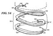
らせん針154
次に図5A及び図5Bを参照すると、らせん針154の図解が示されている。らせん針154は、前面部分502、本体部分504及びベース部分506を有した縫合針であってもよい。らせん針154は、当分野で既によく知られている標準の技法を使用して製造することができる。らせん針154は、ステンレス鋼から作ることができるが、当業者には明らかである他の適切な材料を使用することも可能である。
Referring now to FIGS. 5A and 5B, an illustration of the
いくつかの実施例では、らせん針154は、ばねのように圧縮し、或いは引き伸ばすことができるニチノールなどの材料から形成することができ、したがってらせん針154を圧縮し、或いは引き伸ばした後、荷重を解放する事によって元のらせん針154の状態に復帰させることができる。いくつかの実施例では、この特徴は、縫合領域156へのほぼ圧縮された状態でのらせん針154の輸送を容易にしている。 In some embodiments, the
本体部分504は、本体部分504から形成された複数の巻き157からなっていてもよい。個々の巻きは、らせん針を構成するらせん形のコイルを有することができる。これらの複数の巻き157は、ほぼ等間隔で離隔することができ、また、ほぼ平行に傾斜を付けることができ、したがってほぼ一定のピッチ及びほぼ一定の曲率半径を有するつる巻き線を形成している。これらの複数の巻き157は、らせん針154の一方の末端に位置している前面部分502から、反対側の末端に位置しているベース部分506まで延在することができる。 The
本体部分によって形成されるらせん形は、右巻きつる巻き線のらせん形であっても、或いは左巻きつる巻き線のらせん形であってもよい。図5に示されているらせん針154は、通常、左巻きつる巻き線のらせん針154である。左巻きらせん針にしなければならない場合、左巻きらせん針の複数のループの配向に対応するようにらせん針ハウジング128を適応させることができる。一例として図1、図2、図3、図4A及び図4Bは、右巻きらせん針を示したものである。 The spiral formed by the body portion may be a right-handed spiral or a left-handed spiral. The
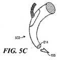
らせん針154は、さらに、断面積508を有することができ、この断面積508は、針本体504の長さ全体にわたって一様にすることができるが、らせん針154の前面部分502及びベース部分506で変更することができる。らせん針154の前面部分502は、針先155及び縫合糸結合レセプタ510を有することができる。図5Cに示されているように、針先155は、先細りになった形状を有することができ、針先155の断面514は、先端512から、針本体504の断面508と一致する形状まで、徐々に大きくなっている。針先155は、さらに、外科の必要性に応じて急峻な先端又は浅い先端を有することができる。 The
針本体504の長さは、針先155からベース部分506までの針本体部分に沿った距離としてとらえる事ができる。曲率半径は、針本体部分がほぼ一様な幅のらせんを形成するよう、複数のループ全体にわたってほぼ一様にすることができる。らせんピッチは、複数のループ間の間隔として定義することができ、また、らせん幅は、外部エッジ間の直線距離として定義することができ、また、らせん高さは、針ハウジング128の中に少なくとも部分的に嵌合するように構成することができる。さらに、これらの要素は、外科の必要性に応じて変更することができる。 The length of the
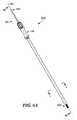
次に図5Dを参照すると、らせん針154の先端522の近接図が示されている。らせん針154は、さらに、縫合糸結合レセプタ510からなっている。縫合糸結合レセプタ510は、らせん針154の前面部分502の針先155に対して近位の位置に刻み目を有している。縫合糸結合レセプタ510は、縫合糸が、この説明の中で開示されている工程によって組織をまとめて束ねるために使用されるように、縫合糸に結合するように構成されている。 Referring now to FIG. 5D, a close-up view of the
図4A及び図4Bを参照すると、らせん針154のベース部分506は、接続部分159を有することができる。ステンレス鋼から製造することができるらせん針154と、成形可能プラスチックから製造することができる外部回転柱体104の間の結合は、同様の材料を接続する公知の方法によって達成することができる。例えば、接続部分159は、閉じた接地端を有することができ、したがってベース部分506に位置している複数の巻き157の巻は狭いピッチを有することができ、また、外部回転柱体104の接続部分410によって形成される平面に対して概ね平行の平面を形成する。また、ベース部分506に位置している複数の巻き157の巻の曲率半径も、接続を容易にするために、ほぼ外部回転柱体104の接続部分410の半径まで小さくすることができる。例えば、らせん針154の接続部分159は、外部回転柱体104の接続部分の湾曲した縁の内部に配置することができ、或いはらせん針154の接続部分を外部回転柱体104の接続部分の中に埋め込むことができる。 With reference to FIGS. 4A and 4B, the
縫合糸520
次に図5A、図5B、図5C及び図5Dを参照すると、縫合糸520は、らせん針154に接続するように構成されることができ、したがって吸引管126によって集められた胃の組織を縫合糸520によって束ねることができる。通常、縫合糸520は、少なくとも部分的に、無期限に胃の組織を保持するだけの十分に強力なバインディング能力の非吸収性材料からなることができる。このような材料には、それらに限定されないが、絹、ポリプロピレン、ポリエステル又はナイロンがある。また、縫合糸520は、抗菌物質でコーティングされた、流体に対して少なくとも半不浸透性である、非毒性、低アレルギー性の物質であることができる。これらの材料を使用した縫合糸は、当分野でよく知られており、また、代替実施例も同じ目的を果たし、ここで説明されている使用法を使用することができることは当業者には明らかであろう。
Referring now to FIGS. 5A, 5B, 5C and 5D, the
図5Bに示されている実施例では、縫合糸520はコイル縫合糸である。このような縫合糸は当分野で知られており、特定の長さ、引張り強さ及び弾性を有するように予め選択された材料からなっている。パッケージ済み縫合糸の他の実施例を使用することも可能である。この縫合糸は、特定の縫合糸が術の必要性に合致する限り、場合によっては交換可能であることは当分野では明らかであろう。 In the embodiment shown in FIG. 5B, the
縫合糸520は、さらに、らせん針154の針先155に接続することができる先端522、及び縫合糸交差結合部524に接続することができる後端523からなっていてもよい。縫合糸520は、先端522と後端523の間に縫合糸本体525を有している。縫合糸の先端522は、縫合糸結合部526によって針先155に結合することができ、また、後端523は、吸引管126に結合することができる。 The
縫合糸520の先端522は、少なくとも1つのアンカをさらに備えた縫合糸結合部526を有することができる。縫合糸結合部526は、縫合糸520を組織中に永久的に固定するために、ステンレス鋼などの金属材料から製造することができる。縫合糸結合部526は、同じ目的を達成することができる他の材料から製造することも可能であることは当業者には明らかであろう。 The
縫合糸結合部526は、縫合糸結合部526の形状が針の傾斜と共に流線形をなすように縫合糸結合レセプタ510中に嵌合するように形成されている。この構成によれば、らせん針154が胃の組織中に前進する際に、縫合糸結合部526を縫合糸結合レセプタ510の中に置くことができる。流線形にすることにより、らせん針154が前進する際の組織の破損及び引きずりを防止することができる。 The
針先155で、縫合糸結合レセプタ510は、縫合糸520の先端522に結合することができる。軽い接着材料を使用して縫合糸結合部526を一時的に縫合糸結合レセプタ510結合することができる。接続の持続は一時的なものであるため、縫合糸520が胃の物質と係合すると、縫合糸結合部526は、縫合糸結合レセプタ510から解放される事ができ、また、アンカを胃の物質と係合させ、縫合糸520を所定の位置に残し、且つ、この説明の中で開示されている工程によってらせん針154を後退させることができる。 At the
縫合糸本体525の縦軸線に沿って取った、先端522から後端523までの縫合糸520の長さは、らせん針154の長さとほぼ同じ長さになるように構成することができる。いくつかの実施例では、らせん針124からの縫合糸の分離を可能にするために、縫合糸520の長さを短くすることができる。 The length of the
第2の胃縮小装置1000
次に図6Aを参照すると、第2の胃縮小装置1000の少なくとも1つの実施例が示されている。図6Bには、第2の胃縮小装置1000の断面図が示されている。第2の胃縮小装置1000は、胃の第1の上部嚢と胃の第2の下部嚢の間に通路を画定するスリーブを生成するために、胃に組織拘束装置を送り込むように構成することができる。第1の嚢は、一般に、第2の嚢と比較すると、より小さい大きさを有することができるため、減量のための食糧材料の摂取量を調整することができる。Second
Referring now to FIG. 6A, at least one embodiment of a second
第2の胃縮小装置1000は、遠位端1002及び近位端1004を有することができる。遠位端1002は、身体内の組織にアクセスするために、口の中に挿入するように、或いは人体などの生体器官中に切り込むように構成することができる。近位端1004は、手術者がハンドル組立体1006及びコネクタ組立体1008を使用して操作し、且つ、装置を位置決めするために構成することができる。 The second
第2の胃縮小装置1000は、ほぼ装置軸線1001に沿って、近位端1004から遠位端1002まで延在することができる。第2の胃縮小装置1000の個々の構成部品を説明する際には、装置軸線1001の言及がなされる。 The second
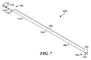
次に図7及び図8を参照すると、第2の胃縮小装置1000の構成部品の分解図が示されている。第2の胃縮小装置1000は、遠位端1002に、組織収集組立体1020及び縫合体組立体1070を有することができる。第2の胃縮小装置1000の装置本体1080は、ほぼ装置軸線1001に沿って延在している1つ以上の細長い管部材を有することができ、いくつかの実施例では、この1つ以上の細長い管部材は、本体内に組織収集組立体1020を配置し、且つ、縫合体組立体1070を駆動するために、遠位端1002及び近位端1004を接続するように機能している。 7 and 8, an exploded view of the components of the second
装置本体1080
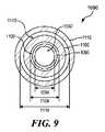
次に図9を参照すると、個々の管部材が他の管部材の中に嵌合する様子を示す装置本体1080の横断面図が示されている。本体1080の管部材は、内部管1090、縫合体ドライバ1100及び外部管1110を含むことができる。Device
Referring now to FIG. 9, there is shown a cross-sectional view of the
装置本体1080は、一般に、食道、胃、小腸又は大腸などの人体の口又は通路内の曲率に適応するために湾曲させることができる。いくつかの実施例では、装置本体1080は、手術者が第2の胃縮小装置1000を自由に操作することができる領域から胃などの少なくとも身体の目標部分に到達するよう、手術者に手動アクセスを与えるように構成された長さを有することができる。 The
装置本体1080は、吸引力又は真空力などの組織収集力を伝達するための内部管1090を有することができる。いくつかの実施例では、内部管1090は、遠位端で組織収集組立体に結合し、また、近位端でハンドル組立体1006及びコネクタ組立体1008に結合するように構成された細長い円筒状中空管を有することができる。内部管1090は、内部管1090の近位端から遠位端まで延在している内部管通路1092を画定することができる。さらに、内部管通路1092の近位端の開放端には真空源(図示せず)を結合することができる。内部管1090は、ポリ(テトラフルオロエチレン)(PTFE)などのプラスチック、或いは当業者に広く知られている化学的に不活性の他の可撓性材料から製造することができる。 The
内部管通路1092は、第2の胃縮小装置1000の遠位端で胃の組織を該装置に収集するのに必要な吸引力の大きさに適応するように構成することができる内部管通路径1094を有することができる。内部管通路径1094は、内部管通路1092の断面の直径である。内部管通路径1094は、圧力及び吸引力を変化させるために変更することができることは当業者には理解されよう。内部管通路径1094は、通路、空気流に影響を及ぼす可能性のある内部管1090の近位端又は遠位端のあらゆるアタッチメントを通過する空気の速度などの他の変数、或いは当業者に広く知られている他の任意の変数と相俟った一要素であってもよい。
装置本体1080は、さらに、縫合体1040を駆動するための縫合体ドライバ1100を有することができる。いくつかの実施例では、縫合体ドライバ1100は、内部管1090の遠位端で駆動するために縫合体1040に結合し、また、近位端でハンドル組立体1006及びコネクタ組立体1008(図6Aに示されている)に結合するために、ドライバ通路1102の中に内部管1090を受け入れることができる細長い波形管を有することができる。ドライバ径1104は、スライド可能に嵌合し、且つ、ドライバ通路1102の内壁内に内部管1090を受け入れるように構成することができる。ドライバ通路1102の内壁と内部管1090の外壁の間には、内部管1090上での縫合体ドライバ1100の回転を許すためのクリアランスが存在していてもよい。 The apparatus
縫合体ドライバ1100は、内部管1090と共に湾曲させることができ、さらに、縫合体1040を回転させるためにねじることも可能である。さらに、縫合体ドライバ1100が波形1101(図25、図31に示されている)であるため、使用者が縫合体ドライバ1100の近位端で縫合体ドライバ1100を回転させ、或いはねじる際の柔軟性及び支持が縫合体ドライバ1100に提供される。縫合体ドライバ1100は、ポリ(テトラフルオロエチレン)(PTFE)などのプラスチック、或いは化学的に不活性の他の可撓性材料から製造することができ、また、ステンレス鋼又は他の金属で補強することができる。当業者には、他のプラスチック材料及び金属材料を縫合体ドライバ1100に利用することも可能であることを理解されたい。 The
本体1080は、さらに、内部管1090、縫合体ドライバ1100、及び組織収集装置1020及び縫合体組立体1070などの近位端1002の構成部品を収納するための外部管1110を有することができる。外部管1110は、少なくとも部分的に、縫合体ドライバ1100を身体組織及び流体から密閉するために、外部管通路1112の中に縫合体ドライバ1100及び内部管1090を受け入れることができる細長い円筒状中空管であることができる。外部管1110は、Tygothane(登録商標)などの精密ポリウレタン配管、又は他の化学的に不活性の可撓性材料から製造される。 The
外部管通路1114は、縫合体組立体1070を収納し、且つ、駆動するようにすることができる。外部管通路1114は、縫合体ドライバ1100を回転させるようにすることができ、また、外部管通路1114の内壁と縫合体ドライバ1100の外部表面の間のクリアランスを含むことができる。 The
外部管1110は、近位端でハンドル組立体(図7及び図8の分解図に示されている)に結合し、また、(図18に示されているように)遠位端で縫合体コネクタ1060に結合するように構成することができる。外部管1110は、縫合体ドライバ1100及び内部管1090と共に湾曲させることができ、また、外部管通路1112内における縫合体ドライバ1100のねじり及び回転を許すように構成することができる。 The
内部管1090、縫合体ドライバ1100及び外部管1110は、それぞれ、個々の管1090、1100及び1110の近位端から遠位端にわたる長さを有することができる。個々の管の長さは、第2の胃縮小装置1000の動作に適応させるべく、互いに調和させることができる。通常、外部管1110は、縫合体ドライバ1100を外部管から延在させて組織収集組立体1070を位置決めすることができるように、これらの3つの管1090、1100及び1110のうち、最も短い長さを有することができる。
内部管1090は、通常、縫合体ドライバ1100又は外部管1110のうちのいずれかよりも長い長さを有することができる。一例として、平均的な大人に適応するために、内部管1090の長さは、97cm(38.2インチ)の値を有することができる。内部管1090のこの長さは、真空源への内部管1090の接続に適応することも可能である。一例として、縫合体ドライバ1100及び外部管1110の長さは、それぞれ81cm(31.9インチ)及び72cm(28.3インチ)の長さを有することができる。当業者には、大きさが異なる患者に対する第2の胃縮小装置1000のアクセス性に適応するために、これらの長さを変更することができることを理解されたい。
ハンドル組立体1006
第2の胃縮小装置1000の近位端1004では、ハンドル組立体1006は、ハンドル部材1120、第1のインサート1130、第2のインサート1140及びアクチュエータ1150を有している。いくつかの実施例では、ハンドル組立体は、手術者が第2の胃縮小装置1000を操作し、且つ、縫合体組立体1070を駆動するための機構を提供することができる。
At the
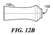
次に図10、図11、図12A及び図12Bを参照すると、図10にはハンドル組立体1006の横断面図が示されており、また、図11、図12A及び図12Bには、ハンドル部材1120の斜視図、背面図及び側面図がそれぞれ示されている。いくつかの実施例では、ハンドル部材1120は、概ね中空にすることができ、また、少なくとも部分的に、第1のインサート1130及び第2のインサート1140を収納するように構成することができる。 Referring now to FIGS. 10, 11, 12A and 12B, FIG. 10 shows a cross-sectional view of the
ハンドル部材1120は、装置軸線1001(図8に示されている)に沿って延在している第1のハンドル孔1122を有することができ、この第1のハンドル孔1122は、縫合体ドライバ1100及び内部管1090の通過を可能にするために、遠位端の開口からハンドル部材1120を貫通している。図10に示されているように、外部管1110の近位端は、ハンドル部材1120の遠位端部分又はその近傍に第1のハンドル孔1122で結合することができる。いくつかの実施例では、外部管1110の近位端のリム部分1116(同じく図8に示されている)を第1のインサート1130の遠位端に当接させることができるよう、第1のハンドル孔1122の内部表面を外部管1110の外部表面に接着することができる。 The
ハンドル部材1120は、人間のグリップに適応し、手術者が第2の胃縮小装置1000を操作することができるよう、湾曲した形状又は輪郭を有することができる。ハンドル部材1120は、アクリロニトリル・ブタジエン・スチレン(ABS)プラスチック樹脂などのプラスチック又は他の硬質材料から製造することができる。 The
次に図10、図11、図13A、図13Bを参照すると、図10にはハンドル組立体1006の横断面図が示されており、また、図11、図13A及び図13Bには、第1のインサート1130の斜視図、正面図及び側面図がそれぞれ示されている。第1のインサート1130は、外部管1110をハンドル部材1120に結合するための概ね中空の円筒状部材を有することができる。 Referring now to FIGS. 10, 11, 13A, and 13B, FIG. 10 shows a cross-sectional view of the
第1のインサート1130は、ハンドル部材1120の近位端からハンドル部材1120の第1のハンドル孔1122の中に嵌合させることができ、また、図10に示されているように、第1のハンドル孔1122の内部表面の出っ張り1124に当接させることができ、それによりハンドル部材1120中への第1のインサート1130のそれ以上の移行を停止することができる。いくつかの実施例では、ハンドル部材1120の孔1122の対応する内部表面に第1のインサート1130の外部表面を接着することができる。溝1132は、第1のインサート1130の外側の表面に沿って延在させることができる。これらの溝1132は、第1のインサート1130の相対回転を防止するために、ハンドル部材1120の内部表面のタブ又はリブ1126の中に嵌合させることができる。 The
いくつかの実施例では、第1のインサート1130は、縫合体ドライバ1100及び内部管1090のための通路を提供するために、円筒状部材の中空部分を通って延在している第1のインサート孔1134を有することができる。第1のインサート孔1134を画定している表面は、第2のインサート1140を受け入れるためのねじ1136を有することができる。第1のインサート1130は、デルリン(登録商標)又は当業者に知られている他の樹脂を含む他の同様の材料から製造することができる。 In some embodiments, the
次に図14、図15A及び図15Bを参照すると、アクチュエータ1150の斜視図、背面図及び側面図がそれぞれ示されている。いくつかの実施例では、アクチュエータ1150は、縫合体ドライバ1100を駆動するためのノブ形部材を有することができる。通常、アクチュエータ1150は、中空の円筒形状を有することができ、また、アクチュエータ1150の外側の表面に沿って延在している、手術者がアクチュエータ1150を回転させるための握り表面を提供するための刻み目1152を有することができる。アクチュエータ1150は、アクリロニトリル・ブタジエン・スチレン(ABS)プラスチック樹脂などのプラスチック又は他の硬質材料から製造することができる。 14, 15A and 15B, there are shown a perspective view, a rear view and a side view of the
アクチュエータ孔1154は、アクチュエータ1150の中心を通っている装置軸線1001に沿って延在することができる。アクチュエータ孔1154は、少なくとも部分的に第2のインサート1140と嵌合して受け入れるように構成及び大きさにすることができる。アクチュエータ1150は、手術者から縫合体に回転力を伝達するために、第2のインサート1140に結合するように構成することができる。 The
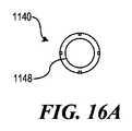
次に図14、図16A及び図16Bを参照すると、第2のインサート1140の斜視図、背面図及び側面図がそれぞれ示されている。いくつかの実施例では、第2のインサート1140は、縫合体ドライバ1100を駆動するための概ね円筒状の中空部材である。第2のインサートは、外側の表面の少なくとも一部に、ねじが切られた第1の部分1142を有することができる。第2のインサート1140のこのねじが切られた第1の部分1142は、第1のインサート1130のねじ1136にねじ込み可能に結合することができる。第2のインサート1140は、アルミニウムなどの金属から製造することができる。 Referring now to FIGS. 14, 16A and 16B, there are shown a perspective view, a rear view and a side view of the
第2のインサート1140は、さらに、第2のインサート1140の外側の表面の第2の部分1144を有することができる。この第2の部分1144は、装置軸線1001(図8に示されているように)に沿って長さ方向に延在している1つ以上の溝1146を有するほぼ滑らかな表面を有することができる。第2の部分1144は、アクチュエータ1150のアクチュエータ孔1154の中に嵌合するように構成及び大きさにすることができる。 The
図10を参照すると、いくつかの実施例では、アクチュエータ孔1154を画定している内部表面に第2の部分1144を接着することができる。また、アクチュエータ孔の内部表面は、アクチュエータ孔1154内における第2のインサート1140の軸線方向の移行を防止するように構成された1つ以上のエッジ表面1156を有することも可能である。第2のインサート1140の溝1146は、第2のインサート1140がアクチュエータ孔1154の中に嵌合すると、アクチュエータ孔1154の内部表面から延在しているタブ又はリブ(図示せず)を受け入れることができる。溝1146は、第2のインサート1140の相対回転の防止を補助することができる。 Referring to FIG. 10, in some embodiments, the
いくつかの実施例では、第2のインサート1140は、さらに、縫合体ドライバ1100のための結合表面を提供するための第2のインサート孔1148を有することができる。この第2のインサート孔1148は、第2のインサート1140を貫通して、ほぼ装置軸線1001に沿って長さ方向に延在することができる。 In some examples, the
図10を参照すると、縫合体ドライバ1100及び内部管1090は、少なくとも部分的に第2のインサート孔1148を通過することができる。縫合体ドライバ1100は、らせん縫合体1040のための駆動力をアクチュエータ1150から縫合体ドライバ1100まで伝達するために(図8に示されているように)、第2のインサート孔1148の内部表面に取り付けることができる。内部管1090は、第2のインサート孔1148を通過することができるため、内部管1090を真空源(図示せず)に結合することができる。 Referring to FIG. 10, the
縫合体組立体1070
次に図17を参照すると、らせん縫合体1040に結合された縫合体コネクタ1060を有することができる縫合体組立体1070の斜視図が示されている。らせん縫合体1040は、いくつかの実施例では、縫合体コネクタ1060によって縫合体ドライバ1100に解放可能に結合することができる。らせん縫合体1040と縫合体コネクタ1060の間の接続は、らせん縫合体1040を胃の組織中に前進させるための回転力が縫合体コネクタ1060によってらせん縫合体1040に提供されるように構成することができる。また、縫合体コネクタ1060は、らせん縫合体1040から分離するように構成することも可能である。
Referring now to FIG. 17, a perspective view of a
次に図18を参照すると、組織収集組立体1020に結合された縫合体組立体1070(図17に示されているような)の横断面図が示されている。らせん縫合体1040は、いくつかの実施例では、縫合体コネクタ1060によって縫合体ドライバ1100に結合することができる。組織収集組立体1020は、胃の内壁の組織を束ねるために、組織を第2の胃縮小装置1000の近傍又は第2の胃縮小装置1000に集めるための真空力を提供することができる。縫合体組立体1070は、胃の組織をほぼ通路にするための構造を提供することができる。いくつかの実施例では、縫合体組立体1070は、少なくとも部分的に、組織収集組立体1020上で駆動される。 Referring now to FIG. 18, a cross-sectional view of a suture assembly 1070 (as shown in FIG. 17) coupled to a
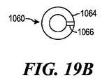
次に図19A及び図19Bを参照すると、縫合体コネクタ1060の側面図及び上面図が示されている。縫合体コネクタ1060は、通常、概ね円筒状を有する第1の部分1062、及び半径が概ねに第1の部分1062の半径より大きい、ほぼ板の形状を有する第2の部分1064でできたプラグを有することができる。縫合体コネクタ1060は、ステンレス鋼又は身体内での使用に適した他の金属から製造することができる。 Referring now to FIGS. 19A and 19B, side and top views of
図18を参照すると、縫合体コネクタ1060の第1の部分1062は、縫合体ドライバ1100内の通路の中、及び内部管1090の上に嵌合するように構成することができる。いくつかの実施例では、第1の部分1062の外側の表面は、縫合体ドライバ1100の遠位端で縫合体ドライバ1100の内側の表面に結合することができ、特定の実施例では、この結合は、接着によって固着することができる。遠位端のエッジ部分は、縫合糸コネクタ1060の第2の部分1064の下面1063に当接させることができる。 Referring to FIG. 18, the
第2の部分1064は、少なくとも部分的に縫合体ドライバ1100の通路及びエッジ部分を覆うことができる。いくつかの実施例では、この第2の部分1064は、縫合体ドライバ1100のドライバ通路1102(図9に示されているような)に組織が入り込み、或いは流体が流入するのを防止するために、縫合体ドライバ1100の遠位端のシールを提供することができる。 The
図17を参照すると、第2の部分1064の上面は、タブ部分1066を有するほぼ平らな表面を有することができ、この表面は、らせん縫合体1040を縫合体コネクタ1060に結合するための表面としての役割を果たすことができる。また、タブ部分1066は、らせん縫合体1040を前進させるためのプッシュ表面を提供することができる。らせん縫合体1040は、タブ部分1066又はその近傍で縫合体コネクタ1060に結合することができる。 Referring to FIG. 17, the top surface of the
らせん縫合体1040
次に図20A及び図20Bを参照すると、らせん縫合体1040のための一実施例の側面図及び底面図が示されている。らせん縫合体1040は、図2及び図18に示されている縫合領域156にもたらされた胃の組織中に前進することができる。らせん縫合体1040は、胃スリーブのための剛直な構造を形成し、摂取された物質を通過させるための管腔又は通路を生成することができる。
Referring now to FIGS. 20A and 20B, a side view and bottom view of one embodiment for a
らせん縫合体1040は、近位端1042、遠位端1043及び本体部分1046を有することができる。らせん縫合体1040は、当分野で既によく知られている標準の技法を使用して製造することができる。らせん縫合体1040は、ステンレス鋼から構築することができるが、当業者には明らかであるほぼ剛直な他の適切な材料を使用することも可能である。 The
本体部分1046は、本体部分1046から形成される複数の巻1047からなっていてもよい。個々の巻は、らせん縫合体1046を構成するほぼらせん形のコイルを有することができる。これらの複数の巻1047は、ほぼ等間隔で離隔することができ、また、ほぼ平行に傾斜を付けることができ、したがってほぼ一定のピッチ及びほぼ一定の曲率半径を有するつる巻き線を形成している。これらの複数の巻1047は、遠位端1043から近位端1042まで延在させることができる。
いくつかの実施例では、らせん縫合体1040は、ばねのように圧縮し、且つ、引き伸ばすことができる材料から形成することができ、したがってらせん縫合体1040を引き伸ばし、或いは圧縮した後、荷重を解放する事によって元のらせん縫合体1040の状態に復帰させることができる。他の実施例では、らせん縫合体は、曲率半径を小さくし、又は大きくすることができ、1つ以上の巻のピッチを狭くし、又は広くすることができ、或いはらせん縫合体全体の長さを短くし、又は長くすることができる材料から形成することができる。胃の組織にしっかりと定着すると、らせん縫合体1040の形状をひずませることになる能動胃力が、らせん縫合体1040に対して半径方向又は軸線方向に作用し、それにより一般的にはらせん縫合体1040の構造が伸長することになる。 In some embodiments, the
本体部分1046によって形成されるらせん形は、右巻きつる巻き線のらせん形であっても、或いは左巻きつる巻き線のらせん形であってもよい。図17に示されているらせん縫合体1040は、通常、右巻きつる巻き線のらせん縫合体1040である。左巻きらせん針にしなければならない場合、左巻きらせん針の複数のループの配向に対応するように第2の胃縮小装置1000の構成を適応させることができる。例えば、左巻きらせん縫合体の駆動に適応するために、第1のインサート1130及び第2のインサート1140の少なくともねじの方向を逆にすることができる。 The spiral formed by the
らせん縫合体1040は、さらに、図18に示されているように、概ね円形の断面積1041を有することができ、この断面積1041は、縫合体本体部分1046の長さ全体にわたって一様にすることができるが、らせん縫合体1040の近位端1042及び遠位端1043で変更することができる。らせん縫合体1040の遠位端1043は、縫合体先端1044を有することができる。縫合体先端1044は、先細りになった形状を有することができ、縫合体先端1044の断面1041は、先端から、本体部分1046の断面1041と一致する形状まで、徐々に大きくなっている。縫合体先端1044は、さらに、外科の必要性に応じて急峻な先端又は浅い先端を有することができる。 The
近位端1042は、断面積1041と同様の断面を有することができ、或いはいくつかの実施例では、近位端1042と縫合体コネクタ1060の頂部表面との間の接触面積を広くするために変更することも可能である。接触面積を広くすることにより、らせん縫合体をコネクタ1060に結合するためのより広い表面積を提供することができる。
縫合体本体部分1046の長さは、先端1044の先端から近位端1042までの縫合体本体部分に沿った距離としてとらえる事ができる。曲率半径「r」は、針本体部分がほぼ一様な幅のらせんを形成するよう、複数のループ全体にわたってほぼ一様にすることができる。らせんピッチ及びらせん幅などの他の寸法は、内部管1090の上に嵌合するように構成することができる。さらに、これらの要素は、医療術及び患者の必要性に応じて変更することができる。 The length of the
らせん縫合体1040は、半径1045を有する縫合体通路1049を有することができる。縫合体通路1049は、らせん縫合体1040のループ1047から形成することができる。いくつかの実施例では、半径1045は、らせん縫合体1040のらせん形の曲率半径に対応していてもよい。この半径1045を提供することにより、集められた組織から第2の胃縮小装置1000まで管腔又は通路を生成することができる。集められた組織にしっかりと定着すると、らせん縫合体1040は、半永久的な胃スリーブを形成することができる。 The
らせん縫合体1040の半径1045は、胃の組織への貫入の所望の深さに適応するために、組織の所望の管腔の直径より大きくすることができる。貫入の深さは、らせん縫合体が少なくとも部分的に胃の筋肉壁の中に貫入するように選択することができる。組織を束ねることは、筋レベルでは場合によってはより安全であり、また、耐久性がある。貫入の深さが浅すぎる場合、束ねられた粘膜(非筋性)組織が保持されず、また、胃スリーブが破壊されることがある。 The
いくつかの実施例では、管腔の直径は、8〜12mm(0.315〜0.743インチ)の範囲を有することができる。実施された実験には、10mm(0.394インチ)の管腔径が首尾よく使用された。上に示した範囲には、本明細書において開示されている装置100及び1000によって組み込むことができる、或いは適応することができる管腔の直径を限定することは一切意図されていない。貫入の深さ及び半径1045に対する貫入の深さの関係については、真空柱体1162を参照して、以下でさらに説明する。 In some examples, the lumen diameter can have a range of 8-15 mm (0.315-0.743 inches). A 10 mm (0.394 inch) lumen diameter was successfully used in the experiments performed. The ranges given above are not intended to limit the diameter of the lumen that can be incorporated or accommodated by the
本明細書において開示されている実施例にらせん縫合体を使用することには、場合によっては特定の利点がある。らせん縫合体を使用することにより、組織を内部で束ねることができるため、堅固で、且つ、耐久性のある胃スリーブの保持を生成することができる所望の深さに貫入させることができる。らせん縫合体は、単一の連続運動で前進させることができるため、便宜上、手術者による術の完了を補助することができる。らせん縫合体によれば、少なくともいくつかの実施例では、貫入の深さがらせん縫合体の長さに沿って一様で、且つ、一定であるため、安定した耐久性のある縫合が得られる。らせん縫合体は、他の糸材料より強力であり、また、らせん縫合体の長さに沿って組織を切断し、或いは切り取る可能性を小さくすることができる。 The use of helical sutures in the embodiments disclosed herein has certain advantages in some cases. By using a helical suture, the tissue can be bundled internally so that it can be penetrated to a desired depth that can produce a rigid and durable gastric sleeve retention. Because the helical suture can be advanced in a single continuous motion, it can assist the operator in completing the procedure for convenience. According to the helical suture, in at least some embodiments, the penetration depth is uniform and constant along the length of the helical suture, resulting in a stable and durable suture. Helical sutures are stronger than other thread materials and can reduce the likelihood of cutting or cutting tissue along the length of the helical suture.
いくつかの実施例では、らせん縫合体1040は、ニチノール(ニッケル・チタン)又は他の同様の材料から構成されることが場合によっては望ましい。ニチノールは、圧縮され、或いはひずみが加えられた後に、その元の形状を保持することができる材料を含むことができる。いくつかの実施例では、らせん縫合体1040は、らせん縫合体1040を外部管1110の中に収納する際にはより小さい直径を有し、また、らせん縫合体1040を展開させる際にはその所望の形状に膨張することができるよう、ねじることができる。 In some embodiments, it may be desirable for the
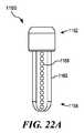
真空柱体1160
次に図21、図22A及び図22Bを参照すると、真空柱体1160のための一実施例の斜視図、側面図及び底面図が示されている。真空柱体1160は、真空接続端1162及び柱体遠位端1164を有することができる。真空接続端1162は、真空力を胃壁に伝達するための内部管1090を受け入れ、且つ、内部管1090に結合するように構成することができる。
Referring now to FIGS. 21, 22A and 22B, there are shown a perspective view, a side view and a bottom view of one embodiment for the
柱体遠位端1164は、概ね中空の円筒状柱体部分1163を有することができ、この円筒状柱体部分1163は、そのほぼ中心を通っている装置軸線1001に沿って長さ方向に延在している真空通路1161を有している。真空接続端1162から柱体遠位端1164までの柱体部分1163の長さは、胃の中への管腔又は通路の形成に適応するように構成することができる。 The columnar
真空接続端1162及び柱体遠位端は、1つの統合片として構築することができる。真空柱体1160は、ポリカーボネート又は当業者に知られている他の適切な材料から製造することができる。 The
真空柱体1160の装置軸線に沿って長さ方向に延在している1つ以上のセクション1166を有することができる。個々のセクション1166は、装置軸線1001に沿って延在している柱体部分1163の壁を有することができる。1つ以上のセクション1166は、柱体部分1163の円周全体を取り囲み、真空柱体の長さ方向軸線に対して概ね横方向に対向することができる。いくつかの実施例では、1つ以上のセクションは、胃を第2の胃縮小装置1000に引き寄せ、組織を縫合領域156に集めるための等しい円周力を胃の周囲組織に加えるように構成することができる。 There can be one or
いくつかの実施例では、個々のセクション1166は湾曲した表面1167を有することができ、例えば図22Bに示されているセクション1166の表面は、真空通路1161に向かって内側に湾曲している凹状表面を有している。個々のセクション1166の表面の曲率は、胃の組織を受け取り、且つ、図25〜図34に関連して以下で説明するように、胃をヒダの形態にするように適応させることができる。 In some embodiments,
湾曲した表面1167は、セクション深さ1171を有することができる。セクション深さ1171は、図22Bに示されている真空柱体1160の底面図で見た場合の、湾曲した表面1167の最も内側の部分と真空接続端1165のほぼ外部エッジとの間の距離として定義することができる。セクション深さ1171は、第2の胃縮小装置1000に吸引された組織にらせん縫合体1040が貫入することができる深さを有することができる。 The
もう一度図20Aを参照すると、らせん縫合体1040の半径1045は、第2の胃縮小装置1000に集められた組織に、セクション深さ1171又はそれに近い深さで貫入するように構成することができる。いくつかの実施例では、セクション深さ1171は、3.0〜5.0mm(0.12〜0.2インチ)の範囲を有することができる。実験では、4.1mm(0.16インチ)の深さで所望の量の組織が首尾よく達成された。ここで示されているセクション深さの上記範囲及び実例には、本明細書において開示されている実施例が適応することができる貫入深さの範囲を限定することは一切意図されていない。 Referring once again to FIG. 20A, the
次に図18、図21、図22A及び図22Bを参照すると、図21には真空柱体1160の斜視図、また、図22A及び図22Bには真空柱体1160の側面図及び底面図がそれぞれ示されている。個々のセクション1166の湾曲した表面1167は、1つ以上の延長部分1169によって少なくとも1つの面の側面に配置することができる。また、個々のセクション1166は、胃の内壁への吸引力の伝達を可能にするための1つ以上の真空開口1168を含むことも可能である。個々の開口1168は、いくつかの実施例では、吸引によって個々のセクション1166に組織を引き寄せるために、真空柱体1160中への空気又は他の流体を流入させるように構成することができる開口、スロット又は入口を有することができる。個々の真空開口1168は、真空力が同時に、且つ、均等に分布するように構成することができるが、胃の組織の1つの領域に一度ずつ選択的に真空を印加することも可能である。 Next, referring to FIGS. 18, 21, 22A and 22B, FIG. 21 is a perspective view of the
いくつかの実施例では、延長部分1169は、個々のセクション1166に組織を吸引する際に、組織を導くためのパーティション又はアームとしての役割を果たすことができる。例えば図21では、延長部分1169は、真空開口1168の配置を側面に置くことができ、したがって組織が真空柱体1160に引き寄せられると、延長部分1169は、組織の少なくとも一部を真空開口1168に導く。 In some embodiments, the
個々の延長部分1169は、開放ボウル又は開放パラボラを生成するために、個々の開口1168から延在させることができる。いくつかの実施例では、延長部分1169は、個々のセクション1166の個々の面を側面に配置することによって対で動作させることができ、したがって個々のセクション1166で組織をヒダの形態にすることができる。組織のヒダは、湾曲した表面1167及び延長部分1169の輪郭に概ね従うことになる。
いくつかの実施例では、延長部分1169は、真空柱体1160の周囲に組織を導くことができる表面積を広くするために、真空接続端1162の半径を通り越して到達することができる。延長部分を後退させて真空柱体1160上へのらせん縫合体1040の展開に適応させることも可能であることを理解されたい。 In some embodiments, the
個々の真空開口1168は、セクション1166の外部表面から真空通路1161の中へ延在させることができる。個々の真空開口1168は、組織を真空柱体1160の外部表面に引き寄せるために、湾曲した表面1167内に配置することができる。いくつかの実施例では、湾曲した表面1167の最も深いポイントに個々の開口1168を配置することができる。
いくつかの実施例では、個々のセクションは、複数の開口1168のアレイを有することができる。個々の開口1168は、概ね円形などの形状を有することができる。これらの開口は、真空柱体1160の柱体部分1163に沿って延在しているラインの中に配置することができる。 In some embodiments, an individual section can have an array of a plurality of
これらの開口の形状及び配置を変更することにより、吸引力によって組織を真空柱体1160に引き寄せる真空柱体1160の動作を調整することができることは理解されよう。これらの開口は、図1に関連して示し、且つ、説明したスロットなどのスロットを有することができる。これらのスロットは、直線、曲線又は螺旋の形で延在させることができる。これらのスロットは、さらに、互いに平行に、或いは互いにオフセットした角度で配置することができる。 It will be understood that by changing the shape and arrangement of these openings, the operation of the
真空通路1161は、真空接続端1162と内部管1090の間を結合することによって内部管1090に接続することができる。この結合には、真空接続端1162への内部管1090の遠位端の接着を含むことができるが、当業者に知られている他の方法を使用することも可能である。真空接続端1162は、半径が柱体部分1163の半径より大きく、且つ、らせん縫合体1040の少なくとも巻の半径より小さい真空接続孔1165を有する概ね中空の部材を有することができる。 The
内部管1090は、真空接続端1162の中に嵌合し、且つ、真空接続孔1165の少なくともいくつかの内部表面と当接するように構成することができる。内部管1090と真空接続端1162の間を結合することにより、真空力を伝達し、且つ、吸引された空気及び他の流体の開口1168から内部管1090の真空ポート中への流入を許すためのシールを形成することができる。 The
(図1にガイド・ワイヤ118として示されているような)ガイド・ワイヤを、第1の胃縮小装置100に関連して説明した方法及び形態と同様の方法及び形態で第2の胃縮小装置1000と共に使用することができる。真空柱体1160は、図18及び図22Bに示されているように、ガイド・ワイヤ開口1172を使用して構成することができる。ガイド・ワイヤ開口1172は、ガイド・ワイヤが内部管1090を通って第2の胃縮小装置1000の近位端へ通過するように、真空柱体1160の真空通路1161を開放するように構成することができる。ガイド・ワイヤ開口1172は、真空柱体1160内の真空圧力の損失を防止するために、ダイヤフラム型シールを使用して構成することができる。 A guidewire (as shown as
当業者には、第2の胃縮小装置1000の構成部品は、第1の胃縮小装置100の構成部品と交換することができることを理解されたい。例えば、上で説明した吸引管126は、第2の胃縮小装置1000と共に動作するように置換し、或いは修正することができる。 It should be understood by those skilled in the art that the components of the second
第2の胃縮小装置1000の動作位置
次に図23A、図23B、図23C及び図23Dを参照すると、第2の胃縮小装置1000のための4つの動作位置のシーケンスが示されている。以下、人体と関連した第2の胃縮小装置1000の使用方法について、以下の図25〜図34を参照してより詳細に説明する。図23Aでは、第2の胃縮小装置1000は、患者の口などの生体器官の口に第2の胃縮小装置1000を最初に挿入するための第1の位置に示されている。Operating position of second
この第1の位置では、組織収集組立体1020及び縫合体組立体1070は、外部管1110内に後退させることができる。患者の口又は器官の管を通して挿入している間、第2の胃縮小装置1000は、第2の胃縮小装置1000の動作している構成部品による組織の引きずり、或いは引き裂きを防止するために、第1の位置を維持することができる。 In this first position, the
第1の位置では、第2のインサート1140は、第1のインサート1130(図示せず)との係合が解除された状態を維持することができる。この位置では、アクチュエータ1150及び第2のインサート1140は、内部管1090の上を自由にスライドし、或いは移行することができる。 In the first position, the
また、第1の位置では、らせん縫合体1040は、内部管1090に沿ってアクチュエータ1150を移動させることによって、縫合体ハウジング領域1119内の真空柱体1160のほぼ近傍に配置することができ、したがってらせん縫合体1040は真空柱体に向かって移行する。 Also, in the first position, the
図23Bでは、第2の胃縮小装置1000に組織を集めるための力を身体組織に加えるための第2の位置に第2の胃縮小装置1000を置くために、組織収集組立体1020の真空柱体1160を外部管1110から前進させることができる。真空柱体1160は、(図21及び図22Aに示されているような)1つ以上の開口1168を介して空気又は流体を受け取るように配置することができる。 In FIG. 23B, the vacuum column of the
第1の位置から移行させるために、手術者は、内部管1090を外部管1110に対して距離「L」だけスライドさせ、真空柱体1160を外部管1110から前進させることができる。内部管が前進する距離Lには、組織を収集している間及び組織を縫合している間、外部管1110からの構造的な干渉を防止するために、外部管1110からの真空柱体1160のための適切なクリアランスを含むことができる。通常、距離Lは、ほぼ真空柱体1160の長さに等しくすることができる。 To move from the first position, the operator can slide the inner tube 1090 a distance “L” relative to the
図23Cでは、らせん縫合体1040は、外部管1110から、装置に吸引された胃からの組織と係合するための第3の位置に展開している。手術者は、第2のインサートがねじ込み可能に第1のインサート1130(図示せず)と係合するよう、アクチュエータ1150を移動させることができる。手術者は、らせん縫合体1040が真空柱体1160の上を前進するよう、アクチュエータ1150を回転させることができる。実際には、胃の組織は、らせん縫合体1040が真空柱体1160上を回転しながら移行する際に、らせん縫合体1040が組織に貫入してらせん縫合体1040を所望の深さで取り付けるよう、予め真空柱体1160に配置しておくことができる。 In FIG. 23C, the
図23Dでは、第2の胃縮小装置1000は、第4の位置で、取り付けられたらせん縫合体1040から引き離されている。手術者は、図33に関連して以下で説明するように、縫合体コネクタ1060部分における縫合体ドライバ1100とらせん縫合体1040の間の結合を打ち破るための引張り力を加える。真空柱体1160は、縫合通路1048からスライドさせることができる。第2の胃縮小装置1000は、患者の身体から抜き取ることができる。 In FIG. 23D, the second
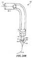
手術者を補助するための他の器具
図24A及び図24Bを参照すると、図1に示されている第1の胃縮小装置100は、さらに、手術者による、胃系統への第1の胃縮小装置100の挿入、或いは第1の胃縮小装置100の引抜きのいずれかに関わる損傷の抑制を補助することができる他の器具を含むことができる。このような他の器具は、第2の胃縮小装置1000と共に交換可能に使用することができることを理解されたい。Other Instruments to Assist the Surgeon Referring to FIGS. 24A and 24B, the first
例えば、挿入に際して、より滑らかな表面を提供するために導入鞘602を利用することができる。導入鞘602は、通路610を備えた可撓性中空円筒状管からなる。導入鞘は、胃装置の上をスライドさせて少なくとも部分的に胃装置を覆うことができる。導入鞘は、通路610内に外部回転柱体104、針ハウジング128及び吸引管126を嵌合させるだけの十分な広さの一様な直径を有することができる。導入鞘602は、第1の胃縮小装置100と組織の間の摩擦を小さくするために、その外側の表面をケイ素などの物質でコーティングすることができる。導入鞘602は、十分に可撓性にすることができ、したがって導入鞘602は、胃装置の他の部品と共に通過する際に湾曲し、同じ相対位置を維持する。 For example, the introducer sheath 602 can be utilized to provide a smoother surface upon insertion. The introduction sheath 602 consists of a flexible hollow cylindrical tube with a
いくつかの実施例では、図7に示されている、第2の胃縮小装置1000の外部管1110は、導入鞘602と同じ態様又は類似の態様で利用することができる。外部管1110は縫合体ドライバを保護し、また、縫合体組立体及び組織収集組立体を収納することができる。 In some embodiments, the
先細りになった先端バルーン604を導入鞘602と共に利用して、導入鞘602の少なくとも直径まで食道を拡張し、第1の胃縮小装置100の挿入を提供することができる。先細りになった先端バルーン604は、構造を拡張させるために使用され、また、先細りになった末端612及び鈍い末端614を有するように構成され、先細りになった先端バルーン604に概ね円錐状の形状を与える、商用的に入手することができる標準の食道バルーン又は幽門バルーンを有することができる。鈍い末端614は、吸引管126に接続するように構成することができ、また、さらに、先細りになった先端バルーンを膨らまし、或いはしぼませることができる空気入口616を有することができる。さらに、鈍い末端614は、鈍い末端から先細りになった末端まで内視鏡装置を通過させ、且つ、ガイド・ワイヤ出口613Bでバルーンから取り出すことができるガイド・ワイヤ入口613A(図示せず)を有することも可能である。 A tapered
先細りになった先端バルーン604は、管先端134の代わりに吸引管126の管本体136に結合することができる。いくつかの実施例では、密閉された開口がバルーン管604の通過及びガイド・ワイヤ管119(図示せず)の通過を許すことができる点を除き、吸引管126の遠位端の一部に蓋をして真空を密閉することができる。また、先細りになった先端バルーン604は、内部真空管110の空洞120を遠位端112から近位端110まで通すことができるバルーン管606に結合することも可能である。 The tapered
バルーン管606は、先細りになった先端バルーン604に結合する遠位端606a、及び内部真空管102の近位端110の上に配置されたバルーン・ポート608に結合する近位端606bを有することができる。バルーン管606は、先細りになった先端バルーン134の吸入及び排気のための個別の隔離通路を提供している。バルーン・ポート608は、先細りになった先端バルーン604を必要に応じて膨らませ、或いはしぼませることができる空気源(図示せず)に結合することができる。 The
いくつかの実施例では、吸引管126の管本体136は、真空源から密閉され、且つ、バルーン管606の通過及びガイド・ワイヤ管119の通過を許すように構成される吸引管126の遠位端に配置された領域を有することができる(図6Bに示されているような)バルーン収縮部分620を使用して構成することができる。バルーン収縮部分620は、キャップ620Aで吸引管126に蓋をし、且つ、密閉する吸引管126のはめ込み部分を有することができる。キャップ620Aは、吸引管126の中にセットされ、先細りになった先端バルーン604がしぼむと、先細りになった先端バルーン604を吸引管126の中に保管することができるような大きさにされている。また、キャップ620Aは、バルーン管開口622及びガイド・ワイヤ開口624を有することも可能であり、これらは、バルーン管606及びガイド・ワイヤ118、或いはガイド・ワイヤ118の通過を許すように構成することができる。先細りになった先端バルーン604をバルーン収縮部分620にしぼませることにより、胃の組織を吸引する際に、しぼんだ、先細りになった先端バルーン604が胃の組織を妨害するのを防止することができる。 In some embodiments, the
胃の大きさを小さくするための方法
次に図25〜図34を参照すると、本発明の特定の態様は、1つ以上の実施例では、胃の大きさを小さくする方法を開示している。通常、これらの方法は、食物のためのより狭い空間を提供し、患者の摂取食物容量を最適に小さくするために、胃の大きさの縮小を達成することができる。いくつかの実施例では、ここで開示されている方法には、胃壁の一部を集め、次に、集められた胃壁の部分を通して縫合部に糸を通すことによってそれらを束ね、それにより胃のその部分を通過する食物通路を狭くする吸引装置などの組織収集装置の使用が含まれている。一例として、これらの方法に使用される吸引装置は、この説明の中で開示されている第1の胃縮小装置100であっても、或いは第2の胃縮小装置1000であってもよい。これらの方法は、その方法の実践を特定の装置に限定することなく、この説明の中で開示されている第2の胃縮小装置1000を参照して説明されている。しかしながら、これらの方法は、開示されている工程と同じ工程又は類似の工程を達成することができる他の装置を利用することも可能である。また、ここで開示されている方法は、任意選択で、患者の医療の必要性に応じて他の胃縮小手順と共に使用することも可能である。Method for Reducing Gastric Size Referring now to FIGS. 25-34, certain aspects of the present invention, in one or more embodiments, disclose a method for reducing the size of the stomach. . Typically, these methods provide a narrower space for food and can achieve a reduction in stomach size to optimally reduce the patient's ingested food volume. In some embodiments, the disclosed method includes collecting portions of the stomach wall and then bundling them by threading the suture through the collected portions of the stomach wall, thereby causing the gastric The use of a tissue collection device such as a suction device that narrows the food passage through the portion is included. As an example, the suction device used in these methods may be the first
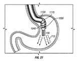
特定の図25〜図34では、分かり易くするために、或いは他の部品のために見えない位置に位置している部品をより明確に示すために、特定の部品が切り欠かれ、或いは隠されている。図27〜図33では、下方に位置している構造を示すために、縫合体コネクタ1060が切り欠かれている。これらの図解には、図に示されている装置を限定することは一切意図されていない。 In particular FIGS. 25-34, certain parts are notched or hidden for clarity or to more clearly show parts that are located invisible for other parts. ing. 27-33, the
最初に、手術者又は他の治療監督者は、患者の解剖学的な必要性及び治療の必要性に基づいて第2の胃縮小装置1000の構成を予め選択することができる。手術者又は他の治療監督者は、所与の患者に適応するために、必要な胃縮小装置の寸法を決定することができる。 Initially, an operator or other treatment supervisor can pre-select the configuration of the second
例えば、手術者は、患者の食道の長さ及び胃の大きさに応じて、縫合位置に位置した場合に真空柱体1160及びらせん縫合体1040などの縫合を延在させることができる距離を考慮して外部管の長さを決定することができる。 For example, depending on the length of the patient's esophagus and the size of the stomach, the operator may consider the distance that the sutures such as the
手術者は、いくつかの実施例では第2の胃縮小装置1000に使用される吸引管126の長さ及び対応する縫合の長さ、例えばらせん縫合体1040の長さを決定することができ、或いはいくつかの実施例では第1の胃縮小装置100に使用されるらせん針154及び縫合糸520の長さを決定することができる。縫合の長さによって、束ねるべき組織の量及び胃の大きさを所望の大きさに縮小する量を確立することができる。手術者は、さらに、食道に近い胃の部分に対する装置の配置を選択することができる。また、手術者は、任意選択で、患者への外傷を抑制するために、図24A及び図24Bに示されているような導入鞘602及び先細先端バルーン604の利用を選択することができる。 The surgeon can determine the length of the
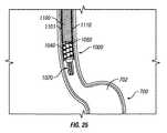
標準鎮静技法を含む標準の事前外科準備が完了すると、患者の中にガイド・ワイヤ118(図示せず)を配置して第2の胃縮小装置1000の配置を補助することにより、図25に示されている方法を開始することができる。図には示されていないが、内視鏡装置をガイド・ワイヤ118上をスライドさせて患者の胃700の中へ送り込むことができる。このような技法は、当分野では内視鏡検査法として知られており、一般に、内部表面から手術者に視覚画像を送る手段を備えた装置を使用した器官の直接評価又は間接評価と呼ばれている。内視鏡を使用して、第2の胃縮小装置1000を配置するための手引きを手術者に提供することができる。さらに、手術者は、第2の胃縮小装置1000の放射線不透性エレメントを利用した透視検査法などの他の間接観察技法を利用することも可能であり、それによりらせん縫合体1040を有利な位置に配置して術を完了することも可能である。 Once standard pre-surgical preparation, including standard sedation techniques, is completed, a guide wire 118 (not shown) is placed in the patient to assist in the placement of the second
次に図25〜図34を参照すると、胃の容積を小さくするための少なくとも1つの実施例による方法の図解が示されている。第2の胃縮小装置1000を配置すべき胃の中の部位を手術者が評価し、或いは第2の胃縮小装置1000を配置するために手術者が予め選択した部位の近傍を手術者が評価すると、食道を介して患者の胃の中に第2の胃縮小装置1000を挿入することができる。特定の実施例では、ガイド・ワイヤ(図示せず)を介して第2の胃縮小装置1000を挿入して通過させることにより、ガイド・ワイヤを介して第2の胃縮小装置1000を前進させることができる。 Referring now to FIGS. 25-34, an illustration of a method according to at least one embodiment for reducing stomach volume is shown. The surgeon evaluates the site in the stomach where the second
第2の胃縮小装置1000は、図25に示されている後退位置で食道を通過することができる。いくつかの実施例では、図23Bに示されているように、第2の胃縮小装置1000は、組織収集組立体1020が外部管1110の遠位端から延在している第2の位置で挿入することができる。第2の胃縮小装置1000は、真空柱体1160が少なくとも部分的に外部管1110から前進するように構成することができる。この位置では、らせん縫合体1140は、縫合体ドライバ・コネクタ1060部分で縫合体ドライバ1100に結合される。 The second
図26に示されているように、手術者は、食道を介して、胃嚢702内の、胃の頂部に対して所定の深さに第2の胃縮小装置1000を配置することができる。手術者は、遠位端1002の縫合領域156が、手術者が束ねることを決定した胃壁の部分704の近傍に位置するように第2の胃縮小装置1000を配置することができる。手術者による必要な深さへの真空柱体1160の配置を補助するために、マーキング164(図1に示されている)と同様のマーキングを第2の胃縮小装置1000の上に配置することができる。 As shown in FIG. 26, the operator can place the second
真空柱体1160は、患者の頭部から尾側方向に足指まで延在している身体の縦軸線に沿って胃700の中へ前進させることができる。真空柱体1160は、真空開口が概ね壁部分704と対向し、真空力が十分に加えられるように配向することができる。胃700の解剖学的な曲率は、真空開口を配向するためには、身体の縦軸線からの真空柱体1160のある程度の角偏向を余儀なくすることがある。 The
図27に示されているように、内視鏡1170は、内部管1090の上を、縫合体ドライバ1100内を通過させることができ、それにより内視鏡1170又は胃の内壁を照明し、且つ、検出する他の観察装置を配置することができる。内視鏡1170は、胃の内部を照明するための光源を提供することができる(図27に波線712で示されている)。また、手術者は、第2の胃縮小装置1000を配置するために、らせん縫合体1040及び縫合体ドライブ・コネクタ1060などの透視手段及び任意の放射線不透性エレメントを利用することも可能である。 As shown in FIG. 27, the
いくつかの実施例では、導入鞘602又は先細り先端バルーン604を利用することができる。図24A及び図24Bに示されているように、導入鞘602は、患者への挿入に先立って第1の胃縮小装置100の上に嵌合させることができ、且つ、装置100の上を外部回転柱体104の近位端402から遠位端404までスライドさせることができ、また、らせん針ハウジング128及び吸引管126の上をスライドさせることができる。導入鞘602と共に、先細り先端バルーンを利用することができる。第2の胃縮小装置1000は、先細り先端バルーン604を受け入れるように予め構成することができ、また、管先端134を置き換えることができる。挿入に先立って、また、導入鞘602の設置と共に、先細り先端バルーン604を、バルーン・ポート608に接続されたそのバルーン管606を介して膨らますことができる。 In some embodiments, an introducer sheath 602 or a tapered
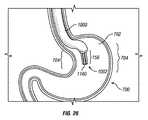
次に図28を参照すると、所定の位置に配置されると、第2の胃縮小装置1000は、胃の空洞702に連続吸引を加えることができる。一例として、約2分間にわたって約80mmHg(3.15インチHg)の圧力で吸引を加えることができる。これは、胃壁の部分704を第2の胃縮小装置1000に向かってへこますことができる吸引力であり、部分702を縫合領域156(図27に示されている)に引き寄せ、或いは強制する。いくつかの実施例では、真空柱体1160のセクション1166は、1つ以上の胃壁部分704を真空柱体1160の個々のセクション1166に引き寄せることができる。個々の胃壁部分704は、胃の組織中にヒダを形成することができ、個々のヒダは、胃壁部分704の湾曲即ち折重ねを有している。 Referring now to FIG. 28, when in place, the second
胃壁部分704のヒダは、真空柱体1160の円周の周囲に通路又は管腔706を形成することができる。真空柱体1160を介して加えられる吸引力は、胃の少なくとも一部をへこますための1つ以上のヒダを壁部分704に生成することができる。 The folds in the
次に図29及び図30を参照すると、胃嚢702の全円周を吸引力によって真空柱体1160に引き寄せることができる。壁部分704は、個々の胃壁部分704が真空柱体1160と接触するようにすることができる。 Next, referring to FIG. 29 and FIG. 30, the entire circumference of the
いくつかの実施例では、1つ以上のガイド(図示せず)が胃壁部分704の位置決め及び通路706の形成を補助することができる。他の実施例では、延長部分1169(図21及び図22Bに示されている)は、通路706を形成するためのガイドとして機能することができる。通路706は、胃の上部嚢708と下部嚢710を接続することができ、通常、上部嚢708は、下部嚢710より比較的小さい容積を有している。 In some embodiments, one or more guides (not shown) can assist in positioning the
次に図31を参照すると、縫合領域156は、第2の胃縮小装置1000によって胃壁の部分704と係合し、且つ、束ねることができる複数の真空開口1168の近傍の領域であってもよい。縫合領域156は、第2の胃縮小装置1000がらせん縫合体1040を胃壁部分704の中に延在させることができる、真空柱体1160の近傍の空間の容積を画定している。通常、縫合領域156は、概ね真空柱体1160の形状に従う概ね円筒状の形状を有することができる。この真空柱体1160によって、縫合領域154を介して管腔又は通路を形成することができ、胃の組織が入るのをほぼ防止することができる。 Referring now to FIG. 31, the
適切な量の胃の組織が縫合領域156に集められたことを保証するために、手術者は、内視鏡装置1170或いは他の知られている直接又は間接観察法を備えたガイド・ワイヤ(図示せず)を使用することができる。 In order to ensure that the proper amount of stomach tissue has been collected in the
次に図31を参照すると、縫合領域156に組織が集められると、手術者は、患者の外部に延在させることができる、患者の口から突出している縫合体ドライバ1100をその近位端で回し、ねじ込み、回転させ、或いはねじることによってらせん縫合体1040を縫合体ハウジング領域1119から前進させることができる。手術者は、ハンドル組立体1006(図6Aに示されているような)及び縫合体ドライバ1100へのその継手を利用することができる。縫合体ドライバ1100を回転させる方向は、設置されるらせん縫合体1040が左巻きであるか、或いは右巻きであるかどうかによって決まる。図25〜図34に示されているらせん縫合体1040は、右巻きらせん構造のらせん縫合体1040である。したがって手術者は、装置1000の遠位端1002に向かって見た場合に、縫合体ドライバ1100を時計方向に回転させることにより、らせん縫合体1040を胃の組織中に前進させることができる。縫合体ドライバ1100は、内部管1090に対して回転させることができる。 Referring now to FIG. 31, once the tissue is collected in the
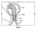
手術者がらせん縫合体1040を前進させると、先端1044は、胃の組織の壁部分704を貫通し、真空柱体1160の遠位端に向かう方向に組織中に進入することができる。らせん縫合体1040は、少なくとも部分的に胃壁の部分704を貫通してらせん状に巻くことができる。図32に示されているように、らせん縫合体1040のこの前進は、らせん縫合体1040が所定の位置に完全に位置し、胃壁の部分704に定着するまで継続することができる。 As the operator advances the
らせん縫合体1040を前進させることにより、胃の筋肉層のうちの1つ以上を貫通することができる。いくつかの実施例では、らせん縫合体1040が胃の外部層を貫通しない場合もある。図20A及び図20Bで説明したように、らせん縫合体1040の巻きは、所定の貫入深さで部分704の中に設定することができる。 Advancement of the
図32を参照すると、らせん縫合体1040が所定の長さだけ前進すると、束ねられた壁部分704内におけるらせん縫合体1040の固定が張力又は抵抗によって促進される。いくつかの実施例では、壁部分704への縫合の固定を維持し、らせん縫合体1040の移動又は組織からの後退を防止するために、らせん縫合体1040の1つ以上の末端にアンカ(図示せず)を配置することができる。 Referring to FIG. 32, as the
いくつかの実施例では、縫合体の先端1044は、らせん縫合体1040の鋭い先端が、筋肉及び胃壁の通常の運動中にその鋭い先端が壁部分の組織を擦ることによって裂離するのを防止するための裂離緩和特徴を有することができる。一実施例では、先端1044は、らせん縫合体の近位端を概ね鈍くすることができるよう、取外し可能にすることができる。他の実施例では、先端1044の少なくとも一部が壁部分704の表面から突出するように先端1044を配置することができる。 In some embodiments, the
図33を参照すると、らせん縫合体1040が壁部分704の中に固定されると、手術者は、らせん縫合体1040を展開させて、らせん縫合体1040の係合を縫合体ドライバ1100から解除することができる。近位端では、らせん縫合体1040を後退させて、縫合体コネクタ1060(図27ないし図31では切り欠かれている)とらせん縫合体1040の間の接着接続を破壊することにより、らせん縫合体1040の取付け部分1046を縫合体コネクタ1060(図17及び図25に示されている)から除去することができる。この破壊は、壁部分704の中に埋め込まれているらせん縫合体1040を維持する傾向を示す抵抗力によって容易にすることができる。 Referring to FIG. 33, once the
手術者は、真空柱体1160への吸引の印加が未だ停止されていない場合、その吸引の印加を停止することができる。手術者は、ハンドル組立体1006(図示せず)を使用して真空柱体1160を管腔706から引き出すことによって真空柱体1160を抜き取ることができる。胃壁の部分704を束ね、ほぼ一様な幅及び直径の胃スリーブを形成することにより、手術者は、胃の総容積をほぼ小さくすることができる。 When the application of suction to the
次に図34を参照すると、真空柱体1160が抜き取られると、手術者は、第2の胃縮小装置1000を引き出すことにより、患者の胃、食道及び口から第2の胃縮小装置1000を除去することができる。らせん縫合体1040は、壁部分704に定着し、且つ、埋め込まれた状態を維持し、通路706を形成することができる。いくつかの実施例では、通路706は、胃700の上部嚢708を下部嚢710に接続している。 Referring now to FIG. 34, once the
らせん縫合体1040は、容積が小さくなった胃空間の減量効果が望ましいものである限り、或いは通路の完全性が低下するまで、壁部分に定着した状態を無期限に維持することができる。いくつかの実施例では、らせん縫合体1040は、らせん縫合体1040へ復帰させ、且つ、最初にらせん縫合体1040を前進させるために必要とした方向とは逆の方向にらせん縫合体1040を回転させることにより、壁部分704から後退させ、或いは壁部分704との係合を解除することができる。 The
以上、本発明について、本発明の特定の好ましい実施例を参照して説明したが、開示したこれらの実施例は、その性質が本発明を限定するものではなく、説明を目的としたものであること、また、以上の開示には広範囲にわたる変形形態、修正、変更及び置換が企図されており、いくつかの例では、他の特徴の対応する使用を伴うことなく、本発明のいくつかの特徴を使用することができることに留意されたい。多くのこのような変形形態及び修正は、好ましい実施例についての以上の説明の精査に基づいて、当業者には望ましいものと思われる。したがって特許請求の範囲は、広義に、且つ、本発明の範囲と矛盾しない方法で解釈されるべきであることを理解されたい。 While the invention has been described with reference to certain preferred embodiments of the invention, the disclosed embodiments are not intended to limit the invention in nature but are intended to be illustrative. In addition, the above disclosure contemplates a wide range of variations, modifications, changes, and substitutions, and in some examples, some features of the present invention without the corresponding use of other features. Note that can be used. Many such variations and modifications will be desirable to those skilled in the art based on review of the above description of the preferred embodiment. It is therefore to be understood that the claims are to be interpreted in a broad sense and in a manner consistent with the scope of the present invention.
Claims (26)
Translated fromJapanese組織収集組立体にして、胃の内部部分を前記組織収集組立体に向かってへこますための力を前記内部部分に加えるように構成された組織収集組立体と、
前記組織収集組立体に移動可能に取り付けられた縫合体組立体にして、前記胃の中の第1の嚢と第2の嚢の間に胃スリーブを形成するために、前記胃の前記内部部分の中に前進するように構成された縫合体組立体と
を有している装置。A device for reducing the volume of the stomach,
A tissue collection assembly configured to apply a force to the internal collection portion to dent the internal portion of the stomach toward the tissue collection assembly;
The internal portion of the stomach for forming a stomach sleeve between the first and second sac in the stomach in a suture assembly movably attached to the tissue collection assembly. A suture assembly configured to be advanced into the device.
長手軸線に沿って延在している柱体にして、前記内部身体組織に真空力を加えるための真空源に結合するように構成された柱体と、
前記長手軸線に概ね沿った前記柱体の外側の表面に沿って延在している1つ以上のセクションと、
個々のセクション内に配置された1つ以上の真空開口にして、個々の開口が前記真空力を加えるための前記真空源を前記周囲の内部身体組織に接続する真空開口と
を有している装置。A device for forming a sleeve from surrounding internal body tissue,
A column extending along a longitudinal axis and configured to couple to a vacuum source for applying a vacuum force to the internal body tissue;
One or more sections extending along an outer surface of the column generally along the longitudinal axis;
An apparatus comprising one or more vacuum openings disposed in individual sections, each opening having a vacuum opening connecting the vacuum source for applying the vacuum force to the surrounding internal body tissue .
組織収集装置を提供する工程にして、前記組織収集装置が胃の内部部分を前記組織収集組立体に向かってへこますための力を前記内部部分に加えるように構成された工程と、
前記胃の中に前記組織収集装置を配置する工程にして、前記胃が食道を介してアクセスされる工程と、
前記胃の前記内部部分の組織を縫合領域内に集める工程にして、前記縫合領域が前記組織収集装置を直接取り囲む領域を含み、また、前記組織収集装置が、前記集められた組織から通路を形成する工程と、
前記縫合領域の近傍に縫合体を提供する工程と、
前記集められた組織の少なくとも一部に貫入するために、前記縫合体を前記縫合領域の中に前進させる工程と、
スリーブを形成するために前記集められた組織を束ねる工程とを有しており、
前記縫合体が前記スリーブの形状を維持するための構造を有している、方法。A method for reducing stomach volume,
Providing a tissue collection device, wherein the tissue collection device is configured to apply a force to the internal portion to dent the internal portion of the stomach toward the tissue collection assembly;
Placing the tissue collection device in the stomach, wherein the stomach is accessed via the esophagus;
Collecting the tissue of the internal portion of the stomach into a suture region, the suture region including a region directly surrounding the tissue collection device, and the tissue collection device forming a passageway from the collected tissue And a process of
Providing a suture in the vicinity of the suture region;
Advancing the suture into the suture region to penetrate at least a portion of the collected tissue;
Bundling the collected tissue to form a sleeve,
The method wherein the suture has a structure for maintaining the shape of the sleeve.
Applications Claiming Priority (3)
| Application Number | Priority Date | Filing Date | Title |
|---|---|---|---|
| US4317808P | 2008-04-08 | 2008-04-08 | |
| US61/043,178 | 2008-04-08 | ||
| PCT/US2009/039962WO2009126744A2 (en) | 2008-04-08 | 2009-04-08 | Apparatus and method for gastric reduction |
Publications (1)
| Publication Number | Publication Date |
|---|---|
| JP2011517977Atrue JP2011517977A (en) | 2011-06-23 |
Family
ID=40718629
Family Applications (1)
| Application Number | Title | Priority Date | Filing Date |
|---|---|---|---|
| JP2011504159APendingJP2011517977A (en) | 2008-04-08 | 2009-04-08 | Device and method for reducing stomach |
Country Status (7)
| Country | Link |
|---|---|
| US (1) | US20090275960A1 (en) |
| EP (1) | EP2285292A2 (en) |
| JP (1) | JP2011517977A (en) |
| AU (1) | AU2009233764A1 (en) |
| CA (1) | CA2721066A1 (en) |
| MX (1) | MX2010011036A (en) |
| WO (1) | WO2009126744A2 (en) |
Cited By (1)
| Publication number | Priority date | Publication date | Assignee | Title |
|---|---|---|---|---|
| JP2021053393A (en)* | 2019-09-30 | 2021-04-08 | ジャイラス・エーシーエムアイ・インコーポレーテッド | Suturing apparatus and method |
Families Citing this family (23)
| Publication number | Priority date | Publication date | Assignee | Title |
|---|---|---|---|---|
| CN102405022B (en) | 2009-03-14 | 2015-02-04 | 瓦索斯蒂奇股份有限公司 | Vessel access and closure device |
| JP5744893B2 (en)* | 2009-11-09 | 2015-07-08 | アントラージュ メディカル テクノロジーズ,インコーポレイテッドEntourage Medical Technologies,Inc. | Systems that provide access and closure to the organization |
| US10058314B2 (en) | 2010-01-20 | 2018-08-28 | Micro Interventional Devices, Inc. | Tissue closure device and method |
| US20110178537A1 (en) | 2010-01-20 | 2011-07-21 | Whitman Michael P | Tissue repair implant and delivery device and method |
| US10959840B2 (en) | 2010-01-20 | 2021-03-30 | Micro Interventional Devices, Inc. | Systems and methods for affixing a prosthesis to tissue |
| US9980708B2 (en) | 2010-01-20 | 2018-05-29 | Micro Interventional Devices, Inc. | Tissue closure device and method |
| US10743854B2 (en) | 2010-01-20 | 2020-08-18 | Micro Interventional Devices, Inc. | Tissue closure device and method |
| US8894667B2 (en) | 2010-03-09 | 2014-11-25 | University Of Louisville Research Foundation, Inc. | Endoscopic closure device |
| US9044267B2 (en) | 2010-06-11 | 2015-06-02 | Entourage Medical Technologies, Inc. | System and method for transapical access and closure |
| US9161778B2 (en) | 2010-06-11 | 2015-10-20 | Entourage Medical Technologies, Inc. | System and method for transapical access and closure |
| EP2584977A4 (en) | 2010-06-26 | 2017-08-09 | Vasostitch, Inc. | Method and apparatus for transapical access and closure |
| US9730690B2 (en) | 2010-09-20 | 2017-08-15 | Entourage Medical Technologies, Inc. | Method for providing surgical access |
| US9314362B2 (en)* | 2012-01-08 | 2016-04-19 | Vibrynt, Inc. | Methods, instruments and devices for extragastric reduction of stomach volume |
| US9808368B2 (en) | 2012-11-29 | 2017-11-07 | Boehringer Laboratories, Inc. | Methods for performing bariatric surgery using gastric sizing systems and instruments |
| US9452072B2 (en) | 2013-06-25 | 2016-09-27 | J. Mark Provenza | Apparatus and methods for anchoring in the stomach and the duodenum |
| EP3054860B1 (en) | 2013-10-10 | 2020-07-01 | Nitinotes Ltd. | Endoluminal sleeve gastroplasty |
| US10779979B2 (en) | 2013-10-10 | 2020-09-22 | Nitinotes Ltd. | Endoluminal sleeve gastroplasty |
| AU2014342300A1 (en) | 2013-10-29 | 2016-05-19 | Entourage Medical Technologies, Inc. | System for providing surgical access |
| US10159425B2 (en)* | 2013-11-08 | 2018-12-25 | Covidien Lp | Devices and methods facilitating sleeve gastrectomy and other procedures |
| EP3203918B1 (en)* | 2014-10-08 | 2023-09-20 | Nitinotes Ltd. | Endoluminal sleeve gastroplasty |
| EP3232941B1 (en) | 2014-12-19 | 2023-11-08 | Meacor, Inc. | Surgical system |
| JP7322051B2 (en) | 2018-03-15 | 2023-08-07 | リンテック・オヴ・アメリカ,インコーポレイテッド | Fabrication of nerve scaffolds on carbon nanofiber yarns |
| US20230309989A1 (en)* | 2022-03-31 | 2023-10-05 | Ethicon, Inc. | Assembly and Method for Closing a Tissue Opening |
Family Cites Families (58)
| Publication number | Priority date | Publication date | Assignee | Title |
|---|---|---|---|---|
| US4524771A (en)* | 1982-10-28 | 1985-06-25 | Ethicon Inc. | Multiple curved surgical needle |
| US5348535A (en)* | 1990-12-14 | 1994-09-20 | Rocin Laboratories, Inc. | Power-assisted liposuction instrument and cannula assembly therefor |
| US6394973B1 (en)* | 1990-12-14 | 2002-05-28 | Robert L. Cucin | Power-assisted liposuction instrument with cauterizing cannula assembly |
| DE4304353A1 (en)* | 1992-10-24 | 1994-04-28 | Helmut Dipl Ing Wurster | Suturing device used in endoscopic surgical operations - has helical needle with fixed non-traumatic thread held and rotated by rollers attached to instrument head extended into patients body. |
| US5356424A (en)* | 1993-02-05 | 1994-10-18 | American Cyanamid Co. | Laparoscopic suturing device |
| US5810851A (en)* | 1996-03-05 | 1998-09-22 | Yoon; Inbae | Suture spring device |
| US6464697B1 (en)* | 1998-02-19 | 2002-10-15 | Curon Medical, Inc. | Stomach and adjoining tissue regions in the esophagus |
| US6071260A (en)* | 1997-09-18 | 2000-06-06 | The California Institute Of Tissue Engineering And Instrumentation, Llc | Ultrasonic liposuction device and a method of using the same |
| US6254642B1 (en)* | 1997-12-09 | 2001-07-03 | Thomas V. Taylor | Perorally insertable gastroesophageal anti-reflux valve prosthesis and tool for implantation thereof |
| US5947983A (en)* | 1998-03-16 | 1999-09-07 | Boston Scientific Corporation | Tissue cutting and stitching device and method |
| US6214030B1 (en)* | 1998-08-10 | 2001-04-10 | Mani, Inc. | Suture needle |
| US6663639B1 (en)* | 1999-06-22 | 2003-12-16 | Ndo Surgical, Inc. | Methods and devices for tissue reconfiguration |
| US6626917B1 (en)* | 1999-10-26 | 2003-09-30 | H. Randall Craig | Helical suture instrument |
| EP1261282B1 (en)* | 2000-03-03 | 2013-09-25 | C. R. Bard, Inc. | Endoscopic tissue apposition device with multiple suction ports |
| US6572629B2 (en)* | 2000-08-17 | 2003-06-03 | Johns Hopkins University | Gastric reduction endoscopy |
| US6514263B1 (en)* | 2000-08-30 | 2003-02-04 | Ethicon Endo-Surgery, Inc. | Helical needle and suture combination having a strain relief element |
| US7033373B2 (en)* | 2000-11-03 | 2006-04-25 | Satiety, Inc. | Method and device for use in minimally invasive placement of space-occupying intragastric devices |
| US6535764B2 (en)* | 2001-05-01 | 2003-03-18 | Intrapace, Inc. | Gastric treatment and diagnosis device and method |
| US6676677B2 (en)* | 2001-05-11 | 2004-01-13 | Jeffrey A. Klein | Liposuction cannula with abrading apertures |
| US7083629B2 (en)* | 2001-05-30 | 2006-08-01 | Satiety, Inc. | Overtube apparatus for insertion into a body |
| US6558400B2 (en)* | 2001-05-30 | 2003-05-06 | Satiety, Inc. | Obesity treatment tools and methods |
| US20040082859A1 (en)* | 2002-07-01 | 2004-04-29 | Alan Schaer | Method and apparatus employing ultrasound energy to treat body sphincters |
| US6773440B2 (en)* | 2002-07-02 | 2004-08-10 | Satiety, Inc. | Method and device for use in tissue approximation and fixation |
| US6746460B2 (en)* | 2002-08-07 | 2004-06-08 | Satiety, Inc. | Intra-gastric fastening devices |
| US7033384B2 (en)* | 2002-08-30 | 2006-04-25 | Satiety, Inc. | Stented anchoring of gastric space-occupying devices |
| US7214233B2 (en)* | 2002-08-30 | 2007-05-08 | Satiety, Inc. | Methods and devices for maintaining a space occupying device in a relatively fixed location within a stomach |
| US6981978B2 (en)* | 2002-08-30 | 2006-01-03 | Satiety, Inc. | Methods and devices for maintaining a space occupying device in a relatively fixed location within a stomach |
| AU2003270549A1 (en)* | 2002-09-09 | 2004-03-29 | Brian Kelleher | Device and method for endoluminal therapy |
| US7229428B2 (en)* | 2002-10-23 | 2007-06-12 | Satiety, Inc. | Method and device for use in endoscopic organ procedures |
| US7220237B2 (en)* | 2002-10-23 | 2007-05-22 | Satiety, Inc. | Method and device for use in endoscopic organ procedures |
| US6656194B1 (en)* | 2002-11-05 | 2003-12-02 | Satiety, Inc. | Magnetic anchoring devices |
| US7175638B2 (en)* | 2003-04-16 | 2007-02-13 | Satiety, Inc. | Method and devices for modifying the function of a body organ |
| US7914543B2 (en)* | 2003-10-14 | 2011-03-29 | Satiety, Inc. | Single fold device for tissue fixation |
| US7097650B2 (en)* | 2003-10-14 | 2006-08-29 | Satiety, Inc. | System for tissue approximation and fixation |
| US20050177176A1 (en)* | 2004-02-05 | 2005-08-11 | Craig Gerbi | Single-fold system for tissue approximation and fixation |
| CA2556228C (en)* | 2004-02-13 | 2014-05-13 | Satiety, Inc. | Methods for reducing hollow organ volume |
| MXPA06009971A (en)* | 2004-02-27 | 2007-08-08 | Satiety Inc | Methods and devices for reducing hollow organ volume. |
| US8628547B2 (en)* | 2004-03-09 | 2014-01-14 | Ethicon Endo-Surgery, Inc. | Devices and methods for placement of partitions within a hollow body organ |
| US9028511B2 (en)* | 2004-03-09 | 2015-05-12 | Ethicon Endo-Surgery, Inc. | Devices and methods for placement of partitions within a hollow body organ |
| US8252009B2 (en)* | 2004-03-09 | 2012-08-28 | Ethicon Endo-Surgery, Inc. | Devices and methods for placement of partitions within a hollow body organ |
| US8449560B2 (en)* | 2004-03-09 | 2013-05-28 | Satiety, Inc. | Devices and methods for placement of partitions within a hollow body organ |
| AU2005231323B2 (en)* | 2004-03-26 | 2011-03-31 | Ethicon Endo-Surgery, Inc | Systems and methods for treating obesity |
| US20050277975A1 (en)* | 2004-06-09 | 2005-12-15 | Usgi Medical Corp. | Methods and apparatus for creating a working space within a body lumen or cavity |
| US8172857B2 (en)* | 2004-08-27 | 2012-05-08 | Davol, Inc. | Endoscopic tissue apposition device and method of use |
| US20060106288A1 (en)* | 2004-11-17 | 2006-05-18 | Roth Alex T | Remote tissue retraction device |
| US7674271B2 (en)* | 2005-05-04 | 2010-03-09 | InTailor Surgical, Inc. | Endoluminal gastric ring and method |
| US20060253126A1 (en)* | 2005-05-04 | 2006-11-09 | Bernard Medical, Llc | Endoluminal suturing device and method |
| US20060253127A1 (en) | 2005-05-04 | 2006-11-09 | Bernard Medical, Llc | Endoluminal linear suturing device |
| US7615060B2 (en)* | 2005-06-13 | 2009-11-10 | Ethicon-Endo Surgery, Inc. | Endoscopic suturing device |
| US8641729B2 (en)* | 2005-07-13 | 2014-02-04 | Creighton University | Systems and techniques for minimally invasive gastrointestinal procedures |
| US8252006B2 (en)* | 2005-08-05 | 2012-08-28 | Ethicon Endo-Surgery, Inc. | Single pass gastric restriction with a corkscrew style wall anchor |
| US7896890B2 (en)* | 2005-09-02 | 2011-03-01 | Ethicon Endo-Surgery, Inc. | Method and apparatus for endoscopically performing gastric reduction surgery in a single step |
| US9055942B2 (en)* | 2005-10-03 | 2015-06-16 | Boston Scienctific Scimed, Inc. | Endoscopic plication devices and methods |
| US8221438B2 (en) | 2006-02-17 | 2012-07-17 | Ethicon Endo-Surgery, Inc. | Lumen reduction methods and devices |
| WO2007098212A2 (en) | 2006-02-18 | 2007-08-30 | Amir Belson | Endoscopic suturing devices |
| US8187297B2 (en)* | 2006-04-19 | 2012-05-29 | Vibsynt, Inc. | Devices and methods for treatment of obesity |
| US20070276409A1 (en)* | 2006-05-25 | 2007-11-29 | Ethicon Endo-Surgery, Inc. | Endoscopic gastric restriction methods and devices |
| WO2008112942A2 (en)* | 2007-03-13 | 2008-09-18 | Harris Peter S | Methods and devices for reducing gastric volume |
- 2009
- 2009-04-08JPJP2011504159Apatent/JP2011517977A/enactivePending
- 2009-04-08MXMX2010011036Apatent/MX2010011036A/ennot_activeApplication Discontinuation
- 2009-04-08CACA2721066Apatent/CA2721066A1/ennot_activeAbandoned
- 2009-04-08AUAU2009233764Apatent/AU2009233764A1/ennot_activeAbandoned
- 2009-04-08WOPCT/US2009/039962patent/WO2009126744A2/enactiveApplication Filing
- 2009-04-08USUS12/420,759patent/US20090275960A1/ennot_activeAbandoned
- 2009-04-08EPEP09729395Apatent/EP2285292A2/ennot_activeWithdrawn
Cited By (4)
| Publication number | Priority date | Publication date | Assignee | Title |
|---|---|---|---|---|
| JP2021053393A (en)* | 2019-09-30 | 2021-04-08 | ジャイラス・エーシーエムアイ・インコーポレーテッド | Suturing apparatus and method |
| JP7354077B2 (en) | 2019-09-30 | 2023-10-02 | ジャイラス エーシーエムアイ インク ディー/ビー/エー オリンパス サージカル テクノロジーズ アメリカ | Suturing device and method |
| US11826040B2 (en) | 2019-09-30 | 2023-11-28 | Gyrus Acmi, Inc. | Suturing apparatus and method |
| US12042141B2 (en) | 2019-09-30 | 2024-07-23 | Gyrus Acmi, Inc. | Suturing apparatus and method |
Also Published As
| Publication number | Publication date |
|---|---|
| US20090275960A1 (en) | 2009-11-05 |
| WO2009126744A2 (en) | 2009-10-15 |
| MX2010011036A (en) | 2011-02-24 |
| EP2285292A2 (en) | 2011-02-23 |
| WO2009126744A3 (en) | 2009-12-03 |
| AU2009233764A1 (en) | 2009-10-15 |
| CA2721066A1 (en) | 2009-10-15 |
Similar Documents
| Publication | Publication Date | Title |
|---|---|---|
| JP2011517977A (en) | Device and method for reducing stomach | |
| AU2010241552B2 (en) | Medical systems, devices and methods for suturing perforations | |
| US8939902B2 (en) | Remote tissue retraction device | |
| CN118750058A (en) | Endoscopic tissue zooming system and method | |
| US20060253127A1 (en) | Endoluminal linear suturing device | |
| JP2013514866A (en) | Medical instrument and method for suturing tissue | |
| JP2013154187A (en) | System and technique for minimally invasive gastrointestinal procedure | |
| CA2963075C (en) | Endoluminal sleeve gastroplasty | |
| US9833350B2 (en) | Anchorable size-varying gastric balloons for weight loss | |
| US20170304099A1 (en) | Endoluminal sleeve gastroplasty | |
| US20110245846A1 (en) | Endoscopic tissue anchor deployment devices and methods | |
| EP3223898B1 (en) | Anchorable size-varying gastric balloons for weight loss |